EP3362259B1 - Dispositif et procédé de fabrication d'un objet en trois dimensions - Google Patents
Dispositif et procédé de fabrication d'un objet en trois dimensions Download PDFInfo
- Publication number
- EP3362259B1 EP3362259B1 EP16778275.4A EP16778275A EP3362259B1 EP 3362259 B1 EP3362259 B1 EP 3362259B1 EP 16778275 A EP16778275 A EP 16778275A EP 3362259 B1 EP3362259 B1 EP 3362259B1
- Authority
- EP
- European Patent Office
- Prior art keywords
- unit
- irradiation
- units
- recoating
- building material
- Prior art date
- Legal status (The legal status is an assumption and is not a legal conclusion. Google has not performed a legal analysis and makes no representation as to the accuracy of the status listed.)
- Active
Links
Images


Classifications
-
- B—PERFORMING OPERATIONS; TRANSPORTING
- B29—WORKING OF PLASTICS; WORKING OF SUBSTANCES IN A PLASTIC STATE IN GENERAL
- B29C—SHAPING OR JOINING OF PLASTICS; SHAPING OF MATERIAL IN A PLASTIC STATE, NOT OTHERWISE PROVIDED FOR; AFTER-TREATMENT OF THE SHAPED PRODUCTS, e.g. REPAIRING
- B29C64/00—Additive manufacturing, i.e. manufacturing of three-dimensional [3D] objects by additive deposition, additive agglomeration or additive layering, e.g. by 3D printing, stereolithography or selective laser sintering
- B29C64/10—Processes of additive manufacturing
- B29C64/141—Processes of additive manufacturing using only solid materials
- B29C64/153—Processes of additive manufacturing using only solid materials using layers of powder being selectively joined, e.g. by selective laser sintering or melting
-
- B—PERFORMING OPERATIONS; TRANSPORTING
- B22—CASTING; POWDER METALLURGY
- B22F—WORKING METALLIC POWDER; MANUFACTURE OF ARTICLES FROM METALLIC POWDER; MAKING METALLIC POWDER; APPARATUS OR DEVICES SPECIALLY ADAPTED FOR METALLIC POWDER
- B22F10/00—Additive manufacturing of workpieces or articles from metallic powder
- B22F10/20—Direct sintering or melting
- B22F10/28—Powder bed fusion, e.g. selective laser melting [SLM] or electron beam melting [EBM]
-
- B—PERFORMING OPERATIONS; TRANSPORTING
- B22—CASTING; POWDER METALLURGY
- B22F—WORKING METALLIC POWDER; MANUFACTURE OF ARTICLES FROM METALLIC POWDER; MAKING METALLIC POWDER; APPARATUS OR DEVICES SPECIALLY ADAPTED FOR METALLIC POWDER
- B22F12/00—Apparatus or devices specially adapted for additive manufacturing; Auxiliary means for additive manufacturing; Combinations of additive manufacturing apparatus or devices with other processing apparatus or devices
- B22F12/40—Radiation means
- B22F12/44—Radiation means characterised by the configuration of the radiation means
- B22F12/45—Two or more
-
- B—PERFORMING OPERATIONS; TRANSPORTING
- B22—CASTING; POWDER METALLURGY
- B22F—WORKING METALLIC POWDER; MANUFACTURE OF ARTICLES FROM METALLIC POWDER; MAKING METALLIC POWDER; APPARATUS OR DEVICES SPECIALLY ADAPTED FOR METALLIC POWDER
- B22F12/00—Apparatus or devices specially adapted for additive manufacturing; Auxiliary means for additive manufacturing; Combinations of additive manufacturing apparatus or devices with other processing apparatus or devices
- B22F12/60—Planarisation devices; Compression devices
- B22F12/67—Blades
-
- B—PERFORMING OPERATIONS; TRANSPORTING
- B29—WORKING OF PLASTICS; WORKING OF SUBSTANCES IN A PLASTIC STATE IN GENERAL
- B29C—SHAPING OR JOINING OF PLASTICS; SHAPING OF MATERIAL IN A PLASTIC STATE, NOT OTHERWISE PROVIDED FOR; AFTER-TREATMENT OF THE SHAPED PRODUCTS, e.g. REPAIRING
- B29C64/00—Additive manufacturing, i.e. manufacturing of three-dimensional [3D] objects by additive deposition, additive agglomeration or additive layering, e.g. by 3D printing, stereolithography or selective laser sintering
- B29C64/10—Processes of additive manufacturing
- B29C64/165—Processes of additive manufacturing using a combination of solid and fluid materials, e.g. a powder selectively bound by a liquid binder, catalyst, inhibitor or energy absorber
-
- B—PERFORMING OPERATIONS; TRANSPORTING
- B29—WORKING OF PLASTICS; WORKING OF SUBSTANCES IN A PLASTIC STATE IN GENERAL
- B29C—SHAPING OR JOINING OF PLASTICS; SHAPING OF MATERIAL IN A PLASTIC STATE, NOT OTHERWISE PROVIDED FOR; AFTER-TREATMENT OF THE SHAPED PRODUCTS, e.g. REPAIRING
- B29C64/00—Additive manufacturing, i.e. manufacturing of three-dimensional [3D] objects by additive deposition, additive agglomeration or additive layering, e.g. by 3D printing, stereolithography or selective laser sintering
- B29C64/20—Apparatus for additive manufacturing; Details thereof or accessories therefor
- B29C64/205—Means for applying layers
-
- B—PERFORMING OPERATIONS; TRANSPORTING
- B33—ADDITIVE MANUFACTURING TECHNOLOGY
- B33Y—ADDITIVE MANUFACTURING, i.e. MANUFACTURING OF THREE-DIMENSIONAL [3D] OBJECTS BY ADDITIVE DEPOSITION, ADDITIVE AGGLOMERATION OR ADDITIVE LAYERING, e.g. BY 3D PRINTING, STEREOLITHOGRAPHY OR SELECTIVE LASER SINTERING
- B33Y10/00—Processes of additive manufacturing
-
- B—PERFORMING OPERATIONS; TRANSPORTING
- B33—ADDITIVE MANUFACTURING TECHNOLOGY
- B33Y—ADDITIVE MANUFACTURING, i.e. MANUFACTURING OF THREE-DIMENSIONAL [3D] OBJECTS BY ADDITIVE DEPOSITION, ADDITIVE AGGLOMERATION OR ADDITIVE LAYERING, e.g. BY 3D PRINTING, STEREOLITHOGRAPHY OR SELECTIVE LASER SINTERING
- B33Y30/00—Apparatus for additive manufacturing; Details thereof or accessories therefor
-
- B—PERFORMING OPERATIONS; TRANSPORTING
- B33—ADDITIVE MANUFACTURING TECHNOLOGY
- B33Y—ADDITIVE MANUFACTURING, i.e. MANUFACTURING OF THREE-DIMENSIONAL [3D] OBJECTS BY ADDITIVE DEPOSITION, ADDITIVE AGGLOMERATION OR ADDITIVE LAYERING, e.g. BY 3D PRINTING, STEREOLITHOGRAPHY OR SELECTIVE LASER SINTERING
- B33Y40/00—Auxiliary operations or equipment, e.g. for material handling
- B33Y40/10—Pre-treatment
-
- B—PERFORMING OPERATIONS; TRANSPORTING
- B22—CASTING; POWDER METALLURGY
- B22F—WORKING METALLIC POWDER; MANUFACTURE OF ARTICLES FROM METALLIC POWDER; MAKING METALLIC POWDER; APPARATUS OR DEVICES SPECIALLY ADAPTED FOR METALLIC POWDER
- B22F12/00—Apparatus or devices specially adapted for additive manufacturing; Auxiliary means for additive manufacturing; Combinations of additive manufacturing apparatus or devices with other processing apparatus or devices
- B22F12/10—Auxiliary heating means
- B22F12/13—Auxiliary heating means to preheat the material
-
- Y—GENERAL TAGGING OF NEW TECHNOLOGICAL DEVELOPMENTS; GENERAL TAGGING OF CROSS-SECTIONAL TECHNOLOGIES SPANNING OVER SEVERAL SECTIONS OF THE IPC; TECHNICAL SUBJECTS COVERED BY FORMER USPC CROSS-REFERENCE ART COLLECTIONS [XRACs] AND DIGESTS
- Y02—TECHNOLOGIES OR APPLICATIONS FOR MITIGATION OR ADAPTATION AGAINST CLIMATE CHANGE
- Y02P—CLIMATE CHANGE MITIGATION TECHNOLOGIES IN THE PRODUCTION OR PROCESSING OF GOODS
- Y02P10/00—Technologies related to metal processing
- Y02P10/25—Process efficiency
Definitions
- the present invention relates to a device and a method for producing a three-dimensional object by applying and selectively solidifying a building material in layers.
- Devices and methods of this type are used, for example, in rapid prototyping, rapid tooling or additive manufacturing.
- An example of such a process is known as "selective laser sintering or laser melting".
- a thin layer of a powdery building material is repeatedly applied and the building material is selectively solidified in each layer by selective irradiation with a laser beam.
- WO 2015/091485 A1 describes a device for selective laser melting in which one of a VCSEL series (Vertical Cavity Surface Emitting Laser) or a VECSEL series (Vertical External Cavity Surface Emitting Laser) line exposure unit moves over an applied powder layer and selectively solidifies it.
- VCSEL series Vertical Cavity Surface Emitting Laser
- VECSEL series Very External Cavity Surface Emitting Laser
- DE 10 2015 213 140 describes a device for producing a three-dimensional object, in which a coater and an exposure unit are moved together or separately from one another over a construction field intended for building the object.
- the WO 2015/106838 A1 describes an apparatus for producing a three-dimensional object by solidifying a binder.
- the device comprises a carrier which can move bidirectionally along a first axis relative to a carrier platform, the carrier being designed to receive different modules in order to each carry out one step of a series of steps for the production of a layer of a three-dimensional object.
- the apparatus further comprises a controller for causing relative movement between the carrier and the carrier platform along the first axis and, during the relative movement, controlling the operation of the modules to carry out the series of steps in a predefined order
- the DE 10 2012 212 587 A1 describes a device for producing a three-dimensional object, in which a coater and two heating elements are moved over a construction field intended for building up the object, the first and second heating elements being arranged on both sides of the coater.
- the object of the present invention is to provide an alternative or improved device or an alternative or improved method for producing a three-dimensional object by applying and selectively solidifying a powdery building material in layers.
- the device according to the invention serves to produce a three-dimensional object by applying and selectively solidifying a building material in layers. It contains a coater that can be moved in a coating direction over a construction field with at least one first coating unit for applying a layer of the building material to the construction field and an exposure unit that can be moved in the coating direction over the construction field with at least one first exposure unit, which is suitable for sending out one for solidifying the building material Radiation is suitable for the selective solidification of the applied layer of the building material at locations that correspond to a cross section of the object to be manufactured.
- the device is designed and / or controlled to repeat the steps of application and selective solidification until the object is completed.
- the coater contains at least one second coating unit which is arranged in the coating direction on the other side of the first exposure unit than the first coating unit. Additionally or alternatively, the exposure unit contains at least one second exposure unit, which is arranged in the coating direction on the other side of the first coating unit than the first exposure unit.
- the first exposure unit and any further exposure units are designed as line exposure units, in particular as VCSEL-based or VECSEL-based line exposure units.
- the building material can be solidified particularly efficiently by means of radiation.
- the device preferably contains two or more coating units and two or more exposure units, the coating units and the exposure units being arranged alternately in the coating direction, with preferably the two units lying first and last in the coating direction either both being a coating unit or both being an exposure unit.
- the production time for the object can be further shortened and thus productivity can be further increased.
- the device preferably contains two or more coating units and two or more exposure units, with at least one coating unit being arranged between two exposure units, the two foremost and last units in the coating direction each being a coating unit. In this way, for example, the production time for the object can be shortened even with a double coating and thus productivity can be increased.
- the number of coating units is greater, particularly preferably one greater than the number of exposure units.
- the number of coating units thus exceeds that of the exposure units, which in particular has financial savings effects: Exposure units are currently usually more expensive to purchase because their functions are more complicated than coating units.
- the overall operation can be simplified by this measure: Each exposure unit must generally be operated actively, i.e. in particular it must be able to be controlled. This means that signal connections are assigned to each exposure unit.
- an active control of coating units is not absolutely necessary in their operation, so that a simplification can also be achieved in terms of process technology by a higher number of coating units than exposure units.
- the coater and / or the exposer is preferably designed for this purpose, both during a movement in the coating direction as well as to apply a layer of the building material to the building field or to solidify the applied layer of building material when moving in a direction opposite to the coating direction.
- the device can be operated in two directions, namely the coating direction and its opposite direction.
- the first coating unit and / or any further coating units and the first exposure unit and / or any further exposure units are preferably mounted in the device in a height-adjustable manner, in particular their height can be controlled. In this way, for example, all the units just mentioned can each be set or controlled to a height suitable for the current operation of the device.
- the device preferably further contains a height-adjustable support which is intended to hold the powder layers applied.
- a height-adjustable support which is intended to hold the powder layers applied.
- the layer thickness of the applied powder layer can be adjusted by lowering the carrier.
- the device preferably further contains a radiant heater for heating the applied powder layer before it solidifies.
- a radiant heater for heating the applied powder layer before it solidifies.
- the applied powder layer can be preheated before it solidifies.
- the method according to the invention is used to produce a three-dimensional object by applying and selectively solidifying a building material in layers. It includes the following Steps: applying a layer of the building material by means of a coater moving in one coating direction over a construction field with at least one first coating unit, selective solidification of the applied layer of the building material at locations that correspond to a cross section of the object to be produced by means of an exposure device moving over the construction field with at least a first exposure unit and repeating the steps of applying and selectively solidifying until the object is completed.
- the coater contains at least one second coating unit, which is arranged in the coating direction on the other side of the first exposure unit than the first coating unit.
- the exposure unit contains at least one second exposure unit, which is arranged in the coating direction on the other side of the first coating unit than the first exposure unit.
- first exposure unit and any further exposure units are designed as line exposure units, in particular as VCSEL-based or VECSEL-based line exposure units.
- each coating unit and each exposure unit are moved once in a first direction over the construction field and then each coating unit and each exposure unit in the reverse order once in one of the first direction moves across the construction field in the opposite direction.
- the device can be operated in two directions (that is, in the coating direction and its opposite direction).
- Each coating unit and / or each exposure unit is preferably set higher by a predefined height, preferably by the height corresponding to a layer thickness of the building material, than the preceding coating unit in the respective direction of movement.
- at least some (preferably all) of the (in particular) coating units or exposure units, as mentioned above, are mounted in the device in a height-adjustable manner. In this way, for example, several layers can be applied and solidified during one pass, i.e. in the course of a movement of all coating units and solidification units in one direction of movement or in the direction of movement and the direction of movement opposite to it.
- At least one coating unit and at least one exposure unit are preferably moved over the construction field in such a way that a coating process and a solidification process take place at the same time at different locations on the construction field.
- the production time for the object can be further shortened and thus productivity can be further increased.
- each exposure unit is an exposure unit that emits radiation that is suitable for solidifying the building material
- a focal plane of the emitted radiation is set higher than that of the each exposure unit by a predefined height, preferably by the height corresponding to a layer thickness of the building material preceding exposure unit in the respective direction of movement.
- the build-up material can be solidified by means of radiation, and the setting of the focal plane can make a height-adjustable attachment of the exposure units superfluous or supplement it.
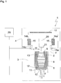
- a device 1 according to a first embodiment of the present invention is described.
- the device shown is a laser sintering or laser melting device 1.
- it contains a process chamber 3 with a chamber wall 4.
- a working plane 7 is defined by the upper opening of the container 5, the area of the working plane 7 lying within the opening, which can be used to build up the object 2, is referred to as construction field 8.
- a carrier 10 which is movable in a vertical direction V and to which a base plate 11 is attached which closes the container 5 at the bottom and thus forms its bottom.
- the base plate 11 can be a plate formed separately from the carrier 10 and attached to the carrier 10, or it can be formed integrally with the carrier 10.
- a construction platform 12 on which the object 2 is built can also be attached to the base plate 11.
- the object 2 can, however, also be built on the base plate 11 itself, which then serves as a construction platform.
- Fig. 1 the object 2 to be formed in the container 5 on the construction platform 12 below the working plane 7 is shown in an intermediate state with several solidified layers, surrounded by building material 13 that has remained unsolidified.
- the laser sintering device 1 further contains two storage containers 14a, 14b for a powdery building material 15 which can be solidified by electromagnetic radiation and a coater 16, which contains two coating units 16a, 16b movable in a horizontal direction H over the building field, for applying the building material 15 to the building field 8
- the radiant heater 17 is formed, for example, as an infrared heater.
- the laser sintering device 1 also contains an exposer 20 which can also be moved in the horizontal direction H over the construction field and which generates laser radiation 21 which is focused on the working plane 7.
- the imagesetter 20 includes a single exposure unit.
- This exposure unit 20 is designed as a line exposure unit which is capable of selectively exposing a line which extends transversely to its direction of movement and which extends over the entire area to be exposed.
- the laser sintering device 1 also contains a control unit 29, via which the individual components of the device 1 are controlled in a coordinated manner in order to carry out the construction process.
- the control unit can contain a CPU, the operation of which is controlled by a computer program (software).
- the computer program can be stored separately from the device on a storage medium from which it can be loaded into the device, in particular into the control unit 29.
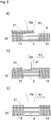
- Fig. 2a to f show steps of a method for producing a three-dimensional object by means of the device 1.
- the solidified part of the object 2 to be produced is surrounded by powder 13 that has remained unsolidified.
- the coating units 16a and 16b and the exposure unit 20 are arranged to the left of the construction field 8.
- the carrier 10 is first lowered by a height that corresponds to the desired layer thickness. Then as in Fig. 2a shown on the previously applied and selectively solidified powder layer 30 by means of a movement of the first coating unit 16a in a first coating direction R1 powdery build-up material 15 applied in the form of a first further powder layer 31.
- the application takes place at least over the entire cross section of the object 2 to be produced, preferably over the entire construction field 8, that is to say the area of the working plane 7, which can be lowered by a vertical movement of the carrier.
- the powder applied is preheated by the radiant heater 17.
- the imagesetter 20 then moves as in FIG Figure 2b shown in a first exposure direction, which is preferably the same as the first coating direction R1, over the construction field and selectively exposes the first further powder layer 31.
- the amount of energy introduced by the laser radiation 21 is set so that the cross-section of the object 2 to be produced A complete solidification of the powdery build-up material 15 takes place at corresponding points.
- the second coating unit 16b then performs as in FIG Figure 2b 1 shows an empty run in the first coating direction R1, ie it moves over the construction field 8 without applying construction material 15.
- the carrier 10 is lowered by a height that corresponds to the desired layer thickness.
- Fig. 2d shown on the previously applied and selectively solidified powder layer 31 by means of a movement of the second coating unit 16b in a second coating direction R2, which is the first coating direction R1 is opposite, powdery build-up material 15 is applied in the form of a second further powder layer 32.
- Opposite does not necessarily mean an angle of 180 ° in a plan view of the working plane, but only that the second coating direction R2 has a component which points in the opposite direction to the first coating direction R1.
- the angle between the first and the second coating direction is preferably between 15 and 210 degrees, more preferably it is 180 °.
- the application of the second further powder layer 32 takes place at least over the entire cross section of the object 2 to be manufactured, preferably over the entire construction field 8. During and after the application of the second further powder layer 32, the applied powder is preheated by the radiant heater 17.
- the imagesetter 20 then moves as in FIG Fig. 2e shown in a second exposure direction, which is preferably the same as the second coating direction R2, over the construction field and selectively exposes the second further powder layer 32.
- the amount of energy introduced by the laser radiation 21 is set so that the cross-section of the object 2 to be produced A complete solidification of the powdery build-up material 15 takes place at corresponding points.
- the first coating unit then performs as in Fig. 2f is shown an empty run in the first coating direction R1 over the construction field 8.
- the coating units 16a, 16b each require different height settings for the application of a powder layer or an empty run, they are height-adjustable, in particular their height is controllable, and mounted in the device 1.
- the device 1 of the present embodiment is characterized in that a coating unit 16a, 16b is arranged on each side of the imagesetter 20. This enables operation of the device as described above with reference to FIG Fig. 2a to f is described. With this operation, the production time for the object can be shortened considerably compared with the case in which only one coating unit is arranged on one side of the imagesetter, and thus the productivity of the apparatus can be increased.
- the coating travel and empty travel functions can also be interchanged.
- the coating unit 16a initially performs according to Fig. 2f (of the previous cycle) an empty run in the direction R2, then reverses and leads according to Fig. 2a (of the following cycle) a coating run in the direction of R1.
- the coating unit 16b also initially performs according to FIG Figure 2c an empty run in the direction R1 through, then reverses and leads according to Fig. 2d a coating run in the direction R2.
- one of the coating units or both can carry out a coating run before it is reversed and an empty run after it has reversed.
- the heating time that can be used for the heating process can be extended.
- one or both of the coating units can also carry out a coating run both before and after their reversal, during which a powder distribution layer is applied with a reduced thickness, the sum of the thicknesses of the two powder distribution layers yielding the desired total thickness of the powder layer.
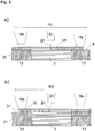
- Figures 3a and b show steps of an alternative method for producing a three-dimensional object by means of the device 1.
- This alternative method differs from that in FIG Fig. 2a to f
- the method shown is that the imagesetter 20 and the coating units 16a, 16b are moved together over the construction field instead of separately from one another. All other features of the method described above can also be transferred to the alternative method.
- Fig. 3a shows a method step in which the in Fig. 2a to c are combined with one another.
- the first coating unit 16a moves in the first coating direction R1 over the construction field 8 and applies the first further powder layer 31, which is then preheated by the radiant heater 17. While the first coating unit 16a is still moving over the construction field, at a distance behind it, the exposure device 21 also moves in the first coating direction R1 over the already completely applied area of the first further powder layer 31 and selectively solidifies it. At a distance behind the imagesetter, the second coating unit 16b runs an empty run in the first coating direction R1.
- Figure 3b shows a repetition of the in Fig. 3a shown in the reverse direction and represents a combination of the in Fig. 2d to f
- the second coating unit 16b applies the second further powder layer 32 in the second coating direction R2, which is then preheated by the radiant heater 17.
- the exposer 21 also travels in the second coating direction R2 over the already completely applied area of the second further powder layer 32 and selectively solidifies it.
- the first coating unit 16a runs an empty run in the second coating direction R2.
- this alternative method does not wait until a unit has driven over the construction field before the next unit begins its journey, a coating process and a consolidation process take place at the same time at different locations on the construction field. As a result, the production time for the object can be further shortened and productivity can be further increased.
- one of the coating units or both carry out a coating run before their reversal and an empty run after their reversal or carry out a coating run for a partial powder layer of reduced thickness both before and after their reversal.
- Figures 4a to d show various modifications of the in Fig. 1 device shown. These modifications differ from one another in the number and arrangement of the coating units and exposure units.
- Figure 4a shows schematically the in Fig. 1 Arrangement shown in a plan view.
- the exposure unit 20 contains a single exposure unit, while the application unit 16 contains two coating units 16a, 16b which are arranged in the coating direction R on both sides of the exposure unit, that is to say in front of and behind the exposure unit.
- the arrangement of the coating units is, so to speak, "mirrored" on the imagesetter.
- Figure 4b shows a reverse arrangement.
- the exposure unit is doubled here and on the Coater mirrored.
- the coater 16 thus contains a single coating unit in this case, while the exposure unit 20 contains two exposure units 20a, 20b, which are arranged in the coating direction R on both sides of the coater, that is, in front of and behind the coater.
- FIG. 1 The operation of a device with this arrangement is analogous to that in FIG Fig. 2 and 3 operation shown in Fig. 1 device shown.
- the preceding exposure unit performs an empty run
- the coating unit applies the new powder layer
- the respective subsequent exposure unit consolidates the newly applied powder layer.
- one of the exposure units or both can perform an exposure run before their reversal and an empty run after their reversal, or an exposure run with reduced energy both before and after their reversal, the total energy introduced in the two partial exposures being sufficient to solidify the building material.
- Figure 4c shows an arrangement in which both the coater 16 contains more than one coating unit and the imagesetter 20 contains more than one exposure unit.
- the coating units 16a-16e and the exposure units 20a-20d are arranged alternately in the coating direction, so that each coating unit (apart from the first and last arranged) is surrounded by two exposure units and each exposure unit by two coating units (apart from the first and last arranged).
- the total number of units is preferably uneven, so that the two units located first and last in the coating direction B are either both a coating unit or both are an exposure unit.
- the case is shown in which these two units are both a coating unit 16a, 16e, which is the preferred arrangement due to the higher cost of an exposure unit.
- the operation of a device with this arrangement is analogous to that in FIG Fig. 2 and 3 operation shown in Fig. 1 device shown.
- all coating and exposure devices are arranged to the left of construction field 8 in the figure.
- First the first coating unit 16a moves in the coating direction R over the construction field 8 and applies a powder layer, which is then preheated by the radiant heater 17 and solidified by the first exposure unit 20a.
- This is followed by the second coating unit 16b and the second exposure unit 20b and so on, until the last coating unit 16e has finished its empty journey over the construction field 8.
- the coating unit 16e which is now foremost, applies a layer of powder, which is solidified by the exposure unit 20d and so on, until the coating unit 16a, which is now at the rear, has completed its empty journey over the construction field 8.
- the individual units can be used as in Fig. 2 shown separately or as in Fig. 3 shown to be moved together over the construction site.
- the carrier 10 can be lowered by the desired layer thickness before each new powder layer is applied.
- the coating units 16a-16e and the exposure units 20a-20d are mounted in the device 1 in a height-adjustable manner, in particular their height can be controlled.
- each coating unit is then set higher by a predefined height, preferably by the height corresponding to a layer thickness of the construction material, than the preceding coating unit in the respective direction of movement.
- each exposure unit is set higher by a predefined height, preferably by the height corresponding to a layer thickness of the building material, than the exposure unit preceding in the respective direction of movement.
- a focal plane of the emitted radiation in each exposure unit can also be set higher than that of the preceding exposure unit in the respective direction of movement by a predefined height, preferably by the height corresponding to a layer thickness of the building material.
- both the coater and the exposer In a device in which successive layers are applied in different directions, between the application of the two layers, both the coater and the exposer must be braked to a standstill, the direction of the drive must be reversed and then back on again required work speed can be accelerated. This represents non-productive time that cannot be used for productive operation of the device.
- one of the coating units or both carry out a coating run before their reversal and an empty run after their reversal or carry out a coating run for a partial powder layer of reduced thickness both before and after their reversal.
- Figure 4d shows an arrangement similar to Figure 4c except that here two coating units 16b-16e are arranged between each exposure unit 20a-20c. Again, the preferred arrangement is shown in which the two front and last units in the coating direction B are both one coating unit 16a, 16f.
- each powder layer to be solidified consists of two powder distribution layers applied one behind the other, which are then exposed together and thus solidified. There the first powder distribution layer is heated by the radiant heater before the second powder distribution layer is applied. This in turn is heated by the radiant heater before the first and second powder distribution layers are exposed together and thereby selectively solidified.
- a powder layer to be solidified is applied in the form of two partial powder layers applied one behind the other (double coating) by moving two coating units over the construction field before the next exposure unit is moved over the construction field.
- double coating the coating unit located at the rear does not run an empty run, but applies the first powder distribution layer over the construction field during its first process and the second powder distribution layer in the opposite direction during its second process. This means that a double coating can already be carried out with the in Figure 4a The arrangement shown can be realized.
- each coating unit 16a-16f and the exposure units 20a-20c are height-adjustable, in particular their height can be controlled, mounted in the device 1, or the focal plane of the emitted radiation of the exposure units 20a-20c is adjustable.
- each coating unit is preferably set higher by the height corresponding to a layer thickness of a powder distribution layer than the preceding coating unit in the respective direction of movement, and each exposure unit (or its focal plane) is preferably one layer thickness one two powder distribution layers total powder layer formed is set higher than the preceding exposure unit in the respective direction of movement.
- the double coating has advantages above all when using old powder, which had already been used in the earlier manufacture of an object and remained as unconsolidated building material. From a certain proportion of old powder in the building material, the quality of the manufactured objects can decrease. With the separate heating of the individual powder layers in the double coating, a more homogeneous temperature division can be achieved, which leads to an improvement in the quality of the manufactured products or, while maintaining the same product quality, enables a higher proportion of old powder and thus more economical production.
- more coating units can also be arranged between an exposure unit, with the application of a powder layer to be solidified in the form of more than two powder distribution layers applied one behind the other.
- the present invention has been described with reference to a laser sintering or laser melting device, it is not limited to laser sintering or laser melting. It can be applied to any method for producing a three-dimensional object by applying layers and selectively solidifying a building material through the selective introduction of energy.
- the imagesetter can comprise, for example, one or more gas or solid-state lasers or any other type of laser such as laser diodes, in particular VCSEL (Vertical Cavity Surface Emitting Laser) or VECSEL (Vertical External Cavity Surface Emitting Laser).
- any device can be used as an exposure device with which energy can be applied selectively as wave or particle radiation to a layer of the building material.
- a laser it is possible, for example, to use another light source, an electron beam or any other energy or radiation source that is suitable for solidifying the building material.
- ⁇ ⁇ ⁇ ⁇ ⁇ ⁇ ⁇ ⁇ ⁇ ⁇ ⁇ ⁇ ⁇ ⁇ ⁇ ⁇ ⁇ ⁇ ⁇ ⁇ ⁇ ⁇ ⁇ ⁇ ⁇ ⁇ ⁇ ⁇ ⁇ ⁇ ⁇ ⁇ ⁇ ⁇ ⁇ ⁇ ⁇ ⁇ ⁇ ⁇ ⁇ ⁇ ⁇ ⁇ ⁇ ⁇ ⁇ ⁇ ⁇ ⁇ ⁇ ⁇ ⁇ ⁇ ⁇ ⁇ , ⁇ , ⁇ ⁇ ⁇ ⁇ ⁇ ⁇ ⁇ ⁇ ⁇ ⁇ ⁇ ⁇ ⁇ ⁇ ⁇ ⁇ ⁇ ⁇ ⁇ ⁇ ⁇ ⁇ ⁇ ⁇ ⁇ ⁇ ⁇ ⁇ ⁇ ⁇ ⁇ ⁇ ⁇ ⁇ ⁇ ⁇ ⁇ ⁇ ⁇ ⁇ ⁇ ⁇ ⁇ ⁇ ⁇ ⁇ ⁇ ⁇ ⁇ ⁇ ⁇ ⁇ ⁇ ⁇ ⁇ ⁇ ⁇ ⁇ ⁇ ⁇ ⁇ ⁇ ⁇ ⁇ ⁇ ⁇ ⁇ ⁇ ⁇
Landscapes
- Engineering & Computer Science (AREA)
- Materials Engineering (AREA)
- Chemical & Material Sciences (AREA)
- Manufacturing & Machinery (AREA)
- Physics & Mathematics (AREA)
- Optics & Photonics (AREA)
- Mechanical Engineering (AREA)
- Toxicology (AREA)
- General Health & Medical Sciences (AREA)
- Health & Medical Sciences (AREA)
- Plasma & Fusion (AREA)
- Powder Metallurgy (AREA)
- Application Of Or Painting With Fluid Materials (AREA)
Claims (13)
- Dispositif (1) de fabrication d'un objet (2) tridimensionnel par application par couches et solidification sélective d'un matériau de construction (15), comprenant :un enducteur (16) déplaçable dans une direction d'enduction (R) par-dessus un champ de construction (8) avec au moins une première unité d'enduction (16a) pour appliquer une couche (31) du matériau de construction (15) sur le champ de construction (8) etun équipement d'exposition (20) déplaçable dans la direction d'enduction (R) par-dessus le champ de construction (8) avec au moins une première unité d'exposition (20a) qui est adaptée pour émettre un rayonnement (21) adapté pour solidifier le matériau de construction, pour une solidification sélective de la couche (31) appliquée du matériau de construction (15) en des emplacements qui correspondent à une section transversale de l'objet (2) à fabriquer,dans lequel le dispositif (1) est conçu et/ou commandé pour répéter les étapes de l'application et de la solidification sélective, jusqu'à ce que l'objet (2) soit fabriqué,dans lequel l'enducteur (16) contient au moins une seconde unité d'enduction (16b) qui, dans la direction d'enduction (R), est agencée sur l'autre côté de la première unité d'exposition (20a) en tant que première unité d'enduction (16a), et/oul'équipement d'exposition (20) contient au moins une deuxième unité d'exposition (20b) qui, dans la direction d'enduction (R), est agencée sur l'autre côté de la première unité d'enduction (16a) en tant que première unité d'exposition (20a), etdans lequel la première unité d'exposition (20a) et d'éventuelles autres unités d'exposition (20b-20d) est ou sont conçue(s) en tant qu'équipement d'exposition de lignes, en particulier en tant qu'équipement d'exposition de lignes fondé sur une VCSEL ou fondé sur une VECSEL.
- Dispositif (1) selon la revendication 1 qui contient deux ou plusieurs unités d'enduction (16a-16e) et deux ou plusieurs unités d'exposition (20a-20d),
dans lequel les unités d'enduction (16a-16e) et les unités d'exposition (20a-20d) sont agencées en alternance dans la direction d'enduction (R),
dans lequel de préférence les deux unités agencées en tout premier et en dernier dans la direction d'enduction (R) sont soit toutes deux une unité d'enduction soit toutes deux une unité d'exposition. - Dispositif (1) selon la revendication 1 qui contient deux ou plusieurs unités d'enduction (16a-16f) et deux ou plusieurs unités d'exposition (20a-20c),
dans lequel, dans la direction d'enduction (R) entre deux unités d'exposition (20a-20c), est agencée au moins une unité d'enduction (16b-16e),
dans lequel de préférence les deux unités agencées en tout premier et en dernier dans la direction d'enduction sont respectivement une unité d'enduction (16a, 16f). - Dispositif (1) selon l'une des revendications 1 à 3, dans lequel le nombre des unités d'enduction (16a-16e) est supérieur, de préférence supérieur du nombre 1, au nombre des unités d'exposition (20a-20d).
- Dispositif (1) selon l'une des revendications 1 à 4,
dans lequel l'enducteur (16) est conçu pour appliquer une couche (31, 32) du matériau de construction (15) sur le champ de construction (8), tant lors d'un déplacement dans la direction d'enduction (R1) que lors d'un déplacement dans une direction (R2) opposée à la direction d'enduction (R1). - Dispositif (1) selon l'une des revendications 1 à 5, dans lequel
l'équipement d'exposition (20) est conçu pour solidifier la couche (31, 32) appliquée du matériau de construction (15), tant lors d'un déplacement dans la direction d'enduction (R1) que lors d'un déplacement dans une direction (R2) opposée à la direction d'enduction (R1), et/ou dans lequel
la première unité d'enduction (16a) et/ou d'éventuelles autres unités d'enduction (16b-16f) sont montées dans le dispositif (1) de façon à être réglables en hauteur, en particulier commandables dans leur hauteur, et/ou dans lequel
la première unité d'exposition (20a) et/ou d'éventuelles autres unités d'exposition (20b-20d) sont montées dans le dispositif (1) de façon à être réglables en hauteur, en particulier commandables dans leur hauteur. - Dispositif (1) selon l'une des revendications 1 à 6, qui contient en outre un support (10, 11) réglable en hauteur qui est destiné à maintenir les couches de poudre appliquées.
- Dispositif (1) selon l'une des revendications 1 à 7, qui contient en outre un chauffage par rayonnement (17) pour chauffer la couche de poudre (31, 32) appliquée avant sa solidification.
- Procédé de fabrication d'un objet (2) tridimensionnel par application par couches et solidification sélective d'un matériau de construction (15), avec les étapes suivantes :application d'une couche (31) du matériau de construction (15) sur un champ de construction (8) au moyen d'un enducteur (16) circulant dans une direction d'enduction (R) par-dessus le champ de construction (8) avec au moins une première unité d'enduction (16a)solidification sélective de la couche (31) appliquée du matériau de construction (15) en des emplacements qui correspondent à une section transversale de l'objet (2) à fabriquer, au moyen d'un équipement d'exposition (20) circulant dans la direction d'enduction (R) par-dessus le champ de construction (8) avec au moins une première unité d'exposition (20a) qui est adaptée pour émettre un rayonnement (21) adapté pour solidifier le matériau de construction, etrépétition des étapes de l'application et de la solidification sélective, jusqu'à ce que l'objet (2) soit fabriqué,dans lequel l'enducteur (16) contient au moins une seconde unité d'enduction (16b) qui, dans la direction d'enduction (R), est agencée sur l'autre côté de la première unité d'exposition (20a) en tant que première unité d'enduction (16a), et/oul'équipement d'exposition (20) contient au moins une deuxième unité d'exposition (20b) qui, dans la direction d'enduction (R), est agencée sur l'autre côté de la première unité d'enduction (16a) en tant que première unité d'exposition (20b), etdans lequel la première unité d'exposition (20a) et d'éventuelles autres unités d'exposition (20b-20d) est ou sont conçue(s) en tant qu'équipement d'exposition de lignes, en particulier en tant qu'équipement d'exposition de lignes fondé sur une VCSEL ou fondé sur une VECSEL.
- Procédé selon la revendication 9, dans lequel chaque unité d'enduction (16a-16f) et chaque unité d'exposition (20a-20d) sont déplacées une fois dans une première direction (R1) par-dessus le champ de construction (8) et ensuite chaque unité d'enduction (16a-16f) et chaque unité d'exposition (20a-20d) sont déplacées une fois dans l'ordre inverse par-dessus le champ de construction (8) dans une direction (R2) opposée à la première direction (R1).
- Procédé selon la revendication 9 ou 10, dans lequel
chaque unité d'enduction (16a-16f) est réglée plus haut d'une hauteur prédéfinie, de préférence de la hauteur correspondant à une épaisseur de couche du matériau de construction, que l'unité d'enduction plus avant dans la direction de déplacement (R1, R2) respective, et/ou
chaque unité d'exposition (20a-20d) est réglée plus haut d'une hauteur prédéfinie, de préférence de la hauteur correspondant à une épaisseur de couche du matériau de construction, que l'unité d'exposition plus avant dans la direction de déplacement (R1, R2) respective. - Procédé selon l'une des revendications 9 à 11, dans lequel au moins une unité d'enduction (16a-16f) et au moins une unité d'exposition (20a-20d) sont déplacées par-dessus le champ de construction (8) de telle sorte qu'une opération d'enduction et une opération de solidification aient lieu simultanément en des endroits différents du champ de construction (8).
- Procédé selon l'une des revendications 9 à 12, dans lequel
un plan focal du rayonnement émis pour chaque unité d'exposition (20a-20d) est réglé plus haut d'une hauteur prédéfinie, de préférence de la hauteur correspondant à une épaisseur de couche du matériau de construction, que celui de l'unité d'exposition plus avant dans la direction de déplacement respective.
Applications Claiming Priority (2)
| Application Number | Priority Date | Filing Date | Title |
|---|---|---|---|
| DE102015219866.9A DE102015219866A1 (de) | 2015-10-13 | 2015-10-13 | Vorrichtung und Verfahren zum Herstellen eines dreidimensionalen Objekts |
| PCT/EP2016/073118 WO2017063886A1 (fr) | 2015-10-13 | 2016-09-28 | Dispositif et procédé de fabrication d'un objet en trois dimensions |
Publications (2)
| Publication Number | Publication Date |
|---|---|
| EP3362259A1 EP3362259A1 (fr) | 2018-08-22 |
| EP3362259B1 true EP3362259B1 (fr) | 2021-02-17 |
Family
ID=57113296
Family Applications (1)
| Application Number | Title | Priority Date | Filing Date |
|---|---|---|---|
| EP16778275.4A Active EP3362259B1 (fr) | 2015-10-13 | 2016-09-28 | Dispositif et procédé de fabrication d'un objet en trois dimensions |
Country Status (5)
| Country | Link |
|---|---|
| US (1) | US11192295B2 (fr) |
| EP (1) | EP3362259B1 (fr) |
| CN (1) | CN108463329A (fr) |
| DE (1) | DE102015219866A1 (fr) |
| WO (1) | WO2017063886A1 (fr) |
Families Citing this family (13)
| Publication number | Priority date | Publication date | Assignee | Title |
|---|---|---|---|---|
| US7937344B2 (en) | 2005-07-25 | 2011-05-03 | Splunk Inc. | Machine data web |
| CN101641674B (zh) | 2006-10-05 | 2012-10-10 | 斯普兰克公司 | 时间序列搜索引擎 |
| US9838346B2 (en) | 2014-03-17 | 2017-12-05 | Splunk Inc. | Alerting on dual-queue systems |
| US9660930B2 (en) | 2014-03-17 | 2017-05-23 | Splunk Inc. | Dynamic data server nodes |
| US9753818B2 (en) | 2014-09-19 | 2017-09-05 | Splunk Inc. | Data forwarding using multiple data pipelines |
| US9922037B2 (en) | 2015-01-30 | 2018-03-20 | Splunk Inc. | Index time, delimiter based extractions and previewing for use in indexing |
| DE102015006363A1 (de) * | 2015-05-20 | 2016-12-15 | Voxeljet Ag | Phenolharzverfahren |
| GB2568518A (en) * | 2017-11-17 | 2019-05-22 | Xaar 3D Ltd | Methods and apparatus for the manufacture of three-dimensional objects |
| DE102018205820A1 (de) * | 2018-04-17 | 2019-10-17 | Eos Gmbh Electro Optical Systems | Selektive Nachbelichtung |
| FR3089145B1 (fr) * | 2018-11-30 | 2021-06-04 | Univ Claude Bernard Lyon | Procédé de fabrication additive assisté par un milieu contraint granulaire |
| DE102019000796A1 (de) | 2019-02-05 | 2020-08-06 | Voxeljet Ag | Wechselbare Prozesseinheit |
| EP3825345A1 (fr) * | 2019-11-19 | 2021-05-26 | Arkema France | Poudre améliorée pour une fabrication additive |
| WO2023062427A1 (fr) * | 2021-10-14 | 2023-04-20 | Layerwise Nv | Système d'impression tridimensionnelle à uniformité de revêtement de poudre améliorée |
Citations (1)
| Publication number | Priority date | Publication date | Assignee | Title |
|---|---|---|---|---|
| DE102012212587A1 (de) * | 2012-07-18 | 2014-01-23 | Eos Gmbh Electro Optical Systems | Vorrichtung und Verfahren zum schichtweisen Herstellen eines dreidimensionalen Objekts |
Family Cites Families (11)
| Publication number | Priority date | Publication date | Assignee | Title |
|---|---|---|---|---|
| US5993554A (en) * | 1998-01-22 | 1999-11-30 | Optemec Design Company | Multiple beams and nozzles to increase deposition rate |
| DE102005022308B4 (de) * | 2005-05-13 | 2007-03-22 | Eos Gmbh Electro Optical Systems | Vorrichtung und Verfahren zum Herstellen eines dreidimensionalen Objekts mit einem beheizten Beschichter für pulverförmiges Aufbaumaterial |
| DE102007040755A1 (de) | 2007-08-28 | 2009-03-05 | Jens Jacob | Lasersintervorrichtung sowie Verfahren zum Herstellen von dreidimensionalen Objekten durch selektives Lasersintern |
| EP2502729A1 (fr) * | 2011-03-25 | 2012-09-26 | BAE Systems Plc | Fabrication par addition de couches |
| JP6257185B2 (ja) * | 2013-06-28 | 2018-01-10 | シーメット株式会社 | 三次元造形装置及び三次元造形物の造形方法 |
| DE102013011676A1 (de) * | 2013-07-11 | 2015-01-15 | Fraunhofer-Gesellschaft zur Förderung der angewandten Forschung e.V. | Vorrichtung und Verfahren zur generativen Bauteilfertigung |
| ES2799123T3 (es) | 2013-12-17 | 2020-12-14 | Eos Gmbh Electro Optical Systems | Sistema de impresión láser |
| DE102013021891A1 (de) * | 2013-12-23 | 2015-06-25 | Voxeljet Ag | Vorrichtung und Verfahren mit beschleunigter Verfahrensführung für 3D-Druckverfahren |
| WO2015106838A1 (fr) | 2014-01-16 | 2015-07-23 | Hewlett-Packard Development Company, L.P. | Génération d'un objet tridimensionnel |
| JP5951668B2 (ja) * | 2014-03-24 | 2016-07-13 | 株式会社東芝 | 積層造形装置の材料供給装置及び積層造形装置 |
| DE102015213140A1 (de) | 2015-07-14 | 2017-01-19 | Eos Gmbh Electro Optical Systems | Verfahren und Vorrichtung zum Herstellen eines dreidimensionalen Objekts |
-
2015
- 2015-10-13 DE DE102015219866.9A patent/DE102015219866A1/de not_active Withdrawn
-
2016
- 2016-09-28 WO PCT/EP2016/073118 patent/WO2017063886A1/fr not_active Ceased
- 2016-09-28 CN CN201680059623.3A patent/CN108463329A/zh active Pending
- 2016-09-28 EP EP16778275.4A patent/EP3362259B1/fr active Active
- 2016-09-28 US US15/767,891 patent/US11192295B2/en active Active
Patent Citations (1)
| Publication number | Priority date | Publication date | Assignee | Title |
|---|---|---|---|---|
| DE102012212587A1 (de) * | 2012-07-18 | 2014-01-23 | Eos Gmbh Electro Optical Systems | Vorrichtung und Verfahren zum schichtweisen Herstellen eines dreidimensionalen Objekts |
Also Published As
| Publication number | Publication date |
|---|---|
| EP3362259A1 (fr) | 2018-08-22 |
| US20180304527A1 (en) | 2018-10-25 |
| US11192295B2 (en) | 2021-12-07 |
| WO2017063886A1 (fr) | 2017-04-20 |
| CN108463329A (zh) | 2018-08-28 |
| DE102015219866A1 (de) | 2017-04-13 |
Similar Documents
| Publication | Publication Date | Title |
|---|---|---|
| EP3362259B1 (fr) | Dispositif et procédé de fabrication d'un objet en trois dimensions | |
| EP3285988B1 (fr) | Procédé et dispositif de fabrication d'un objet tridimensionnel | |
| EP3263338B1 (fr) | Procédé de fabrication additive d'un objet tridimensionnel | |
| EP2864108B1 (fr) | Dispositif et procédé de fabrication par couches d'un objet tridimensionnel | |
| EP3275654B1 (fr) | Unité de revêtement, procédé de revêtement, dispositif et procédé et dispositif de fabrication additive d'un objet tridimensionnel | |
| EP3328620B1 (fr) | Unité de revêtement et procédé pour la fabrication d'un objet tridimensionnel | |
| EP3297812B1 (fr) | Procédé et dispositif de fabrication d'un objet tridimensionnel | |
| EP3342583B1 (fr) | Procédé et dispositif de fabrication additive d'un objet tridimensionnel | |
| DE102017213720A1 (de) | Optimiertes Segmentierungsverfahren | |
| DE102007040755A1 (de) | Lasersintervorrichtung sowie Verfahren zum Herstellen von dreidimensionalen Objekten durch selektives Lasersintern | |
| DE10231136A1 (de) | Selektives Lasersintern mit verschachteltem Auffüllscan | |
| EP3297813B1 (fr) | Procédé et dispositif de fabrication d'un objet tridimensionnel | |
| EP3085519A1 (fr) | Procede et dispositif destines a fabriquer un objet tridimensionnel | |
| WO2018197443A1 (fr) | Homogénéisation de l'apport énergétique | |
| WO2018060119A1 (fr) | Fabrication de pièces tridimensionnelles au moyen d'une pluralité d'unités de rayonnement | |
| WO2018172080A1 (fr) | Stratégie d'exposition dans des systèmes de fabrication additive (am) à faisceaux multiples | |
| WO2018172079A1 (fr) | Optimisation de chevauchement | |
| EP3642038B1 (fr) | Dispositif et procédé de fabrication générative d'un objet tridimensionnel avec systeme de levage | |
| WO2023078762A1 (fr) | Procédé, dispositif de planification et produit-programme informatique de planification d'une exposition localement sélective d'une zone de travail au rayonnement d'un faisceau d'énergie, et procédé, dispositif de production et produit-programme informatique pour la fabrication additive de composants à partir d'un matériau en poudre | |
| EP4519038A1 (fr) | Procédé et dispositif de génération de données de commande d'irradiation pour un dispositif de fabrication additive d'un composant |
Legal Events
| Date | Code | Title | Description |
|---|---|---|---|
| STAA | Information on the status of an ep patent application or granted ep patent |
Free format text: STATUS: THE INTERNATIONAL PUBLICATION HAS BEEN MADE |
|
| PUAI | Public reference made under article 153(3) epc to a published international application that has entered the european phase |
Free format text: ORIGINAL CODE: 0009012 |
|
| STAA | Information on the status of an ep patent application or granted ep patent |
Free format text: STATUS: REQUEST FOR EXAMINATION WAS MADE |
|
| 17P | Request for examination filed |
Effective date: 20180309 |
|
| AK | Designated contracting states |
Kind code of ref document: A1 Designated state(s): AL AT BE BG CH CY CZ DE DK EE ES FI FR GB GR HR HU IE IS IT LI LT LU LV MC MK MT NL NO PL PT RO RS SE SI SK SM TR |
|
| AX | Request for extension of the european patent |
Extension state: BA ME |
|
| DAV | Request for validation of the european patent (deleted) | ||
| DAX | Request for extension of the european patent (deleted) | ||
| STAA | Information on the status of an ep patent application or granted ep patent |
Free format text: STATUS: EXAMINATION IS IN PROGRESS |
|
| 17Q | First examination report despatched |
Effective date: 20190927 |
|
| REG | Reference to a national code |
Ref country code: DE Ref legal event code: R079 Ref document number: 502016012393 Country of ref document: DE Free format text: PREVIOUS MAIN CLASS: B29C0067000000 Ipc: B29C0064153000 |
|
| GRAP | Despatch of communication of intention to grant a patent |
Free format text: ORIGINAL CODE: EPIDOSNIGR1 |
|
| STAA | Information on the status of an ep patent application or granted ep patent |
Free format text: STATUS: GRANT OF PATENT IS INTENDED |
|
| RIC1 | Information provided on ipc code assigned before grant |
Ipc: B29C 64/153 20170101AFI20200409BHEP Ipc: B22F 3/105 20060101ALI20200409BHEP Ipc: B29C 64/165 20170101ALI20200409BHEP Ipc: B33Y 30/00 20150101ALI20200409BHEP Ipc: B33Y 10/00 20150101ALI20200409BHEP Ipc: B29C 64/205 20170101ALI20200409BHEP |
|
| INTG | Intention to grant announced |
Effective date: 20200506 |
|
| GRAJ | Information related to disapproval of communication of intention to grant by the applicant or resumption of examination proceedings by the epo deleted |
Free format text: ORIGINAL CODE: EPIDOSDIGR1 |
|
| STAA | Information on the status of an ep patent application or granted ep patent |
Free format text: STATUS: EXAMINATION IS IN PROGRESS |
|
| INTC | Intention to grant announced (deleted) | ||
| GRAP | Despatch of communication of intention to grant a patent |
Free format text: ORIGINAL CODE: EPIDOSNIGR1 |
|
| STAA | Information on the status of an ep patent application or granted ep patent |
Free format text: STATUS: GRANT OF PATENT IS INTENDED |
|
| INTG | Intention to grant announced |
Effective date: 20201109 |
|
| GRAS | Grant fee paid |
Free format text: ORIGINAL CODE: EPIDOSNIGR3 |
|
| GRAA | (expected) grant |
Free format text: ORIGINAL CODE: 0009210 |
|
| STAA | Information on the status of an ep patent application or granted ep patent |
Free format text: STATUS: THE PATENT HAS BEEN GRANTED |
|
| AK | Designated contracting states |
Kind code of ref document: B1 Designated state(s): AL AT BE BG CH CY CZ DE DK EE ES FI FR GB GR HR HU IE IS IT LI LT LU LV MC MK MT NL NO PL PT RO RS SE SI SK SM TR |
|
| REG | Reference to a national code |
Ref country code: GB Ref legal event code: FG4D Free format text: NOT ENGLISH |
|
| REG | Reference to a national code |
Ref country code: CH Ref legal event code: EP |
|
| REG | Reference to a national code |
Ref country code: DE Ref legal event code: R096 Ref document number: 502016012393 Country of ref document: DE |
|
| REG | Reference to a national code |
Ref country code: AT Ref legal event code: REF Ref document number: 1360920 Country of ref document: AT Kind code of ref document: T Effective date: 20210315 |
|
| REG | Reference to a national code |
Ref country code: IE Ref legal event code: FG4D Free format text: LANGUAGE OF EP DOCUMENT: GERMAN |
|
| REG | Reference to a national code |
Ref country code: NL Ref legal event code: FP |
|
| REG | Reference to a national code |
Ref country code: LT Ref legal event code: MG9D |
|
| PG25 | Lapsed in a contracting state [announced via postgrant information from national office to epo] |
Ref country code: PT Free format text: LAPSE BECAUSE OF FAILURE TO SUBMIT A TRANSLATION OF THE DESCRIPTION OR TO PAY THE FEE WITHIN THE PRESCRIBED TIME-LIMIT Effective date: 20210617 Ref country code: NO Free format text: LAPSE BECAUSE OF FAILURE TO SUBMIT A TRANSLATION OF THE DESCRIPTION OR TO PAY THE FEE WITHIN THE PRESCRIBED TIME-LIMIT Effective date: 20210517 Ref country code: HR Free format text: LAPSE BECAUSE OF FAILURE TO SUBMIT A TRANSLATION OF THE DESCRIPTION OR TO PAY THE FEE WITHIN THE PRESCRIBED TIME-LIMIT Effective date: 20210217 Ref country code: GR Free format text: LAPSE BECAUSE OF FAILURE TO SUBMIT A TRANSLATION OF THE DESCRIPTION OR TO PAY THE FEE WITHIN THE PRESCRIBED TIME-LIMIT Effective date: 20210518 Ref country code: FI Free format text: LAPSE BECAUSE OF FAILURE TO SUBMIT A TRANSLATION OF THE DESCRIPTION OR TO PAY THE FEE WITHIN THE PRESCRIBED TIME-LIMIT Effective date: 20210217 Ref country code: LT Free format text: LAPSE BECAUSE OF FAILURE TO SUBMIT A TRANSLATION OF THE DESCRIPTION OR TO PAY THE FEE WITHIN THE PRESCRIBED TIME-LIMIT Effective date: 20210217 Ref country code: BG Free format text: LAPSE BECAUSE OF FAILURE TO SUBMIT A TRANSLATION OF THE DESCRIPTION OR TO PAY THE FEE WITHIN THE PRESCRIBED TIME-LIMIT Effective date: 20210517 |
|
| PG25 | Lapsed in a contracting state [announced via postgrant information from national office to epo] |
Ref country code: PL Free format text: LAPSE BECAUSE OF FAILURE TO SUBMIT A TRANSLATION OF THE DESCRIPTION OR TO PAY THE FEE WITHIN THE PRESCRIBED TIME-LIMIT Effective date: 20210217 Ref country code: LV Free format text: LAPSE BECAUSE OF FAILURE TO SUBMIT A TRANSLATION OF THE DESCRIPTION OR TO PAY THE FEE WITHIN THE PRESCRIBED TIME-LIMIT Effective date: 20210217 Ref country code: RS Free format text: LAPSE BECAUSE OF FAILURE TO SUBMIT A TRANSLATION OF THE DESCRIPTION OR TO PAY THE FEE WITHIN THE PRESCRIBED TIME-LIMIT Effective date: 20210217 Ref country code: SE Free format text: LAPSE BECAUSE OF FAILURE TO SUBMIT A TRANSLATION OF THE DESCRIPTION OR TO PAY THE FEE WITHIN THE PRESCRIBED TIME-LIMIT Effective date: 20210217 |
|
| PG25 | Lapsed in a contracting state [announced via postgrant information from national office to epo] |
Ref country code: IS Free format text: LAPSE BECAUSE OF FAILURE TO SUBMIT A TRANSLATION OF THE DESCRIPTION OR TO PAY THE FEE WITHIN THE PRESCRIBED TIME-LIMIT Effective date: 20210617 |
|
| PG25 | Lapsed in a contracting state [announced via postgrant information from national office to epo] |
Ref country code: EE Free format text: LAPSE BECAUSE OF FAILURE TO SUBMIT A TRANSLATION OF THE DESCRIPTION OR TO PAY THE FEE WITHIN THE PRESCRIBED TIME-LIMIT Effective date: 20210217 Ref country code: CZ Free format text: LAPSE BECAUSE OF FAILURE TO SUBMIT A TRANSLATION OF THE DESCRIPTION OR TO PAY THE FEE WITHIN THE PRESCRIBED TIME-LIMIT Effective date: 20210217 Ref country code: SM Free format text: LAPSE BECAUSE OF FAILURE TO SUBMIT A TRANSLATION OF THE DESCRIPTION OR TO PAY THE FEE WITHIN THE PRESCRIBED TIME-LIMIT Effective date: 20210217 |
|
| REG | Reference to a national code |
Ref country code: DE Ref legal event code: R097 Ref document number: 502016012393 Country of ref document: DE |
|
| PG25 | Lapsed in a contracting state [announced via postgrant information from national office to epo] |
Ref country code: DK Free format text: LAPSE BECAUSE OF FAILURE TO SUBMIT A TRANSLATION OF THE DESCRIPTION OR TO PAY THE FEE WITHIN THE PRESCRIBED TIME-LIMIT Effective date: 20210217 Ref country code: RO Free format text: LAPSE BECAUSE OF FAILURE TO SUBMIT A TRANSLATION OF THE DESCRIPTION OR TO PAY THE FEE WITHIN THE PRESCRIBED TIME-LIMIT Effective date: 20210217 Ref country code: SK Free format text: LAPSE BECAUSE OF FAILURE TO SUBMIT A TRANSLATION OF THE DESCRIPTION OR TO PAY THE FEE WITHIN THE PRESCRIBED TIME-LIMIT Effective date: 20210217 |
|
| PLBE | No opposition filed within time limit |
Free format text: ORIGINAL CODE: 0009261 |
|
| STAA | Information on the status of an ep patent application or granted ep patent |
Free format text: STATUS: NO OPPOSITION FILED WITHIN TIME LIMIT |
|
| 26N | No opposition filed |
Effective date: 20211118 |
|
| PG25 | Lapsed in a contracting state [announced via postgrant information from national office to epo] |
Ref country code: ES Free format text: LAPSE BECAUSE OF FAILURE TO SUBMIT A TRANSLATION OF THE DESCRIPTION OR TO PAY THE FEE WITHIN THE PRESCRIBED TIME-LIMIT Effective date: 20210217 Ref country code: AL Free format text: LAPSE BECAUSE OF FAILURE TO SUBMIT A TRANSLATION OF THE DESCRIPTION OR TO PAY THE FEE WITHIN THE PRESCRIBED TIME-LIMIT Effective date: 20210217 |
|
| PG25 | Lapsed in a contracting state [announced via postgrant information from national office to epo] |
Ref country code: SI Free format text: LAPSE BECAUSE OF FAILURE TO SUBMIT A TRANSLATION OF THE DESCRIPTION OR TO PAY THE FEE WITHIN THE PRESCRIBED TIME-LIMIT Effective date: 20210217 |
|
| REG | Reference to a national code |
Ref country code: CH Ref legal event code: PL |
|
| REG | Reference to a national code |
Ref country code: BE Ref legal event code: MM Effective date: 20210930 |
|
| PG25 | Lapsed in a contracting state [announced via postgrant information from national office to epo] |
Ref country code: IS Free format text: LAPSE BECAUSE OF FAILURE TO SUBMIT A TRANSLATION OF THE DESCRIPTION OR TO PAY THE FEE WITHIN THE PRESCRIBED TIME-LIMIT Effective date: 20210617 Ref country code: MC Free format text: LAPSE BECAUSE OF FAILURE TO SUBMIT A TRANSLATION OF THE DESCRIPTION OR TO PAY THE FEE WITHIN THE PRESCRIBED TIME-LIMIT Effective date: 20210217 |
|
| PG25 | Lapsed in a contracting state [announced via postgrant information from national office to epo] |
Ref country code: LU Free format text: LAPSE BECAUSE OF NON-PAYMENT OF DUE FEES Effective date: 20210928 Ref country code: IE Free format text: LAPSE BECAUSE OF NON-PAYMENT OF DUE FEES Effective date: 20210928 Ref country code: BE Free format text: LAPSE BECAUSE OF NON-PAYMENT OF DUE FEES Effective date: 20210930 |
|
| PG25 | Lapsed in a contracting state [announced via postgrant information from national office to epo] |
Ref country code: LI Free format text: LAPSE BECAUSE OF NON-PAYMENT OF DUE FEES Effective date: 20210930 Ref country code: CH Free format text: LAPSE BECAUSE OF NON-PAYMENT OF DUE FEES Effective date: 20210930 |
|
| REG | Reference to a national code |
Ref country code: AT Ref legal event code: MM01 Ref document number: 1360920 Country of ref document: AT Kind code of ref document: T Effective date: 20210928 |
|
| PG25 | Lapsed in a contracting state [announced via postgrant information from national office to epo] |
Ref country code: AT Free format text: LAPSE BECAUSE OF NON-PAYMENT OF DUE FEES Effective date: 20210928 |
|
| PG25 | Lapsed in a contracting state [announced via postgrant information from national office to epo] |
Ref country code: CY Free format text: LAPSE BECAUSE OF FAILURE TO SUBMIT A TRANSLATION OF THE DESCRIPTION OR TO PAY THE FEE WITHIN THE PRESCRIBED TIME-LIMIT Effective date: 20210217 |
|
| P01 | Opt-out of the competence of the unified patent court (upc) registered |
Effective date: 20230525 |
|
| PG25 | Lapsed in a contracting state [announced via postgrant information from national office to epo] |
Ref country code: HU Free format text: LAPSE BECAUSE OF FAILURE TO SUBMIT A TRANSLATION OF THE DESCRIPTION OR TO PAY THE FEE WITHIN THE PRESCRIBED TIME-LIMIT; INVALID AB INITIO Effective date: 20160928 |
|
| PG25 | Lapsed in a contracting state [announced via postgrant information from national office to epo] |
Ref country code: MK Free format text: LAPSE BECAUSE OF FAILURE TO SUBMIT A TRANSLATION OF THE DESCRIPTION OR TO PAY THE FEE WITHIN THE PRESCRIBED TIME-LIMIT Effective date: 20210217 |
|
| PG25 | Lapsed in a contracting state [announced via postgrant information from national office to epo] |
Ref country code: MT Free format text: LAPSE BECAUSE OF FAILURE TO SUBMIT A TRANSLATION OF THE DESCRIPTION OR TO PAY THE FEE WITHIN THE PRESCRIBED TIME-LIMIT Effective date: 20210217 |
|
| PGFP | Annual fee paid to national office [announced via postgrant information from national office to epo] |
Ref country code: DE Payment date: 20250919 Year of fee payment: 10 |
|
| PGFP | Annual fee paid to national office [announced via postgrant information from national office to epo] |
Ref country code: NL Payment date: 20250918 Year of fee payment: 10 Ref country code: IT Payment date: 20250923 Year of fee payment: 10 |
|
| PGFP | Annual fee paid to national office [announced via postgrant information from national office to epo] |
Ref country code: GB Payment date: 20250919 Year of fee payment: 10 |
|
| PGFP | Annual fee paid to national office [announced via postgrant information from national office to epo] |
Ref country code: FR Payment date: 20250922 Year of fee payment: 10 |
|
| PG25 | Lapsed in a contracting state [announced via postgrant information from national office to epo] |
Ref country code: TR Free format text: LAPSE BECAUSE OF FAILURE TO SUBMIT A TRANSLATION OF THE DESCRIPTION OR TO PAY THE FEE WITHIN THE PRESCRIBED TIME-LIMIT Effective date: 20210217 |