EP2289656A1 - Ensemble de scie-cloche à profondeur ajustable - Google Patents
Ensemble de scie-cloche à profondeur ajustable Download PDFInfo
- Publication number
- EP2289656A1 EP2289656A1 EP10008942A EP10008942A EP2289656A1 EP 2289656 A1 EP2289656 A1 EP 2289656A1 EP 10008942 A EP10008942 A EP 10008942A EP 10008942 A EP10008942 A EP 10008942A EP 2289656 A1 EP2289656 A1 EP 2289656A1
- Authority
- EP
- European Patent Office
- Prior art keywords
- saw
- saw cup
- cutting ring
- tubular
- assembly
- Prior art date
- Legal status (The legal status is an assumption and is not a legal conclusion. Google has not performed a legal analysis and makes no representation as to the accuracy of the status listed.)
- Withdrawn
Links
- 238000005520 cutting process Methods 0.000 claims abstract description 93
- 239000000463 material Substances 0.000 claims description 22
- 230000000295 complement effect Effects 0.000 claims description 3
- 239000000758 substrate Substances 0.000 abstract description 45
- 239000002023 wood Substances 0.000 description 5
- 239000010438 granite Substances 0.000 description 4
- 239000002184 metal Substances 0.000 description 4
- 229910052751 metal Inorganic materials 0.000 description 4
- 230000000712 assembly Effects 0.000 description 3
- 238000000429 assembly Methods 0.000 description 3
- 239000004744 fabric Substances 0.000 description 2
- 239000004579 marble Substances 0.000 description 2
- 230000013011 mating Effects 0.000 description 2
- 239000004033 plastic Substances 0.000 description 2
- 229920003023 plastic Polymers 0.000 description 2
- 238000010276 construction Methods 0.000 description 1
- 238000005553 drilling Methods 0.000 description 1
- 238000007689 inspection Methods 0.000 description 1
- 238000000034 method Methods 0.000 description 1
- 238000012986 modification Methods 0.000 description 1
- 230000004048 modification Effects 0.000 description 1
- 239000000123 paper Substances 0.000 description 1
- 230000008707 rearrangement Effects 0.000 description 1
- 230000003252 repetitive effect Effects 0.000 description 1
- HBMJWWWQQXIZIP-UHFFFAOYSA-N silicon carbide Chemical compound [Si+]#[C-] HBMJWWWQQXIZIP-UHFFFAOYSA-N 0.000 description 1
- 229910010271 silicon carbide Inorganic materials 0.000 description 1
Images



Classifications
-
- B—PERFORMING OPERATIONS; TRANSPORTING
- B23—MACHINE TOOLS; METAL-WORKING NOT OTHERWISE PROVIDED FOR
- B23B—TURNING; BORING
- B23B51/00—Tools for drilling machines
- B23B51/04—Drills for trepanning
-
- B—PERFORMING OPERATIONS; TRANSPORTING
- B23—MACHINE TOOLS; METAL-WORKING NOT OTHERWISE PROVIDED FOR
- B23B—TURNING; BORING
- B23B51/00—Tools for drilling machines
- B23B51/04—Drills for trepanning
- B23B51/0473—Details about the connection between the driven shaft and the tubular cutting part; Arbors
-
- Y—GENERAL TAGGING OF NEW TECHNOLOGICAL DEVELOPMENTS; GENERAL TAGGING OF CROSS-SECTIONAL TECHNOLOGIES SPANNING OVER SEVERAL SECTIONS OF THE IPC; TECHNICAL SUBJECTS COVERED BY FORMER USPC CROSS-REFERENCE ART COLLECTIONS [XRACs] AND DIGESTS
- Y10—TECHNICAL SUBJECTS COVERED BY FORMER USPC
- Y10T—TECHNICAL SUBJECTS COVERED BY FORMER US CLASSIFICATION
- Y10T408/00—Cutting by use of rotating axially moving tool
- Y10T408/89—Tool or Tool with support
- Y10T408/895—Having axial, core-receiving central portion
Definitions
- the present invention relates to an adjustable hole saw assembly which permits the user to cut holes in several types of substrate materials with each substrate having various depths of thickness.
- Hole saw assemblies are well known and used in drilling a hole of a desired size in a substrate material.
- These prior art hole saw assemblies include a tubular hole saw or saw cup member having a threaded opening in the proximal closed end structurally arranged to receive an arbor member which mounts a drill bit or pilot bit to the assembly to couple the assembly to a power source.
- the prior art tubular saw cup members include an integral cutting edge portion circumferentially extending about the open distal end of the tubular saw cup member.
- the hole saw assembly user encounters a situation where the substrate material is of such a thickness that the depth of the substrate material exceeds the operability of the hole saw assembly.
- the user must maintain an inventory of saw cup members each having a different length to select the appropriate length saw cup member to properly engage and cut the various thicknesses of substrates encountered. This inventory of saw cup members represents a significant cost factor for the user of such prior art hole saw assemblies.
- the cutting edge portion of the hole saw cup member must be appropriate to properly engage and cut the particular substrate material encountered.
- the adjustable hole saw assembly which permits the user to drill and to cut through different types of substrate materials having variable thicknesses.
- the adjustable hole saw assembly is comprised of a tubular bole saw or saw cup member having a threaded opening in the proximal closed end thereof which is structurally arranged to be engaged by the external threads of a tubular arbor member.
- the adjustable hole saw assembly includes an annular cutting edge or ring member secured to the distal open end of the saw cup member which engages and cuts through the particular substrate material encountered.
- the arbor member is structurally arranged to receive and mount a drill or pilot bit which extends beyond the annular cutting edge member secured to the distal open end of the saw cup member.
- the cutting edge member may include a collection of teeth of a uniform size and orientation or may include repetitive groups of teeth of different sizes and orientation.
- the operator may select and detachably mount different types of annular cutting edge members to the saw cup member to cut through the particular substrate encountered.
- the adjustable hole saw assembly may include at least one saw cup extension member positioned between the saw cup member and the annular cutting edge member and secured thereto.
- This structure permits the hole saw assembly to be readily adjustable in length to properly cut substrate materials having variable thicknesses without the costly expenditure of maintaining an inventory of different length saw cup members to properly engage and to cut the particular thickness of the substrate material encountered as well as to modify the saw cup member to permit cutting of different types of substrate encountered.
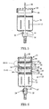
- FIG. 1 is a partial cross-sectional view of the hole saw assembly in accordance with the present invention
- FIG. 2 is a partial cross-sectional view of the one embodiment of the annular cutting ring member in accordance with the present invention
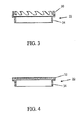
- FIG. 3 is a partial cross-sertional view of another embodiment of the annular cutting ring member in accordance with the present invention.
- FIG. 4 is a partial cross-sectional view of another embodiment of the annular cutting ring member in accordance with the present invention.
- FIG. 5 is a partial cross-sectional view of another embodiment of the hole saw assembly in accordance with the present invention.
- FIG. 6 is a partial cross-sectional view of the hole saw assembly shown in FIG. 1 further including two extension members positioned between the saw cup member and the annular cutting ring member in accordance with another embodiment of the present invention
- FIG. 7 is a partial cross-sectional view of the hole saw assembly shown in FIG. 5 further including two extension members positioned between the saw cup member and the annular cutting ring member in accordance with still another embodiment of the present invention
- FIG. 8 is an exploded side-elevation view of the locking groove member positioned in the distal open end of the saw cup member in accordance with one embodiment of the present invention.
- FIG. 9 is a partial cross-sectional view of the extension members illustrating that their outer diameter may be less than the outer diameter of the tubular saw cup member in accordance with the present invention.
- FIG. 10 is an enlarged partial cross-sectional view of the hole saw assembly of FIG. 6 taken within the broken line detail "10-10" in accordance with one embodiment of the present invention.
- FIG. 11 is an enlarged partial cross-sectional view of the hole saw assembly of FIG. 6 taken within the broken line detail "11-11" in accordance with another embodiment of the present invention.
- FIG. 1 there is shown a hole saw assembly 10, which includes a tubular saw cup member 12 having a threaded opening 13 in the proximal closed end 14 thereof.
- the proximal closed end 14 of the saw cup member 12 is structurally arranged to be engaged by a mandrel member 16 having a bore 17 therethrough and a threaded projection 19 thereon which secures the mandrel member to the saw cup member 12.
- a drill or pilot bit 18 is positioned in the bore of the mandrel member and secured thereto by a set screw 24 to couple the assembly to a drill or other power source (not shown).
- pilot bit 18 centrally extends beyond the annular cutting ring member 22 to engage the substrate workpiece to thereby guide and maintain proper alignment of the saw cup member 12 during the beginning of the substrate cutting operation.
- the saw cup member 12 includes a distal open end 20 having a plurality of threads 25 within the distal open end.
- the threads 25 are designed to receive complementary threads mounted to an annular cutting edge ring or member 22.
- FIGS. 2-4 various types of annular cutting ring members 22 are illustrated, with FIG. 2 illustrating an annular cutting blade member 28 having an internal annular chamfer 29 for cutting paper and fabrics, with FIG. 3 illustrating an annular cutting tooth member 30 for cutting wood, metal, sheet metal and plastics, and with FIG. 4 illustrating an annular grit edge cutting member 32 for cutting marble and granite.
- FIGS. 2-4 various types of annular cutting ring members 22 are illustrated, with FIG. 2 illustrating an annular cutting blade member 28 having an internal annular chamfer 29 for cutting paper and fabrics, with FIG. 3 illustrating an annular cutting tooth member 30 for cutting wood, metal, sheet metal and plastics, and with FIG. 4 illustrating an annular grit edge cutting member 32 for cutting marble and granite.
- FIGS. 1 various
- the ring members include reverse threads 34 which are engageable with the threads 25 positioned on to the distal open end 20 of the saw cup member 12.
- the cutting ring members may be composed of bi-metals and silicon carbide.
- the operator may select the appropriate annular cutting member for easy attachment to the distal open end of the saw cup member to provide a hole saw assembly which properly engages and cuts different types of substrate materials encountered.
- This permits the operator to select and mount several types of annular cutting members to a single sized saw cup member 12 thereby eliminating the necessity of having each sized saw cup member integrally secured to a specific configured annular cutting ring member.
- the operator of the hole saw assembly in accordance with the present invention encounters a wood substrate overlying a granite substrate, the operator would mount the annular cutting tooth member 30 by threading the member and the reverse threads 34 onto the threads 25 on the distal end 20 of the saw cup member 12 to engage and cut the wood substrate.
- the engagement and cutting of the substrate workpiece results from the kerf of the blade formed in the substrate workpiece which stabilizes the saw cup member during the cutting operation.
- the operator unscrews the cutting tooth member 30 from the distal end 20 of the saw cup member 12 and replaces the annular cutting tooth member 30 with an annular grit edge cutting member 32 to engage and to cut the granite substrate workpiece.
- each saw cup member has a permanently mounted annular cutting ring member mounted to the distal end 20. Additionally, when the annular cutting ring member becomes worn or damaged, the entire saw cup member does not need to be discarded. It is only necessary to replace the worn or damaged annular cutting ring member. Thus, the only consumable parts in the present invention are the annular cutting ring member and the pilot bit.
- the hole saw assembly 10 is similar to the hole saw assembly shown in FIG. 1 except that the mandrel member 16 is welded to the proximal closed end 14 of the tubular saw cup member 12.
- the mandrel member 16 contains a bore 17 therein for mounting the drill or pilot bit 18 that extends beyond the annular cutting ring member 22 to engage the substrate workpiece and maintain proper alignment of the cup member on the substrate during the beginning of the cutting operation.
- the mandrel member 16 couples the saw cup assembly 10 to a drill or other power source (not shown), as is known in the art.
- annular cutting ring member 22 is mounted to the distal open end 20 of the saw cup member 12 by a locking pin member 36 which is engageable with a groove 37 positioned in side wall 26 of the cup member at the distal open end of the saw cup member.
- the locking member 36 engages the groove 37, as shown in FIG. 8 , the annular cutting ring member 22 is locked to the saw cup member when the assembly is operated in the cutting direction to secure the cutting ring member to the saw cup member.
- FIGS. 6 and 7 illustrate a further embodiment of the present invention wherein the hole saw assembly may include at least one saw cup extension member 40 which is positioned between the annular cutting ring member 22 and the distal open end 20 of the saw cup member 12. As shown in FIGS. 6 and 7 , two saw cup extension members 40 are provided to permit adjustment of the length of the saw cup member 12 to properly cut substrate materials having variable thicknesses. This eliminates the costly expenditure of maintaining an inventory of saw cup members each having a different length to properly engage and cut the particular thickness of the substrate encountered.
- the saw cup extension members 40 include a distal open end 20 having a plurality of threads 25 and a proximal end 14 having threads 34 thereon which are engageable with either the annular cutting ring member 22 and the reverse threads 34 thereon or the threads 25 on the distal end 20 of either the extension member or members or the saw cup member. This permits the tightening of the annular cutting ring member 22 and the tightening of the extension members 40 to the open end 20 of the saw cup member during the rotation of the assembly while cutting the substrate. As shown in FIG.
- the saw cup extension members 40 may be of the same length; however, it is within the scope of the present invention that the extension members 40 may be of different lengths to permit the operator to appropriately select the length of the saw cup member that engages and cuts the thickness of the substrate encountered.
- the hole saw assembly 10 includes a tubular saw cup member 12 which is identical to the hole saw assembly described in FIG. 1 , supra .
- the operator may insert between the annular cutting ring member 22 and distal open end 20 of the saw cup member 12 one or more saw cup extension members 40 to obtain the appropriate length saw cup to properly engage and cut the work piece substrate encountered.
- the hole saw assembly is adjustable in length and provides a significant cost savings to the operator with the only consumable parts being the cutting ring member and the pilot bit.
- the saw cup extension members 40 include a distal open end 20 having a plurality of groove members 3 7 and a proximal end 14 having locking pin members 3 6 extending therefrom which are engageable with one another to lock together the annular cutting ring member 22 and the extension member or members of the saw cup member. This permits the tightening of the assembly including the cutting ring member 20 and the extension members 40 during rotation of the assembly during the cutting operation.
- the saw cup extension members 40 may be of the same length; however, it is within the scope of the present invention that the extension members 40 may be of different lengths to permit the operator to appropriately select the length of the saw cup member that engages and cuts the thickness of the substrate encountered.
- the hole saw assembly 10 includes a tubular saw cup member 12 which is identical to the hold saw assembly described in FIG. 5 , supra .
- the operator may insert between the annular cutting ring member 22 and distal open end 20 of the saw cup member 12 one or more saw cup extension members 40 to obtain the appropriate length saw cup to properly engage and cut the work piece substrate encountered.
- the hole saw assembly is adjustable in length and provides a significant cost savings to the operator with the only consumable parts being the cutting ring member and the pilot bit.
- FIG. 9 illustrates a further embodiment of the present invention, as shown in FIGS. 1 , 5 and 6 .
- the shoulder 23 on the cutting ring member 22 and the shoulder 42 on the extension members 40 both include a chamfer 27 therearound which permits the easy reversal of the cutting ring member 22 from the extension members 40.
- the distal open end 20 of the saw cup member 12 includes a chamfer 27 therearound which permits the easy reversal and detachment of the cutting ring 22 from the distal end of the saw cup member 12.
- Such a structure prevents mating of the saw cup, the ring member and or the extension members and facilitates the easy detachment or uncoupling of the parts from one another.
- FIG. 11 is a view similar to FIG. 10 wherein the shoulder 42 on the extension members 40 includes an undercut notch 44.
- the undercut notch 44 prevents mating of the several parts to one another and permits the easy detachment or uncoupling of the parts from one another.
- the outer diameter of the annular cutting ring member 22 and the saw cup extension members may be less than the outer diameter of the tubular saw cup member to reduce the friction and heat during the cutting operation as well as permitting the cut debris to escape to provide longer life to the assembly and more rapid cutting by the assembly through the substrate material.
- the saw cup member may have fluted openings 15 to facilitate removal of the cut substrate from the hole saw assembly.
Landscapes
- Engineering & Computer Science (AREA)
- Mechanical Engineering (AREA)
- Processing Of Stones Or Stones Resemblance Materials (AREA)
- Drilling Tools (AREA)
- Sawing (AREA)
Applications Claiming Priority (1)
| Application Number | Priority Date | Filing Date | Title |
|---|---|---|---|
| US23798009P | 2009-08-28 | 2009-08-28 |
Publications (1)
| Publication Number | Publication Date |
|---|---|
| EP2289656A1 true EP2289656A1 (fr) | 2011-03-02 |
Family
ID=43084457
Family Applications (1)
| Application Number | Title | Priority Date | Filing Date |
|---|---|---|---|
| EP10008942A Withdrawn EP2289656A1 (fr) | 2009-08-28 | 2010-08-27 | Ensemble de scie-cloche à profondeur ajustable |
Country Status (4)
| Country | Link |
|---|---|
| US (1) | US20110052340A1 (fr) |
| EP (1) | EP2289656A1 (fr) |
| CA (1) | CA2713904A1 (fr) |
| MX (1) | MX2010009510A (fr) |
Cited By (4)
| Publication number | Priority date | Publication date | Assignee | Title |
|---|---|---|---|---|
| CN103417341A (zh) * | 2013-08-28 | 2013-12-04 | 徐小山 | 一种肢体固定用树脂石膏高效定深钻孔装置 |
| FR3021570A1 (fr) * | 2014-05-28 | 2015-12-04 | Diamoutils | Outil de percage |
| EP3501710A1 (fr) * | 2017-12-21 | 2019-06-26 | Hilti Aktiengesellschaft | Section de coupe pour une couronne de forage |
| WO2023158054A1 (fr) * | 2022-02-16 | 2023-08-24 | 임형국 | Carottier |
Families Citing this family (14)
| Publication number | Priority date | Publication date | Assignee | Title |
|---|---|---|---|---|
| US20080181735A1 (en) * | 2007-01-25 | 2008-07-31 | Ting Fong Electric & Machinery Co., Ltd. | Method for manufacturing drill cutters and structure thereof |
| US10137507B2 (en) | 2010-01-13 | 2018-11-27 | Irwin Industrial Tool Company | Hole cutter with multiple fulcrums |
| US9782839B2 (en) | 2010-01-13 | 2017-10-10 | Irwin Industrial Tool Company | Hole cutter with chip egress aperture |
| US9808869B2 (en) * | 2010-01-13 | 2017-11-07 | Irwin Industrial Tool Company | Hole cutter with chip egress aperture |
| US9724766B2 (en) | 2010-01-13 | 2017-08-08 | Irwin Industrial Tool Company | Hole cutter with multiple fulcrums |
| US9884374B2 (en) | 2015-09-03 | 2018-02-06 | Irwin Industrial Tool Company | Hole cutter with multiple fulcrums |
| WO2014015154A1 (fr) | 2012-07-18 | 2014-01-23 | Milwaukee Electric Tool Corporation | Scie cylindrique |
| US9597736B2 (en) | 2013-12-19 | 2017-03-21 | Milwaukee Electric Tool Corporation | Adjustable diameter hole cutter |
| US9815124B1 (en) | 2016-03-22 | 2017-11-14 | Flamur Tulovic | Hole saw with threadably removable portion |
| WO2020014340A1 (fr) | 2018-07-10 | 2020-01-16 | Milwaukee Electric Tool Corporation | Scie-cloche dotée de trous à parois latérales hexagonales |
| WO2020257303A1 (fr) | 2019-06-20 | 2020-12-24 | Milwaukee Electric Tool Corporation | Scie-cloche dotée de trous à parois latérales circulaires |
| USD958855S1 (en) | 2019-12-09 | 2022-07-26 | Milwaukee Electric Tool Corporation | Hole saw |
| USD1066442S1 (en) * | 2022-06-07 | 2025-03-11 | Apex Brands, Inc. | Self-feed bit |
| US12594612B2 (en) | 2023-01-21 | 2026-04-07 | Joseph Lutzker | Soffit saw and extension |
Citations (5)
| Publication number | Priority date | Publication date | Assignee | Title |
|---|---|---|---|---|
| JPS62111811U (fr) * | 1985-12-30 | 1987-07-16 | ||
| JPH09123157A (ja) * | 1995-11-01 | 1997-05-13 | Sanwa Daiyamondo Kogyo Kk | 大口径穴あけ装置および大口径穴あけ装置に用いられるホールソー |
| JP2007136643A (ja) * | 2005-11-22 | 2007-06-07 | Miyanaga:Kk | コアドリル |
| JP2008087433A (ja) * | 2006-10-05 | 2008-04-17 | Consec Corp | コアビット |
| WO2008058329A1 (fr) * | 2006-11-14 | 2008-05-22 | Kym John Keightley | Scie-cloche avec des lames de coupe interchangeables |
Family Cites Families (9)
| Publication number | Priority date | Publication date | Assignee | Title |
|---|---|---|---|---|
| US3262474A (en) * | 1964-03-11 | 1966-07-26 | Black | Hole saw assembly |
| US4303357A (en) * | 1980-05-19 | 1981-12-01 | William Makar | Quick-change hole saw mandrel |
| DE8901906U1 (de) * | 1989-02-17 | 1989-05-24 | Entwicklungszentrum für Zerspanungstechnik GmbH & Co KG, 7630 Lahr | Vorrichtung zum Entfernen beschädigter Stellen in Gummiteilen |
| JPH0747244B2 (ja) * | 1991-02-19 | 1995-05-24 | 株式会社ミヤナガ | コアドリル |
| US6705807B1 (en) * | 1999-11-24 | 2004-03-16 | Black & Decker Inc. | Hole saw and connection method |
| US6641338B2 (en) * | 2000-03-02 | 2003-11-04 | Roger J. Despres | Plug ejecting hole saw with interchangeable saw cups having different size attachment bores |
| JP4186713B2 (ja) * | 2003-05-29 | 2008-11-26 | マニー株式会社 | 根管治療器具及び製造方法 |
| US7246975B2 (en) * | 2005-05-18 | 2007-07-24 | Chris Corso | Hole saw with replaceable cutting tip |
| US7237984B1 (en) * | 2005-06-29 | 2007-07-03 | Guzda Thomas G | Hole-cutting saw |
-
2010
- 2010-08-27 CA CA2713904A patent/CA2713904A1/fr not_active Abandoned
- 2010-08-27 EP EP10008942A patent/EP2289656A1/fr not_active Withdrawn
- 2010-08-27 US US12/870,461 patent/US20110052340A1/en not_active Abandoned
- 2010-08-27 MX MX2010009510A patent/MX2010009510A/es unknown
Patent Citations (5)
| Publication number | Priority date | Publication date | Assignee | Title |
|---|---|---|---|---|
| JPS62111811U (fr) * | 1985-12-30 | 1987-07-16 | ||
| JPH09123157A (ja) * | 1995-11-01 | 1997-05-13 | Sanwa Daiyamondo Kogyo Kk | 大口径穴あけ装置および大口径穴あけ装置に用いられるホールソー |
| JP2007136643A (ja) * | 2005-11-22 | 2007-06-07 | Miyanaga:Kk | コアドリル |
| JP2008087433A (ja) * | 2006-10-05 | 2008-04-17 | Consec Corp | コアビット |
| WO2008058329A1 (fr) * | 2006-11-14 | 2008-05-22 | Kym John Keightley | Scie-cloche avec des lames de coupe interchangeables |
Cited By (5)
| Publication number | Priority date | Publication date | Assignee | Title |
|---|---|---|---|---|
| CN103417341A (zh) * | 2013-08-28 | 2013-12-04 | 徐小山 | 一种肢体固定用树脂石膏高效定深钻孔装置 |
| FR3021570A1 (fr) * | 2014-05-28 | 2015-12-04 | Diamoutils | Outil de percage |
| EP3501710A1 (fr) * | 2017-12-21 | 2019-06-26 | Hilti Aktiengesellschaft | Section de coupe pour une couronne de forage |
| WO2019121138A1 (fr) * | 2017-12-21 | 2019-06-27 | Hilti Aktiengesellschaft | Section de découpage pour une couronne de forage |
| WO2023158054A1 (fr) * | 2022-02-16 | 2023-08-24 | 임형국 | Carottier |
Also Published As
| Publication number | Publication date |
|---|---|
| CA2713904A1 (fr) | 2011-02-28 |
| MX2010009510A (es) | 2011-05-04 |
| US20110052340A1 (en) | 2011-03-03 |
Similar Documents
| Publication | Publication Date | Title |
|---|---|---|
| US20110052340A1 (en) | Adjustable Depth Hole Saw Assembly | |
| US7073992B2 (en) | Arbor for hole cutter and related method of use | |
| US7850405B2 (en) | Hole saw boss | |
| US20220097150A1 (en) | Hole saw arbor assembly | |
| EP2252421B1 (fr) | Scie-cloche à changement rapide et arbre porte-outil | |
| US9751135B1 (en) | Quick release hole saw | |
| US11103934B2 (en) | Hole cutter with multiple fulcrums | |
| EP3608046A1 (fr) | Scie-cloche comprenant une ouverture allongée axialement délimitant des points d'appui multiples | |
| US7600458B2 (en) | Reciprocating saw blade with tapered tang stem | |
| CN102006960B (zh) | 速换刀轴、孔刀及方法 | |
| US20110170969A1 (en) | Hole Cutter with Axially-Elongated Aperture Defining Multiple Fulcrums | |
| US20100080665A1 (en) | Hole saw with interchangeable cutting blades | |
| EP2800645B1 (fr) | Dispositif de scie-cloche ajustable en positions multiples, avec éjecteur de matériel découpé | |
| US20070166116A1 (en) | Hole cutter and guide | |
| US8753048B2 (en) | Hole saw | |
| US20090269155A1 (en) | Alignment Structure for a Wood Flat Drill Bit | |
| US20190039262A1 (en) | Hole saws | |
| US7384222B2 (en) | Hole saw | |
| US11701717B2 (en) | Hole cutter having plug ejection and method thereof | |
| US7049541B1 (en) | Cutting guide for plasma torch | |
| GB2393676A (en) | Bit attachment adapted to create a countersink chamfer |
Legal Events
| Date | Code | Title | Description |
|---|---|---|---|
| PUAI | Public reference made under article 153(3) epc to a published international application that has entered the european phase |
Free format text: ORIGINAL CODE: 0009012 |
|
| AK | Designated contracting states |
Kind code of ref document: A1 Designated state(s): AL AT BE BG CH CY CZ DE DK EE ES FI FR GB GR HR HU IE IS IT LI LT LU LV MC MK MT NL NO PL PT RO SE SI SK SM TR |
|
| AX | Request for extension of the european patent |
Extension state: BA ME RS |
|
| STAA | Information on the status of an ep patent application or granted ep patent |
Free format text: STATUS: THE APPLICATION IS DEEMED TO BE WITHDRAWN |
|
| 18D | Application deemed to be withdrawn |
Effective date: 20110903 |