EP2290870B1 - Verfahren zur Schätzung und Korrektur einer Taktabweichung zwischen den Uhren eines empfangenden Sende- und Empfangsgerätes und eines zugehörigen sendenden Sendegerätes, sowie Empfänger zum Implementieren des Verfahrens - Google Patents
Verfahren zur Schätzung und Korrektur einer Taktabweichung zwischen den Uhren eines empfangenden Sende- und Empfangsgerätes und eines zugehörigen sendenden Sendegerätes, sowie Empfänger zum Implementieren des Verfahrens Download PDFInfo
- Publication number
- EP2290870B1 EP2290870B1 EP09169176A EP09169176A EP2290870B1 EP 2290870 B1 EP2290870 B1 EP 2290870B1 EP 09169176 A EP09169176 A EP 09169176A EP 09169176 A EP09169176 A EP 09169176A EP 2290870 B1 EP2290870 B1 EP 2290870B1
- Authority
- EP
- European Patent Office
- Prior art keywords
- energy
- matrix
- radon
- clock
- drift
- Prior art date
- Legal status (The legal status is an assumption and is not a legal conclusion. Google has not performed a legal analysis and makes no representation as to the accuracy of the status listed.)
- Not-in-force
Links
- 238000000034 method Methods 0.000 title claims description 87
- 239000011159 matrix material Substances 0.000 claims description 122
- 229910052704 radon Inorganic materials 0.000 claims description 101
- SYUHGPGVQRZVTB-UHFFFAOYSA-N radon atom Chemical compound [Rn] SYUHGPGVQRZVTB-UHFFFAOYSA-N 0.000 claims description 101
- 238000001514 detection method Methods 0.000 claims description 14
- 238000009826 distribution Methods 0.000 claims description 10
- 238000005070 sampling Methods 0.000 claims description 8
- 238000012935 Averaging Methods 0.000 claims description 6
- 230000010354 integration Effects 0.000 claims description 6
- 230000001131 transforming effect Effects 0.000 claims description 4
- 230000003111 delayed effect Effects 0.000 claims description 2
- 238000012545 processing Methods 0.000 description 9
- 230000001427 coherent effect Effects 0.000 description 8
- 238000007476 Maximum Likelihood Methods 0.000 description 6
- 238000004891 communication Methods 0.000 description 4
- 238000012937 correction Methods 0.000 description 4
- 238000006073 displacement reaction Methods 0.000 description 4
- 238000003909 pattern recognition Methods 0.000 description 4
- 230000009466 transformation Effects 0.000 description 4
- 238000013461 design Methods 0.000 description 3
- 238000003708 edge detection Methods 0.000 description 3
- 230000007246 mechanism Effects 0.000 description 3
- 238000007781 pre-processing Methods 0.000 description 3
- 230000008569 process Effects 0.000 description 3
- 230000011664 signaling Effects 0.000 description 3
- 230000008901 benefit Effects 0.000 description 2
- 238000004422 calculation algorithm Methods 0.000 description 2
- 230000008859 change Effects 0.000 description 2
- 230000000694 effects Effects 0.000 description 2
- 238000001914 filtration Methods 0.000 description 2
- 230000006870 function Effects 0.000 description 2
- 238000013459 approach Methods 0.000 description 1
- 230000006399 behavior Effects 0.000 description 1
- 230000005540 biological transmission Effects 0.000 description 1
- 238000004364 calculation method Methods 0.000 description 1
- 230000006835 compression Effects 0.000 description 1
- 238000007906 compression Methods 0.000 description 1
- 238000002591 computed tomography Methods 0.000 description 1
- 239000012141 concentrate Substances 0.000 description 1
- 238000010276 construction Methods 0.000 description 1
- 230000001186 cumulative effect Effects 0.000 description 1
- 238000005315 distribution function Methods 0.000 description 1
- 230000007613 environmental effect Effects 0.000 description 1
- 230000002349 favourable effect Effects 0.000 description 1
- 238000010191 image analysis Methods 0.000 description 1
- 238000002955 isolation Methods 0.000 description 1
- 238000005304 joining Methods 0.000 description 1
- 238000004519 manufacturing process Methods 0.000 description 1
- 230000000116 mitigating effect Effects 0.000 description 1
- 238000012544 monitoring process Methods 0.000 description 1
- 230000000737 periodic effect Effects 0.000 description 1
- 230000009467 reduction Effects 0.000 description 1
- 230000003595 spectral effect Effects 0.000 description 1
- 230000001360 synchronised effect Effects 0.000 description 1
- 230000002123 temporal effect Effects 0.000 description 1
- 238000012360 testing method Methods 0.000 description 1
Images




Classifications
-
- H—ELECTRICITY
- H04—ELECTRIC COMMUNICATION TECHNIQUE
- H04L—TRANSMISSION OF DIGITAL INFORMATION, e.g. TELEGRAPHIC COMMUNICATION
- H04L7/00—Arrangements for synchronising receiver with transmitter
- H04L7/0054—Detection of the synchronisation error by features other than the received signal transition
Definitions
- the present invention relates to a clock offset tracking and synchronization method suitable for low-complexity receivers communicating via impulse-radio ultra-wideband (IR-UWB) radio transmission or other pulse based signals.
- IR-UWB impulse-radio ultra-wideband
- the invention concerns a method for estimating and correcting a drift between the clocks of transceivers that communicate via electromagnetic signals.
- this method applies when two electronic devices communicate without having a common reference clock, but each device has its own free running clock. This method is of particular interest in low-cost, low complexity devices where high precision oscillators cannot be used to generate the clock.
- IEEE 802.15.4 [1] targets low data rate wireless networks with extensive battery life and very low complexity. Its physical layer is based on a narrowband radio, operating in the unlicensed ISM band around 2.4 GHz. IEEE 802.15.4a [2] is an amendment to the 802.15.4 specification. It adds an impulse-radio ultra-wide band (IR-UWB) physical layer operating in several bands of 500 MHz (and 1.5 GHz) from approximately 3 GHz to 10 GHz. This physical layer should offer a better robustness against interference and multipath propagation channels, a higher data rate, and the possibility to perform ranging between devices.
- IR-UWB impulse-radio ultra-wide band
- information exchange in 802.15.4 is packet based.
- the bits to be sent are grouped into packets that are sent individually from the transmitter to the receiver over the wireless medium.
- a receiver In order to retrieve the bits from a packet, a receiver has to perform a certain number of tasks. First, the receiver has to actually detect the presence of the packet and subsequently determine where this packet begins. This process is commonly referred to as “packet detection and timing acquisition” or “synchronization”. It generally relies on the presence of a so called “preamble” appended before the payload (the data bits). This preamble is known in advance to the receiver.
- the receiver knows where to look for the unknown payload and can perform "demodulation and decoding" to recover it. Often, the receiver also performs a "channel estimation” step between synchronization and decoding to gain some knowledge about the statistics of the communication channel. This knowledge is then used to enhance the performance of demodulation and decoding.
- Networks such as 802.15.4 networks are asynchronous networks. There is no common reference clock in the system. Rather, every device has its own free running clock. Furthermore, because the design objective of 802.15.4 devices is low-cost, low-power and low complexity, high precision oscillators cannot be used to generate the clock on these devices. Cheap oscillators available today have a precision of about ⁇ 20 ppm (parts per million). This implies that the clocks of two devices do not run at the exact same speed and may thus differ slightly; after some time they drift apart from each other. Consequently, in an asynchronous network with free running clocks, packet detection and timing acquisition has to be obtained for every packet individually.
- clock offset tracking is needed to maintain synchronization and compensate for clock drifts between a transmitter and a receiver.
- synchronization and clock offset tracking are especially challenging because the fine temporal resolution of UWB signals requires high timing accuracies.
- multi-user interference between devices of the same network or neighboring networks starts to severely limit the network performance. It is therefore highly desirable that a receiver performs all the tasks needed to receive a packet in such a way as to limit the impact of MUI as much as possible.
- Patent applications [10], [11] are addressing ranging applications. In particular, they concentrate on the estimation of the time of arrival (TOA).
- TOA time of arrival
- the techniques proposed in [10], [11] construct an energy matrix for the problem of TOA estimation in ranging applications.
- the Hough transform as well as the more general Radon transform are well-established techniques from computer vision and image processing.
- the Hough transform for example, goes back to a patent from 1962 [12] and the ⁇ , ⁇ parameterization used widely today goes back to a paper published in 1972 [8]. Since then, there has been a large body of literature as well as patents related to the Radon/Hough transform. Most of these publications relate to applications requiring classical pattern recognition task in images (for example in computer tomography or radar applications) or they deal with ways to compute the transforms and their inverses in efficient ways.
- the publication " Invariant Radon-Wavelet Packet Signatures for Pattern Recognition" from Chen G Y et Al.
- Patent application [13] and the corresponding paper [14] describe a maximum likelihood estimator for clock drift estimation in a coherent or non-coherent IR-UWB low data-rate (LDR) receiver. Only clock drift estimation assuming perfect synchronization and channel estimation is treated. Several samples from the receiver are accumulated and yield nodes of a trellis on which the best path is calculated to yield the maximum likelihood estimate. Tracking and compensating for the drift is not treated, neither is it explained how to achieve synchronization and channel estimation.
- LDR low data-rate
- Patent application [4] and its companion paper [15] contain a synchronization method that is robust to MUI.
- the method is for the synchronization of coherent receivers and has no notion of energy matrix whatsoever.
- its basic principle for rejecting interference which is the proposed power independent detection method, can be applied to the received signal prior to placing it in the energy matrix and transforming it via the Radon/Hough transform in order to reject interference.
- Patent application [3] and the corresponding conference paper [16] contain methods to reject interference in a non-coherent IR-UWB receiver.
- the methods described therein can be used for interference mitigation also during the clock offset tracking method once the channel estimation has been performed.
- the patent application US2006/158358 describes a method for determining the phase displacement between two signals. This method is particularly suited to detect a phase displacement between an expected signal and a received signal. In order to use this method, the received signal has roughly the same shape and the same period as the input signal.
- This method comprises the following steps :
- the calculated slope enables determining the phase displacement between the measured signal and the expected signal.
- the method described in this document does not enable dealing with Multi-user interference. Moreover, the method for determining the drift is different from the method of the present invention.
- the object of the present invention is achieved by a method for estimating and correcting a drift between a local clock of a receiving transceiver and a remote clock of a corresponding emitting transceiver, said receiving transceiver receiving electromagnetic signals from the emitting transceiver, said method comprising the steps of :
- the object of the present invention is further achieved by a receiver that implements the method of the invention.
- the main pillars of this invention are the following:
- the invention is described in the context of a non-coherent receiving transceiver or receiver based on energy detection.
- the signaling model of the IEEE 802.15.4a preamble part is only done for simplicity and to serve as an example.
- Most of the concepts can be extended in a straightforward way to other receiver architectures (e.g. coherent), other signaling formats (e.g. the data part of an IEEE 802.15.4a packet or any other IR-UWB or pulse-based signaling format). Where an extension is not straightforward, we will comment on how it can be done.
- the present invention uses such method based on the Radon/Hough transform that fulfills exactly these requirements.
- Any line in the image can thus be mapped to one unique point (p, ⁇ ) in the Radon space.
- the Radon transform assigns to any ( ⁇ , ⁇ ) in the Radon space the value of the integral obtained by integrating along the line given by (5) in the original image.
- an initial Radon matrix is first defined.
- the energy of the received signal is sampled and the contribution of each sample is calculated.
- Each contribution is then added to the current Radon matrix, the first contribution being added to the initial Radon matrix.
- This initial Radon matrix could for example be a null matrix.
- Figure 9 shows a schema of how we obtain the Radon matrix.
- every sample of the receiver output corresponds to a coordinate (x k , y k ).
- This coordinate is the center coordinate of a pixel with a width of 1.
- the energy value y m of the corresponding sample is denoted by I(x k , y k ) and we call it the intensity of the pixel (x k , y k ).
- I(x k , y k ) the intensity of the pixel (x k , y k ).
- the intensity is uniformly spread over the whole pixel.
- densities could be a punctual or Gaussian density for example.
- the spacing ⁇ ⁇ i+1 - ⁇ i is a parameter given by the discretization scheme used and can be changed. The same holds for the spacing ⁇ .
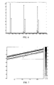
- Fig. 5 and Fig. 8 show the Radon matrix corresponding to the receiver output shown in Fig. 3 and Fig. 6 respectively.
- the range of ⁇ as well the range of ⁇ that is of interest to us is known. Therefore, we can calculate the Radon transform for only the points of interest, limiting both processing and memory requirements.
- the Radon matrix that we have to store has a constant size independent of the length of our observation.
- the Radon transform as a compression scheme that instead of the energy matrix yields an alternative matrix of smaller dimension that still preserves all the signal information that is necessary to do clock drift estimation.
- Figure 10 illustrates how to adapt the Radon transform after a correction of the drift. What we basically do is to transform the coordinate system in Radon space after a drift correction has occurred.
- the example shows the simplified case of a single line, but extension to the situation in Figure 9 with a small band is straightforward.
- ⁇ 1 that gets projected to ⁇ 1 according to equation (6).
- Equations 11 and 12 define the transformation we have to apply on the coordinate system. To be able to do this transformation, we just have to keep the two values and sin ⁇ i up to date.
- Synchronization and time of arrival (TOA) estimation deal with finding the first arriving multipath component of a signal. We can also achieve this in Radon space, again by looking at the column j max corresponding to the most likely clock drift.
- Coarse synchronization or estimation of the TOA of the strongest multipath component is achieved by determining the ⁇ value ⁇ max of the entry with maximal intensity in column j max of the Radon matrix. Given ⁇ , it is straightforward to calculate the corresponding time index through equation (5).
- For a finer synchronization or to find the TOA of the first multipath component we can employ any commonly used fine synchronization method that searches the first arriving path starting from the position of the strongest path. This can be done by a classical search-back procedure where entries in the column j max are searched in a window around ⁇ max and the one with the lowest ⁇ index that has significant energy is kept as an estimate of the TOA of the first multipath component.
- several samples are combined using a moving average operation prior to calculating the Radon transform.
- the moving average operation uses the median.
- the samples above a threshold are set to a common value prior to averaging.
- the thresholding operation from [3] can be applied to reject interference. This is done similarly to the method explained in ⁇ 10) to reject noise, only that this time samples above a threshold v 2 are rejected because they are likely to contain interference.
- v 2 is calculated similarly to v1 only that the central chi-square distribution with 2BTG degrees of freedom is replaced by a non-central chi-square distribution with 2BTG degrees of freedom and non centrality parameter ⁇ m with ⁇ m equal to the estimated channel energy of the m th sample.
- the averaging operation that combines G symbols may optionally be done using ordered statistics (e.g. the median) to improve robustness against outliers caused by interference.
- samples Prior to channel estimation, samples can be combined in a PID fashion (power independent detection method, see [4]).
- the preprocessing operation detailed in ⁇ 10) is applied, setting samples below v 1 to 0. Samples above v 1 are however all set to 1 such that they all contribute equally to the averaging process.
- the averaging operation is then performed over G binary samples and yields the input to the Radon transform.
- any other of the non linear filtering techniques proposed on the energy matrix by [7] and [6] can also be considered.
- IEEE 802.15.4 is a standard for low-power, low-complexity wireless personal area networks.
- the field of possible applications includes environmental monitoring, home automation, medical applications, industrial and building automation.
- the prices of the devices forming the network should be as cheap as possible.
- MUI multi-user interference
- the method of the invention cannot only be used for clock drift estimation and correction, but also for synchronization and channel estimation which are two other basic functions every device in the above mentioned wireless networks has to perform. Having one single method to solve most of the key problems in a low-complexity wireless receiver would obviously be of huge interest to any industrial player.
Landscapes
- Engineering & Computer Science (AREA)
- Computer Networks & Wireless Communication (AREA)
- Signal Processing (AREA)
- Synchronisation In Digital Transmission Systems (AREA)
- Radar Systems Or Details Thereof (AREA)
Claims (26)
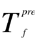
- Verfahren zum Schätzen und Korrigieren einer Abweichung zwischen einer lokalen Uhr eines empfangenden Transceivers und einer fernen Uhr eines entsprechenden sendenden Transceivers, wobei der empfangende Transceiver von dem sendenden Transceiver elektromagnetische Signale empfängt, mit folgenden Phasen:- Empfang eines Signals durch den empfangenden Transceiver, das von dem sendenden Transceiver ausgestrahlt wird und aus mindestens einem Symbol besteht, wobei jedes Symbol innerhalb eines Zeitrahmens mit einer ersten Dauer
 - Entnahme von Proben der Energie des empfangenen Signals über eine Vielzahl der Zeitrahmen;- Bildung einer Matrix, die die Energie des Signals der Proben repräsentiert;- Bestimmung von Punkten maximaler Energie innerhalb jedes Zeitrahmens mithilfe der Energiematrix;
Bestimmung einer Geraden, die eine Vielzahl der Punkte maximaler Energie verbindet, durch Verwendung einer Linienerkennungsmethode, wobei besagte Linienerkennungsmethode folgende Phasen umfasst:• Umwandlung der Linien der Energiematrix in Punkte eines Radonraums, wobei die Koordinaten (ρ,θ) eines Punktes in besagtem Radonraum einer schrägen Linie θ fern vom Ursprung ρ in besagter Energiematrix entsprechen;• Integrieren der Energie entlang jeder Linie der Energiematrix und Zuordnung eines Energiewerts entsprechend der integrierten Energie zu dem entsprechenden Punkt des Radonraums und Erhalten einer Radonmatrix;• Bestimmung mindestens eines Punkts mit maximalem Energiewert in der Radonmatrix;• Bestimmung einer Spalte der Radonmatrix, die der geschätzten Clock drift entspricht und mindestens einen des mindestens eines Punktes mit maximalem Energiewert enthält,- Bestimmung einer Schräge der Geraden;- Berechnung einer Zeitabweichung zwischen der Uhr des sendenden Transceivers und der Uhr des empfangenden Transceivers durch Verwendung der Schräge der Geraden;- Einstellung der Frequenz der Uhr des empfangenden Transceivers entsprechend der berechneten Zeitabweichung. - Verfahren nach Anspruch 1, wobei die Phase der Bildung des Energiematrix die Phase des Einführens zweier aufeinanderfolgender Werte der Energie, die durch die Entnahme von Proben des empfangenen Signals erhalten werden, in zwei aufeinanderfolgende Einträge einer Spalte der Energiematrix umfasst.
- Verfahren nach Anspruch 1, wobei die Phase der Bildung des Energiematrix die Phase des Einführens zweier Werte der Energie, die durch Entnahme von Proben des empfangenen Signals erhalten wurde, die um ein
Vielfaches der ersten Dauer
- Verfahren nach Anspruch 1, wobei die Werte der Radonmatrix mit einem Vektor von vorherbestimmter Länge gefaltet werden.
- Verfahren nach Anspruch 1 oder 4, wobei die Phase der Bestimmung des mindestens einen Höchstwertpunkts in dem Radonraum eine Phase des Mit-sich-selbst-Multiplizierens der Intensitätswerte der Radonmatrix umfasst.
- Verfahren nach Anspruch 1, wobei die Integration der Energie ausgeführt wird unter der Annahme dass die Energie in jeder Zelle der Energiematrix entsprechend einer spezifischen Verteilung verteilt ist.
- Verfahren nach Anspruch 6, wobei besagte spezifische Verteilung einer der folgenden entspricht:- die gesamte Energie in einer Zelle befindet sich in der Mitte der Zelle der Energiematrix;- die Energie ist gleichmäßig in der Zelle der Energiematrix verteilt; oder- es gibt eine Gaußsche Verteilung der Energie in der Zelle der Energiematrix.
- Verfahren nach Anspruch 1, wobei Messergebnisse unterhalb einer Schwelle vor der Berechnung der Radontransformierten aussortiert werden.
- Verfahren nach Anspruch 1, wobei Messergebnisse oberhalb einer Schwelle vor der Berechnung der Radontransformierten aussortiert werden.
- Verfahren nach Anspruch 1, wobei die Säule der Radonmatrix, die der geschätzten Clock drift entspricht, benutzt wird, um eine Schätzung des Kanalenergie-Verzögerungsprofils zu bestimmen.
- Verfahren nach Anspruch 1, wobei der Punkt der Radonmatrix mit dem Höchstwert als grobe Schätzung der Ankunftszeit des Signals benutzt wird.
- Verfahren nach Anspruch 11, wobei die geschätzte Ankunftszeit durch eine Rückwärtssuche verfeinert wird, ausgehend von der groben Schätzung der Ankunftszeit.
- Verfahren nach Anspruch 1, wobei besagte Matrix, die die Energie des erfassten Signals repräsentiert, eine Radonmatrix ist, und wobei das Verfahren des weiteren folgende Phasen umfasst:- Berechnung, für jede Energieprobe, eines Beitrags dieser Probe zu einem Eintrag der Radonmatrix;- Aktualisierung der Radonmatrix durch Hinzufügen besagten Beitrags;- Bestimmung mindestens eines Punkts mit maximalem Energiewert in dem Radonraum;- Bestimmung einer Spalte der Radonmatrix, die mindestens einen des mindestens eines Punktes mit maximalem Energiewert enthält;- Berechnung einer Zeitabweichung zwischen der Uhr des sendenden Transceivers und der Uhr des empfangenden Transceivers durch Verwendung der bestimmten Spalte der Radonmatrix;- Einstellung der Frequenz der Uhr des empfangenden Transceivers entsprechend der berechneten Zeitabweichung.
- Verfahren nach Anspruch 13, wobei die Werte des Radonraums mit einem Vektor vorherbestimmter Länge gefaltet werden.
- Verfahren nach Anspruch 14, wobei die Phase der Bestimmung des besagten mindestens einen Höchstwertpunkts in dem Radonraum eine Phase des Mit-sich-selbst-Multiplizierens der Intensitätswerte der Radonmatrix umfasst.
- Verfahren nach Anspruch 13, wobei die Integration der Energie unter der Annahme ausgeführt wird, dass die Energie in jeder Zelle der Energiematrix entsprechend einer spezifischen Verteilung verteilt ist.
- Verfahren nach Anspruch 16, wobei besagte spezifische Verteilung einer der folgenden entspricht:- die gesamte Energie in einer Zelle befindet sich in der Mitte der Zelle der Energiematrix;- die Energie ist in der Zelle der Energiematrix gleichmäßig verteilt; oder- es gibt eine Gaußsche Verteilung der Energie in der Zelle der Energiematrix.
- Verfahren nach Anspruch 13, wobei Messergebnisse unterhalb einer Schwelle vor der Berechnung der Radontransformierten aussortiert werden.
- Verfahren nach Anspruch 13, wobei Messergebnisse oberhalb einer Schwelle vor der Berechnung der Radontransformierten aussortiert werden.
- Verfahren nach Anspruch 13, wobei mehrere Proben unter Verwendung einer gleitenden Mittelwertoperation vor der Berechnung der Radontransformierte kombiniert werden.
- Verfahren nach Anspruch 20, wobei die gleitende Mittelwertoperation den Medianwert verwendet.
- Verfahren nach Anspruch 20, wobei Messergebnisse oberhalb einer Schwelle auf einen gemeinsamen Wert eingestellt werden, bevor man den Mittelwert berechnet.
- Verfahren nach Anspruch 13, wobei die Spalte der Radonmatrix, die der geschätzten Clock drift entspricht, benutzt wird, um das Kanalenergie-Verzögerungsprofil zu schätzen.
- Verfahren nach Anspruch 13, wobei der Punkt der Radontransformierten mit Höchstwert als grobe Schätzung der Ankunftszeit des Signals benutzt wird.
- Verfahren nach Anspruch 24, wobei die geschätzte Ankunftszeit durch eine Rückwärtssuche verfeinert wird, ausgehend von der groben Schätzung der Ankunftszeit.
- Empfänger zur Implementierung des Verfahrens nach einem beliebigen der Ansprüche 1-25.
Priority Applications (2)
| Application Number | Priority Date | Filing Date | Title |
|---|---|---|---|
| EP09169176A EP2290870B1 (de) | 2009-09-01 | 2009-09-01 | Verfahren zur Schätzung und Korrektur einer Taktabweichung zwischen den Uhren eines empfangenden Sende- und Empfangsgerätes und eines zugehörigen sendenden Sendegerätes, sowie Empfänger zum Implementieren des Verfahrens |
| US12/874,052 US8396175B2 (en) | 2009-09-01 | 2010-09-01 | Method for estimating and correcting a drift between clocks of receiving transceiver and a corresponding emitting transceiver, and receive for implementing said method |
Applications Claiming Priority (1)
| Application Number | Priority Date | Filing Date | Title |
|---|---|---|---|
| EP09169176A EP2290870B1 (de) | 2009-09-01 | 2009-09-01 | Verfahren zur Schätzung und Korrektur einer Taktabweichung zwischen den Uhren eines empfangenden Sende- und Empfangsgerätes und eines zugehörigen sendenden Sendegerätes, sowie Empfänger zum Implementieren des Verfahrens |
Publications (2)
| Publication Number | Publication Date |
|---|---|
| EP2290870A1 EP2290870A1 (de) | 2011-03-02 |
| EP2290870B1 true EP2290870B1 (de) | 2012-12-05 |
Family
ID=42111865
Family Applications (1)
| Application Number | Title | Priority Date | Filing Date |
|---|---|---|---|
| EP09169176A Not-in-force EP2290870B1 (de) | 2009-09-01 | 2009-09-01 | Verfahren zur Schätzung und Korrektur einer Taktabweichung zwischen den Uhren eines empfangenden Sende- und Empfangsgerätes und eines zugehörigen sendenden Sendegerätes, sowie Empfänger zum Implementieren des Verfahrens |
Country Status (2)
| Country | Link |
|---|---|
| US (1) | US8396175B2 (de) |
| EP (1) | EP2290870B1 (de) |
Families Citing this family (11)
| Publication number | Priority date | Publication date | Assignee | Title |
|---|---|---|---|---|
| US9397396B2 (en) * | 2009-04-01 | 2016-07-19 | Kathrein-Werke Kg | Radio system and a method for relaying packetized radio signals |
| US8731005B2 (en) * | 2009-10-12 | 2014-05-20 | Kathrein-Werke Kg | Absolute timing and Tx power calibration of the Tx path in a distributed system |
| US8599861B2 (en) * | 2010-06-03 | 2013-12-03 | Kathrein-Werke Kg | Active antenna array and method for relaying radio signals |
| US8774196B2 (en) | 2010-06-03 | 2014-07-08 | Kathrein-Werke Kg | Active antenna array and method for relaying radio signals with synchronous digital data interface |
| WO2014009981A1 (en) | 2012-07-12 | 2014-01-16 | Datalogic S.P.A. | Synchronization of a real-time uwb locating system |
| CN107113073A (zh) * | 2014-12-16 | 2017-08-29 | 罗伯特·博世有限公司 | 同步网络设备的时钟的方法 |
| US9680632B2 (en) * | 2015-02-12 | 2017-06-13 | Qualcomm Incorporated | Systems and methods for symbol time tracking |
| EP3282597A1 (de) | 2016-08-12 | 2018-02-14 | Fraunhofer-Gesellschaft zur Förderung der angewandten Forschung e.V. | Kommunikationssystem und sender |
| US10495737B1 (en) | 2019-02-07 | 2019-12-03 | Clairvoyant Networks, LLC | Methods, systems, and computer readable media for time-slotted ultra-wide-band object tracking |
| US10567035B1 (en) | 2019-03-06 | 2020-02-18 | Clairvoyant Networks, LLC | Methods, systems, and computer readable media for distribution of time synchronization information to ultra-wide-band devices |
| US10484833B1 (en) | 2019-04-12 | 2019-11-19 | Clairvoyant Networks, LLC | Methods, systems and computer readable media for providing and using ultra wideband local area networks (LANs) |
Family Cites Families (18)
| Publication number | Priority date | Publication date | Assignee | Title |
|---|---|---|---|---|
| US3069654A (en) | 1960-03-25 | 1962-12-18 | Paul V C Hough | Method and means for recognizing complex patterns |
| KR100459879B1 (ko) * | 1998-04-20 | 2005-01-15 | 삼성전자주식회사 | 비선형 신호 수신기 |
| AU2001247865A1 (en) | 2000-03-29 | 2001-10-15 | Time Domain Corporation | System and method of using multiple correlator receivers in an impulse radio system |
| US20020061081A1 (en) | 2000-10-13 | 2002-05-23 | Richards James L. | Method and system for reducing potential interference in an impulse radio |
| US6954480B2 (en) | 2001-06-13 | 2005-10-11 | Time Domain Corporation | Method and apparatus for improving received signal quality in an impulse radio system |
| JP4047764B2 (ja) | 2003-05-13 | 2008-02-13 | 株式会社東芝 | 情報記憶媒体、情報再生装置、情報再生方法 |
| KR100800368B1 (ko) | 2004-01-02 | 2008-02-04 | 인터내셔널 비지네스 머신즈 코포레이션 | 임펄스 무선(uwb) 채널 세트에서의 전송 신호 수신방법, 수신기 및 데이터 전송 시스템 |
| US7613257B2 (en) | 2004-10-29 | 2009-11-03 | Ecole Polytechnique Federale De Lausanne | Synchronizing method for impulse radio network |
| KR100641328B1 (ko) | 2004-12-24 | 2006-11-01 | 삼성전자주식회사 | 타이밍 복원 방법 및 타이밍 복원 장치 |
| WO2006112831A1 (en) | 2005-04-15 | 2006-10-26 | Mitsubishi Electric Research Laboratories | Method and system for estimating time of arrival of signals using multiple different time scales |
| US7684473B2 (en) * | 2005-06-01 | 2010-03-23 | Qualcomm Incorporated | Receiver for wireless communication network with extended range |
| US20090170458A1 (en) | 2005-07-19 | 2009-07-02 | Molisch Andreas F | Method and Receiver for Identifying a Leading Edge Time Period in a Received Radio Signal |
| US7526048B2 (en) | 2005-08-11 | 2009-04-28 | Mitsubishi Electric Research Laboratories, Inc. | Energy threshold selection for UWB TOA estimation |
| KR100981542B1 (ko) * | 2005-11-30 | 2010-09-10 | 삼성전자주식회사 | 직교 주파수 분할 다중화 시스템에서의 주파수 복원 장치 및 방법 |
| JP4585438B2 (ja) * | 2005-12-06 | 2010-11-24 | 富士通株式会社 | タイミング再生回路 |
| EP1903702A1 (de) | 2006-09-19 | 2008-03-26 | STMicroelectronics N.V. | Verfahren und Vorrichtung zur Schätzung der Drift zwichen zwei Takten, insbesondere zur Abstandsmessung in der UWB-LDR Technik |
| WO2009098652A1 (en) | 2008-02-08 | 2009-08-13 | Ecole Polytechnique Federale De Lausanne (Epfl) | Method for retrieving data from ultra wideband radio transmission signals and receiver implementing said method |
| US8306132B2 (en) * | 2009-04-16 | 2012-11-06 | Advantest Corporation | Detecting apparatus, calculating apparatus, measurement apparatus, detecting method, calculating method, transmission system, program, and recording medium |
-
2009
- 2009-09-01 EP EP09169176A patent/EP2290870B1/de not_active Not-in-force
-
2010
- 2010-09-01 US US12/874,052 patent/US8396175B2/en not_active Expired - Fee Related
Also Published As
| Publication number | Publication date |
|---|---|
| US8396175B2 (en) | 2013-03-12 |
| EP2290870A1 (de) | 2011-03-02 |
| US20110051847A1 (en) | 2011-03-03 |
Similar Documents
| Publication | Publication Date | Title |
|---|---|---|
| EP2290870B1 (de) | Verfahren zur Schätzung und Korrektur einer Taktabweichung zwischen den Uhren eines empfangenden Sende- und Empfangsgerätes und eines zugehörigen sendenden Sendegerätes, sowie Empfänger zum Implementieren des Verfahrens | |
| AU2007234292B2 (en) | Method and system for information transmission | |
| CN102332933B (zh) | 短时突发扩频信号传输与接收方法 | |
| US8831070B2 (en) | Method and apparatus for start of frame delimiter detection | |
| EP3799319B1 (de) | Systeme und verfahren zur auswahl einer ultrabreitbandigen präambel gemäss den umgebungsbedingung | |
| US8594018B2 (en) | Ranging for wireless radio frequency communication devices | |
| CN100530992C (zh) | 脉冲幅度调制-脉冲位置调制的信号的健壮非相干接收机 | |
| WO2010022273A1 (en) | Two-way ranging with inter-pulse transmission and reception | |
| CN108683625A (zh) | 一种低功耗蓝牙LE Coded PHY的数据包检测方法 | |
| US7548576B2 (en) | Self organization of wireless sensor networks using ultra-wideband radios | |
| US20230188383A1 (en) | Method for estimating symbols conveyed by a signal comprising a plurality of chirps, and corresponding computer program product and device | |
| CN117812695A (zh) | 基于蜂窝网络反向散射的高性能同步装置及方法 | |
| US8811454B2 (en) | Synchronization acquisition method of real time locating system | |
| KR20240136370A (ko) | Uwb에서 거리 측정 신호를 전송하기 위한 방법, 장치, 및 판독 가능한 저장 매체 | |
| Xu et al. | Design and prototyping of low‐power wide area networks for critical infrastructure monitoring | |
| Chougrani et al. | UWB-IR digital baseband architecture for IEEE 802.15. 6 wireless BAN | |
| JP4356503B2 (ja) | 位置特定システム、並びに受信機及び受信方法及び受信方法及び受信方法 | |
| CN113067601B (zh) | 提高直扩系统、直扩电力抄表系统初始同步性能的系统、方法 | |
| US12537616B2 (en) | Frame synchronization detection with an adaptive threshold | |
| Neirynck | An IEEE 802.15. 4A Ultra-Wideband Transceiver for Real Time Localisation and Wireless Sensor Networks | |
| Ravivarman et al. | De-Modulation Techniques for Non-Coherent UWB Radio Systems | |
| Flury et al. | Clock-offset tracking software algorithms for IR-UWB energy-detection receivers | |
| KR20150018362A (ko) | 초 저전력 통신을 기반으로 한 초 재생 수신기에 대한 타이밍 동기화 시스템 및 방법 | |
| CN103546190A (zh) | 一种搜索下行同步码的方法与用户设备 | |
| Huang et al. | An effective timing synchronization scheme for DHTR UWB receivers |
Legal Events
| Date | Code | Title | Description |
|---|---|---|---|
| PUAI | Public reference made under article 153(3) epc to a published international application that has entered the european phase |
Free format text: ORIGINAL CODE: 0009012 |
|
| AK | Designated contracting states |
Kind code of ref document: A1 Designated state(s): AT BE BG CH CY CZ DE DK EE ES FI FR GB GR HR HU IE IS IT LI LT LU LV MC MK MT NL NO PL PT RO SE SI SK SM TR |
|
| AX | Request for extension of the european patent |
Extension state: AL BA RS |
|
| 17P | Request for examination filed |
Effective date: 20110901 |
|
| REG | Reference to a national code |
Ref country code: DE Ref legal event code: R079 Ref document number: 602009011671 Country of ref document: DE Free format text: PREVIOUS MAIN CLASS: H04L0007020000 Ipc: H04L0007000000 |
|
| GRAP | Despatch of communication of intention to grant a patent |
Free format text: ORIGINAL CODE: EPIDOSNIGR1 |
|
| RIC1 | Information provided on ipc code assigned before grant |
Ipc: H04L 7/02 20060101ALI20120713BHEP Ipc: H04L 7/00 20060101AFI20120713BHEP |
|
| GRAS | Grant fee paid |
Free format text: ORIGINAL CODE: EPIDOSNIGR3 |
|
| GRAA | (expected) grant |
Free format text: ORIGINAL CODE: 0009210 |
|
| AK | Designated contracting states |
Kind code of ref document: B1 Designated state(s): AT BE BG CH CY CZ DE DK EE ES FI FR GB GR HR HU IE IS IT LI LT LU LV MC MK MT NL NO PL PT RO SE SI SK SM TR |
|
| REG | Reference to a national code |
Ref country code: GB Ref legal event code: FG4D |
|
| REG | Reference to a national code |
Ref country code: CH Ref legal event code: NV Representative=s name: LEMAN CONSULTING S.A., CH Ref country code: CH Ref legal event code: EP |
|
| REG | Reference to a national code |
Ref country code: AT Ref legal event code: REF Ref document number: 587771 Country of ref document: AT Kind code of ref document: T Effective date: 20121215 |
|
| RAP2 | Party data changed (patent owner data changed or rights of a patent transferred) |
Owner name: EPFL ECOLE POLYTECHNIQUE FEDERALE DE LAUSANNE |
|
| REG | Reference to a national code |
Ref country code: IE Ref legal event code: FG4D |
|
| REG | Reference to a national code |
Ref country code: DE Ref legal event code: R096 Ref document number: 602009011671 Country of ref document: DE Effective date: 20130131 |
|
| REG | Reference to a national code |
Ref country code: AT Ref legal event code: MK05 Ref document number: 587771 Country of ref document: AT Kind code of ref document: T Effective date: 20121205 |
|
| PG25 | Lapsed in a contracting state [announced via postgrant information from national office to epo] |
Ref country code: SE Free format text: LAPSE BECAUSE OF FAILURE TO SUBMIT A TRANSLATION OF THE DESCRIPTION OR TO PAY THE FEE WITHIN THE PRESCRIBED TIME-LIMIT Effective date: 20121205 Ref country code: NO Free format text: LAPSE BECAUSE OF FAILURE TO SUBMIT A TRANSLATION OF THE DESCRIPTION OR TO PAY THE FEE WITHIN THE PRESCRIBED TIME-LIMIT Effective date: 20130305 Ref country code: ES Free format text: LAPSE BECAUSE OF FAILURE TO SUBMIT A TRANSLATION OF THE DESCRIPTION OR TO PAY THE FEE WITHIN THE PRESCRIBED TIME-LIMIT Effective date: 20130316 Ref country code: FI Free format text: LAPSE BECAUSE OF FAILURE TO SUBMIT A TRANSLATION OF THE DESCRIPTION OR TO PAY THE FEE WITHIN THE PRESCRIBED TIME-LIMIT Effective date: 20121205 Ref country code: LT Free format text: LAPSE BECAUSE OF FAILURE TO SUBMIT A TRANSLATION OF THE DESCRIPTION OR TO PAY THE FEE WITHIN THE PRESCRIBED TIME-LIMIT Effective date: 20121205 Ref country code: HR Free format text: LAPSE BECAUSE OF FAILURE TO SUBMIT A TRANSLATION OF THE DESCRIPTION OR TO PAY THE FEE WITHIN THE PRESCRIBED TIME-LIMIT Effective date: 20121226 |
|
| REG | Reference to a national code |
Ref country code: NL Ref legal event code: VDEP Effective date: 20121205 |
|
| REG | Reference to a national code |
Ref country code: LT Ref legal event code: MG4D |
|
| PG25 | Lapsed in a contracting state [announced via postgrant information from national office to epo] |
Ref country code: LV Free format text: LAPSE BECAUSE OF FAILURE TO SUBMIT A TRANSLATION OF THE DESCRIPTION OR TO PAY THE FEE WITHIN THE PRESCRIBED TIME-LIMIT Effective date: 20121205 Ref country code: SI Free format text: LAPSE BECAUSE OF FAILURE TO SUBMIT A TRANSLATION OF THE DESCRIPTION OR TO PAY THE FEE WITHIN THE PRESCRIBED TIME-LIMIT Effective date: 20121205 Ref country code: GR Free format text: LAPSE BECAUSE OF FAILURE TO SUBMIT A TRANSLATION OF THE DESCRIPTION OR TO PAY THE FEE WITHIN THE PRESCRIBED TIME-LIMIT Effective date: 20130306 Ref country code: PL Free format text: LAPSE BECAUSE OF FAILURE TO SUBMIT A TRANSLATION OF THE DESCRIPTION OR TO PAY THE FEE WITHIN THE PRESCRIBED TIME-LIMIT Effective date: 20121205 |
|
| PG25 | Lapsed in a contracting state [announced via postgrant information from national office to epo] |
Ref country code: AT Free format text: LAPSE BECAUSE OF FAILURE TO SUBMIT A TRANSLATION OF THE DESCRIPTION OR TO PAY THE FEE WITHIN THE PRESCRIBED TIME-LIMIT Effective date: 20121205 |
|
| PG25 | Lapsed in a contracting state [announced via postgrant information from national office to epo] |
Ref country code: IS Free format text: LAPSE BECAUSE OF FAILURE TO SUBMIT A TRANSLATION OF THE DESCRIPTION OR TO PAY THE FEE WITHIN THE PRESCRIBED TIME-LIMIT Effective date: 20130405 Ref country code: CZ Free format text: LAPSE BECAUSE OF FAILURE TO SUBMIT A TRANSLATION OF THE DESCRIPTION OR TO PAY THE FEE WITHIN THE PRESCRIBED TIME-LIMIT Effective date: 20121205 Ref country code: BG Free format text: LAPSE BECAUSE OF FAILURE TO SUBMIT A TRANSLATION OF THE DESCRIPTION OR TO PAY THE FEE WITHIN THE PRESCRIBED TIME-LIMIT Effective date: 20130305 Ref country code: BE Free format text: LAPSE BECAUSE OF FAILURE TO SUBMIT A TRANSLATION OF THE DESCRIPTION OR TO PAY THE FEE WITHIN THE PRESCRIBED TIME-LIMIT Effective date: 20121205 Ref country code: EE Free format text: LAPSE BECAUSE OF FAILURE TO SUBMIT A TRANSLATION OF THE DESCRIPTION OR TO PAY THE FEE WITHIN THE PRESCRIBED TIME-LIMIT Effective date: 20121205 Ref country code: SK Free format text: LAPSE BECAUSE OF FAILURE TO SUBMIT A TRANSLATION OF THE DESCRIPTION OR TO PAY THE FEE WITHIN THE PRESCRIBED TIME-LIMIT Effective date: 20121205 |
|
| PG25 | Lapsed in a contracting state [announced via postgrant information from national office to epo] |
Ref country code: PT Free format text: LAPSE BECAUSE OF FAILURE TO SUBMIT A TRANSLATION OF THE DESCRIPTION OR TO PAY THE FEE WITHIN THE PRESCRIBED TIME-LIMIT Effective date: 20130405 Ref country code: NL Free format text: LAPSE BECAUSE OF FAILURE TO SUBMIT A TRANSLATION OF THE DESCRIPTION OR TO PAY THE FEE WITHIN THE PRESCRIBED TIME-LIMIT Effective date: 20121205 Ref country code: RO Free format text: LAPSE BECAUSE OF FAILURE TO SUBMIT A TRANSLATION OF THE DESCRIPTION OR TO PAY THE FEE WITHIN THE PRESCRIBED TIME-LIMIT Effective date: 20121205 |
|
| PLBE | No opposition filed within time limit |
Free format text: ORIGINAL CODE: 0009261 |
|
| STAA | Information on the status of an ep patent application or granted ep patent |
Free format text: STATUS: NO OPPOSITION FILED WITHIN TIME LIMIT |
|
| PG25 | Lapsed in a contracting state [announced via postgrant information from national office to epo] |
Ref country code: DK Free format text: LAPSE BECAUSE OF FAILURE TO SUBMIT A TRANSLATION OF THE DESCRIPTION OR TO PAY THE FEE WITHIN THE PRESCRIBED TIME-LIMIT Effective date: 20121205 |
|
| 26N | No opposition filed |
Effective date: 20130906 |
|
| PG25 | Lapsed in a contracting state [announced via postgrant information from national office to epo] |
Ref country code: HR Free format text: LAPSE BECAUSE OF FAILURE TO SUBMIT A TRANSLATION OF THE DESCRIPTION OR TO PAY THE FEE WITHIN THE PRESCRIBED TIME-LIMIT Effective date: 20121205 Ref country code: CY Free format text: LAPSE BECAUSE OF FAILURE TO SUBMIT A TRANSLATION OF THE DESCRIPTION OR TO PAY THE FEE WITHIN THE PRESCRIBED TIME-LIMIT Effective date: 20121205 |
|
| PG25 | Lapsed in a contracting state [announced via postgrant information from national office to epo] |
Ref country code: IT Free format text: LAPSE BECAUSE OF FAILURE TO SUBMIT A TRANSLATION OF THE DESCRIPTION OR TO PAY THE FEE WITHIN THE PRESCRIBED TIME-LIMIT Effective date: 20121205 |
|
| REG | Reference to a national code |
Ref country code: DE Ref legal event code: R097 Ref document number: 602009011671 Country of ref document: DE Effective date: 20130906 |
|
| PG25 | Lapsed in a contracting state [announced via postgrant information from national office to epo] |
Ref country code: MC Free format text: LAPSE BECAUSE OF FAILURE TO SUBMIT A TRANSLATION OF THE DESCRIPTION OR TO PAY THE FEE WITHIN THE PRESCRIBED TIME-LIMIT Effective date: 20121205 |
|
| REG | Reference to a national code |
Ref country code: IE Ref legal event code: MM4A |
|
| PG25 | Lapsed in a contracting state [announced via postgrant information from national office to epo] |
Ref country code: IE Free format text: LAPSE BECAUSE OF NON-PAYMENT OF DUE FEES Effective date: 20130901 |
|
| PG25 | Lapsed in a contracting state [announced via postgrant information from national office to epo] |
Ref country code: SM Free format text: LAPSE BECAUSE OF FAILURE TO SUBMIT A TRANSLATION OF THE DESCRIPTION OR TO PAY THE FEE WITHIN THE PRESCRIBED TIME-LIMIT Effective date: 20121205 |
|
| PG25 | Lapsed in a contracting state [announced via postgrant information from national office to epo] |
Ref country code: MT Free format text: LAPSE BECAUSE OF FAILURE TO SUBMIT A TRANSLATION OF THE DESCRIPTION OR TO PAY THE FEE WITHIN THE PRESCRIBED TIME-LIMIT Effective date: 20121205 Ref country code: TR Free format text: LAPSE BECAUSE OF FAILURE TO SUBMIT A TRANSLATION OF THE DESCRIPTION OR TO PAY THE FEE WITHIN THE PRESCRIBED TIME-LIMIT Effective date: 20121205 |
|
| PG25 | Lapsed in a contracting state [announced via postgrant information from national office to epo] |
Ref country code: MK Free format text: LAPSE BECAUSE OF FAILURE TO SUBMIT A TRANSLATION OF THE DESCRIPTION OR TO PAY THE FEE WITHIN THE PRESCRIBED TIME-LIMIT Effective date: 20121205 Ref country code: HU Free format text: LAPSE BECAUSE OF FAILURE TO SUBMIT A TRANSLATION OF THE DESCRIPTION OR TO PAY THE FEE WITHIN THE PRESCRIBED TIME-LIMIT; INVALID AB INITIO Effective date: 20090901 Ref country code: LU Free format text: LAPSE BECAUSE OF NON-PAYMENT OF DUE FEES Effective date: 20130901 |
|
| REG | Reference to a national code |
Ref country code: FR Ref legal event code: PLFP Year of fee payment: 8 |
|
| PGFP | Annual fee paid to national office [announced via postgrant information from national office to epo] |
Ref country code: FR Payment date: 20170217 Year of fee payment: 8 Ref country code: CH Payment date: 20170217 Year of fee payment: 8 Ref country code: DE Payment date: 20170217 Year of fee payment: 8 |
|
| PGFP | Annual fee paid to national office [announced via postgrant information from national office to epo] |
Ref country code: GB Payment date: 20170216 Year of fee payment: 8 |
|
| REG | Reference to a national code |
Ref country code: DE Ref legal event code: R119 Ref document number: 602009011671 Country of ref document: DE |
|
| REG | Reference to a national code |
Ref country code: CH Ref legal event code: PL |
|
| GBPC | Gb: european patent ceased through non-payment of renewal fee |
Effective date: 20170901 |
|
| REG | Reference to a national code |
Ref country code: FR Ref legal event code: ST Effective date: 20180531 |
|
| PG25 | Lapsed in a contracting state [announced via postgrant information from national office to epo] |
Ref country code: LI Free format text: LAPSE BECAUSE OF NON-PAYMENT OF DUE FEES Effective date: 20170930 Ref country code: DE Free format text: LAPSE BECAUSE OF NON-PAYMENT OF DUE FEES Effective date: 20180404 Ref country code: CH Free format text: LAPSE BECAUSE OF NON-PAYMENT OF DUE FEES Effective date: 20170930 Ref country code: GB Free format text: LAPSE BECAUSE OF NON-PAYMENT OF DUE FEES Effective date: 20170901 |
|
| PG25 | Lapsed in a contracting state [announced via postgrant information from national office to epo] |
Ref country code: FR Free format text: LAPSE BECAUSE OF NON-PAYMENT OF DUE FEES Effective date: 20171002 |