EP2291135B1 - Cathéter de détection des contraintes à compensation thermique - Google Patents
Cathéter de détection des contraintes à compensation thermique Download PDFInfo
- Publication number
- EP2291135B1 EP2291135B1 EP09746251.9A EP09746251A EP2291135B1 EP 2291135 B1 EP2291135 B1 EP 2291135B1 EP 09746251 A EP09746251 A EP 09746251A EP 2291135 B1 EP2291135 B1 EP 2291135B1
- Authority
- EP
- European Patent Office
- Prior art keywords
- optical fiber
- sensors
- temperature
- fiber strain
- catheter
- Prior art date
- Legal status (The legal status is an assumption and is not a legal conclusion. Google has not performed a legal analysis and makes no representation as to the accuracy of the status listed.)
- Active
Links
Images




Classifications
-
- A—HUMAN NECESSITIES
- A61—MEDICAL OR VETERINARY SCIENCE; HYGIENE
- A61B—DIAGNOSIS; SURGERY; IDENTIFICATION
- A61B5/00—Measuring for diagnostic purposes; Identification of persons
-
- A—HUMAN NECESSITIES
- A61—MEDICAL OR VETERINARY SCIENCE; HYGIENE
- A61B—DIAGNOSIS; SURGERY; IDENTIFICATION
- A61B5/00—Measuring for diagnostic purposes; Identification of persons
- A61B5/68—Arrangements of detecting, measuring or recording means, e.g. sensors, in relation to patient
- A61B5/6846—Arrangements of detecting, measuring or recording means, e.g. sensors, in relation to patient specially adapted to be brought in contact with an internal body part, i.e. invasive
- A61B5/6885—Monitoring or controlling sensor contact pressure
-
- A—HUMAN NECESSITIES
- A61—MEDICAL OR VETERINARY SCIENCE; HYGIENE
- A61B—DIAGNOSIS; SURGERY; IDENTIFICATION
- A61B90/00—Instruments, implements or accessories specially adapted for surgery or diagnosis and not covered by any of the groups A61B1/00 - A61B50/00, e.g. for luxation treatment or for protecting wound edges
- A61B90/06—Measuring instruments not otherwise provided for
-
- A—HUMAN NECESSITIES
- A61—MEDICAL OR VETERINARY SCIENCE; HYGIENE
- A61B—DIAGNOSIS; SURGERY; IDENTIFICATION
- A61B18/00—Surgical instruments, devices or methods for transferring non-mechanical forms of energy to or from the body
- A61B18/18—Surgical instruments, devices or methods for transferring non-mechanical forms of energy to or from the body by applying electromagnetic radiation, e.g. microwaves
- A61B18/20—Surgical instruments, devices or methods for transferring non-mechanical forms of energy to or from the body by applying electromagnetic radiation, e.g. microwaves using laser
- A61B18/22—Surgical instruments, devices or methods for transferring non-mechanical forms of energy to or from the body by applying electromagnetic radiation, e.g. microwaves using laser the beam being directed along or through a flexible conduit, e.g. an optical fibre; Couplings or hand-pieces therefor
- A61B18/24—Surgical instruments, devices or methods for transferring non-mechanical forms of energy to or from the body by applying electromagnetic radiation, e.g. microwaves using laser the beam being directed along or through a flexible conduit, e.g. an optical fibre; Couplings or hand-pieces therefor with a catheter
-
- A—HUMAN NECESSITIES
- A61—MEDICAL OR VETERINARY SCIENCE; HYGIENE
- A61B—DIAGNOSIS; SURGERY; IDENTIFICATION
- A61B17/00—Surgical instruments, devices or methods
- A61B2017/00017—Electrical control of surgical instruments
- A61B2017/00022—Sensing or detecting at the treatment site
- A61B2017/00084—Temperature
- A61B2017/00101—Temperature using an array of thermosensors
-
- A—HUMAN NECESSITIES
- A61—MEDICAL OR VETERINARY SCIENCE; HYGIENE
- A61B—DIAGNOSIS; SURGERY; IDENTIFICATION
- A61B90/00—Instruments, implements or accessories specially adapted for surgery or diagnosis and not covered by any of the groups A61B1/00 - A61B50/00, e.g. for luxation treatment or for protecting wound edges
- A61B90/06—Measuring instruments not otherwise provided for
- A61B2090/064—Measuring instruments not otherwise provided for for measuring force, pressure or mechanical tension
-
- A—HUMAN NECESSITIES
- A61—MEDICAL OR VETERINARY SCIENCE; HYGIENE
- A61B—DIAGNOSIS; SURGERY; IDENTIFICATION
- A61B2562/00—Details of sensors; Constructional details of sensor housings or probes; Accessories for sensors
- A61B2562/02—Details of sensors specially adapted for in-vivo measurements
- A61B2562/0261—Strain gauges
- A61B2562/0266—Optical strain gauges
Definitions
- the present application is directed generally to surgical catheters with the ability to determine forces applied at a distal end of the catheter. More specifically, the present application is directed to a temperature compensated strain sensing catheter utilizing optical fiber strain sensors.
- Catheter systems utilizing light-based, optical fiber strain sensors to determine touching forces on a distal extremity of an end effector have found favor in recent years for the exploration and treatment of various organs or vessels with catheter-based diagnostic and treatment systems.
- Such light-based systems can be configured so that they are do not affect and are not affected by electromagnetic radiation environments.
- U.S. Patent No. 6,470,205 to Bosselman which describes a robotic system for performing surgery comprising a series of rigid links coupled by articulated joints.
- a plurality of Bragg gratings are disposed at the articulated joints so that the bend angle of each joint may be determined optically, for example, by measuring the change in the wavelength of light reflected by the Bragg gratings using an interferometer.
- the apparatus includes a plurality of optical fibers that direct light onto a mirrored surface disposed adjacent to a distal tip of the device. The intensity of the light reflected from the mirrored surface is measured and may be correlated to the force required to impose a predetermined amount of flexure to the distal tip.
- the article describes a flexible and compact structure that may be used to produce variations in light intensity responsive to contact forces that deform the structure.
- WO 2007/015139 to Leo, et al. discloses a device and method for resolving a force vector (magnitude and direction) applied to the distal end of a catheter.
- Leo discloses the use of optical fiber strain elements in a catheter without increasing the profile of the catheter and is substantially immune to electromagnetic interference.
- the device is also provided with temperature sensor means to monitor the temperature variations of the distal end of the catheter.
- WO02/198 discloses a similar device provided with an optical fibre strain sensor and temperature sensor integrated into the optical fibre strain sensor.
- WO 2007/111737 discloses similar device without distal end temperature monitoring.
- fiber Bragg grating (FBG) sensors include a fiber optic with uniformly spaced gratings formed or etched thereon. Light propagating through the fiber optic is reflected back by the gratings across a narrow wavelength bandpass. The bandpass of the reflected light is related to the spacing of the gratings in accordance with diffraction theory. The spacing is affected not only by the elastic strain experienced by the FBG, but also by thermal contraction and expansion of the FBG relative to a reference state. Temperature changes may also alter the refractive index of the FBG, further affecting wavelength bandpass that is reflected by the grating.
- FBG fiber Bragg grating
- Fabry-Perot strain sensors include a gap between the end of a transmitting fiber and a reflector.
- the transmitting fiber is often set up to be partially reflective.
- Light that enters the gap is inter-reflected between the reflector and the partially reflective transmitting fiber.
- the signal returned by a Fabry-Perot strain sensor is modulated in accordance with interference theory caused by the inter-reflections. The modulation is related to the dimension of the gap.
- the gap is affected not only by elastic strain of the structure that defines the gap, but also by thermal contraction and expansion of the structure relative to a reference state.
- WO 2007/015139 A2 relates to an apparatus for exploring and treating an organ that permits computation of multi-dimensional force vector resulting from contact between the distal extremity of the apparatus and the tissue of the wall of the organ.
- WO 02/19898 A2 relates to fibre optic probes and sensors, in particular but not exclusively for invasive medical applications used in the measurement of at least one parameter within the body.
- optical fiber strain sensors can provide advantages for certain types of catheter procedures, the use of such strain sensors can be negatively impacted in situations involving temperature changes proximate the distal end of the catheter. What is needed is a device and method that adequately compensates for changes in the thermal state of strain sensing catheters utilizing optical fiber strain sensors.
- Various embodiments of the invention include a strain sensing assembly that utilizes a polymer-based body and implements thermal management and/or temperature measurement techniques to adequately mitigate against and compensate for temperature changes in optical fiber strain sensors.
- Thermal management techniques in accordance with various aspects of the invention may include reducing the axial conduction between a high temperature component of an end effector (e.g. an ablation head) and the optical fiber strain sensors.
- Thermal management technique in accordance with other aspects of the invention may include closer coupling of the optical fiber strain sensor to a controllable temperature sink, such as an irrigation flow stream.
- Still another thermal management technique in accordance with some embodiments of the invention may entail isolation of the optical fiber strain sensors from radial heating or cooling through the walls of the strain sensing assembly.
- the temperature measurement techniques of the various embodiments may include measurement of a representative temperature of the optical fiber strain sensors. Such an approach may be adequate for applications or configurations where the thermal management of the optical fiber strain sensors produces a generally uniform temperature at a given axial location on the body of the strain sensing assembly. In other embodiments, the use of multiple temperature sensors may adequately characterize the thermal profile of the strain sensing assembly, providing representative temperatures of each optical fiber strain sensor.
- a sensitivity problem was found to exist with the metallic flow conduit.
- a wall thickness of the metallic conduit designed to provide the necessary sensitivity to bending and compression forces was discovered to be too fragile for reliable operation.
- Increasing the wall thickness to a dimension that was mechanically reliable was found to impart too much stiffness and rendered the assembly inoperative due to loss of sensitivity.
- One possible way to resolve the sensitivity/reliability conundrum is to utilize a material having less strength than metals so that the requisite sensitivity to bending and compression forces is realized with a thicker wall.
- existing designs featured exterior walls at nearly full diameter with the fiber optic sensors mounted at or near the outer perimeter, while providing the requisite sensitivity to bending and axial compression forces.
- one embodiment of the invention includes a flexible elongate body adapted to be introduced into a patient during the medical procedure and including an end effector, the end effector including a strain sensing assembly, the strain sensing assembly including a deformable body, a plurality of optical fiber strain sensors operatively coupled with the deformable body, and a plurality of temperature sensors proximate the plurality of optical fiber strain sensors to determine the temperatures of the plurality of fiber strain sensors.
- the deformable body is made of a liquid crystal polymer material.
- the plurality of temperature sensors may be of an equal or greater number than the plurality of optical fiber strain sensors.
- each of the plurality of temperature sensors is positioned substantially closer to a corresponding one of the plurality of optical fiber strain sensors than to the other of the plurality of optical fiber strain sensors.
- a sleeve may surround a portion of the deformable body, the plurality of optical fiber strain sensors and the plurality of temperature sensors being operatively coupled to the portion of the deformable body surrounded by the sleeve portion, the sleeve and the deformable body defining an annular gap therebetween.
- a thermal insulator comprising a solid insulation material may be disposed in the annular gap.
- the sleeve may include a structural member, such as a helical coil, that resists radial constriction from an external pressure increase without substantially restricting bending or axial compression of the deformable body.
- the optical fiber strain sensors may be, for example, fiber Bragg grating sensors or Fabry-Perot sensors.
- the temperature sensors may be thermocouples.
- Certain embodiments may include an ablation head operatively coupled to a distal extremity of the deformable body, the ablation head having a base surface, the base surface being separated from the deformable body to define an axial gap therebetween.
- the deformable body may further include an irrigation passage that terminates at the axial gap for accommodation of an irrigation flow, the irrigation flow cooling the base surface of the ablation head.
- an end effector for a catheter comprising a deformable body, a plurality of optical fiber strain sensors operatively coupled to the deformable body, and a temperature sensor proximate the plurality of optical fiber strain sensors for determination of the temperature of the plurality of fiber strain sensors.
- a sleeve may surround a portion of the deformable body, with the plurality of optical fiber strain sensors and the temperature sensor being operatively coupled to the portion of the deformable body surrounded by the sleeve.
- the sleeve and the deformable body define an annular gap therebetween:
- the sleeve may include a structural member that resists radial constriction from an external pressure increase without substantially restricting bending or axial compression of the deformable body.
- An insulator comprising a solid material may be disposed in the annular gap.
- the end effector may further include an ablation head operatively coupled to a distal extremity of the deformable body, the ablation head having a base surface, the base surface being separated from the deformable body to define an axial gap therebetween.
- the deformable body may include an irrigation passage that terminates at the axial gap for accommodation of an irrigation flow, the irrigation flow cooling the base surface of the ablation head.
- a strain sensing system in another embodiment, includes a strain sensing assembly for an end effector of a catheter, the strain sensing assembly including a plurality of optical fiber strain sensors and a plurality of temperature sensors proximate the plurality of optical fiber strain sensors.
- An electromagnetic source may be operatively coupled with the plurality of optical fiber strain sensors for transmission of electromagnetic radiation to the plurality of optical fiber strain sensors.
- at least one receiver operatively coupled with the plurality of optical fiber strain sensors for reception of a returned portion of the electromagnetic radiation, the returned portion being returned by the plurality of optical fiber strain sensors.
- at least one signal conditioner operatively coupled with the plurality of temperature sensors for measurement of temperatures proximate the plurality of optical fiber strain sensors in this embodiment.
- a microprocessor may be operatively coupled with the receiver and the signal conditioner, as well as a digital storage device operatively coupled with the microprocessor, the digital storage device containing instructions for execution by the microprocessor.
- the executable instructions may include determining a plurality of apparent strains, one for each of the plurality of optical fiber sensors, the plurality of apparent strains being inferred from the returned portion of electromagnetic radiation; determining a plurality of thermal bias components, one for each of the plurality of apparent strains, the plurality of thermal bias components being inferred from the temperatures proximate the plurality of optical fiber strain sensors; and inferring an elastic strain for each of the plurality of optical fiber sensors based on the apparent strain and the thermal bias component of each of the plurality of optical fiber sensors.
- a laser may be utilized as the electromagnetic source.
- a method for determining a force exerted on a distal end of a catheter is also disclosed.
- a strain sensing assembly including a plurality of optical fiber strain sensors and a plurality of temperature sensors proximate the plurality of optical fiber strain sensors is provided.
- a plurality temperature measurements may be obtained, one each from the plurality of temperature sensors.
- a plurality optical fiber strain sensor temperatures may be inferred therefrom, one for each of the plurality of optical fiber strain sensors, the plurality of temperatures being inferred from the plurality of temperature measurements.
- a plurality of apparent strain measurements can also be obtained, one for each of the plurality of optical fiber strain sensors.
- a plurality of thermal bias components may be inferred, one each from the plurality of optical fiber strain sensors, the plurality of thermal bias components being inferred from the plurality of optical fiber strain sensor temperatures.
- a plurality of elastic strains may be inferred, one for each of the plurality of optical fiber strain sensors, from the plurality of apparent strain measurements and the plurality of thermal bias components.
- a magnitude and a direction of the force exerted on the distal end of the catheter may be inferred from the elastic strains. Inferring the plurality of thermal bias components may be performed implicitly or explicitly.
- a strain sensing assembly 20 comprising a deformable body 22 that defines a central axis 23 having a sensing portion 24 and a collar portion 26 is depicted.
- the sensing portion 24 of the strain sensing assembly 20 is further characterized as including a stem 28 having an outer surface 29 that is shrouded by a sleeve 30.
- a trio of fiber Bragg gratings 32, each sourced via a fiber optic 33, are operatively coupled to the stem 28.
- the collar portion 26 is operatively coupled to an ablation head 34.
- An irrigation passage 36 passes through the stem 28 and ablation head 34, terminating at the exterior of the ablation head 34 via a plurality of transpiration passages 37.
- the strain sensing assembly 20 is characterized as having a stem radius 38 that is approximately 31 ⁇ 2 times the radius 40 of irrigation passage 36.
- the fiber Bragg gratings 32 are mounted in a trio of grooves 42 on the outer surface 29 of the stem 28. The fiber Bragg gratings 32 are thereby located at a sensing radius 44 from the central axis 23 that is proximate the interior of the sleeve 30.
- FIG. 2 a graph of representative uncorrected zero strain indications 46 produced by the strain sensing assembly 20 are depicted.
- the graph 46 presents a resolved force ordinate 48 in units of equivalent grams of force plotted against a time abscissa 49 in units of seconds.
- a resolved axial force 50 and a resolved transverse force 51 during a time frame surrounding an ablation operation 52 are presented on the graph 46.
- the ablation operation 52 was conducted with the ablation head 34 and the deformable body 22 having no contact with an external body; hence, the actual forces experienced by the strain sensing assembly 20 during the ablation operation 52 were zero.
- the uncorrected zero force indications 46 illustrates a negative drift (i.e. an implied tension load) in the resolved axial force 50 indication during the ablation operation 52 while the resolved transverse force 51 remains substantially constant.
- the drift in the resolved axial force 50 is due to the effects of an increase in the temperature (e.g. the thermal expansion and a change in the refractive index) of the fiber Bragg gratings 32 during the ablation operation 52.
- a time vs. temperature trace 53 is depicted for a strain sensing assembly/ablation head end effector that did not experience uniform heating.
- the time vs. temperature trace 53 presents a temperature ordinate 54 vs. a time abscissa 55, with traces of a first temperature trace 56, a second temperature trace 57 and a third temperature trace 58 during the timeframe surrounding and including an ablation interval 59.
- the particular strain sensing assembly (not depicted) that generated the time vs. temperature trace 53 included three temperature sensors operatively coupled thereto that generated the three temperature traces 56, 57, 58, each of the temperature sensors being centered at the same axial position and spaced rotationally equidistant from each other (i.e. spaced 120° apart).
- the second temperature trace 57 indicates that a portion of the strain sensing assembly was about 1.5 °C cooler than the temperature traces 56 or 58 the time vs. temperature trace 53 demonstrates that the strain sensing assembly was not uniformly heated during the ablation interval 59.
- the error propagated by temperature uncertainties can be on the order of 10 grams/K for certain strain sensing assemblies. Accordingly, the temperature difference of the second temperature trace 57 may translate to an error on the order of 15 equivalent grams of the resolved forces.
- the non-uniform heating of the strain sensing assembly may be caused by several factors, including the flow rate of the irrigation medium, the uniformity of the conduction path from a high temperature source such as an ablation head, and external influences that may cause uneven radial heat conduction. Therefore, for certain configurations of the strain sensing assembly, it has been discovered that one cannot rely on the assumption of a uniform heating of the optical fiber strain sensors.
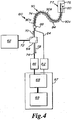
- the strain sensing system 60 may comprise an electromagnetic source 62, a coupler 64, a receiver 66, an operator console 67 operatively coupled with a microprocessor 68 and a digital storage device 69.
- the electromagnetic source 62 may generate a transmitted component 70 of electromagnetic radiation, such as a laser or a broadband light source.
- a transmission line 72 such as a fiber optic cable carries the transmitted component 70 to the coupler 64, which directs the transmitted radiation 70 through a transmitting/receiving line 74 to an optical fiber strain sensor 76.
- the transmitted component 70 may be transmitted to the optical fiber strain sensor 76 that is located within an end effector 77.
- a returned portion 78 of the transmitted radiation 70 that enters the optical fiber strain sensor 76 is returned back through the transmitting/ receiving line 74 to the receiver 66.
- the strain sensing system 60 may also comprise a temperature sensor 80 positioned proximate the optical fiber strain sensor 76 in the end effector 77.
- the temperature sensor 80 may be operatively coupled with a signal conditioner 82 via a signal cable 84.
- the signal conditioner 82 may be operatively coupled with the microprocessor 68.
- the transmitting/receiving line 74 and the signal cable 84 may be coupled through a connector 88 as depicted in FIG. 4 .
- optical fiber strain sensor 76 Although only one optical fiber strain sensor 76 is depicted, a plurality of optical fiber strain sensors and temperature sensors (not depicted) may be utilized, such as by parallel processing paths or by a multiplexing arrangement.
- the transmitting/receiving line 74 may be operatively coupled with the optical fiber strain sensor 76 through a flexible, elongate catheter assembly 90.
- the catheter assembly 90 comprises a proximal portion 90a, a middle portion 90b and a distal portion 90c.
- the distal portion 90c may include the end effector 77 containing the optical fiber strain sensor 76.
- the catheter assembly 90 may be of a hollow construction (i.e. having one or more lumens) or of a non-hollow construction (i.e. no lumen), depending on the application.
- the strain sensing system 60 may interrogate the optical fiber strain sensor 76 at an exemplary and non-limiting rate in the range of 10-Hz to 1-kHz.
- the receiver 66 manipulates and/or converts the incoming returned portion 78 into digital signals for processing by the microprocessor 68.
- the receiver 66 may be chosen from a variety of receiving devices commercially available.
- a receiver appropriate for Fabry-Perot optical fiber strain sensors is the FPI-HR signal conditioning module, produced by FISO Technologies of Quebec, QC Canada.
- a receiver appropriate for fiber Bragg grating strain sensors is the Model SM 125 Optical Sensing Interrogator, produced by Micron Optics of Atlanta, Georgia USA.
- the optical fiber strain sensor 76 is a fiber Bragg grating (FBG) and the returned portion 78 is a narrow wavelength band of radiation that is reflected from the gratings.
- the temperature sensor 80 may comprise any sensor of appropriate size and sensitivity in the temperature range of interest, such as a thermistor, resistance thermometer or thermocouple.
- a temperature compensated strain sensing assembly 100 is depicted in an embodiment of the invention that may be utilized as the end effector 77 of FIG. 4 .
- the temperature compensated strain sensing assembly 100 may have an overall diameter 102 and is depicted as being immersed in an operating environment 106.
- the temperature compensated strain sensing assembly 100 includes a deformable body 110 having an outer surface 112 and defining a central axis 114.
- the temperature compensated strain sensing assembly 100 comprises an ablation head 116 operatively coupled to the deformable body 110, and external sleeve electrodes 118a, 118b and 118c.
- An external force vector F is depicted as being applied to the ablation head 116.
- Dual coordinate systems i.e. Cartesian x-y-z and cylindrical r- ⁇ -z
- the deformable body 110 may include a collar portion 122, a neck portion 124 having a neck radius 126, a radial standoff structure 128, and an outer sleeve 130 that surrounds the neck portion 124.
- the outer sleeve 130 may bridge between the radial standoff structure 128 and the collar portion 122 and cooperate with the neck portion 124 to define an annular gap 132.
- the annular gap 132 may include a thermal insulator 134.
- An irrigation passage 140 may be defined as passing through the deformable body 110 and the ablation head 116, and may terminate at irrigation outlets 142 formed in the ablation head 116.
- An irrigation tube 144 may be operatively coupled with the irrigation passage 140 for sourcing the irrigation passage 140 with irrigation fluid 145.
- An axial gap 146 may be defined between the deformable body 110 and a base surface 148 of the ablation head 116.
- a representative wall thickness 150 is .approximately 200- to 300- micrometers; however, this wall thickness may not be representative or limiting for all embodiments.
- a plurality of optical fiber strain sensors 152 may be operatively coupled to the deformable body 110.
- One or more temperature sensors 154 may also be operatively coupled to the deformable body 110.
- the number of temperature sensors 154 is equal to the number of optical fiber strain sensors 152, one temperature sensor 154 for a corresponding optical fiber strain sensor 152, with the sensitive portion of temperature sensor 154 being mounted in close proximity to the corresponding optical fiber strain sensor 152.
- Channels 156 may be defined on the outer surface 112 of the deformable body 110 and the sensors 152, 152 coupled thereto.
- the sensitive portions of the optical fiber strain sensors 152 and temperature sensor(s) 154 may be substantially centered at the same axial location 160 relative to a proximal end 162 of the deformable body 110.
- a radially reinforced temperature compensated strain sensing assembly 180 is depicted in an embodiment of the invention.
- a helical coil 182 is arranged inside the outer sleeve 130.
- the helical coil 182 may be embedded within the outer sleeve 130.
- An annular gap 183 may be defined between the outer sleeve 130 or helical coil 182 and the deformable body 110.
- An insulation material 184 comprising a solid material may be disposed in the annular gap 183.
- the outer sleeve 130 may be comprised of thermoplastic elastomer such as polyether block amide (marketed under the trade name PEBAX, a registered trademark of the Arkema France Corp. of Colombes, France).
- the insulation material 184 may comprise a polymide or mylar sheet material rolled around the deformable body 110 within the annular gap 183.
- the helical coil 182 can provide radial stiffness while being compliant to axial and lateral forces applied on a distal portion of the end effector. Radial stiffness of the helical coil 182 can maintain the dimension of the annular gap 183 when the end effector experiences additional external pressure upon being inserted in a body or organ. By maintaining the dimension of the annular gap 183, the annular gap 183 and any insulative material that may be disposed therein substantially maintains its thermal insulative properties. Meanwhile, the compliance of the helical coil 182 to axial and bending forces enables the deformable body 118 to flex and compress without significant interference.
- the depicted embodiment also includes V-grooves 186 formed in the deformable body 110 ( FIG. 10 ) to accommodate passage of a power lead 188 and an ablation head temperature sensor 190.
- the power lead 188 and ablation head temperature sensor 190 may be routed through passageways 194 and 196, respectively in the collar portion 122 and operatively coupled to the ablation head 116.
- the passageways 194 and 196 may be filled with a suitable potting, for example, to prevent irrigation fluid 145 present in the axial gap 146 from entering the annular gap 132.
- the deformable body 110 may comprise a polymeric material such as liquid crystal polymer (LCP) or polyetheretherketone (PEEK), such as disclosed in United States Patent Application Publication Nos. 2006/0200049 and 2007/0060847 to Leo et al. , both of which are assigned to the assignee of the present application.
- LCP liquid crystal polymer
- PEEK polyetheretherketone
- the channels 156 may aid in the precise location of the sensitive portions of the sensors 152, 154.
- the optical fiber strain sensors 152 may comprise a fiber Bragg grating (FBG) sensor or a Fabry-Perot sensor.
- FBG fiber Bragg grating
- Operative coupling of the optical fiber strain sensors 152 and/or the temperature sensor(s) 154 may be accomplished in one embodiment using a glue 162.
- the glue 162 may be placed in the channels 156 or on the optical fiber strain sensors 152 and the optical fiber strain sensors 152 place in the channels 156. Excess glue may be removed after placement. Some glues may enable placement of the optical fiber strain sensors 152 in the channels 156 followed by a coating or dabbing of glue on the optical fiber strain sensors 152 to secure it to the channels 156.
- Another bonding technique may involve the use of a solvent designed to cause the material of the deformable body 110 to melt or flow while not affecting the material of the optical fiber strain sensors 152.
- the solvent may be applied to an area or zone of the deformable body 110 that encompasses at least a portion of the channels 156 where the optical fiber strain sensors 152 are to be mounted, and the optical fiber strain sensors 152 placed therein.
- the optical fiber strain sensors 152 may be temporarily held in place in the channels 156 of the deformable body 110 and the solvent applied as a coating over both. The flowing of the material in and around the channels 156 can cause a bond between the deformable body 110 and the optical fiber strain sensors 152.
- the solvent may be removed by a process such as washing or evaporation to arrest the melting process.
- the various parameters include the overall diameter 102 of approximately 2.3-mm, the irrigation passage 140 of approximately 0.4- to 0.8- mm diameter, and the representative wall thickness 150 on the order of 200- to 300- micrometers.
- the reduced neck radius 126 of the neck portion 124 and/or the decreased diameter of the irrigation passage 140 relative to configurations such as depicted in FIG. 1 provides several advantages.
- the smaller diameter irrigation passage 140 increases the Reynolds number of the fluid flow, which can increase the convection heat transfer coefficient between the irrigation fluid 145 and the boundary of the irrigation passage 140, thereby enhancing the overall heat transfer between the irrigation fluid 145 and the optical fiber strain sensors 152.
- the reduced radius 126 may also provide a reduced cross-section of material, thereby reducing the thermal conductance through the neck portion 124 in the axial direction Z and the thermal coupling between the ablation head 116 and the optical fiber strain sensors 152.
- the wall thickness 150 of the neck portion 124 can also be tailored for a desired sensitivity (displacement) of the temperature compensated strain sensing assembly 100 in response to the force vector F.
- the reduced neck radius 126 of the neck portion 124 may also provide an increased thickness of the annular gap 132 relative to existing designs, thereby enhancing the thermal isolation between the operating environment 106 and the optical fiber strain sensors 152.
- the channels 156 when present, may further decrease the thermal conduction path between the irrigation fluid 145 and the optical.fiber strain sensors 154.
- the axial gap 146 being flooded with irrigation fluid 145, may actively cool the base surface 148 of the ablation head 116 and mitigate against axial conduction of heat between the base surface 148 and the deformable body 110.
- various embodiments of the invention may cause the optical fiber strain sensors 152 to be dominated by the temperature of the irrigation fluid 145, with the influence of the ablation head 116 and the surroundings being secondary.
- An advantage of having the irrigation fluid 145 dominate the thermal state of the optical fiber strain sensors 152 is that the temperature of the irrigation fluid 145, as well as the convective coupling between the irrigation fluid 145 and the irrigation passage 140, tends to be more stable than the temperature of the ablation head 116 and the temperature and convective coupling between the operating environment 106 and the outer sleeve 130 during operation.
- the temperature sensor(s) 154 may be utilized to compensate for the thermal expansion/contraction of the optical fiber strain sensors 152 relative to the calibration or nulling state.
- the temperature profile of the neck portion 124 may be substantially uniform or at least be substantially linear with respect to the axial coordinate Z, with no substantial variation tangentially in the temperature of the deformable body 110 at a given axial location (e.g. 160).
- a single temperature sensor 154 may be sufficient to accomplish the temperature compensation, particularly if the optical fiber strain sensors 152 and the temperature sensor 154 are positioned so the sensitive portions are centered about the same axial location 160.
- Non-uniform temperatures may be produced relative to the tangential coordinate ⁇ at a given axial location Z (e.g. at axial location 160) during operation, as discussed above in reference to FIG. 3 .
- Such condition may exist, for example, where structural and / or overall size requirements do not allow for a substantially reduced neck radius 126 relative to the overall diameter 102 of the temperature compensated strain sensing assembly 100.
- Non-uniform thermal profiles may also exist due in part to uneven or non-uniform thermal contact resistances between the ablation head 116 and the deformable body 110. In such circumstances, a plurality of the temperature sensors 154 may be preferable.
- the temperature sensors 154 may number the same as the optical fiber strain sensors 152, and each of the temperature sensors 154 may be located at a position that is closer to a corresponding one of the optical fiber strain sensors 152 than any of the other optical fiber strain sensors 152. In this way, the temperature of each of the optical fiber strain sensors 152 may be more closely approximated by the measurand produce by the corresponding temperature sensor 154.
- the optical fiber strain sensors 152 may comprise a fiber Bragg grating (FBG) section of length L and having gratings etched thereon.
- the FBG section may reflect a reference wavelength ⁇ r when the FBG section is at a reference temperature Tr at a reference time r when the reference (null) measurement is performed.
- the FBG section may reflect a wavelength ⁇ t at time t relative to the reference time r.
- the wavelength ⁇ t may differ from the reference wavelength ⁇ r due to a change in the length ⁇ L of the FBG section relative to the length L at time r.
- the change in the length ⁇ L may be caused by a strain on the FBG section, a temperature change that induces a thermal expansion of the FBG section, or a combination thereof.
- the apparent strain ⁇ L/L is so named because, without knowledge of the temperature and thermal behavior of the optical fiber sensor, the ratio ⁇ L/L would appear to be the result of an elastic strain.
- the apparent strain ⁇ L/Li is equal to the elastic strains ⁇ i . Accordingly, the product ⁇ i ⁇ T i may be considered a thermal bias component of the respective apparent strain ⁇ L/L i .
- the equivalent coefficient of thermal expansion ⁇ is a parameter that is influenced by many factors.
- ⁇ is influenced primarily by the coefficient of thermal expansion (CTE) of the deformable body 110.
- the CTE of the optical fiber strain sensor 152 may also be a contributing factor, as well as the CTE of the glue 162.
- the range of the CTEs of these components can vary substantially.
- the CTE of the optical fiber strain sensor can be on the order of about 0.3 micrometers per Kelvin ( ⁇ /K), whereas the CTE of a deformable body constructed of LCP may have a CTE from 1- to 4- ⁇ /K.
- the glue 162 can have a CTE on the order of 60 ⁇ /K.
- the refractive index of the optical fiber strain sensor 152 may be sensitive to changes in temperature.
- the sensitivity of the refractive index of some optical fibers is on the order of 10 picometers per Kelvin (pm/K).
- the influence of the refractive index change may be dominant.
- the resultant changes due to refractive index changes have been known to be an order of magnitude greater than the influence of CTE changes.
- each optical fiber strain sensor 152 in a given strain sensing assembly is generally characterized by its own unique equivalent coefficient of thermal expansion ⁇ .
- Equation (4) may be expressed in matrix form.
- the products ⁇ i ⁇ T(i,t) or ⁇ i ⁇ (T(i,t)-T(i,r)) are the inferred bias components for the FBG section i.
- the inferred bias components ⁇ i ⁇ T(i,t) or ⁇ i ⁇ (T(i,t)-T(i,r)) may be determined implicitly as illustrated in Eqns. (5) and (6), or they may be determined explicitly for subtraction from the apparent strains ⁇ L/L(i,t).
- some temperature compensated strain sensing assemblies may be configured to have negligible or otherwise tolerable radial temperature gradients between optical fiber sensors, such that a single temperature sensor is adequate for the temperature correction.
- An angle of application ⁇ t of the transverse force may be computed from Table I: Table I F x,t F y,t ⁇ t ⁇ 0 ⁇ 0 arcsin(F(y,t) /F(trans,t)) ⁇ 0 ⁇ 0 ⁇ - arcsin(F(y,t)/F(trans,t) ⁇ 0 ⁇ 0 ⁇ + arcsin(F(y,t)/F(trans,t) ⁇ 0 ⁇ 0 2* ⁇ - arcsin(F(y,t) /F(trans, t)
- Equations (9) through (11) are related to the material properties of the deformable body or optical fiber strain sensors, such as the elastic moduli of the deformable body.
- Other values such as the coordinate distances between the optical fiber strain sensors, the operative lengths of the interferometric gaps and the external surface of the deformable body may be subject to variations as a consequence manufacturing tolerances.
- the digital storage device 69 may comprise a memory chip associated with the transmitting / receiving line 74 in which such information is stored, or a bar code or a RFID tag located on the body of the strain sensor assembly 20 or on the packaging.
- data specific to an individual deformable body may be uploaded to console 67 from an item of removable storage (e.g., CD, ROM or nonvolatile RAM) or via secure download from the manufacturer's website.
- the information specific to each deformable body may be obtained during a calibration step, conducted during manufacture of the deformable body, by subjecting the deformable body to a series of known force vectors.
- F(t) is the vector of forces [F(x,t), F(y,t), F(z,t)] (corresponding for example to the force vector F of FIG.
- ⁇ (t) is the vector of strains [ ⁇ 1,t , ⁇ 2,t , ⁇ 3,t ] measured by the individual optical fiber strain sensors 152
- ⁇ 0 is the vector of strains [ ⁇ 0 1 , ⁇ 0 2 , ⁇ 0 3 ] measured by the individual optical fiber strain sensors 152 with zero applied force
- K is a matrix computed when the deformable body is subjected to the series of known forces.
- the deformable body may be subjected to the following forces in series: (1) a purely axial force of known magnitude F(z,t); (2) a lateral force of known magnitude F(x,t); and (3) a lateral force of known magnitude F(y,t) applied 90 degrees to the orientation of force F(x,t).
- Force-to-strain conversion matrix K then may be stored in the digital storage device 69 associated with the corresponding deformable body, as disclosed herein.
- the values of the force-to-strain conversion matrix then may be input to console 67 when the deformable body is coupled to the console 67 using a bar code reader, input pad or direct electrical connection through transmitting / receiving line 74.
- matrix K is provided for a given deformable body, the normal force, transverse force and angle of application of the transverse force may be computed as described above and using Table I.
- the values for the normal force, transverse force and angle of application of the transverse force, computed as described above, may be output as numerical values to a display monitor that forms part of console 67.
- a graphic including a variable size or colored arrow may be displayed pointing at a position on the circumference of a circle to visualize the magnitude and direction of the transverse force applied to the distal extremity of the deformable body. By monitoring this display, the operator may continuously obtain feedback concerning the contact forces applied to the distal extremity of the deformable body.
- the invention may be practiced in other embodiments not disclosed herein, particularly where large local temperature gradients are generated in a surgical procedure.
- various aspects of the disclosed embodiments may be utilized in a cryoablation context for the treatment of prostate cancer or other urinary maladies.
- Other aspects of the disclosed embodiments may find application in endoscopic applications, such as orthroscopic surgery or entry through open orifices such as the throat, nose or anus.
- an ablation analysis 200 is presented for the radially reinforced temperature compensated strain sensing assembly 180 in an embodiment of the invention.
- the optical fiber strain sensors 152 utilized for the ablation analysis 200 were FBG optical sensors.
- the temperature sensors 154 utilized were copper-constantan (type T) thermocouples.
- the optical fiber strain sensors 152 in the radially reinforced temperature compensated strain sensing assembly 180 were uniformly spaced in the tangential coordinate ⁇ (i.e. spaced 120° apart).
- the temperature sensors 154 and the optical fiber strain sensors 152 were substantially centered at the same axial location on the deformable body 110, such as depicted in FIG. 9 .
- Each of the temperature sensors 154 were located closer to a corresponding one of the optical fiber strain sensors 152 than to the other optical fiber strain sensors 154 (e.g. FIG. 12 ), and thus represented the temperature of the corresponding closest optical fiber strain sensor 154.
- the ablation analysis 200 comprises a temperature variation graph 202, a wavelength variation graph 204 and a resolved force component graph 206, all obtained simultaneously with the radially reinforced temperature compensated strain sensing assembly 180 residing in a beating heart during an ablation operation.
- the three graphs 202, 204 and 206 share a common time abscissa 210 that spans about 80 seconds.
- the temperature variation graph 202 presents a temperature variation ordinate 212 in degrees Celsius for indication of the variation in indicated temperatures 214, 216 and 218 of the three temperature sensors 154.
- the wavelength variation graph 204 presents a wavelength variation ordinate 222 in nanometers for indication of central wavelength variation in the reflected signals 224, 226 and 228 from each of the trio of FBG optical sensors.
- the resolved force component graph 206 presents a force variation ordinate 232 for indication of the variation in a resolved axial force component 234 and a resolved transverse force component 236.
- the corrected reflected signals 224, 226, 228 and resolved forces 234, 236 were compensated according to the method described in Eqns. (1) through (6) and Eqns. (9) through (14).
- the procedure followed for generating the ablation analysis 200 was to obtain null measurements for the various ordinates 212, 222 and 232 with the radially reinforced temperature compensated strain sensing assembly 180 at substantial thermal equilibrium with its surroundings and with an irrigation flow (e.g. irrigation flow 145 of FIG. 7 ) of 2 cubic centimeters per minute (ccm).
- the irrigation flow rate was increased to 17 ccm at an increased irrigation onset time 240 and maintained for an increased cooling time interval 242, after which the irrigation flow was returned to 2 ccm.
- the effect of the increased cooling time interval was to produce an interval of reduced temperature 244.
- the ablation head 116 was energized continuously over an ablation operation time interval 246, starting at an ablation onset time 248.
- the temperature variation graph 202 indicates a temperature drop 252 during the increased cooling interval 242, caused by a dominant cooling effect of the increased flow rate in the irrigation fluid.
- the indicated temperatures 214, 216 and 218 remains substantially stable for the duration of the ablation time interval 246.
- the indicated temperatures 214, 216 and 218 returned to substantially the same level as the null measurement.
- the wavelength variation graph 204 indicates a shift 254 in the time-averaged wavelength variations 222 of the reflected signals 224, 226, 228 during the interval of reduced temperature 244.
- the magnitude of the shift 254 is about 0.08-nm, which translates to an elastic force of about 80-gm for the particular strain sensing assembly under test.
- the resolved forces 234, 236, which are compensated for temperature change maintain essentially a steady time averaged level. That is, while these signals oscillate about respective mean values due to the pulsing nature of the application, the mean values themselves remain essentially steady, regardless of the changes in the indicated temperatures 214, 216 and 218 and reflected signals 224, 226, 228.
- the above disclosed apparatus and method effectively compensates for thermal induced changes in the optical fiber strain sensors 152.
- a temperature depression 258 is observed for the three indicated temperatures 214, 216, 218.
- the temperature depression 258 drops approximately 0.5 °C from the temperature levels established during the ablation operation time interval 246 to a substantially steady state level.
- the temperature depression 258 is believed to be the result of reduced heat transfer, both radially and axially, through the radially enforced temperature compensated force sensor 180. Accordingly, the difference between the temperature during the ablation operation time interval 246 and the steady-state extremity of the temperature depression 258 for one of the indicated temperatures 214, 216, 218 illustrates the effect of the ablation operation.
- the small decrease of the temperature depression 258 relative to the temperature drop 252 implies that the temperature sensors 154 and the optical fiber strain sensors 152 are dominated by the flow of the irrigation fluid 145, and that the effects of ablation are secondary when the radially enforced temperature compensated force sensor 180 is being actively cooled by the irrigation fluid 145.
- FIGS. 14 and 15 a method of calibrating or verifying the calibration of a temperature compensated strain sensing assembly of the present invention is described in an embodiment of the invention.
- Figure 14 depicts a calibration data plot 270 of the temperature variation graph 206 and the wavelength variation graph 208, with the indicated temperatures 214, 216 and 218 are slowly oscillating with a time period 274 of approximately 6 seconds.
- the reflected signals 224, 226 and 228 also oscillate, closely tracking the indicated temperatures 214, 216 and 218.
- the amplitude of the temperature oscillation is just under 1° C.
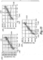
- Figure 15 depicts a trio of correlation plots 280, 282 and 284.
- Each of the correlation plots 280, 282, 284 includes a reflected central wavelength ordinate 288 in nanometers and a temperature abscissa 290 in degrees Celsius.
- Each of the correlation plots 280, 282, 284 includes correlation data 281, 283 and 285 from one of the reflected signals 224, 226, 228 and a corresponding one of the indicated temperatures 214, 216, 218.
- correlation plot 280 presents correlation data 281 of the wavelengths of the reflected signal 224 plotted against the indicated temperature 214
- correlation plot 282 presents correlation data 283 of the wavelengths of the reflected signal 226 plotted against the indicated temperature 216
- correlation plot 284 presents correlation data 285 the wavelengths of the reflected signal 228 plotted against the indicated temperature 218.
- Each of the correlation plots 280, 282 and 284 also presents a line fit 294, 296 and 298 of the respective temperature/wavelength data.
- the line fit may be acquired using least-squares fitting techniques.
- the slope of the line fits 294, 296, 298 provides a calibration of the change in the central reflected wavelengths, which can then be utilized to provide the equivalent coefficients of thermal expansion ⁇ 1, ⁇ 2 and ⁇ 3 ofEqn. (6).
- the oscillating temperatures may be produced a variety of ways.
- the oscillation was produced by immersing the radially reinforced temperature compensated strain sensing assembly 180 in a warm bath at a temperature of about 36° C without the tip being in contact or otherwise experiencing an external force. Irrigation fluid at about 31° C was then pumped through the strain sensing assembly 180 at a low flow rate (about 2 ccm) with a peristaltic pump. Peristaltic pumps produce an oscillatory flow which, if slow enough (long enough period) can cause an oscillatory cooling of the optical fiber strain sensors 152 of the strain sensing assembly 180. As the flow waxes and wanes through the strain sensing assembly 180, data for the calibration can be gathered and the correlations drawn.
- the technique of this embodiment may be implemented as a stand alone calibration or as an in-situ calibration or calibration check.
- the difference between the hot and cold temperatures of the bath and irrigation fluid, respectively may represent a large temperature range, so that the curve fit is over a temperature range representative of what is experienced in a high energy dissipation application such as ablation.
- the line fit in such a scenario may be utilized to account for non-linearities in the calibration, such as by fitting the data to a higher order polynomial.
- a line fit over a more narrow range of temperatures may be utilized.
- the data may be used to generate a calibration or to check the validity of a prior calibration.
Landscapes
- Health & Medical Sciences (AREA)
- Life Sciences & Earth Sciences (AREA)
- Surgery (AREA)
- Engineering & Computer Science (AREA)
- General Health & Medical Sciences (AREA)
- Veterinary Medicine (AREA)
- Biomedical Technology (AREA)
- Heart & Thoracic Surgery (AREA)
- Medical Informatics (AREA)
- Molecular Biology (AREA)
- Public Health (AREA)
- Animal Behavior & Ethology (AREA)
- Pathology (AREA)
- Biophysics (AREA)
- Physics & Mathematics (AREA)
- Nuclear Medicine, Radiotherapy & Molecular Imaging (AREA)
- Oral & Maxillofacial Surgery (AREA)
- Length Measuring Devices By Optical Means (AREA)
- Optical Transform (AREA)
- Surgical Instruments (AREA)
- Media Introduction/Drainage Providing Device (AREA)
Claims (10)
- Cathéter à utiliser dans une procédure médicale pourvu d'un système de détection de contraintes, comprenant :un corps allongé flexible (90) adapté pour être introduit dans un patient durant ladite procédure médicale et incluant un effecteur terminal (77), ledit effecteur terminal incluant un ensemble de détection de contraintes (100), ledit ensemble de détection de contraintes étant caractérisé par :un corps déformable (110) ;une pluralité de capteurs de contraintes à fibres optiques (152) fonctionnellement couplés audit corps déformable ;un nombre égal de capteurs de température (154), respectivement à proximité de ladite pluralité de capteurs de contraintes à fibres optiques afin de déterminer les températures respectives de ladite pluralité de capteurs de contraintes à fibres, ladite pluralité de capteurs de contraintes à fibres optiques (152) et ladite pluralité de capteurs de température étant centrés au niveau du même emplacement axial (160) par rapport à une extrémité proximale (162) du corps déformable (110) et chacun des capteurs de température (154) étant espacé en rotation de manière équidistante les uns des autres,et des canaux (156) définis sur une surface extérieure (112) du corps déformable (110) pour faciliter la localisation précise de parties sensibles des capteurs de contraintes à fibres optiques (152) et des capteurs de température (154), respectivement, en plaçant les capteurs (152, 154) dans les canaux (156).
- Cathéter selon la revendication 1 dans lequel chaque capteur de ladite pluralité de capteurs de température est positionné sensiblement plus près d'un capteur correspondant de ladite pluralité de capteurs de contraintes à fibres optiques que des autres capteurs de ladite pluralité de capteurs de contraintes à fibres optiques.
- Cathéter selon la revendication 1 ou 2, dans lequel lesdits capteurs de contraintes à fibres optiques sont des capteurs de réseau de Bragg à fibres.
- Cathéter selon l'une quelconque des revendications 1-3, dans lequel lesdits capteurs de température sont des thermocouples.
- Cathéter selon l'une quelconque des revendications 1-4, dans lequel ledit corps déformable comprend un matériau polymère à cristaux liquides.
- Cathéter selon l'une quelconque des revendications 1-5,
dans lequel ladite pluralité de capteurs de contraintes à fibres optiques sont au nombre de trois et ladite pluralité de capteurs de température sont au nombre de trois. - Cathéter selon l'une quelconque des revendications 1-6, comprenant en outre :une source électromagnétique (62) fonctionnement couplée à ladite pluralité de capteurs de contraintes à fibres optiques pour transmission de rayonnement électromagnétique (70) à ladite pluralité de capteurs de contraintes à fibres optiques ;au moins un récepteur (66) fonctionnement couplé à ladite pluralité de capteurs de contraintes à fibres optiques pour réception d'une partie retournée (78) dudit rayonnement électromagnétique, ladite partie retournée étant retournée par ladite pluralité de capteurs de contraintes à fibres optiques ;au moins un conditionneur de signal (82) fonctionnellement couplé à ladite pluralité de capteurs de température pour mesure de températures à proximité de ladite pluralité de capteurs de contraintes à fibres optiques ; etun microprocesseur (68) fonctionnellement couplé audit récepteur et audit conditionneur de signal.
- Cathéter selon la revendication 7, comprenant en outre un dispositif de stockage numérique (69) fonctionnellement couplé audit microprocesseur, ledit dispositif de stockage numérique incluant des instructions pour exécution par ledit microprocesseur, lesdites instructions incluant :la détermination d'une pluralité de contraintes apparentes, une pour chaque capteur de ladite pluralité de capteurs de contraintes à fibres optiques, ladite pluralité de contraintes apparentes étant déduites de ladite partie retournée de rayonnement électromagnétique ;la détermination d'une pluralité de composantes de sollicitation thermique, une pour chaque capteur de ladite pluralité de contraintes apparentes, ladite pluralité de composantes de sollicitation thermique étant déduites desdites températures à proximité de ladite pluralité de capteurs de contraintes à fibres optiques ;la déduction d'une contrainte élastique pour chaque capteur de ladite pluralité de capteurs à fibres optiques sur la base de laditecontrainte apparente et de ladite composante de sollicitation thermique de chaque capteur de ladite pluralité de capteurs à fibres optiques ; etla détermination d'une amplitude et d'une direction d'une force exercée sur ladite extrémité distale dudit cathéter à partir de ladite pluralité de contraintes élastiques.
- Cathéter selon la revendication 7 ou 8, dans lequel ladite source électromagnétique est un laser.
- Cathéter selon la revendication 7, 8 ou 9,
dans lequel chaque capteur de ladite pluralité de capteurs de température est un thermocouple.
Applications Claiming Priority (2)
| Application Number | Priority Date | Filing Date | Title |
|---|---|---|---|
| US12/152,473 US8298227B2 (en) | 2008-05-14 | 2008-05-14 | Temperature compensated strain sensing catheter |
| PCT/IB2009/051967 WO2009138957A2 (fr) | 2008-05-14 | 2009-05-13 | Cathéter de détection des contraintes à compensation thermique |
Publications (2)
| Publication Number | Publication Date |
|---|---|
| EP2291135A2 EP2291135A2 (fr) | 2011-03-09 |
| EP2291135B1 true EP2291135B1 (fr) | 2016-12-21 |
Family
ID=41168520
Family Applications (1)
| Application Number | Title | Priority Date | Filing Date |
|---|---|---|---|
| EP09746251.9A Active EP2291135B1 (fr) | 2008-05-14 | 2009-05-13 | Cathéter de détection des contraintes à compensation thermique |
Country Status (5)
| Country | Link |
|---|---|
| US (1) | US8298227B2 (fr) |
| EP (1) | EP2291135B1 (fr) |
| JP (1) | JP5572155B2 (fr) |
| CN (1) | CN102098974B (fr) |
| WO (1) | WO2009138957A2 (fr) |
Families Citing this family (82)
| Publication number | Priority date | Publication date | Assignee | Title |
|---|---|---|---|---|
| US8182433B2 (en) | 2005-03-04 | 2012-05-22 | Endosense Sa | Medical apparatus system having optical fiber load sensing capability |
| US8075498B2 (en) | 2005-03-04 | 2011-12-13 | Endosense Sa | Medical apparatus system having optical fiber load sensing capability |
| US8894589B2 (en) | 2005-08-01 | 2014-11-25 | Endosense Sa | Medical apparatus system having optical fiber load sensing capability |
| US8567265B2 (en) | 2006-06-09 | 2013-10-29 | Endosense, SA | Triaxial fiber optic force sensing catheter |
| US8048063B2 (en) | 2006-06-09 | 2011-11-01 | Endosense Sa | Catheter having tri-axial force sensor |
| US8622935B1 (en) | 2007-05-25 | 2014-01-07 | Endosense Sa | Elongated surgical manipulator with body position and distal force sensing |
| JP4977810B1 (ja) * | 2009-04-22 | 2012-07-18 | ホッティンガー バルトヴィン メッセテヒニーク ゲーエムベーハー | ファイバブラッググレーティングを備えた光学歪み測定装置 |
| US8649847B1 (en) * | 2009-05-04 | 2014-02-11 | Intelligent Fiber Optic Systems, Inc. | Steerable shape sensing biopsy needle and catheter |
| US9226791B2 (en) | 2012-03-12 | 2016-01-05 | Advanced Cardiac Therapeutics, Inc. | Systems for temperature-controlled ablation using radiometric feedback |
| US8954161B2 (en) | 2012-06-01 | 2015-02-10 | Advanced Cardiac Therapeutics, Inc. | Systems and methods for radiometrically measuring temperature and detecting tissue contact prior to and during tissue ablation |
| US8926605B2 (en) | 2012-02-07 | 2015-01-06 | Advanced Cardiac Therapeutics, Inc. | Systems and methods for radiometrically measuring temperature during tissue ablation |
| US9277961B2 (en) | 2009-06-12 | 2016-03-08 | Advanced Cardiac Therapeutics, Inc. | Systems and methods of radiometrically determining a hot-spot temperature of tissue being treated |
| WO2011053766A1 (fr) * | 2009-10-30 | 2011-05-05 | Advanced Bionics, Llc | Stylet orientable |
| US8906013B2 (en) | 2010-04-09 | 2014-12-09 | Endosense Sa | Control handle for a contact force ablation catheter |
| US9179968B2 (en) | 2010-05-10 | 2015-11-10 | St. Jude Medical Luxembourg Holding S.À.R.L. | Irrigated finned ablation head |
| US10448837B2 (en) | 2010-08-23 | 2019-10-22 | Knonklijke Philips N.V. | Mapping system and method for medical procedures |
| BR112013018983A2 (pt) * | 2011-01-27 | 2017-11-07 | Koninl Philips Electronics Nv | instrumento médico, sistema para calibração de um instrumento médico e método |
| US20120220879A1 (en) * | 2011-02-24 | 2012-08-30 | Vascomed Gmbh | Catheter and Catheter Arrangement |
| CN103607961B (zh) * | 2011-04-14 | 2016-12-14 | 圣犹达医疗用品卢森堡控股有限公司 | 用于导管的紧凑型力传感器 |
| SG194782A1 (en) | 2011-05-04 | 2013-12-30 | Agency Science Tech & Res | Fiber bragg grating (fbg) sensor |
| WO2013030749A2 (fr) * | 2011-09-02 | 2013-03-07 | Koninklijke Philips Electronics N.V. | Informations d'insertion et de sortie de dispositif médical au moyen d'une détection répartie de température à fibre optique |
| ES2727868T3 (es) | 2011-09-22 | 2019-10-21 | Univ George Washington | Sistemas para visualizar el tejido ablacionado |
| CN104066368B (zh) | 2011-09-22 | 2017-02-22 | 乔治华盛顿大学 | 用于使经消融组织可视化的系统和方法 |
| US20130131500A1 (en) * | 2011-11-18 | 2013-05-23 | Covidien Lp | In-situ proximity recognition apparatus |
| ES2556810T3 (es) * | 2012-02-07 | 2016-01-20 | Sensoptic Sa | Elemento óptico sensor de fuerza e instrumento microquirúrgico |
| US9289263B2 (en) | 2012-03-23 | 2016-03-22 | Vascomed Gmbh | Catheter arrangement |
| EP2830482A1 (fr) * | 2012-03-29 | 2015-02-04 | Koninklijke Philips N.V. | Mécanismes de régulation de température pour une détection de forme stable |
| US10022190B2 (en) * | 2012-04-04 | 2018-07-17 | Universite Libre De Bruxelles | Optical force transducer |
| US9023039B2 (en) * | 2012-07-19 | 2015-05-05 | Covidien Lp | Electrosurgical device including an optical sensor |
| US9113904B2 (en) | 2012-07-19 | 2015-08-25 | Covidien Lp | Surgical instrument with fiber bragg grating |
| EP2711676B1 (fr) | 2012-09-20 | 2020-10-07 | VascoMed GmbH | Capteur de force à fibre optique, dispositif de mesure de force et cathéter |
| CN103148894A (zh) * | 2013-02-04 | 2013-06-12 | 中国科学院半导体研究所 | 基于光纤布拉格光栅的角度应力传感器 |
| US9174024B1 (en) | 2013-03-15 | 2015-11-03 | St. Jude Medical Luxembourg Holdings S.À.R.L. | Steering control mechanisms for catheters |
| US9095682B2 (en) | 2013-04-30 | 2015-08-04 | St. Jude Medical Luxembourg Holding S.À.R.L. | Control handles for catheters |
| WO2014186908A1 (fr) * | 2013-05-24 | 2014-11-27 | Ehsan Toyserkani | Capteur optique multi parametre et procede de fabrication de capteur optique |
| US10987155B2 (en) * | 2013-06-28 | 2021-04-27 | Orbsurgical Ltd. | Bipolar forceps with force measurement |
| EP2851028A1 (fr) | 2013-08-15 | 2015-03-25 | VascoMed GmbH | Système de cathéter et procédé de détermination d'une force agissant sur une extrémité de cathéter |
| CN103575331B (zh) * | 2013-10-16 | 2016-08-17 | 哈尔滨工业大学 | 一种高温结构温度和应变的同时测试方法 |
| EP2865326A1 (fr) * | 2013-10-25 | 2015-04-29 | Sinvent AS | Système de surveillance de la pression in vivo |
| JP6737705B2 (ja) | 2013-11-14 | 2020-08-12 | ザ・ジョージ・ワシントン・ユニバーシティThe George Washingtonuniversity | 損傷部位の深さを決定するシステムの動作方法及び心臓組織の画像を生成するシステム |
| US20150141847A1 (en) | 2013-11-20 | 2015-05-21 | The George Washington University | Systems and methods for hyperspectral analysis of cardiac tissue |
| WO2015092590A1 (fr) * | 2013-12-17 | 2015-06-25 | Koninklijke Philips N.V. | Système et procédé pour déterminer le point d'entrée sur le corps à l'aide d'une détection de forme optique |
| GB2522472B (en) * | 2014-01-27 | 2017-09-06 | Epsilon Optics Aerospace Ltd | A method and apparatus for a structural monitoring device adapted to be locatable within a tubular structure |
| US10835313B2 (en) * | 2014-01-30 | 2020-11-17 | Medlumics S.L. | Radiofrequency ablation catheter with optical tissue evaluation |
| US10322299B2 (en) * | 2014-02-27 | 2019-06-18 | Koninklijke Philips N.V. | System for performing a therapeutic procedure |
| BR102014023265B1 (pt) * | 2014-09-19 | 2021-05-04 | Technip France | método de calibração para uma tubulação flexível |
| JP6771731B2 (ja) | 2014-11-03 | 2020-10-21 | 460メディカル・インコーポレイテッド460Medical, Inc. | 接触性評価システム及び方法 |
| EP3215002B1 (fr) | 2014-11-03 | 2024-03-20 | The George Washington University | Systèmes d'évaluation de lésion |
| EP3220844B1 (fr) | 2014-11-19 | 2020-11-11 | EPiX Therapeutics, Inc. | Systèmes de cartographie à haute résolution de tissu |
| WO2016081611A1 (fr) | 2014-11-19 | 2016-05-26 | Advanced Cardiac Therapeutics, Inc. | Cartographie haute résolution de tissus avec stimulation cardiaque |
| WO2016081650A1 (fr) | 2014-11-19 | 2016-05-26 | Advanced Cardiac Therapeutics, Inc. | Dispositifs d'ablation, systèmes et procédés d'utilisation d'ensemble électrode à haute résolution |
| US9810594B2 (en) | 2015-01-08 | 2017-11-07 | Kulite Semiconductor Products, Inc. | Thermally stable high temperature pressure and acceleration optical interferometric sensors |
| US9952067B2 (en) | 2015-05-06 | 2018-04-24 | Kulite Semiconductor Products, Inc. | Systems and methods for optical measurements using multiple beam interferometric sensors |
| CA2980620A1 (fr) | 2015-03-23 | 2016-09-29 | Farrokh JANABI-SHARIFI | Ensembles capteurs de force et de couple insensibles aux variations de temperature |
| US9636164B2 (en) | 2015-03-25 | 2017-05-02 | Advanced Cardiac Therapeutics, Inc. | Contact sensing systems and methods |
| CN106264708A (zh) * | 2015-05-27 | 2017-01-04 | 乐普(北京)医疗器械股份有限公司 | 一种压力导管受力检测装置 |
| CN106175922A (zh) * | 2015-05-27 | 2016-12-07 | 乐普(北京)医疗器械股份有限公司 | 一种测量压力导管受力的方法 |
| US10317196B2 (en) * | 2015-06-17 | 2019-06-11 | The Charles Stark Draper Laboratory, Inc. | Navigation systems and methods using fiber optic shape sensors and localized position sensors |
| CN106308921A (zh) * | 2015-06-30 | 2017-01-11 | 四川锦江电子科技有限公司 | 一种具有压力检测的消融装置 |
| US10779904B2 (en) | 2015-07-19 | 2020-09-22 | 460Medical, Inc. | Systems and methods for lesion formation and assessment |
| JP6691602B2 (ja) | 2016-01-07 | 2020-04-28 | セント・ジュード・メディカル・インターナショナル・ホールディング・エスエーアールエルSt. Jude Medical International Holding S.a,r.l. | 光学的感知のためのマルチ・コア・ファイバを有する医療デバイス |
| WO2017136548A1 (fr) | 2016-02-04 | 2017-08-10 | Cardiac Pacemakers, Inc. | Système de pose avec capteur de force pour dispositif cardiaque sans fil |
| SG11201807618QA (en) | 2016-03-15 | 2018-10-30 | Epix Therapeutics Inc | Improved devices, systems and methods for irrigated ablation |
| CN106706160A (zh) * | 2016-12-29 | 2017-05-24 | 电子科技大学 | 一种基于光纤珐珀传感器的温度补偿系统及方法 |
| EP3614946B1 (fr) | 2017-04-27 | 2024-03-20 | EPiX Therapeutics, Inc. | Détermination de la nature d'un contact entre une pointe de cathéter et un tissu |
| CN108577977B (zh) * | 2018-03-19 | 2020-10-30 | 山东大学 | 穿刺针及穿刺针运动轨迹的三维重建方法及系统 |
| WO2019226119A1 (fr) | 2018-05-22 | 2019-11-28 | Nanyang Technological University | Capteur de force pour mécanismes actionnés par un tendon |
| US12144539B2 (en) | 2018-05-30 | 2024-11-19 | Avent, Inc. | Varying the length of a temperature sensing element of a radiofrequency probe based on desired lesion size |
| ES3056750T3 (en) | 2018-05-30 | 2026-02-24 | Avent Inc | System for generating lesions of a certain size by controlling energy delivered and pump flow rate |
| ES3015689T3 (en) | 2018-05-30 | 2025-05-07 | Avent Inc | Medical probe assembly for mitigating rising impedance via a pump assembly during use of cooled radiofrequency probes |
| WO2020144159A1 (fr) * | 2019-01-07 | 2020-07-16 | Koninklijke Philips N.V. | Soulagement de traction pour imagerie ultrasonore intraluminale et dispostifs, systèmes et procédés associés |
| US11975157B2 (en) | 2019-04-12 | 2024-05-07 | Covidien Lp | Method of manufacturing an elongated catheter having multiple sensors for three-dimensional location of the catheter |
| US11452563B2 (en) | 2019-05-06 | 2022-09-27 | Biosense Webster (Israel) Ltd. | Adapting irrigation rate in radiofrequency (RF) ablation in response to contact-force variation |
| CN114040722B (zh) * | 2019-08-29 | 2025-01-28 | 圣犹达医疗用品心脏病学部门有限公司 | 包括密封电极尖端组件的力传感导管及其组装方法 |
| US12076081B2 (en) | 2020-01-08 | 2024-09-03 | 460Medical, Inc. | Systems and methods for optical interrogation of ablation lesions |
| US12303290B2 (en) | 2020-01-27 | 2025-05-20 | Howmedica Osteonics Corp. | Medical sensor and method |
| WO2021243061A1 (fr) | 2020-05-27 | 2021-12-02 | The George Washington University | Visualisation de lésions par une approche à deux longueurs d'onde |
| US11883326B2 (en) | 2020-11-03 | 2024-01-30 | Johnson & Johnson Surgical Vision, Inc. | Phacoemulsification probe stroke length maximization system |
| US12558150B2 (en) * | 2021-10-19 | 2026-02-24 | Verb Surgical Inc. | Integrated sensors for energy tools |
| WO2023192371A1 (fr) * | 2022-04-01 | 2023-10-05 | Baker Hughes Oilfield Operations Llc | Procédé de conditionnement d'une fibre optique pour mesure simultanée de température et de déformation facilitant la gestion des actifs industriels |
| CN119714185B (zh) * | 2024-12-27 | 2025-09-23 | 广西交科集团有限公司 | 一种旧板桥应变实时监测数据的异常实时诊断方法及系统 |
| CN120114728B (zh) * | 2025-04-14 | 2026-02-13 | 艾科脉医疗器械(绍兴)有限公司 | 一种压力感知的电生理导管 |
Family Cites Families (141)
| Publication number | Priority date | Publication date | Assignee | Title |
|---|---|---|---|---|
| DE3020785A1 (de) | 1980-05-31 | 1981-12-10 | Erich 7993 Kressbronn Brosa | Messwandler |
| US5696863A (en) | 1982-08-06 | 1997-12-09 | Kleinerman; Marcos Y. | Distributed fiber optic temperature sensors and systems |
| US5178153A (en) * | 1984-03-08 | 1993-01-12 | Einzig Robert E | Fluid flow sensing apparatus for in vivo and industrial applications employing novel differential optical fiber pressure sensors |
| US4873989A (en) | 1984-03-08 | 1989-10-17 | Optical Technologies, Inc. | Fluid flow sensing apparatus for in vivo and industrial applications employing novel optical fiber pressure sensors |
| US5693043A (en) | 1985-03-22 | 1997-12-02 | Massachusetts Institute Of Technology | Catheter for laser angiosurgery |
| US5104392A (en) * | 1985-03-22 | 1992-04-14 | Massachusetts Institute Of Technology | Laser spectro-optic imaging for diagnosis and treatment of diseased tissue |
| EP0214712B1 (fr) * | 1985-07-31 | 1992-09-02 | C.R. Bard, Inc. | Dispositif de cathéter à laser infrarouge |
| SE453561B (sv) * | 1986-06-25 | 1988-02-15 | Radisensor Ab | Miniatyriserad sensor for fysiologiska tryckmetningar |
| US4757194A (en) * | 1986-10-10 | 1988-07-12 | Oxbridge, Inc. | Methods and apparatus for sensing the mechanical application of force |
| US4796622A (en) | 1987-03-06 | 1989-01-10 | The United States Of America As Represented By The Department Of Health And Human Services | Catheter with oxyhydrogen catalytic thermal tip |
| FR2613065B1 (fr) * | 1987-03-24 | 1991-07-26 | Electricite De France | Interferometre de michelson a fibres optiques et son application notamment a la mesure des temperatures |
| US4983034A (en) * | 1987-12-10 | 1991-01-08 | Simmonds Precision Products, Inc. | Composite integrity monitoring |
| US5201317A (en) * | 1988-06-06 | 1993-04-13 | Sumitomo Electric Industries, Ltd. | Diagnostic and therapeutic catheter |
| DE3828550A1 (de) | 1988-08-23 | 1990-03-01 | Rheinmetall Gmbh | Kraftmessring |
| US6066130A (en) * | 1988-10-24 | 2000-05-23 | The General Hospital Corporation | Delivering laser energy |
| US4966597A (en) | 1988-11-04 | 1990-10-30 | Cosman Eric R | Thermometric cardiac tissue ablation electrode with ultra-sensitive temperature detection |
| US5014709A (en) * | 1989-06-13 | 1991-05-14 | Biologic Systems Corp. | Method and apparatus for high resolution holographic imaging of biological tissue |
| CA2044159C (fr) * | 1989-10-11 | 2003-04-15 | John P. Hall | Moniteur de la pression intracranienne integrale et catheter de drainage |
| US5321510A (en) * | 1989-11-13 | 1994-06-14 | Texas Instruments Incorporated | Serial video processor |
| US5122137A (en) | 1990-04-27 | 1992-06-16 | Boston Scientific Corporation | Temperature controlled rf coagulation |
| US5065010A (en) | 1990-08-30 | 1991-11-12 | Camino Laboratories | Fiber optic measurement system having a reference conductor for controlling the energy level of the light source |
| US5321501A (en) * | 1991-04-29 | 1994-06-14 | Massachusetts Institute Of Technology | Method and apparatus for optical imaging with means for controlling the longitudinal range of the sample |
| US6134003A (en) | 1991-04-29 | 2000-10-17 | Massachusetts Institute Of Technology | Method and apparatus for performing optical measurements using a fiber optic imaging guidewire, catheter or endoscope |
| US5633494A (en) * | 1991-07-31 | 1997-05-27 | Danisch; Lee | Fiber optic bending and positioning sensor with selected curved light emission surfaces |
| US5645065A (en) | 1991-09-04 | 1997-07-08 | Navion Biomedical Corporation | Catheter depth, position and orientation location system |
| US5906614A (en) * | 1991-11-08 | 1999-05-25 | Ep Technologies, Inc. | Tissue heating and ablation systems and methods using predicted temperature for monitoring and control |
| JPH05212118A (ja) * | 1992-02-06 | 1993-08-24 | Inter Noba Kk | ホットバルーンカテーテルとこのホットバルーンカテーテルを用いた血管拡張方法 |
| DE4204521C1 (fr) * | 1992-02-15 | 1993-06-24 | Daimler-Benz Aktiengesellschaft, 7000 Stuttgart, De | |
| US5423807A (en) * | 1992-04-16 | 1995-06-13 | Implemed, Inc. | Cryogenic mapping and ablation catheter |
| US5772590A (en) * | 1992-06-30 | 1998-06-30 | Cordis Webster, Inc. | Cardiovascular catheter with laterally stable basket-shaped electrode array with puller wire |
| US5202939A (en) * | 1992-07-21 | 1993-04-13 | Institut National D'optique | Fabry-perot optical sensing device for measuring a physical parameter |
| US5279793A (en) * | 1992-09-01 | 1994-01-18 | Glass Alexander J | Optical osmometer for chemical detection |
| US5348019A (en) * | 1992-09-18 | 1994-09-20 | The Board Of Regents Of The University Of Oklahoma | Optical fiber pressure sensing catheter |
| US5662108A (en) | 1992-09-23 | 1997-09-02 | Endocardial Solutions, Inc. | Electrophysiology mapping system |
| US5706809A (en) | 1993-01-29 | 1998-01-13 | Cardima, Inc. | Method and system for using multiple intravascular sensing devices to detect electrical activity |
| US5446546A (en) * | 1993-07-02 | 1995-08-29 | The Boeing Company | Laser interferometric single piece force transducer |
| US5409000A (en) * | 1993-09-14 | 1995-04-25 | Cardiac Pathways Corporation | Endocardial mapping and ablation system utilizing separately controlled steerable ablation catheter with ultrasonic imaging capabilities and method |
| US5464404A (en) | 1993-09-20 | 1995-11-07 | Abela Laser Systems, Inc. | Cardiac ablation catheters and method |
| US5396887A (en) * | 1993-09-23 | 1995-03-14 | Cardiac Pathways Corporation | Apparatus and method for detecting contact pressure |
| CA2194062C (fr) * | 1994-06-27 | 2005-06-28 | Dorin Panescu | Systeme de regulation de l'ablation de tissus utilisant des capteurs de temperature |
| NO302441B1 (no) | 1995-03-20 | 1998-03-02 | Optoplan As | Fiberoptisk endepumpet fiber-laser |
| US6246898B1 (en) | 1995-03-28 | 2001-06-12 | Sonometrics Corporation | Method for carrying out a medical procedure using a three-dimensional tracking and imaging system |
| US5688267A (en) | 1995-05-01 | 1997-11-18 | Ep Technologies, Inc. | Systems and methods for sensing multiple temperature conditions during tissue ablation |
| US5594819A (en) * | 1995-07-26 | 1997-01-14 | Electric Power Research Institute | Field-mountable fiber optic sensors for long term strain monitoring in hostile environments |
| US6309580B1 (en) | 1995-11-15 | 2001-10-30 | Regents Of The University Of Minnesota | Release surfaces, particularly for use in nanoimprint lithography |
| JP3737554B2 (ja) * | 1996-01-09 | 2006-01-18 | 株式会社東海理化電機製作所 | センサ機能を備えたカテーテル |
| US5697380A (en) * | 1996-01-11 | 1997-12-16 | Intella Interventional Systems, Inc. | Guide wire having distal extremity with adjustable support characteristic and method |
| WO1997029678A2 (fr) | 1996-02-15 | 1997-08-21 | Biosense Inc. | Systeme de controle de l'etalonnage et de l'utilisation d'un catheter |
| US5798521A (en) * | 1996-02-27 | 1998-08-25 | The United States Of America As Represented By The Administrator Of The National Aeronautics And Space Administration | Apparatus and method for measuring strain in bragg gratings |
| WO1998008073A1 (fr) * | 1996-08-23 | 1998-02-26 | Osteobiologics, Inc. | Dispositif d'essai de materiaux tenu a la main |
| US6719755B2 (en) * | 1996-10-22 | 2004-04-13 | Epicor Medical, Inc. | Methods and devices for ablation |
| US6102926A (en) * | 1996-12-02 | 2000-08-15 | Angiotrax, Inc. | Apparatus for percutaneously performing myocardial revascularization having means for sensing tissue parameters and methods of use |
| US6120520A (en) * | 1997-05-27 | 2000-09-19 | Angiotrax, Inc. | Apparatus and methods for stimulating revascularization and/or tissue growth |
| US5782828A (en) * | 1996-12-11 | 1998-07-21 | Irvine Biomedical, Inc. | Ablation catheter with multiple flexible curves |
| EP1491139B1 (fr) * | 1997-01-03 | 2007-08-29 | Biosense Webster, Inc. | Cathéter sensible à une courbure |
| US5859717A (en) * | 1997-02-14 | 1999-01-12 | Corning Oca Corporation | Multiplexing device with precision optical block |
| US6056436A (en) * | 1997-02-20 | 2000-05-02 | University Of Maryland | Simultaneous measurement of temperature and strain using optical sensors |
| US5833688A (en) | 1997-02-24 | 1998-11-10 | Boston Scientific Corporation | Sensing temperature with plurality of catheter sensors |
| US6063078A (en) * | 1997-03-12 | 2000-05-16 | Medtronic, Inc. | Method and apparatus for tissue ablation |
| DE19721362B4 (de) * | 1997-04-01 | 2011-05-26 | Axel Muntermann | Vorrichtung und Eichverfahren zur Katheterablation |
| US6256090B1 (en) * | 1997-07-31 | 2001-07-03 | University Of Maryland | Method and apparatus for determining the shape of a flexible body |
| US6057911A (en) * | 1997-11-17 | 2000-05-02 | Northrop Grumman Corporation | Fiber optic fabry-perot sensor for measuring absolute strain |
| DE19751875C2 (de) * | 1997-11-22 | 2001-07-05 | Karlsruhe Forschzent | Herzkatheter mit Messung der Anpreßkraft |
| US6156029A (en) | 1997-11-25 | 2000-12-05 | Eclipse Surgical Technologies, Inc. | Selective treatment of endocardial/myocardial boundary |
| US6120476A (en) * | 1997-12-01 | 2000-09-19 | Cordis Webster, Inc. | Irrigated tip catheter |
| NO308050B1 (no) * | 1997-12-05 | 2000-07-10 | Optoplan As | Anordning for registrering av strekk |
| US6129667A (en) | 1998-02-02 | 2000-10-10 | General Electric Company | Luminal diagnostics employing spectral analysis |
| DE19808222A1 (de) * | 1998-02-27 | 1999-09-02 | Abb Research Ltd | Faser-Bragg-Gitter Drucksensor mit integrierbarem Faser-Bragg-Gitter Temperatursensor |
| AU5948499A (en) * | 1998-03-05 | 1999-11-29 | Victor Spivak | Optical-acoustic imaging device |
| US6175669B1 (en) * | 1998-03-30 | 2001-01-16 | The Regents Of The Universtiy Of California | Optical coherence domain reflectometry guidewire |
| US6558378B2 (en) * | 1998-05-05 | 2003-05-06 | Cardiac Pacemakers, Inc. | RF ablation system and method having automatic temperature control |
| US6262822B1 (en) * | 1998-05-13 | 2001-07-17 | Jds Fitel Inc. | Circuit for monitoring optical signals |
| US6226542B1 (en) * | 1998-07-24 | 2001-05-01 | Biosense, Inc. | Three-dimensional reconstruction of intrabody organs |
| US6266542B1 (en) * | 1998-09-24 | 2001-07-24 | Ericsson Inc. | Accessory allowing hands-free operation of a cellular telephone |
| US6171275B1 (en) * | 1998-12-03 | 2001-01-09 | Cordis Webster, Inc. | Irrigated split tip electrode catheter |
| US6210406B1 (en) * | 1998-12-03 | 2001-04-03 | Cordis Webster, Inc. | Split tip electrode catheter and signal processing RF ablation system |
| US6310990B1 (en) | 2000-03-16 | 2001-10-30 | Cidra Corporation | Tunable optical structure featuring feedback control |
| US6113593A (en) * | 1999-02-01 | 2000-09-05 | Tu; Lily Chen | Ablation apparatus having temperature and force sensing capabilities |
| JP2000227367A (ja) | 1999-02-04 | 2000-08-15 | Shibaura Institute Of Technology | 光ファイバを用いた力センサ及びこれを用いた制御システム |
| US6088088A (en) * | 1999-03-31 | 2000-07-11 | Hewlett-Packard Company | Chromatic dispersion measurement scheme having high frequency resolution |
| US6226551B1 (en) * | 1999-05-11 | 2001-05-01 | Cardiac Pacemakers, Inc. | Wide-band evoked response sensing for capture verification |
| DE60038111T2 (de) | 1999-05-13 | 2009-02-19 | St. Jude Medical, Atrial Fibrillation Division, Inc., Minnetonka | Vorrichtung zum aufzeichnen des ursprungs von arrhythmien |
| US6314380B1 (en) | 1999-06-03 | 2001-11-06 | Robert Bosch Corporation Corp Of Delaware | Ultrasound transducer temperature compensation methods, apparatus and programs |
| US6398778B1 (en) * | 1999-06-18 | 2002-06-04 | Photonics Research Ontario | Optical fiber diffuser |
| US6133593A (en) | 1999-07-23 | 2000-10-17 | The United States Of America As Represented By The Secretary Of The Navy | Channel design to reduce impact ionization in heterostructure field-effect transistors |
| US6471710B1 (en) | 1999-08-13 | 2002-10-29 | Advanced Sensor Technology, Llc | Probe position sensing system and method of employment of same |
| US7527622B2 (en) | 1999-08-23 | 2009-05-05 | Cryocath Technologies Inc. | Endovascular cryotreatment catheter |
| US6314214B1 (en) * | 1999-09-28 | 2001-11-06 | Corning Incorporated | System and method for measuring stress during processing of an optical fiber |
| US6546271B1 (en) * | 1999-10-01 | 2003-04-08 | Bioscience, Inc. | Vascular reconstruction |
| US6370412B1 (en) | 1999-10-07 | 2002-04-09 | Massachusetts Institute Of Technology | Method and apparatus for guiding ablative therapy of abnormal biological electrical excitation |
| WO2001033165A1 (fr) * | 1999-10-29 | 2001-05-10 | Advanced Sensor Technology, Llc | Systeme de navigation a fibres optiques |
| US6660001B2 (en) | 2000-01-21 | 2003-12-09 | Providence Health System-Oregon | Myocardial revascularization-optical reflectance catheter and method |
| DE10011790B4 (de) * | 2000-03-13 | 2005-07-14 | Siemens Ag | Medizinisches Instrument zum Einführen in ein Untersuchungsobjekt, sowie medizinisches Untersuchungs- oder Behandlungsgerät |
| US20010034501A1 (en) * | 2000-03-23 | 2001-10-25 | Tom Curtis P. | Pressure sensor for therapeutic delivery device and method |
| US6458123B1 (en) | 2000-04-27 | 2002-10-01 | Biosense Webster, Inc. | Ablation catheter with positional sensor |
| US7657128B2 (en) * | 2000-05-23 | 2010-02-02 | Silverbrook Research Pty Ltd | Optical force sensor |
| US6324918B1 (en) | 2000-06-05 | 2001-12-04 | Center For Tribology, Inc. | Bidirectional force sensor |
| US6425894B1 (en) * | 2000-07-12 | 2002-07-30 | Biosense Webster, Inc. | Ablation catheter with electrode temperature monitoring |
| AU2001283043A1 (en) * | 2000-08-01 | 2002-02-13 | The Government Of The United States Of America, As Represented By The Secretary Of The Navy | Optical sensing device containing fiber bragg gratings |
| US6669692B1 (en) * | 2000-08-21 | 2003-12-30 | Biosense Webster, Inc. | Ablation catheter with cooled linear electrode |
| GB0021976D0 (en) * | 2000-09-07 | 2000-10-25 | Optomed As | Multi-parameter fiber optic probes |
| US6451009B1 (en) * | 2000-09-12 | 2002-09-17 | The Regents Of The University Of California | OCDR guided laser ablation device |
| US6572804B2 (en) * | 2000-10-18 | 2003-06-03 | Borden Chemical, Inc. | Method for making building panels having low edge thickness swelling |
| US20020072679A1 (en) * | 2000-12-12 | 2002-06-13 | Schock Robert B. | Intra-aortic balloon catheter having a fiberoptic sensor |
| US6666862B2 (en) | 2001-03-01 | 2003-12-23 | Cardiac Pacemakers, Inc. | Radio frequency ablation system and method linking energy delivery with fluid flow |
| US6915048B2 (en) * | 2001-06-18 | 2005-07-05 | Cidra Corporation | Fabry-perot filter/resonator |
| US6898338B2 (en) * | 2001-06-18 | 2005-05-24 | Weatherford/Lamb, Inc. | Fabry-Perot sensing element based on a large-diameter optical waveguide |
| US6947637B2 (en) | 2001-08-09 | 2005-09-20 | Corning Incorporated | Measurement of fiber strain during processing |
| US6852109B2 (en) * | 2002-06-11 | 2005-02-08 | Intraluminal Therapeutics, Inc. | Radio frequency guide wire assembly with optical coherence reflectometry guidance |
| DE60220725T2 (de) | 2002-06-26 | 2008-04-30 | Endosense S.A. | System zur katheterisierung |
| JP2004251779A (ja) | 2003-02-20 | 2004-09-09 | Fuji Photo Optical Co Ltd | 長尺可撓部材の三次元形状検出装置 |
| US20040206365A1 (en) | 2003-03-31 | 2004-10-21 | Knowlton Edward Wells | Method for treatment of tissue |
| US7466879B2 (en) | 2003-05-22 | 2008-12-16 | Nanyang Technological University | Fiber optic force sensor for measuring shear force |
| US7054011B2 (en) * | 2003-09-04 | 2006-05-30 | Virginia Tech Intellectual Properties, Inc. | Optical fiber pressure and acceleration sensor fabricated on a fiber endface |
| JP4206057B2 (ja) | 2003-09-16 | 2009-01-07 | 株式会社東京大学Tlo | 光学式触覚センサを用いた力ベクトル再構成法 |
| BRPI0414871A (pt) * | 2003-10-03 | 2006-11-28 | Sabeus Inc | sensor de pressão fabry-perot reforçado |
| US7241986B2 (en) * | 2003-10-08 | 2007-07-10 | Mississippi State University | Fiber ringdown pressure/force sensors |
| US7050662B2 (en) * | 2003-11-19 | 2006-05-23 | Em Photonics, Inc. | Fiber Bragg grating compression sensor system |
| US7173713B2 (en) * | 2004-03-04 | 2007-02-06 | Virginia Tech Intellectual Properties, Inc. | Optical fiber sensors for harsh environments |
| US7974681B2 (en) * | 2004-03-05 | 2011-07-05 | Hansen Medical, Inc. | Robotic catheter system |
| US8052636B2 (en) * | 2004-03-05 | 2011-11-08 | Hansen Medical, Inc. | Robotic catheter system and methods |
| US20060013523A1 (en) | 2004-07-16 | 2006-01-19 | Luna Innovations Incorporated | Fiber optic position and shape sensing device and method relating thereto |
| US7781724B2 (en) * | 2004-07-16 | 2010-08-24 | Luna Innovations Incorporated | Fiber optic position and shape sensing device and method relating thereto |
| EP1635034B1 (fr) * | 2004-08-27 | 2009-06-03 | Schlumberger Holdings Limited | Capteur et système de mesure pour déterminer le rayon de courbure et la forme d'un pipeline |
| US7689071B2 (en) * | 2004-12-22 | 2010-03-30 | Opsens Inc. | Fiber optic pressure sensor for catheter use |
| US8075498B2 (en) * | 2005-03-04 | 2011-12-13 | Endosense Sa | Medical apparatus system having optical fiber load sensing capability |
| US8182433B2 (en) | 2005-03-04 | 2012-05-22 | Endosense Sa | Medical apparatus system having optical fiber load sensing capability |
| US8945095B2 (en) | 2005-03-30 | 2015-02-03 | Intuitive Surgical Operations, Inc. | Force and torque sensing for surgical instruments |
| US7752920B2 (en) * | 2005-12-30 | 2010-07-13 | Intuitive Surgical Operations, Inc. | Modular force sensor |
| US7277605B2 (en) | 2005-05-18 | 2007-10-02 | The Regents Of The University Of California | Silicon fiber optic sensors |
| US8894589B2 (en) * | 2005-08-01 | 2014-11-25 | Endosense Sa | Medical apparatus system having optical fiber load sensing capability |
| JP4312192B2 (ja) * | 2005-11-02 | 2009-08-12 | ミネベア株式会社 | 光学式変位センサおよび外力検出装置 |
| US8628518B2 (en) * | 2005-12-30 | 2014-01-14 | Intuitive Surgical Operations, Inc. | Wireless force sensor on a distal portion of a surgical instrument and method |
| US7930065B2 (en) * | 2005-12-30 | 2011-04-19 | Intuitive Surgical Operations, Inc. | Robotic surgery system including position sensors using fiber bragg gratings |
| US20070265503A1 (en) | 2006-03-22 | 2007-11-15 | Hansen Medical, Inc. | Fiber optic instrument sensing system |
| US8048063B2 (en) * | 2006-06-09 | 2011-11-01 | Endosense Sa | Catheter having tri-axial force sensor |
| US8567265B2 (en) * | 2006-06-09 | 2013-10-29 | Endosense, SA | Triaxial fiber optic force sensing catheter |
| EP2122318A2 (fr) * | 2007-03-07 | 2009-11-25 | Koninklijke Philips Electronics N.V. | Appareil médical doté d'un capteur pour détecter une force |
| US8157789B2 (en) | 2007-05-24 | 2012-04-17 | Endosense Sa | Touch sensing catheter |
| US8357152B2 (en) | 2007-10-08 | 2013-01-22 | Biosense Webster (Israel), Ltd. | Catheter with pressure sensing |
| US9101734B2 (en) * | 2008-09-09 | 2015-08-11 | Biosense Webster, Inc. | Force-sensing catheter with bonded center strut |
-
2008
- 2008-05-14 US US12/152,473 patent/US8298227B2/en active Active
-
2009
- 2009-05-13 EP EP09746251.9A patent/EP2291135B1/fr active Active
- 2009-05-13 CN CN200980125027.0A patent/CN102098974B/zh active Active
- 2009-05-13 WO PCT/IB2009/051967 patent/WO2009138957A2/fr not_active Ceased
- 2009-05-13 JP JP2011509074A patent/JP5572155B2/ja active Active
Also Published As
| Publication number | Publication date |
|---|---|
| WO2009138957A2 (fr) | 2009-11-19 |
| US20090287092A1 (en) | 2009-11-19 |
| CN102098974B (zh) | 2014-05-28 |
| JP5572155B2 (ja) | 2014-08-13 |
| EP2291135A2 (fr) | 2011-03-09 |
| US8298227B2 (en) | 2012-10-30 |
| JP2011520499A (ja) | 2011-07-21 |
| WO2009138957A3 (fr) | 2010-04-29 |
| CN102098974A (zh) | 2011-06-15 |
Similar Documents
| Publication | Publication Date | Title |
|---|---|---|
| EP2291135B1 (fr) | Cathéter de détection des contraintes à compensation thermique | |
| US8157789B2 (en) | Touch sensing catheter | |
| US11696692B2 (en) | Optical fiber pressure sensor | |
| US9993617B1 (en) | Elongated surgical manipulator with body position and distal force sensing | |
| US11564628B2 (en) | Compact force sensor for catheters | |
| US10258240B1 (en) | Optical fiber pressure sensor | |
| EP3628989B1 (fr) | Capteur de pression à fibre optique | |
| EP3566656B1 (fr) | Système d'appareil médical ayant une capacité de détection de charge à fibre optique | |
| EP2363073B1 (fr) | Systeme d'appareil medical assurant une fonction de detection de charge au moyen d'une fibre optique | |
| EP3364901B1 (fr) | Technique de mesure de température et de déformation durant la cryo-ablation | |
| US10238370B2 (en) | Steerable shape sensing biopsy needle | |
| Li et al. | Micro-bubble FP cavity and FBG cascade structure-based pressure sensor with temperature self-compensation for minimally invasive surgery | |
| Sheng et al. | A large-deflection FBG bending sensor for SMA bending modules for steerable surgical robots | |
| Bandari et al. | Optomechanical modeling and validation of a distributed Bragg reflector force sensor with drift and temperature compensation | |
| D'Acquisto et al. | Steam sterilization processes affect the stability of clinical thermometers: Thermistor and prototypal FBG probe comparison | |
| Tian et al. | A study on packaging of miniature fiber optic sensors for in-vivo blood pressure measurements in a swine model | |
| Abushagur et al. | Single Optical Fiber with Dual FBG Sensors: Simplifying 2-DOF Force Sensing in Minimally Invasive Surgery | |
| EP4216855B1 (fr) | Dispositif de cathéter doté d'un dispositif de capteur pour mesurer un effet de force | |
| Jiang et al. | A high-sensitivity three-dimensional force sensing sensor for minimally invasive cardiac ablation surgery | |
| Korganbayev et al. | Thermal gradient estimation with fiber-optic chirped FBG sensors: Experiments in biomedical applications | |
| Shin et al. | Development and evaluation of tri-axial fiber Bragg grating in a measurement module for catheterization | |
| Friedemann et al. | Miniaturized Pressure Probe for Distributed Sensing Based on 3D Structured Optical Fiber and Capillaries | |
| MENDEZ | MEDICAL APPLICATIONS OF FIBER-OPTICS: Optical fiber sees growth as medical sensors The intrinsic physical characteristics of optical fiber combined with its versatility in remote sensing make it an attractive technology for biomedical applications. |
Legal Events
| Date | Code | Title | Description |
|---|---|---|---|
| PUAI | Public reference made under article 153(3) epc to a published international application that has entered the european phase |
Free format text: ORIGINAL CODE: 0009012 |
|
| 17P | Request for examination filed |
Effective date: 20101210 |
|
| AK | Designated contracting states |
Kind code of ref document: A2 Designated state(s): AT BE BG CH CY CZ DE DK EE ES FI FR GB GR HR HU IE IS IT LI LT LU LV MC MK MT NL NO PL PT RO SE SI SK TR |
|
| AX | Request for extension of the european patent |
Extension state: AL BA RS |
|
| DAX | Request for extension of the european patent (deleted) | ||
| RAP1 | Party data changed (applicant data changed or rights of an application transferred) |
Owner name: ST. JUDE MEDICAL LUXEMBOURG HOLDING S.A.R.L. |
|
| REG | Reference to a national code |
Ref country code: DE Ref legal event code: R079 Ref document number: 602009043234 Country of ref document: DE Free format text: PREVIOUS MAIN CLASS: A61B0019000000 Ipc: A61B0005000000 |
|
| GRAP | Despatch of communication of intention to grant a patent |
Free format text: ORIGINAL CODE: EPIDOSNIGR1 |
|
| RIC1 | Information provided on ipc code assigned before grant |
Ipc: A61B 5/00 20060101AFI20160413BHEP Ipc: A61B 18/00 20060101ALI20160413BHEP Ipc: A61M 25/00 20060101ALI20160413BHEP |
|
| INTG | Intention to grant announced |
Effective date: 20160504 |
|
| GRAP | Despatch of communication of intention to grant a patent |
Free format text: ORIGINAL CODE: EPIDOSNIGR1 |
|
| RAP1 | Party data changed (applicant data changed or rights of an application transferred) |
Owner name: ST. JUDE MEDICAL INTERNATIONAL HOLDING S.A R.L. |
|
| INTG | Intention to grant announced |
Effective date: 20160629 |
|
| GRAS | Grant fee paid |
Free format text: ORIGINAL CODE: EPIDOSNIGR3 |
|
| GRAA | (expected) grant |
Free format text: ORIGINAL CODE: 0009210 |
|
| AK | Designated contracting states |
Kind code of ref document: B1 Designated state(s): AT BE BG CH CY CZ DE DK EE ES FI FR GB GR HR HU IE IS IT LI LT LU LV MC MK MT NL NO PL PT RO SE SI SK TR |
|
| REG | Reference to a national code |
Ref country code: GB Ref legal event code: FG4D |
|
| REG | Reference to a national code |
Ref country code: CH Ref legal event code: EP |
|
| REG | Reference to a national code |
Ref country code: IE Ref legal event code: FG4D |
|
| REG | Reference to a national code |
Ref country code: AT Ref legal event code: REF Ref document number: 854734 Country of ref document: AT Kind code of ref document: T Effective date: 20170115 |
|
| REG | Reference to a national code |
Ref country code: DE Ref legal event code: R096 Ref document number: 602009043234 Country of ref document: DE |
|
| PG25 | Lapsed in a contracting state [announced via postgrant information from national office to epo] |
Ref country code: LV Free format text: LAPSE BECAUSE OF FAILURE TO SUBMIT A TRANSLATION OF THE DESCRIPTION OR TO PAY THE FEE WITHIN THE PRESCRIBED TIME-LIMIT Effective date: 20161221 |
|
| REG | Reference to a national code |
Ref country code: LT Ref legal event code: MG4D |
|
| REG | Reference to a national code |
Ref country code: NL Ref legal event code: MP Effective date: 20161221 |
|
| PG25 | Lapsed in a contracting state [announced via postgrant information from national office to epo] |
Ref country code: GR Free format text: LAPSE BECAUSE OF FAILURE TO SUBMIT A TRANSLATION OF THE DESCRIPTION OR TO PAY THE FEE WITHIN THE PRESCRIBED TIME-LIMIT Effective date: 20170322 Ref country code: NO Free format text: LAPSE BECAUSE OF FAILURE TO SUBMIT A TRANSLATION OF THE DESCRIPTION OR TO PAY THE FEE WITHIN THE PRESCRIBED TIME-LIMIT Effective date: 20170321 Ref country code: LT Free format text: LAPSE BECAUSE OF FAILURE TO SUBMIT A TRANSLATION OF THE DESCRIPTION OR TO PAY THE FEE WITHIN THE PRESCRIBED TIME-LIMIT Effective date: 20161221 Ref country code: SE Free format text: LAPSE BECAUSE OF FAILURE TO SUBMIT A TRANSLATION OF THE DESCRIPTION OR TO PAY THE FEE WITHIN THE PRESCRIBED TIME-LIMIT Effective date: 20161221 |
|
| REG | Reference to a national code |
Ref country code: AT Ref legal event code: MK05 Ref document number: 854734 Country of ref document: AT Kind code of ref document: T Effective date: 20161221 |
|
| REG | Reference to a national code |
Ref country code: FR Ref legal event code: PLFP Year of fee payment: 9 |
|
| PG25 | Lapsed in a contracting state [announced via postgrant information from national office to epo] |
Ref country code: HR Free format text: LAPSE BECAUSE OF FAILURE TO SUBMIT A TRANSLATION OF THE DESCRIPTION OR TO PAY THE FEE WITHIN THE PRESCRIBED TIME-LIMIT Effective date: 20161221 Ref country code: FI Free format text: LAPSE BECAUSE OF FAILURE TO SUBMIT A TRANSLATION OF THE DESCRIPTION OR TO PAY THE FEE WITHIN THE PRESCRIBED TIME-LIMIT Effective date: 20161221 |
|
| PG25 | Lapsed in a contracting state [announced via postgrant information from national office to epo] |
Ref country code: NL Free format text: LAPSE BECAUSE OF FAILURE TO SUBMIT A TRANSLATION OF THE DESCRIPTION OR TO PAY THE FEE WITHIN THE PRESCRIBED TIME-LIMIT Effective date: 20161221 |
|
| PG25 | Lapsed in a contracting state [announced via postgrant information from national office to epo] |
Ref country code: SK Free format text: LAPSE BECAUSE OF FAILURE TO SUBMIT A TRANSLATION OF THE DESCRIPTION OR TO PAY THE FEE WITHIN THE PRESCRIBED TIME-LIMIT Effective date: 20161221 Ref country code: RO Free format text: LAPSE BECAUSE OF FAILURE TO SUBMIT A TRANSLATION OF THE DESCRIPTION OR TO PAY THE FEE WITHIN THE PRESCRIBED TIME-LIMIT Effective date: 20161221 Ref country code: EE Free format text: LAPSE BECAUSE OF FAILURE TO SUBMIT A TRANSLATION OF THE DESCRIPTION OR TO PAY THE FEE WITHIN THE PRESCRIBED TIME-LIMIT Effective date: 20161221 Ref country code: IS Free format text: LAPSE BECAUSE OF FAILURE TO SUBMIT A TRANSLATION OF THE DESCRIPTION OR TO PAY THE FEE WITHIN THE PRESCRIBED TIME-LIMIT Effective date: 20170421 Ref country code: CZ Free format text: LAPSE BECAUSE OF FAILURE TO SUBMIT A TRANSLATION OF THE DESCRIPTION OR TO PAY THE FEE WITHIN THE PRESCRIBED TIME-LIMIT Effective date: 20161221 |
|
| PG25 | Lapsed in a contracting state [announced via postgrant information from national office to epo] |
Ref country code: LU Free format text: LAPSE BECAUSE OF NON-PAYMENT OF DUE FEES Effective date: 20170531 Ref country code: BG Free format text: LAPSE BECAUSE OF FAILURE TO SUBMIT A TRANSLATION OF THE DESCRIPTION OR TO PAY THE FEE WITHIN THE PRESCRIBED TIME-LIMIT Effective date: 20170321 Ref country code: ES Free format text: LAPSE BECAUSE OF FAILURE TO SUBMIT A TRANSLATION OF THE DESCRIPTION OR TO PAY THE FEE WITHIN THE PRESCRIBED TIME-LIMIT Effective date: 20161221 Ref country code: PT Free format text: LAPSE BECAUSE OF FAILURE TO SUBMIT A TRANSLATION OF THE DESCRIPTION OR TO PAY THE FEE WITHIN THE PRESCRIBED TIME-LIMIT Effective date: 20170421 Ref country code: PL Free format text: LAPSE BECAUSE OF FAILURE TO SUBMIT A TRANSLATION OF THE DESCRIPTION OR TO PAY THE FEE WITHIN THE PRESCRIBED TIME-LIMIT Effective date: 20161221 Ref country code: AT Free format text: LAPSE BECAUSE OF FAILURE TO SUBMIT A TRANSLATION OF THE DESCRIPTION OR TO PAY THE FEE WITHIN THE PRESCRIBED TIME-LIMIT Effective date: 20161221 Ref country code: BE Free format text: LAPSE BECAUSE OF FAILURE TO SUBMIT A TRANSLATION OF THE DESCRIPTION OR TO PAY THE FEE WITHIN THE PRESCRIBED TIME-LIMIT Effective date: 20161221 |
|
| REG | Reference to a national code |
Ref country code: DE Ref legal event code: R097 Ref document number: 602009043234 Country of ref document: DE |
|
| PLBE | No opposition filed within time limit |
Free format text: ORIGINAL CODE: 0009261 |
|
| STAA | Information on the status of an ep patent application or granted ep patent |
Free format text: STATUS: NO OPPOSITION FILED WITHIN TIME LIMIT |
|
| 26N | No opposition filed |
Effective date: 20170922 |
|
| PG25 | Lapsed in a contracting state [announced via postgrant information from national office to epo] |
Ref country code: DK Free format text: LAPSE BECAUSE OF FAILURE TO SUBMIT A TRANSLATION OF THE DESCRIPTION OR TO PAY THE FEE WITHIN THE PRESCRIBED TIME-LIMIT Effective date: 20161221 |
|
| REG | Reference to a national code |
Ref country code: CH Ref legal event code: PL |
|
| PG25 | Lapsed in a contracting state [announced via postgrant information from national office to epo] |
Ref country code: MC Free format text: LAPSE BECAUSE OF FAILURE TO SUBMIT A TRANSLATION OF THE DESCRIPTION OR TO PAY THE FEE WITHIN THE PRESCRIBED TIME-LIMIT Effective date: 20161221 |
|
| REG | Reference to a national code |
Ref country code: IE Ref legal event code: MM4A |
|
| PG25 | Lapsed in a contracting state [announced via postgrant information from national office to epo] |
Ref country code: SI Free format text: LAPSE BECAUSE OF FAILURE TO SUBMIT A TRANSLATION OF THE DESCRIPTION OR TO PAY THE FEE WITHIN THE PRESCRIBED TIME-LIMIT Effective date: 20161221 Ref country code: CH Free format text: LAPSE BECAUSE OF NON-PAYMENT OF DUE FEES Effective date: 20170531 Ref country code: LI Free format text: LAPSE BECAUSE OF NON-PAYMENT OF DUE FEES Effective date: 20170531 |
|
| PG25 | Lapsed in a contracting state [announced via postgrant information from national office to epo] |
Ref country code: LU Free format text: LAPSE BECAUSE OF NON-PAYMENT OF DUE FEES Effective date: 20170513 |
|
| PG25 | Lapsed in a contracting state [announced via postgrant information from national office to epo] |
Ref country code: IE Free format text: LAPSE BECAUSE OF NON-PAYMENT OF DUE FEES Effective date: 20170513 |
|
| REG | Reference to a national code |
Ref country code: FR Ref legal event code: PLFP Year of fee payment: 10 |
|
| PG25 | Lapsed in a contracting state [announced via postgrant information from national office to epo] |
Ref country code: MT Free format text: LAPSE BECAUSE OF NON-PAYMENT OF DUE FEES Effective date: 20170513 |
|
| PG25 | Lapsed in a contracting state [announced via postgrant information from national office to epo] |
Ref country code: HU Free format text: LAPSE BECAUSE OF FAILURE TO SUBMIT A TRANSLATION OF THE DESCRIPTION OR TO PAY THE FEE WITHIN THE PRESCRIBED TIME-LIMIT; INVALID AB INITIO Effective date: 20090513 |
|
| PG25 | Lapsed in a contracting state [announced via postgrant information from national office to epo] |
Ref country code: CY Free format text: LAPSE BECAUSE OF NON-PAYMENT OF DUE FEES Effective date: 20161221 |
|
| PG25 | Lapsed in a contracting state [announced via postgrant information from national office to epo] |
Ref country code: MK Free format text: LAPSE BECAUSE OF FAILURE TO SUBMIT A TRANSLATION OF THE DESCRIPTION OR TO PAY THE FEE WITHIN THE PRESCRIBED TIME-LIMIT Effective date: 20161221 |
|
| PG25 | Lapsed in a contracting state [announced via postgrant information from national office to epo] |
Ref country code: TR Free format text: LAPSE BECAUSE OF FAILURE TO SUBMIT A TRANSLATION OF THE DESCRIPTION OR TO PAY THE FEE WITHIN THE PRESCRIBED TIME-LIMIT Effective date: 20161221 |
|
| REG | Reference to a national code |
Ref country code: FR Ref legal event code: PLFP Year of fee payment: 15 |
|
| P01 | Opt-out of the competence of the unified patent court (upc) registered |
Effective date: 20230602 |
|
| REG | Reference to a national code |
Ref country code: DE Ref legal event code: R082 Ref document number: 602009043234 Country of ref document: DE Representative=s name: ALPSPITZ IP ALLGAYER UND PARTNER PATENTANWAELT, DE |
|
| PGFP | Annual fee paid to national office [announced via postgrant information from national office to epo] |
Ref country code: DE Payment date: 20250409 Year of fee payment: 17 |
|
| PGFP | Annual fee paid to national office [announced via postgrant information from national office to epo] |
Ref country code: IT Payment date: 20250509 Year of fee payment: 17 |
|
| PGFP | Annual fee paid to national office [announced via postgrant information from national office to epo] |
Ref country code: FR Payment date: 20250409 Year of fee payment: 17 |
|
| PGFP | Annual fee paid to national office [announced via postgrant information from national office to epo] |
Ref country code: GB Payment date: 20260320 Year of fee payment: 18 |