EP2291162B1 - Hoist provided with a clamping device for moving persons - Google Patents
Hoist provided with a clamping device for moving persons Download PDFInfo
- Publication number
- EP2291162B1 EP2291162B1 EP09729523A EP09729523A EP2291162B1 EP 2291162 B1 EP2291162 B1 EP 2291162B1 EP 09729523 A EP09729523 A EP 09729523A EP 09729523 A EP09729523 A EP 09729523A EP 2291162 B1 EP2291162 B1 EP 2291162B1
- Authority
- EP
- European Patent Office
- Prior art keywords
- person
- clamping
- actuator
- moved
- bearing frame
- Prior art date
- Legal status (The legal status is an assumption and is not a legal conclusion. Google has not performed a legal analysis and makes no representation as to the accuracy of the status listed.)
- Not-in-force
Links
- 238000000034 method Methods 0.000 claims description 2
- 230000007704 transition Effects 0.000 claims description 2
- 230000009286 beneficial effect Effects 0.000 description 6
- 230000000630 rising effect Effects 0.000 description 5
- 210000000038 chest Anatomy 0.000 description 3
- 210000002414 leg Anatomy 0.000 description 3
- 230000035807 sensation Effects 0.000 description 3
- 239000007787 solid Substances 0.000 description 3
- 206010019468 Hemiplegia Diseases 0.000 description 2
- 208000007542 Paresis Diseases 0.000 description 2
- 230000005484 gravity Effects 0.000 description 2
- 206010019465 hemiparesis Diseases 0.000 description 2
- 230000003213 activating effect Effects 0.000 description 1
- 230000009849 deactivation Effects 0.000 description 1
- 230000004064 dysfunction Effects 0.000 description 1
- 230000000694 effects Effects 0.000 description 1
- 230000006870 function Effects 0.000 description 1
- 210000003127 knee Anatomy 0.000 description 1
- 210000003205 muscle Anatomy 0.000 description 1
- 210000004197 pelvis Anatomy 0.000 description 1
Images


Classifications
-
- A—HUMAN NECESSITIES
- A61—MEDICAL OR VETERINARY SCIENCE; HYGIENE
- A61G—TRANSPORT, PERSONAL CONVEYANCES, OR ACCOMMODATION SPECIALLY ADAPTED FOR PATIENTS OR DISABLED PERSONS; OPERATING TABLES OR CHAIRS; CHAIRS FOR DENTISTRY; FUNERAL DEVICES
- A61G7/00—Beds specially adapted for nursing; Devices for lifting patients or disabled persons
- A61G7/10—Devices for lifting patients or disabled persons, e.g. special adaptations of hoists thereto
- A61G7/1013—Lifting of patients by
- A61G7/1017—Pivoting arms, e.g. crane type mechanisms
-
- A—HUMAN NECESSITIES
- A61—MEDICAL OR VETERINARY SCIENCE; HYGIENE
- A61G—TRANSPORT, PERSONAL CONVEYANCES, OR ACCOMMODATION SPECIALLY ADAPTED FOR PATIENTS OR DISABLED PERSONS; OPERATING TABLES OR CHAIRS; CHAIRS FOR DENTISTRY; FUNERAL DEVICES
- A61G5/00—Chairs or personal conveyances specially adapted for patients or disabled persons, e.g. wheelchairs
- A61G5/10—Parts, details or accessories
- A61G5/14—Standing-up or sitting-down aids
-
- A—HUMAN NECESSITIES
- A61—MEDICAL OR VETERINARY SCIENCE; HYGIENE
- A61G—TRANSPORT, PERSONAL CONVEYANCES, OR ACCOMMODATION SPECIALLY ADAPTED FOR PATIENTS OR DISABLED PERSONS; OPERATING TABLES OR CHAIRS; CHAIRS FOR DENTISTRY; FUNERAL DEVICES
- A61G7/00—Beds specially adapted for nursing; Devices for lifting patients or disabled persons
- A61G7/10—Devices for lifting patients or disabled persons, e.g. special adaptations of hoists thereto
- A61G7/1049—Attachment, suspending or supporting means for patients
- A61G7/1053—Rigid harnesses
-
- A—HUMAN NECESSITIES
- A61—MEDICAL OR VETERINARY SCIENCE; HYGIENE
- A61G—TRANSPORT, PERSONAL CONVEYANCES, OR ACCOMMODATION SPECIALLY ADAPTED FOR PATIENTS OR DISABLED PERSONS; OPERATING TABLES OR CHAIRS; CHAIRS FOR DENTISTRY; FUNERAL DEVICES
- A61G2200/00—Information related to the kind of patient or his position
- A61G2200/50—Information related to the kind of patient or his position the patient is supported by a specific part of the body
- A61G2200/52—Underarm
-
- A—HUMAN NECESSITIES
- A61—MEDICAL OR VETERINARY SCIENCE; HYGIENE
- A61G—TRANSPORT, PERSONAL CONVEYANCES, OR ACCOMMODATION SPECIALLY ADAPTED FOR PATIENTS OR DISABLED PERSONS; OPERATING TABLES OR CHAIRS; CHAIRS FOR DENTISTRY; FUNERAL DEVICES
- A61G7/00—Beds specially adapted for nursing; Devices for lifting patients or disabled persons
- A61G7/10—Devices for lifting patients or disabled persons, e.g. special adaptations of hoists thereto
- A61G7/1013—Lifting of patients by
- A61G7/1019—Vertical extending columns or mechanisms
Definitions
- the invention relates to a hoist provided with a clamping device for moving persons.
- EP-A-0 782 430 describes an example of a hoist known from the state of the art.
- a lifting belt forming part of the hoist is passed behind the back and under the armpits of a person to be moved, whereupon the person can be moved.
- the hoist is provided with an articulate arm comprising a lever which is hingedly connected, by a first end, to a frame and is hingedly connected, by a second end, to an auxiliary arm.
- the free ends of the auxiliary arm are provided with points of attachment for a lifting belt.
- the specification describes that the path the points of attachment travel is controlled by a control unit in which different control programs can be stored for realizing different paths.
- US-3,596,298 and US-5,411,044 show hoists with armpit supports.
- Each armpit support is connected to the upward directed end of a telescopic lifting column which is movable upward and downward relative to a base. Furthermore, each telescopic arm is pivotal with respect to the base.
- a drawback of the known apparatus is that a considerable part of the lifting force is exerted on the armpits, which is painful.
- DE-U-202 17 673 describes a hoist for patients, provided with two padded armpit supports which engage the ribcage of the patient with a particular clamping force, while avoiding too strong a clamping force and wherein the patient is also prevented from gliding from the clamping device.
- the clamping direction is movable obliquely upward and downward along a fixedly disposed guide path. Therefore, with the apparatus known from this publication, only a single lifting movement is possible.
- DE-U-202 17 673 has the features of the pre-characterizing portion of claim 1.
- a hoist for moving persons which according to claim 1 is provided with:
- Such a hoist gives the person it can bring from a seated to a standing position and vice versa a more secure feeling and a more natural sensation than the hoists known heretofore.
- the clamping elements that engage both sides of the chest have the function of the hands of a care worker. Contrary to armpit supports, the bearing force is specifically transmitted through clamping.
- the fact that the lifting column is pivotally connected to the base structure and that the clamping device itself is movable upward and downward along the longitudinal axis of the lifting column provides the possibility for the clamping device to travel a natural path.
- a natural path is understood to mean a path the trunk of a person preferably travels during standing up.
- control and the first and the second actuator can be configured for providing the natural path in the form of a smooth path.
- the smooth path can comprise a first path part which, viewed from the patient, is directed forward and obliquely upward or, alternatively, forward and substantially horizontally, and the smooth path can comprise a second path part contiguous to the first path part which is directed substantially vertically, while the transition between the first path part and the second path part is smooth.
- Such a configuration of the path resembles the natural raising movement of a healthy person when standing up independently the most.
- the clamping elements directly engage the user, the user too will be brought accurately and securely, as if being helped by a care worker, from the seated to the standing position.
- control can be provided with a memory in which a number of preprogrammed paths are stored.
- a more passive or more active path can be selected.
- the active path will be directed more obliquely upward, while a passive path will first be directed substantially horizontally forward and only then upwards.
- the clamping elements which, through the driving means, actively exert a force on the person, the overall freedom of movement for the person is minimized, so that the person can be moved in a relatively reliable and safe manner with the aid of the hoist comprising the clamping device.
- actively exerting a force on the clamping elements prevents the clamping elements from detaching the person to be moved, which is additionally beneficial to the safety.
- the improved active securing of the person to be moved will furthermore be to the advantage of the usability of the hoist.
- the clamping elements can be removed from the person only after the force exerted by the driving means on the clamping elements is overcome, whereby deactivation of the driving means takes place.
- deactivating the driving means will be realized by a care worker.
- the clamping device will in fact grasp the person to be moved in a location-selective manner, a large part of the body of the person to be moved will remain accessible to care workers, which facilitates the physical care of the person both with regard to the care worker and the person needing care. Furthermore, it can thus be guaranteed that the person to be moved is correctly loaded and is moved even when this person would suffer from hemiplegia or hemiparesis.
- the clamping elements will be designed for engaging the person to be moved at parts of the body such as, for instance, the trunk under the armpits, where the care worker would also engage the person for moving the person, so that the person will experience a large degree of familiarity when being clamped.
- a set of cooperating clamping elements comprises two, three or four clamping elements which are designed for engaging the same specific body part of the person, such as, for instance, the trunk, the arms, the legs, etc. It is also conceivable, and in certain situations even especially advantageous, when the clamping device comprises several sets of cooperating clamping elements, where a first set of clamping elements may be designed for engaging the legs of the person and a second set of clamping elements may be designed for engaging the chest of the person.
- the mutual orientation between two sets of clamping elements is adjustable, so that a person can be moved relatively simply, safely and efficiently between two conditions, in particular a lying condition and a seated condition. It is, for that matter, conceivable to market the clamping device as separate device. Furthermore, it is conceivable that the clamping device is first provided on a person, after which the clamping device will be connected to a (remaining part of a) hoist.
- the driving means of the clamping device comprise at least one first driving element for moving the at least one clamping element against the person to be moved, and the driving means comprise at least one second driving element for exerting a force directed towards the person to be moved on the clamping element positioned against the person to be moved for active clamping of the person.
- the total clamping force will, as a rule, be determined by the at least one second driving element.
- each pivotal clamping element is connected to its own first driving element, so that the clamping elements can be provided on the person independently of each other.
- the at least one second driving element will be designed for simultaneously exerting a force on all pivotal clamping elements, so that the clamping elements will engage the person with a substantially constant force, even when the form and/or dimensioning of the body part of the person on which the clamping element engage changes during movement of the person.
- the person can be clamped in a substantially symmetrical manner as well as in an asymmetrical manner, while this all will generally depend on the build of the person to be moved.
- driving elements for instance, pneumatic and/or hydraulic springs can be used.
- the driving means comprise electromechanical and/or electromagnetic elements for having the clamping means exert a force on the person to be moved.
- the first driving element and the second driving element are designed to be brought in an active condition independently of each other, where a force directed towards the person is exerted on the at least one pivotal clamping element.
- Separately activating the first driving element or second driving element, respectively has as an advantage that the phased clamping of the person as described hereinabove can be realized efficiently.
- Use of several driving elements has as an advantage that a permanently exerted force on a person can be guaranteed, even when one of the driving elements were to inadvertently deactivate or be deactivated.
- the clamping device comprises locking means for locking and unlocking the driving means.
- Use of the locking means has as an advantage that two stable conditions can be realized: a non-operative condition, in which the clamping elements are not positioned such that a person can be clamped and an operative condition, in which the clamping elements are positioned such that a person can be clamped.
- a non-operative condition in which the clamping elements are not positioned such that a person can be clamped
- an operative condition in which the clamping elements are positioned such that a person can be clamped.
- the clamping elements When the locking means dysfunction, the clamping elements will be forced towards the operative (clamping) condition which is important to the safety of the person. In addition, as a result, unintentionally removing the clamping means can be avoided as much as possible which is also of importance from the viewpoint of safety.
- the at least one pivotal clamping element can be brought to the non-operative condition, after which the person can be uncoupled from the clamping device according to the invention.
- the locking means are designed for separate locking and unlocking of the first driving element and the second driving element, which is beneficial to the phased clamping of a person to be moved as described hereinabove.
- the first driving element can comprise for each clamping element, a third telescopic actuator associated with the respective clamping element, which actuator is connected, by a first end, to the bearing frame and, by the other end, to the clamping element, the third actuator having a collapsed and an extended position between which the intermediate positions are located, the third actuator being provided with locking means for locking the third actuator in an intermediate position.
- the third actuators are designed as gas springs as utilized also with, for instance, office chair frames. These office chair gas springs too are provided with locking means for locking the telescopic gas spring in an intermediate position.
- the second driving element can be provided with:
- the at least one set of cooperating clamping elements comprises at least two clamping elements pivotally connected to the bearing frame, the driving means being designed for pivoting the pivotal clamping elements in the direction of the person while clamping the person, while the pivots of the pivotal clamping elements extend substantially parallel to the straight longitudinal axis of the lifting column.
- the accessibility of the clamping device for the person can simply be enhanced. Furthermore, in this manner, it can be realized that several, and preferably all, clamping elements exert a (direct) active force on the person which will further increase the safety of the clamping device. As the clamping elements are pivotal independently of each other, it is also enabled to clamp the person to be moved with the clamping apparatus in an eccentric manner, which can be desirable with particular persons.
- the at least one clamping element comprises an arm and a pad connected to the arm, the pad being designed for engaging the person to be moved.
- the pad is provided with a design tailored to the body of the person, so that a tight fit of the pad on the person can be realized.
- a part of the pad facing the person will thereto be at least of partly concave design.
- the pad facing the person is of substantially flexible design in order to further optimize the fit of the pad to the body, which is beneficial both to the safety of the clamping device and to the comfort of the person.
- the pad is provided with at least one inflatable or inflated compartment, which is further beneficial to a tight and comfortable fit of the pad to the body.
- the orientation of the pad relative to the arm is adjustable. It is furthermore preferred that the pad is connected to the arm so as to be freely rotatable, so that the clamping elements can remain substantially engaged on the person when the arms of the clamping device are moved relative to the person, which enhances the comfort of the person and the safety of the clamping device.
- the free rotation of the pads is limited in order to prevent the pad from being provided in a non-optimal condition on the person to be moved, for instance upside down. It is advantageous when the pad is detachably connected to the arm, for replacing the pad in a relatively simple manner with, for instance, another pad or lifting belt, which is beneficial to the flexibility of the usability of the hoist.
- the invention also provides a method for moving persons according to claim 14, comprising:
- the force exerted on the at least one pivotal clamping element is transmitted by the clamping element on the person to be clamped.
- the at least one set of clamping elements also comprises a stationary (not pivotal) clamping element
- the force exerted on the person by the pivotal clamping element will be transmitted to the stationary clamping element.
- the at least one actively clamping pivotal clamping element and the at least one reactively clamping stationary clamping element result in a reliable clamping of the person.
- the set of clamping elements comprises only pivotal clamping elements so that all clamping elements actively exert a force on the person to be moved, which is beneficial to the reliability of the clamping and the comfort for the person during clamping.
- the driving means have the clamping elements engage the person under a (limited) bias when the clamping element engages a person to be moved, so that the clamping elements can be arranged efficiently on the person and be held in the correctly arranged orientation condition under the influence of the imposed bias.
- At least one first driving element of the driving means is unlocked for having the clamping means engage the person under a bias.
- the at least one first driving element is locked and the at least one second driving element of the driving means is unlocked for having the driving means exert a force directed towards the person on the at least one pivotal clamping element, while clamping the person.
- Fig. 1 shows a natural rising movement of a person 1 which is realized with an exemplary embodiment of a hoist, while only the pads 2 forming part of the hoist and clamping the person 1 are represented.
- the center of gravity G of the person is also represented in this figure.
- the center of gravity G of the seated person 1 will be advanced by tilting the trunk of the person 1 relative to the pelvis of the person.
- the person 1 will make a rising movement, with the trunk of the person 1 also pivoting in upward direction, so that the person will come to a standing position.
- the path the person 1 travels during rising can be varied.
- Fig. 2a shows a side view of a person 4 seated on a chair 3 and a hoist 5 in collapsed condition.
- the chair 3 can be formed by a separate (wheel)chair, but can also be integrally connected to a base structure 6 of the hoist 5.
- the hoist 5 also comprises a lifting column 7 rotatably connected to the base structure 6 about an axis of rotation C.
- the lifting column 7 comprises a first column segment 7a which is pivotally connected to the base structure 6 about the axis of rotation C.
- the lifting column 7 also comprises a second column segment 7b which cooperates telescopically with the first column segment 7a. In the collapsed condition shown, a substantial part of the second column segment 7b is enclosed by the first column segment 7a.
- the hoist further comprises a clamping device with two clamping elements 8 which is connected to the second column segment 7b.
- An exemplary embodiment of the clamping device is clarified in the following with reference to Figs. 4a-4c .
- the clamping elements 8 of the clamping device are designed for clamping the trunk of the person 4.
- the lifting column 7 is pivoted towards the person.
- the lifting column 7 will pivot away from the person 4 about the axis of rotation C, while at least temporarily simultaneously, the lifting column 7 will extend through movement of the second column segment 7b with respect to the first column segment 7a in a direction away from the first column segment 7a, so that the person is moved following a natural path to a standing condition (see Fig. 2b ).
- Extending the lifting column 7 is carried out by using a first actuator 9, for instance an electric motor.
- a first actuator 9 will be built-in in the lifting column 7 and therefore not be visible.
- Pivoting the lifting column 7 relative to the base structure 6 is carried out by using a second actuator 10, for instance a telescopically operating actuator or driving rod 10.
- the second actuator 10 will be connected to a separate electric motor.
- separate electric motor usually linear motors, for pivoting the lifting column 7 or collapsing or extending the lifting column 7, respectively, both movements can be controlled relatively efficiently, independently of each other, with the aid of a control.
- force transmitting means (not represented) positioned in the lifting column 7 such as, for instance, sprocket wheels and toothed racks.
- force transmitting means such as, for instance, sprocket wheels and toothed racks.
- the distance D between, on the one side, the clamping elements 8 of the clamping device and, on the other side, the axis of rotation C will increase.
- the lifting column 7 will be pivoted towards the person 4, while the lifting column will also collapse.
- the paths to be travelled by the clamping elements 8 both for standing up and for sitting down of the person 4 are represented in Fig. 2b .
- the lifting column 7 is designed as a telescopic arm with two column segments 7a, 7b which are slideable into and from each other, with the clamping device connected to the upper column segment.
- the lifting column is not of telescopic design but as a guide path, so that the clamping device, more particularly a bearing frame thereof is movable upward and downward along the lifting column via the guide path.
- Fig. 3 shows a perspective side view to an elaboration of a mobile hoist 12.
- the hoist 12 comprises a base structure 13 provided with several supporting wheels 14 and one drive wheel 15, which drive wheel 15 can be controlled by means of an operating handle 16 for motorized movement of the base structure 13 and hence of the hoist 12.
- the base structure 13 comprises a foot platform 17 and knee supports 18 on which or against which, respectively, a person to be moved can bear.
- the hoist 12 further comprises a lifting column 19 pivotally connected to the base structure 13, which column is provided with a clamping device with clamping elements with pads 20.
- the operation of the hoist 12 shown is identical to the hoist shown in Figs. 2a and 2b . With the aid of the lifting column 19, a clamped person can be moved following a natural path from a seated position to a standing position and vice versa.
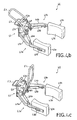
- Figs. 4a-4c show perspective views to a clamping device 41 according to the invention in different conditions.
- the clamping device 41 comprises a bearing frame 42, and two clamping elements 43a 43b, pivotally connected to the bearing frame 42.
- Each clamping element 43a, 43b comprises an arm 44a, 44b, and a pad 45a, 45b connected in a freely rotatable manner to the arm 44a, 44b.
- the pads 45a, 45b are designed for engaging a body of a care-needing person.
- the clamping device 41 also comprises two (gas)draw springs 46a, 46b, while each draw spring 46a, 46b is connected, on the one side, to an arm 44a, 44b associated therewith and is connected on the other side to a second eccentric lobe of an axially rotatable drive shaft 47 forming part of the bearing frame 42.
- the draw springs 46a, 46b are designed for moving the clamping elements 43a, 43b towards the person so that the pads 45a, 45b can be placed in an appropriate manner against the person to be moved.
- the draw springs 46a, 46b are independently of each other manually unlockable by means of two first operating handles 48a, 48b.
- the clamping device 41 further comprises a (gas)draw spring 49 which is connected, on one side, with a stationary part 50 of the bearing frame 42 and connected, on the other side, to a first eccentric lobe of the axially rotatable drive shaft 47 of the bearing frame 42.
- the clamping device 41 further comprises a second operating handle 51 connected to the drive shaft 47, which second operating handle 51 can be locked by means of two locking elements 52a, 52b with respect to the stationary part 50 of the bearing frame 42.
- the locking elements 52a, 52b are mutually connected by means of a third operating handle 53.
- the operation of the clamping device 41 can be described as follows.
- the arms 44a, 44b are represented in an extreme position.
- the person to be moved can be positioned between the arms 44a, 44b and in particular between the pads 45a, 45b.
- the first operating handles 48a, 48b are squeezed by, for instance, a care worker for unlocking the draw springs 46a, 46b so that the arms 44a, 44b will pivot in the direction of the person ( Fig. 4b ) and will exert a slight bias of, for instance, 1 kg on the person.
- the operating handles 48a, 48b will be released again so that the draw springs 46a, 46b are locked in this intermediate position.
- This quasi stable condition is particularly suitable for positioning the pads 45a, 45b against the person in a correct manner.
- the clamping device 41 can clamp the person in a (substantially) firmer manner by unlocking the second operating handle 51 through downward pivoting of the third operating handle 53 with respect to the stationary part 50 of the bearing frame 42.
- the result of the unlocking of the second operating handle 51 is that, as a result of rotation of the drive shaft 47m through the tension spring 49, the second operating handle 51 will pivot in upward direction.
- the rotation of the drive shaft 47 also effects that the arms 44a, 44b are pulled closer together and the person will thus be more firmly clamped ( Figs. 4c ).
- Figs. 5a and 5b show schematic side views to an alternative clamping device 22 in different conditions.
- This alternative clamping device is not an embodiment of the present invention.
- the clamping device 22 comprises a bearing frame 23 built up from several mutually pivotally connected bearing segments 23a-23d.
- the clamping device 22 further comprises two pairs of clamping elements 24, 25 while each pair of clamping elements 24, 25 is freely rotatably connected to a respective bearing segment 23a, 23b.
- a bearing frame can be conceived that is provided with a guide with which a first set of clamping elements and a second set of clamping elements are movably connected to each other so that the mutual distance between the two sets can be adjusted.
- the position of the guide itself with respect to the solid world can also be variable, so that the patient can be tilted through tilting the guide. It will be clear that with such a configuration, the patient can also be brought from a seated to a lying position and vice versa. All this is possible while maintaining a firm clamping and the paths of the trunk and the upper legs are accurately defined by the paths travelled by the first set and the second set of clamping elements.
- the base structure of the hoist can also be attached to the ceiling or to a wall.
- the base structure may be wheeled along a rails provided against or in the ceiling.
Landscapes
- Health & Medical Sciences (AREA)
- Life Sciences & Earth Sciences (AREA)
- Animal Behavior & Ethology (AREA)
- General Health & Medical Sciences (AREA)
- Public Health (AREA)
- Veterinary Medicine (AREA)
- Nursing (AREA)
- Invalid Beds And Related Equipment (AREA)
- Orthopedics, Nursing, And Contraception (AREA)
Applications Claiming Priority (2)
| Application Number | Priority Date | Filing Date | Title |
|---|---|---|---|
| NL2001474A NL2001474C2 (nl) | 2008-04-11 | 2008-04-11 | Kleminrichting ten gebruike in een tillift voor het verplaatsen van personen. |
| PCT/NL2009/050200 WO2009126040A2 (en) | 2008-04-11 | 2009-04-14 | Hoist provided with a clamping device for moving persons |
Publications (2)
| Publication Number | Publication Date |
|---|---|
| EP2291162A2 EP2291162A2 (en) | 2011-03-09 |
| EP2291162B1 true EP2291162B1 (en) | 2012-08-29 |
Family
ID=39945519
Family Applications (1)
| Application Number | Title | Priority Date | Filing Date |
|---|---|---|---|
| EP09729523A Not-in-force EP2291162B1 (en) | 2008-04-11 | 2009-04-14 | Hoist provided with a clamping device for moving persons |
Country Status (5)
| Country | Link |
|---|---|
| US (1) | US8650677B2 (da) |
| EP (1) | EP2291162B1 (da) |
| DK (1) | DK2291162T3 (da) |
| NL (1) | NL2001474C2 (da) |
| WO (1) | WO2009126040A2 (da) |
Families Citing this family (34)
| Publication number | Priority date | Publication date | Assignee | Title |
|---|---|---|---|---|
| GB2462585B (en) * | 2008-07-31 | 2011-04-20 | Simon Christopher Dornton Walker | Universal patient lifting frame |
| JP5556903B2 (ja) * | 2010-12-28 | 2014-07-23 | トヨタ自動車株式会社 | 移乗支援装置及びその作動方法 |
| US9161871B2 (en) * | 2011-01-06 | 2015-10-20 | Community Products, Llc | Multiple function patient handling devices and methods |
| WO2013028961A1 (en) * | 2011-08-24 | 2013-02-28 | Hill-Rom Services, Inc. | Patient stand assist, therapy devices, and methods |
| US20140331399A1 (en) * | 2011-11-15 | 2014-11-13 | Global Lift Corporation | Pool Lift Portability Method and Apparatus |
| JP5981158B2 (ja) * | 2012-02-10 | 2016-08-31 | 富士機械製造株式会社 | 立ち座り動作支援ロボットおよび動作設定方法 |
| ES2459866B1 (es) * | 2012-10-11 | 2015-02-17 | Consejo Superior De Investigaciones Científicas (Csic) | Andador con mecanismo de asistencia en operaciones de levantado y sentado de un usuario. |
| US10166159B2 (en) * | 2013-02-07 | 2019-01-01 | Fuji Corporation | Care robot |
| KR101358943B1 (ko) * | 2013-02-12 | 2014-02-07 | 한국과학기술연구원 | 보행 재활 로봇의 골반 지지 장치 |
| US10143606B2 (en) * | 2013-02-15 | 2018-12-04 | Debby Elnatan | Sit-to-stand apparatus and method |
| DK177674B1 (da) | 2013-03-26 | 2014-02-17 | Revac Aps | Apparat og fremgangsmåde til at bistå personer med funktionsnedsættelse eller handicappede personer |
| DK178035B1 (en) | 2013-03-26 | 2015-04-07 | Revac Aps | Apparatus and method for assisting impaired or disabled persons |
| DK177734B1 (en) | 2013-03-26 | 2014-05-05 | Revac Aps | Apparatus and method for assisting impaired or disabled persons |
| NL2010535C2 (nl) | 2013-03-28 | 2014-09-30 | Indes Holding Bv | Tillift voor het heffen van een patiënt. |
| JP6318503B2 (ja) * | 2013-09-02 | 2018-05-09 | 株式会社今仙電機製作所 | 立ち上がり補助装置 |
| WO2015054229A1 (en) * | 2013-10-07 | 2015-04-16 | Tekulve Daniel R | Portable rehab station |
| JP6481868B2 (ja) * | 2014-09-19 | 2019-03-13 | パナソニックIpマネジメント株式会社 | 起立動作支援システム、起立動作支援システムの作動方法、起立動作支援システムの制御部用プログラム、ロボット |
| TW201622677A (zh) * | 2014-09-19 | 2016-07-01 | Panasonic Ip Man Co Ltd | 起立動作支援系統、起立動作支援系統之控制部的控制方法、起立動作支援系統之控制部用程式、照護帶、機器人 |
| JP6448511B2 (ja) * | 2014-11-11 | 2019-01-09 | 社会福祉法人天寿会 | 移乗機 |
| EP3064187A1 (en) * | 2015-03-06 | 2016-09-07 | ArjoHuntleigh AB | Patient transfer and training aid |
| JP6314952B2 (ja) * | 2015-10-08 | 2018-04-25 | トヨタ自動車株式会社 | 移乗支援装置 |
| US10238564B2 (en) * | 2015-12-27 | 2019-03-26 | Mohammad Fakhrizadeh | Portable assistive lift |
| GB2558239A (en) * | 2016-12-22 | 2018-07-11 | Mallisho Amjad | An apparatus for transporting a patient |
| BE1026327B1 (nl) * | 2018-05-30 | 2020-01-13 | Handi Move Int Nv | Stalift met handgreep |
| US11771606B2 (en) * | 2018-09-20 | 2023-10-03 | Caleigh M. Waskowicz | Ambulatory assist device |
| WO2020118387A1 (pt) * | 2018-12-11 | 2020-06-18 | 2A Hospitalar Comércio E Assistência Técnica De Materiais E Equipamentos Hospitalares Eireli | Movimentador e elevador de pacientes, sistema de conexão a um ciclo ergômetro e seu uso |
| DE102018133234A1 (de) * | 2018-12-20 | 2020-06-25 | BEKA Hospitec GmbH | Aufrichthilfe zum Aufrichten einer Person |
| AU2020218862B2 (en) * | 2019-02-06 | 2025-09-04 | Invacare International Gmbh | Patient lift apparatus |
| WO2020208832A1 (ja) * | 2019-04-12 | 2020-10-15 | 株式会社Fuji | 介助装置 |
| JP7213999B2 (ja) * | 2019-09-12 | 2023-01-27 | 株式会社Fuji | 介助装置 |
| DE102020116445A1 (de) | 2020-06-22 | 2021-12-23 | BEKA Hospitec GmbH | Aufrichthilfe zum Aufrichten einer Person |
| CN112793642B (zh) * | 2021-01-20 | 2022-07-12 | 广东技术师范大学 | 一种省力助老扶起装置及方法 |
| JP7629381B2 (ja) * | 2021-10-22 | 2025-02-13 | 本田技研工業株式会社 | 立ち上がり補助機 |
| US12533275B2 (en) * | 2022-06-24 | 2026-01-27 | Sean Brink | Motorized patient transfer device |
Family Cites Families (18)
| Publication number | Priority date | Publication date | Assignee | Title |
|---|---|---|---|---|
| US3596298A (en) * | 1969-05-14 | 1971-08-03 | John A Durst Jr | Lifting device |
| FR2274273A1 (fr) * | 1974-06-17 | 1976-01-09 | Bakker Anna Christina | Accouplement demontable |
| US4141094A (en) * | 1976-10-27 | 1979-02-27 | Reme Enterprises, Inc. | Increased mobility apparatus for the disabled |
| US5001789A (en) * | 1989-12-05 | 1991-03-26 | Schoenberger Luther V | Invalid lift and transport apparatus |
| US5185895A (en) * | 1992-01-30 | 1993-02-16 | Eugene Gagne | Patient lift and transport aid |
| US5411044A (en) | 1994-04-12 | 1995-05-02 | Andolfi; Alexander S. | Patient transfer walker |
| US5502851A (en) * | 1994-05-26 | 1996-04-02 | Costello; Martin D. | Assisted lifting, stand and walking device |
| DE4431792C1 (de) * | 1994-09-06 | 1995-09-07 | Modie Trans Gmbh | Vorrichtung zum Anheben von Personen |
| NL9500482A (nl) | 1995-03-10 | 1996-10-01 | Careflex Holding Bv | Inrichting en werkwijze voor het oprichten of plaatsen van een persoon. |
| US5892180A (en) * | 1997-02-03 | 1999-04-06 | Medcare Products, L.C. | Patient hoist and scale |
| US6175973B1 (en) * | 1998-07-31 | 2001-01-23 | Hill-Rom, Inc. | Stand assist lift |
| GB9902466D0 (en) * | 1999-02-05 | 1999-03-24 | Arjo Ltd | An invalid lifting device |
| DE20217673U1 (de) * | 2002-11-15 | 2003-02-13 | Hoyer GmbH, 35510 Butzbach | Mobiler Patienten-Aufricht- und Umsetzlift mit Klammer-Achselstützen |
| US7614639B2 (en) * | 2004-10-12 | 2009-11-10 | Invacare Corporation | Modular standing frame |
| JP2009515560A (ja) | 2005-03-14 | 2009-04-16 | エルゴ アシスト テクノロジー リミテッド ライアビリティ カンパニー | 関連フレーム及びリフトカート付き患者移動システム |
| JP2008216443A (ja) * | 2007-03-01 | 2008-09-18 | Ricoh Co Ltd | マグネットローラ及びその製造方法、磁性粒子担持体、現像装置、プロセスカートリッジ、並びに、画像形成装置 |
| US7392554B1 (en) * | 2007-04-27 | 2008-07-01 | Fong-Chin Su | Powered patient lift device |
| JP4687784B2 (ja) * | 2008-12-22 | 2011-05-25 | トヨタ自動車株式会社 | 移乗支援装置及びその制御方法 |
-
2008
- 2008-04-11 NL NL2001474A patent/NL2001474C2/nl not_active IP Right Cessation
-
2009
- 2009-04-14 EP EP09729523A patent/EP2291162B1/en not_active Not-in-force
- 2009-04-14 WO PCT/NL2009/050200 patent/WO2009126040A2/en not_active Ceased
- 2009-04-14 US US12/937,497 patent/US8650677B2/en not_active Expired - Fee Related
- 2009-04-14 DK DK09729523.2T patent/DK2291162T3/da active
Also Published As
| Publication number | Publication date |
|---|---|
| EP2291162A2 (en) | 2011-03-09 |
| NL2001474C2 (nl) | 2009-10-13 |
| DK2291162T3 (da) | 2012-12-10 |
| WO2009126040A3 (en) | 2010-01-14 |
| WO2009126040A2 (en) | 2009-10-15 |
| US8650677B2 (en) | 2014-02-18 |
| US20110056019A1 (en) | 2011-03-10 |
Similar Documents
| Publication | Publication Date | Title |
|---|---|---|
| EP2291162B1 (en) | Hoist provided with a clamping device for moving persons | |
| JP5317111B2 (ja) | 人体把持具とそれを用いた移乗支援器具 | |
| DK2438894T3 (da) | Overførings- og mobilitetsindretning | |
| EP3265043B1 (en) | Patient transfer and training aid | |
| US8151812B2 (en) | Sit down and stand up walker with seat assembly | |
| US10130535B2 (en) | Four bar apparatus and method for lifting, lowering, exercise and self-propelled transit | |
| EP1036552A1 (en) | Lift with pelvic support | |
| CN110996872A (zh) | 包含躯干吊索的手术支架及其使用方法 | |
| JP6362144B2 (ja) | 患者位置変更システム | |
| US20170252602A1 (en) | Supportive exercise machine | |
| EP1617794B1 (en) | Calf and foot support and adjustment assembly | |
| JP2006523512A5 (da) | ||
| EP1773275A2 (en) | An exercise, rehabilitation and mobilization device | |
| CN113101152A (zh) | 一种防摔倒坐站两用的助行车 | |
| CN215606974U (zh) | 一种防摔倒坐站两用的助行车 | |
| CN116831876B (zh) | 一种座椅随动悬停支撑的外骨骼辅助吊架 | |
| KR102673261B1 (ko) | 하체를 부축하는 보행 안전장치 | |
| KR20230102280A (ko) | 체중 지지와 하지 근력 보조가 가능한 보행재활기 | |
| WO2005053593A1 (en) | Apparatus and method for displacing persons from a sitting to a standing position | |
| JP5361812B2 (ja) | 施術用頭部支持装置 | |
| US20260053685A1 (en) | Assistance device equipped with handle and movement device using same | |
| EP3672553B1 (en) | Device to assist in guiding a patient from an upright position beside the bed to a lying position in a bed | |
| DK167205B1 (da) | Kombineret dreje- og staaseng for fysisk staerkt haemmede og svage patienter | |
| JP2018157921A (ja) | 身体支持装置 | |
| JP2006247346A (ja) | 起立補助乃至横臥可変式装置 |
Legal Events
| Date | Code | Title | Description |
|---|---|---|---|
| PUAI | Public reference made under article 153(3) epc to a published international application that has entered the european phase |
Free format text: ORIGINAL CODE: 0009012 |
|
| 17P | Request for examination filed |
Effective date: 20101011 |
|
| AK | Designated contracting states |
Kind code of ref document: A2 Designated state(s): AT BE BG CH CY CZ DE DK EE ES FI FR GB GR HR HU IE IS IT LI LT LU LV MC MK MT NL NO PL PT RO SE SI SK TR |
|
| AX | Request for extension of the european patent |
Extension state: AL BA RS |
|
| DAX | Request for extension of the european patent (deleted) | ||
| REG | Reference to a national code |
Ref country code: DE Ref legal event code: R079 Ref document number: 602009009313 Country of ref document: DE Free format text: PREVIOUS MAIN CLASS: A61G0007100000 Ipc: A61G0005140000 |
|
| GRAP | Despatch of communication of intention to grant a patent |
Free format text: ORIGINAL CODE: EPIDOSNIGR1 |
|
| RIC1 | Information provided on ipc code assigned before grant |
Ipc: A61G 5/14 20060101AFI20120210BHEP Ipc: A61G 7/10 20060101ALI20120210BHEP |
|
| RTI1 | Title (correction) |
Free format text: HOIST PROVIDED WITH A CLAMPING DEVICE FOR MOVING PERSONS |
|
| GRAS | Grant fee paid |
Free format text: ORIGINAL CODE: EPIDOSNIGR3 |
|
| GRAA | (expected) grant |
Free format text: ORIGINAL CODE: 0009210 |
|
| AK | Designated contracting states |
Kind code of ref document: B1 Designated state(s): AT BE BG CH CY CZ DE DK EE ES FI FR GB GR HR HU IE IS IT LI LT LU LV MC MK MT NL NO PL PT RO SE SI SK TR |
|
| REG | Reference to a national code |
Ref country code: GB Ref legal event code: FG4D |
|
| REG | Reference to a national code |
Ref country code: CH Ref legal event code: EP |
|
| REG | Reference to a national code |
Ref country code: AT Ref legal event code: REF Ref document number: 572631 Country of ref document: AT Kind code of ref document: T Effective date: 20120915 |
|
| REG | Reference to a national code |
Ref country code: IE Ref legal event code: FG4D |
|
| REG | Reference to a national code |
Ref country code: DE Ref legal event code: R096 Ref document number: 602009009313 Country of ref document: DE Effective date: 20121025 |
|
| REG | Reference to a national code |
Ref country code: DK Ref legal event code: T3 |
|
| REG | Reference to a national code |
Ref country code: SE Ref legal event code: TRGR |
|
| REG | Reference to a national code |
Ref country code: NL Ref legal event code: T3 |
|
| REG | Reference to a national code |
Ref country code: AT Ref legal event code: MK05 Ref document number: 572631 Country of ref document: AT Kind code of ref document: T Effective date: 20120829 |
|
| REG | Reference to a national code |
Ref country code: LT Ref legal event code: MG4D Effective date: 20120829 |
|
| PG25 | Lapsed in a contracting state [announced via postgrant information from national office to epo] |
Ref country code: FI Free format text: LAPSE BECAUSE OF FAILURE TO SUBMIT A TRANSLATION OF THE DESCRIPTION OR TO PAY THE FEE WITHIN THE PRESCRIBED TIME-LIMIT Effective date: 20120829 Ref country code: HR Free format text: LAPSE BECAUSE OF FAILURE TO SUBMIT A TRANSLATION OF THE DESCRIPTION OR TO PAY THE FEE WITHIN THE PRESCRIBED TIME-LIMIT Effective date: 20120829 Ref country code: NO Free format text: LAPSE BECAUSE OF FAILURE TO SUBMIT A TRANSLATION OF THE DESCRIPTION OR TO PAY THE FEE WITHIN THE PRESCRIBED TIME-LIMIT Effective date: 20121129 Ref country code: IS Free format text: LAPSE BECAUSE OF FAILURE TO SUBMIT A TRANSLATION OF THE DESCRIPTION OR TO PAY THE FEE WITHIN THE PRESCRIBED TIME-LIMIT Effective date: 20121229 Ref country code: AT Free format text: LAPSE BECAUSE OF FAILURE TO SUBMIT A TRANSLATION OF THE DESCRIPTION OR TO PAY THE FEE WITHIN THE PRESCRIBED TIME-LIMIT Effective date: 20120829 Ref country code: LT Free format text: LAPSE BECAUSE OF FAILURE TO SUBMIT A TRANSLATION OF THE DESCRIPTION OR TO PAY THE FEE WITHIN THE PRESCRIBED TIME-LIMIT Effective date: 20120829 |
|
| PG25 | Lapsed in a contracting state [announced via postgrant information from national office to epo] |
Ref country code: LV Free format text: LAPSE BECAUSE OF FAILURE TO SUBMIT A TRANSLATION OF THE DESCRIPTION OR TO PAY THE FEE WITHIN THE PRESCRIBED TIME-LIMIT Effective date: 20120829 Ref country code: PT Free format text: LAPSE BECAUSE OF FAILURE TO SUBMIT A TRANSLATION OF THE DESCRIPTION OR TO PAY THE FEE WITHIN THE PRESCRIBED TIME-LIMIT Effective date: 20121231 Ref country code: SI Free format text: LAPSE BECAUSE OF FAILURE TO SUBMIT A TRANSLATION OF THE DESCRIPTION OR TO PAY THE FEE WITHIN THE PRESCRIBED TIME-LIMIT Effective date: 20120829 Ref country code: GR Free format text: LAPSE BECAUSE OF FAILURE TO SUBMIT A TRANSLATION OF THE DESCRIPTION OR TO PAY THE FEE WITHIN THE PRESCRIBED TIME-LIMIT Effective date: 20121130 Ref country code: BE Free format text: LAPSE BECAUSE OF FAILURE TO SUBMIT A TRANSLATION OF THE DESCRIPTION OR TO PAY THE FEE WITHIN THE PRESCRIBED TIME-LIMIT Effective date: 20120829 |
|
| PG25 | Lapsed in a contracting state [announced via postgrant information from national office to epo] |
Ref country code: RO Free format text: LAPSE BECAUSE OF FAILURE TO SUBMIT A TRANSLATION OF THE DESCRIPTION OR TO PAY THE FEE WITHIN THE PRESCRIBED TIME-LIMIT Effective date: 20120829 Ref country code: EE Free format text: LAPSE BECAUSE OF FAILURE TO SUBMIT A TRANSLATION OF THE DESCRIPTION OR TO PAY THE FEE WITHIN THE PRESCRIBED TIME-LIMIT Effective date: 20120829 Ref country code: CZ Free format text: LAPSE BECAUSE OF FAILURE TO SUBMIT A TRANSLATION OF THE DESCRIPTION OR TO PAY THE FEE WITHIN THE PRESCRIBED TIME-LIMIT Effective date: 20120829 Ref country code: ES Free format text: LAPSE BECAUSE OF FAILURE TO SUBMIT A TRANSLATION OF THE DESCRIPTION OR TO PAY THE FEE WITHIN THE PRESCRIBED TIME-LIMIT Effective date: 20121210 |
|
| PG25 | Lapsed in a contracting state [announced via postgrant information from national office to epo] |
Ref country code: SK Free format text: LAPSE BECAUSE OF FAILURE TO SUBMIT A TRANSLATION OF THE DESCRIPTION OR TO PAY THE FEE WITHIN THE PRESCRIBED TIME-LIMIT Effective date: 20120829 Ref country code: PL Free format text: LAPSE BECAUSE OF FAILURE TO SUBMIT A TRANSLATION OF THE DESCRIPTION OR TO PAY THE FEE WITHIN THE PRESCRIBED TIME-LIMIT Effective date: 20120829 Ref country code: IT Free format text: LAPSE BECAUSE OF FAILURE TO SUBMIT A TRANSLATION OF THE DESCRIPTION OR TO PAY THE FEE WITHIN THE PRESCRIBED TIME-LIMIT Effective date: 20120829 |
|
| PLBE | No opposition filed within time limit |
Free format text: ORIGINAL CODE: 0009261 |
|
| STAA | Information on the status of an ep patent application or granted ep patent |
Free format text: STATUS: NO OPPOSITION FILED WITHIN TIME LIMIT |
|
| PG25 | Lapsed in a contracting state [announced via postgrant information from national office to epo] |
Ref country code: BG Free format text: LAPSE BECAUSE OF FAILURE TO SUBMIT A TRANSLATION OF THE DESCRIPTION OR TO PAY THE FEE WITHIN THE PRESCRIBED TIME-LIMIT Effective date: 20121129 |
|
| 26N | No opposition filed |
Effective date: 20130530 |
|
| REG | Reference to a national code |
Ref country code: DE Ref legal event code: R097 Ref document number: 602009009313 Country of ref document: DE Effective date: 20130530 |
|
| PG25 | Lapsed in a contracting state [announced via postgrant information from national office to epo] |
Ref country code: MC Free format text: LAPSE BECAUSE OF FAILURE TO SUBMIT A TRANSLATION OF THE DESCRIPTION OR TO PAY THE FEE WITHIN THE PRESCRIBED TIME-LIMIT Effective date: 20120829 Ref country code: CY Free format text: LAPSE BECAUSE OF FAILURE TO SUBMIT A TRANSLATION OF THE DESCRIPTION OR TO PAY THE FEE WITHIN THE PRESCRIBED TIME-LIMIT Effective date: 20120829 |
|
| REG | Reference to a national code |
Ref country code: CH Ref legal event code: PL |
|
| REG | Reference to a national code |
Ref country code: IE Ref legal event code: MM4A |
|
| PG25 | Lapsed in a contracting state [announced via postgrant information from national office to epo] |
Ref country code: CH Free format text: LAPSE BECAUSE OF NON-PAYMENT OF DUE FEES Effective date: 20130430 Ref country code: LI Free format text: LAPSE BECAUSE OF NON-PAYMENT OF DUE FEES Effective date: 20130430 |
|
| PG25 | Lapsed in a contracting state [announced via postgrant information from national office to epo] |
Ref country code: IE Free format text: LAPSE BECAUSE OF NON-PAYMENT OF DUE FEES Effective date: 20130414 |
|
| PG25 | Lapsed in a contracting state [announced via postgrant information from national office to epo] |
Ref country code: MT Free format text: LAPSE BECAUSE OF FAILURE TO SUBMIT A TRANSLATION OF THE DESCRIPTION OR TO PAY THE FEE WITHIN THE PRESCRIBED TIME-LIMIT Effective date: 20120829 |
|
| PG25 | Lapsed in a contracting state [announced via postgrant information from national office to epo] |
Ref country code: TR Free format text: LAPSE BECAUSE OF FAILURE TO SUBMIT A TRANSLATION OF THE DESCRIPTION OR TO PAY THE FEE WITHIN THE PRESCRIBED TIME-LIMIT Effective date: 20120829 |
|
| PG25 | Lapsed in a contracting state [announced via postgrant information from national office to epo] |
Ref country code: HU Free format text: LAPSE BECAUSE OF FAILURE TO SUBMIT A TRANSLATION OF THE DESCRIPTION OR TO PAY THE FEE WITHIN THE PRESCRIBED TIME-LIMIT; INVALID AB INITIO Effective date: 20090414 Ref country code: LU Free format text: LAPSE BECAUSE OF NON-PAYMENT OF DUE FEES Effective date: 20130414 Ref country code: MK Free format text: LAPSE BECAUSE OF FAILURE TO SUBMIT A TRANSLATION OF THE DESCRIPTION OR TO PAY THE FEE WITHIN THE PRESCRIBED TIME-LIMIT Effective date: 20120829 |
|
| REG | Reference to a national code |
Ref country code: FR Ref legal event code: PLFP Year of fee payment: 8 |
|
| REG | Reference to a national code |
Ref country code: FR Ref legal event code: PLFP Year of fee payment: 9 |
|
| PGFP | Annual fee paid to national office [announced via postgrant information from national office to epo] |
Ref country code: NL Payment date: 20170331 Year of fee payment: 9 |
|
| PGFP | Annual fee paid to national office [announced via postgrant information from national office to epo] |
Ref country code: GB Payment date: 20170419 Year of fee payment: 9 Ref country code: DK Payment date: 20170419 Year of fee payment: 9 Ref country code: DE Payment date: 20170419 Year of fee payment: 9 Ref country code: FR Payment date: 20170419 Year of fee payment: 9 |
|
| PGFP | Annual fee paid to national office [announced via postgrant information from national office to epo] |
Ref country code: SE Payment date: 20170419 Year of fee payment: 9 |
|
| REG | Reference to a national code |
Ref country code: DE Ref legal event code: R119 Ref document number: 602009009313 Country of ref document: DE |
|
| REG | Reference to a national code |
Ref country code: DK Ref legal event code: EBP Effective date: 20180430 |
|
| REG | Reference to a national code |
Ref country code: SE Ref legal event code: EUG |
|
| REG | Reference to a national code |
Ref country code: NL Ref legal event code: MM Effective date: 20180501 |
|
| GBPC | Gb: european patent ceased through non-payment of renewal fee |
Effective date: 20180414 |
|
| PG25 | Lapsed in a contracting state [announced via postgrant information from national office to epo] |
Ref country code: SE Free format text: LAPSE BECAUSE OF NON-PAYMENT OF DUE FEES Effective date: 20180415 Ref country code: NL Free format text: LAPSE BECAUSE OF NON-PAYMENT OF DUE FEES Effective date: 20180501 Ref country code: DE Free format text: LAPSE BECAUSE OF NON-PAYMENT OF DUE FEES Effective date: 20181101 |
|
| PG25 | Lapsed in a contracting state [announced via postgrant information from national office to epo] |
Ref country code: GB Free format text: LAPSE BECAUSE OF NON-PAYMENT OF DUE FEES Effective date: 20180414 |
|
| PG25 | Lapsed in a contracting state [announced via postgrant information from national office to epo] |
Ref country code: FR Free format text: LAPSE BECAUSE OF NON-PAYMENT OF DUE FEES Effective date: 20180430 |
|
| PG25 | Lapsed in a contracting state [announced via postgrant information from national office to epo] |
Ref country code: DK Free format text: LAPSE BECAUSE OF NON-PAYMENT OF DUE FEES Effective date: 20180430 |