EP2291268B1 - Zusammenklappbarer rollstützständer mit stützbein - Google Patents
Zusammenklappbarer rollstützständer mit stützbein Download PDFInfo
- Publication number
- EP2291268B1 EP2291268B1 EP09751094.5A EP09751094A EP2291268B1 EP 2291268 B1 EP2291268 B1 EP 2291268B1 EP 09751094 A EP09751094 A EP 09751094A EP 2291268 B1 EP2291268 B1 EP 2291268B1
- Authority
- EP
- European Patent Office
- Prior art keywords
- stand
- members
- top frame
- rolling stand
- collapsible rolling
- Prior art date
- Legal status (The legal status is an assumption and is not a legal conclusion. Google has not performed a legal analysis and makes no representation as to the accuracy of the status listed.)
- Active
Links
Images



Classifications
-
- B—PERFORMING OPERATIONS; TRANSPORTING
- B25—HAND TOOLS; PORTABLE POWER-DRIVEN TOOLS; MANIPULATORS
- B25H—WORKSHOP EQUIPMENT, e.g. FOR MARKING-OUT WORK; STORAGE MEANS FOR WORKSHOPS
- B25H1/00—Work benches; Portable stands or supports for positioning portable tools or work to be operated on thereby
- B25H1/02—Work benches; Portable stands or supports for positioning portable tools or work to be operated on thereby of table type
- B25H1/04—Work benches; Portable stands or supports for positioning portable tools or work to be operated on thereby of table type portable
-
- Y—GENERAL TAGGING OF NEW TECHNOLOGICAL DEVELOPMENTS; GENERAL TAGGING OF CROSS-SECTIONAL TECHNOLOGIES SPANNING OVER SEVERAL SECTIONS OF THE IPC; TECHNICAL SUBJECTS COVERED BY FORMER USPC CROSS-REFERENCE ART COLLECTIONS [XRACs] AND DIGESTS
- Y10—TECHNICAL SUBJECTS COVERED BY FORMER USPC
- Y10T—TECHNICAL SUBJECTS COVERED BY FORMER US CLASSIFICATION
- Y10T70/00—Locks
- Y10T70/50—Special application
- Y10T70/5611—For control and machine elements
- Y10T70/569—Lever
- Y10T70/573—Single
Definitions
- the present invention generally relates to rolling support stands.
- Rolling hand trucks or support stands for large and/or heavy objects have been known for decades and are useful for transporting such objects from one location to another. Some of such known support stands are collapsible to some degree and many different designs of the hand trucks or rolling support stands are particularly suited for specific uses. While such products may be used in many different industries and applications, one noteworthy use is that of transporting objects, such as portable table saws, miter saws and the like to and from construction sites.
- carpenters In the home building trade, carpenters generally have table saws as well as other types of saws that are brought to a jobsite every day in the tradesman's truck or are stored in a secure location at the jobsite and must be removed from the truck or stored location and be set up on the jobsite while work is being done. At the end of the work day, the tradesman must pack up the saw and return it to his truck or secure location for safe keeping. Because such tools are valuable, they cannot be left unattended overnight without a significant risk of theft.
- stands may unfold using a spring biasing mechanism that is released and which then supplies a major force tending to place the stand with the saw attached to it in its proper working generally horizontal position.
- stands of this type may be dangerous if the folded stand has the mechanism released when the weight of the saw is not over the stand mechanism. If there is no load on the mechanism, it can unfold very rapidly which can be quite dangerous if a tradesman or any other person is struck by the mechanism.
- US 5,542,639 discloses an apparatus for supporting an object which includes at least two leg members attached to and capable of folding under an object-supporting surface.
- the leg members are pivotally attached to the object-supporting surface so that the leg members may fold under the object-supporting surface without interfering with one another.
- EP 1 847 358 A2 discloses a collapsible folding stand for use with a portable power tool or other object that is attached to the stand and is capable of being manipulated between open and closed positions.
- a preferred embodiment of the present invention comprises a collapsible folding stand for use with a horizontally oriented object such as a portable table saw or miter saw that is attached to the stand wherein the stand has a front and a rear portion and is capable of being manipulated between open and closed positions.
- the top frame In the open position, the top frame is horizontally oriented.
- the stand In the closed position, the stand is generally vertically oriented as is the top frame. To move the rolling stand from its open position to its closed position, the user needs only to lift the handle and the top frame will then move to its generally vertical closed position where the latching mechanism can then be engaged. Because of the mechanism advantage of the folding mechanism, moving between the open and closed positions in either direction requires very little effort by the user.
- the preferred embodiment has an integrated support leg that can be selectively positioned and locked to provide increased stability and rigidity for the stand.
- the support leg has a locking mechanism, which when unlocked does not impede the easy movement between open and closed positions in either direction, and which when locked in the open position provides additional stability to the stand.
- the locking mechanism is operated by a single locking lever and can be adjusted to compensate for wear or degree of force needed to lock the mechanism.
- the preferred embodiment of the collapsible rolling stand of the present invention has a top frame upon which an object such as a table saw, miter saw or the like can be attached and a folding mechanism that includes at least first and second members that are pivotable relative to one another and which resemble a scissor movement, with the center of gravity of the object that is attached to the top frame being located between the ground contacting ends of each of the first and second members.
- This enables the weight of the object to assist the unfolding of the stand which causes the object to move from a generally vertically oriented position to a generally horizontal position. Because the center of gravity of the object is between the ground contacting ends of the first and second members, the stand can be easily folded back to the collapsed generally vertical position without significant exertion by a user performing either operation.
- the user does not have to provide any heavy lifting in order to set up or break down the stand with the object attached to it.
- a user can completely set up or knock down the stand by holding the handle and gently urging it in one direction or the other to open or close it. It is only necessary to manipulate a locking mechanism to release it from a closed position and to lock it when it has been moved from an opened position to its closed position.
- the preferred embodiment of the present invention is a stand for relatively heavy objects, such as commercial grade portable table saws that can weigh upwards of 60 pounds or more, there are relatively large forces that are acting on the components of the stand, and the preferred embodiment of the present invention comprises a support leg that is configured to provide increased stability and rigidity for the stand.
- the support leg has a locking mechanism, which when unlocked does not impede the easy movement between open and closed positions in either direction, and which when locked in the open position provides additional stability to the stand.
- the locking mechanism utilizes a single locking lever and can be adjusted to compensate for wear or degree of force needed to lock the mechanism.
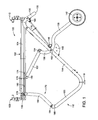
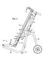
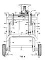
- a preferred embodiment of a rolling stand indicated generally at 100 which has a top frame structure, indicated generally at 102, that comprises side members 104 as well as a front member 106.
- Two mounting structures 108 and 110 are attached to the frame structure 102 and are configured to engage and hold a table saw that is mounted on the top 102 frame structure.
- the embodiment 100 also has a folding mechanism, indicated generally at 112, that includes a main side strut 114 that is pivotally attached to the top frame structure 102 by pivot connection 116 and extends downwardly to a ground contact 118.
- a transverse extension 120 is also provided and it has an end bridge 122 that interconnects the extension 120 of each side.
- the main side strut 114 extends upwardly to the connections 116 beyond which they are formed into generally transverse handle extension 130 that merges with a curved handle 132.
- the handle 132 has a general upward curve as shown in FIG. 5 of the drawings, which is not only ergonomically convenient, but also defines two lower contact points 134 that may facilitate the stand being loaded onto an elevated platform such as a cargo floor of a truck or van.
- This embodiment also has a pair of rear legs 136 with curved leg extensions 138 that is angled relative to the rear legs 136.
- the rear legs 136 also have a wheel 142 attached to the end portion of each side thereof.
- a rear end brace 144 is provided to interconnect the rear legs 136.
- Each of the rear legs 136 have a curved auxiliary support plate 146 that is attached to the rear leg 136 and the leg extension 138 and this support member has an inwardly directed stop member 148 that is positioned to engage the main side strut 114 when it reaches its open position as best shown in FIG. 1 .
- Each rear leg 136 is pivotally connected to the side strut 114 by pivot connection 150.
- a link member 152 is also provided in this embodiment and it has a pivot connection 154 to the end of the rear leg extension 138 and a pivot connection 156 for connecting to the side member 104 of the top frame.
- the handle 134 When the rolling stand 100 shown in its open position in FIG. 1 is to be moved to its closed position, the handle 134 must be raised to move the side strut 114 upwardly.
- the rear leg 136 will then pivot in a clockwise direction around pivot point 150 so that the wheel 142 will begin to approach the lower contact point 118 during the closing operation.
- the rear leg extension 136 will move pivot point 154 in a clockwise direction relative to pivot point 150 and cause the front end of the stand to move downwardly so that end 106 will move in a counterclockwise direction pivoting around the opposite pivot connection 116, resulting in the end 106 approaching the lower end of the side strut 114.
- the stand is shown in an intermediate position in FIG. 2 and a fully closed position in FIG. 3 . From the vertical closed position the opposite series of movements will occur as has been described to return to a horizontal open position shown in FIG. 1 .
- a latching mechanism including a rotatable lever 160 may be provided to lock the stand in its fully open as well as
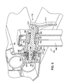
- the preferred embodiment includes an integrated support leg structure, indicated generally at 170, and is shown in all of the drawings and in detail in FIGS. 5-8 .
- the side members 104 are preferably a relatively complex aluminum extrusion that includes a generally square channel 172 having an outer side slot 174 extending substantially the full length of the side member, although it only needs to be open for the length of a guide track 176 which is installed in the channel 172, and in which a locking mechanism, indicated generally at 178, can slide.
- the guide track 176 is stationary in the channel and may be held in place by a friction fit, or by crimping, or by a set screw or other fastener.
- the guide track 176 has a closed ended slot 180 and is configured to receive a component of the locking mechanism 178.
- the locking mechanism 178 has components that extend through the slot 174 in the channel 172 as well as the slot 180 in the guide track 176, thereby enabling the locking mechanism to slide relative to the side member 104 when the locking mechanism 178 is unlocked and it is desired to move the stand from its closed position to its open position or vice versa.
- the support leg structure 170 has a support leg 182 that has the locking mechanism 178 at its upper end as shown in FIG. 1 and a lower end pivotally attached by pivot connection 184 to a mounting bracket 186 that is connected to the bridge portion 122.
- the mounting bracket 186 can be welded to the bridge portion or may be mechanically attached to it with bolts, clamps or other fastening mechanism.
- the support leg structure 170 therefore provides a support to the front of the top 102 and gives the stand 100 more rigidity and stability.
- the leg 182 is preferably angled by approximately 20° as shown so that when it is in its support position as shown in FIG. 1 , the load is applied generally vertically on the locking mechanism 178 rather than at an angle which would possibly contribute to the locking mechanism and upper end of the leg 182 sliding to the right as shown in FIG. 1 .
- the stand can be moved from the open position, shown for example in FIG. 1 , to the closed position wherein the locking mechanism 178 will slide along the side member as shown in FIGS. 2 and 3 .
- the mechanism includes a cylindrical upper end portion 188 that is preferably formed as part of the leg 182, but may be a separate cylindrical structure that would be attached through an opening in the upper end portion of the leg 182 and attached thereto.
- a release shaft 190 that has a center portion 192 that is enlarged relative to an outer end portion 194 and an inner end portion 196.
- the intersection of the center portion 190 and the outer end portion 194 defines an annular shoulder 198 and the intersection of the center portion 190 and the inner end portion 196 forms an annular shoulder 200.
- the outer diameter of the center portion 190 is slightly less than the inner diameter of the cylindrical portion 188 and is free to slide within it to lock and unlock the mechanism.
- the inner end portion 196 has threads 202 for receiving a nylon nut 204, the inner face of which engages a nylon washer 206 that abuts a T-roller 208 that is rotatable on the inner end portion 196 and has an outer surface that rides in the slot 180 of the guide track 176.
- the cylindrical end portion 188 has an inner face 208 that engages a preferably nylon washer 210 for protecting the extruded aluminum side member 104.
- the nylon components also exhibit lesser frictional resistance when sliding in the aluminum channel.
- a spring 212 is provided and bears against the inside end surface of the cylindrical end portion 188 and the shoulder 198 and urges the release shaft 190 to the left as shown in FIG. 6 .
- a cam lever 214 is pivotally connected to the outer end portion 195 by a roll pin 216 and is shown in a locked position in FIG. 6 and an unlocked position in FIG. 7 .
- the cam lever is shown in cross-section in FIG. 8 and has an aperture 218 in which the roll pin 216 fits.
- the distance between the outside of the bottom surface 220 and the center of the aperture 218, marked as distance A is less than the distance from the center of the aperture 218 to the side of the contact surface 222 which means that when the cam lever 218 is moved from its unlocked position in FIG. 7 to its locked position in FIG.
- the spring 212 urges the release shaft 190 toward its unlocked position so that when the cam lever 214 is moved to the position shown in FIG. 7 , the entire locking mechanism 178 is free to slide within the slots 174 and 180.
- a further embodiment provides a collapsible rolling stand for use with an elongated normally horizontally oriented heavy object attached thereto, said stand being supported by a ground surface and having a front end portion and a rear end portion, and being capable of being manipulated between open and closed positions, wherein the object is generally vertically oriented when the stand is closed, and wherein the object is generally horizontally oriented when the stand is in its open position, said stand comprising:
Landscapes
- Engineering & Computer Science (AREA)
- Mechanical Engineering (AREA)
- Handcart (AREA)
Claims (17)
- Zusammenklappbarer Rollenarbeitstisch (100) zur Verwendung mit einem länglichen, normalerweise horizontal ausgerichteten, daran angebrachten Objekt, wobei der Arbeitstisch durch eine Bodenfläche gestützt wird und einen Vorderendabschnitt und einen Hinterendabschnitt aufweist und zwischen einer offenen und einer geschlossenen Position verstellt werden kann, wobei das Objekt allgemein vertikal ausgerichtet ist, wenn der Arbeitstisch geschlossen ist, und wobei das Objekt allgemein horizontal ausgerichtet ist, wenn sich der Arbeitstisch in seiner offenen Position befindet, wobei der Arbeitstisch Folgendes umfasst:einen oberen Rahmen (102) mit einem allgemein planaren Abschnitt, der dafür ausgebildet ist, dass das Objekt an ihm befestigt wird, wobei der planare Abschnitt des oberen Rahmens in einer allgemein horizontalen Position ausgerichtet ist, wenn sich der Arbeitstisch in seiner offenen Position befindet, und in einer allgemein vertikalen Position ausgerichtet ist, wenn der Arbeitstisch in seine geschlossene Position bewegt wird;einen Klappmechanismus (112), der den oberen Rahmen stützt und mindestens einen Handgriff (132) umfasst, der mit einem Endabschnitt eines Paares voneinander beabstandeter länglicher erster Elemente (114) wirkverbunden ist, die gegenüberliegende Endabschnitte haben, die Punkte (118) umfassen, welche die Bodenfläche berühren, und ein Paar voneinander beabstandeter zweiter Elemente (136) umfasst, die jeweils Räder (142) aufweisen, die es einem Benutzer erlauben, den Arbeitstisch auf der Bodenfläche zu rollen, wobei die ersten und zweiten Elemente schwenkbar miteinander verbunden sind (150) und so ausgebildet sind, dass das Gewicht des Objekts einen beträchtlichen Teil der nötigen Kraft liefert, die benötigt wird, um das erste und das zweite Paar von Elementen zu schwenken, um den vorderen Kontaktpunkt weiter von den hinteren Rädern (142) zu trennen und den Arbeitstisch von der geschlossenen Position zu der offenen Position zu bewegen, wobei der planare Abschnitt des oberen Rahmens (102) im Wesentlichen horizontal ist; undeinen Stützschenkel (170), der einen ersten Endabschnitt und eine erste Verbindung (184) mit mindestens einem der ersten Elemente (120) aufweist,dadurch gekennzeichnet, dass der Stützschenkel des Weiteren einen zweiten Endabschnitt umfasst, der eine zweite Verbindung mit einem horizontalen länglichen Schlitz (174) aufweist, die sich nahe der Vorderseite des oberen Rahmens (102) befindet,wobei die zweite Verbindung entlang der Länge des Schlitzes (174) gleitet und schwenkt, während der Arbeitstisch zwischen der offenen und der geschlossenen Position verstellt wird, ohne dass der Stützschenkel (170) von dem oberen Rahmen (102) oder von dem ersten Element (120) getrennt wird.
- Zusammenklappbarer Rollenarbeitstisch nach Anspruch 1, wobei der obere Rahmen einen Kanalabschnitt (172) aufweist, wobei der horizontale längliche Schlitz (174) an dessen Vorderseite angeordnet ist, wobei der Kanalabschnitt eine Innenfläche auf gegenüberliegenden Seiten des Schlitzes aufweist.
- Zusammenklappbarer Rollenarbeitstisch nach Anspruch 2, wobei die zweite Verbindung des Weiteren einen Verriegelungsmechanismus (178) umfasst, um die Verbindung an einer gewünschten Position entlang der Länge des Schlitzes (174) zu sichern.
- Zusammenklappbarer Rollenarbeitstisch nach Anspruch 3, wobei der Verriegelungsmechanismus (178) Folgendes umfasst:eine Freigabewelle (190), die in dem zweiten Endabschnitt des Schenkels gleiten kann, wobei die Freigabewelle ein erstes Ende mit einem äußeren Gewinde-Endabschnitt aufweist, das sich in den Schlitz hinein erstreckt,eine Mutter (204), die sich in dem Kanal befindet und auf den äußeren Endabschnitt geschraubt ist;einen schwenkbaren Nockenhebel (214), der an einem zweiten Ende angebracht ist und zwischen einer verriegelten und einer unverriegelten Position beweglich ist.
- Zusammenklappbarer Rollenarbeitstisch nach Anspruch 4, wobei der schwenkbare Nockenhebel (214) den Stützschenkel berührt und an der Freigabewelle (190) zieht, um die Mutter in Eingriff mit dem Innenfläche des Kanalabschnitts (172) zu bringen, wenn der Nockenhebel in die verriegelte Position bewegt wird.
- Zusammenklappbarer Rollenarbeitstisch nach Anspruch 5, wobei der Verriegelungsmechanismus (178) des Weiteren eine Druckfeder (212) umfasst, um die Freigabewelle einwärts in Richtung des Kanalabschnitts vorzuspannen, so dass die Mutter von der Innenfläche fort bewegt wird.
- Zusammenklappbarer Rollenarbeitstisch nach Anspruch 6, wobei ein Ende der Feder (212) an einer Schulter der Freigabewelle (190) anliegt und ein gegenüberliegendes Ende an einer Oberfläche des Stützschenkels anliegt.
- Zusammenklappbarer Rollenarbeitstisch nach Anspruch 1, wobei die erste Verbindung (184) es dem Stützschenkel (170) gestattet, relativ zu dem ersten Element (120) zu schwenken.
- Zusammenklappbarer Rollenarbeitstisch nach Anspruch 1, wobei der Klappmechanismus (112) des Weiteren umfasst, dass:die ersten Elemente (114) auf jeder Seite des Arbeitstisches angeordnet sind und mit einem hinteren Abschnitt des planaren Abschnitts des oberen Rahmens (102) wirkverbunden und relativ dazu schwenkbar sind, jedes der zweiten Elemente (136) eine Schwenkverbindung (150) mit einem der ersten Elemente an einem Punkt zwischen den Enden des ersten Elements aufweist, wobei jedes zweite Element (136) eines der Räder (142) aufweist, das mit seinem hinteren Endabschnitt verbunden ist, und eine Verlängerung (138) aufweist, die vor der Schwenkverbindung in einem zuvor festgelegten Winkel relativ zur Längsrichtung des zweiten Elements angeordnet ist;ein Gestängeelement (152), das schwenkbar am distalen Ende der Verlängerung und an dem planaren Abschnitt des oberen Rahmens angebracht ist;einen Handgriff (132), der mit dem planaren Abschnitt des oberen Rahmens oder den ersten Elementen verbunden ist;einen Verriegelungsmechanismus (160) zum lösbaren Halten des Arbeitstisches in mindestens der geschlossenen Position;wobei, wenn der Arbeitstisch (100) in seiner geschlossenen Position ist, das Betätigen des Verriegelungsmechanismus es dem zweiten Element (136) ermöglicht, um die Schwenkverbindung herum zu schwenken, wodurch bewirkt wird, dass das Gewicht des Objekts die Räder um eine kurze Distanz von dem planaren Abschnitt des oberen Rahmens fort bewegt, wobei eine weitere Bewegung des Arbeitstisch in der Rückwärtsrichtung bewirkt, dass sich die zweiten Elemente und das Rad (142) in Richtung des hinteren Teils des Arbeitstisches in die offene Position drehen, welcher der planare Abschnitt des oberen Rahmens in der im Wesentlichen horizontalen Position ausgerichtet ist.
- Zusammenklappbarer Rollenarbeitstisch nach Anspruch 9, wobei der Handgriff ein Querelement (130) umfasst, das sich zwischen beiden ersten Elementen (114) erstreckt und mit diesen verbunden ist.
- Zusammenklappbarer Rollenarbeitstisch nach Anspruch 10, wobei das Querelement (130) in einer Erhöhung unter dem planaren Abschnitt des oberen Rahmens (102) positioniert ist und eine gekrümmte Form hat, die sich von jedem der ersten Elemente (114) nach oben erstreckt.
- Zusammenklappbarer Rollenarbeitstisch nach Anspruch 11, wobei die ersten Elemente (114) eine allgemein quergerichzete, abwärts gerichtete Erstreckung aufweisen, die über die Schwenkverbindung mit dem oberen Rahmenelement hinaus reicht, wobei der Handgriff mit den Enden jeder abwärts gerichteten Erstreckung verbunden ist.
- Zusammenklappbarer Rollenarbeitstisch nach Anspruch 11, wobei die ersten Elemente (114) und der Handgriff (132) eine integral ausgebildete, einstückige Struktur sind.
- Zusammenklappbarer Rollenarbeitstisch nach Anspruch 9, wobei der Verriegelungsmechanismus (160) einen Gleitstift umfasst, der einen Bedienknauf aufweist, der mit einem der ersten und zweiten Elemente wirkverbunden ist, der dafür ausgebildet ist, die anderen der ersten und zweiten Elemente in Wirkeingriff zu nehmen, wenn sich der Arbeitstisch in mindestens seiner geschlossenen Position befindet.
- Zusammenklappbarer Rollenarbeitstisch nach Anspruch 9, wobei die ersten Elemente (114) eine allgemein quergerichtete Erstreckung an den den Boden berührenden, gegenüberliegenden Enden haben und mindestens eine Vorderendbrücke aufweisen, welche die gegenüberliegenden Enden miteinander verbindet.
- Zusammenklappbarer Rollenarbeitstisch nach Anspruch 1, der des Weiteren eine Feder umfasst, um den Arbeitstisch in Richtung seiner geschlossenen Position vorzuspannen, wenn er sich in seiner offenen Position befindet, dergestalt, dass ein Bediener nicht mehr als eine geringe Kraft ausüben muss, um den Arbeitstisch in seine geschlossene Position zu bewegen.
- Zusammenklappbarer Rollenarbeitstisch nach Anspruch 1, wobei der planare Abschnitt des oberen Rahmens (102) zwei seitliche Rahmenelemente (104) und zwei Endrahmenelemente (106) umfasst, die in einer allgemein planaren rechteckigen Ausgestaltung miteinander verbunden sind.
Applications Claiming Priority (2)
| Application Number | Priority Date | Filing Date | Title |
|---|---|---|---|
| US12856508P | 2008-05-22 | 2008-05-22 | |
| PCT/US2009/041481 WO2009142865A1 (en) | 2008-05-22 | 2009-04-23 | A collapsible rolling support stand having a support leg |
Publications (2)
| Publication Number | Publication Date |
|---|---|
| EP2291268A1 EP2291268A1 (de) | 2011-03-09 |
| EP2291268B1 true EP2291268B1 (de) | 2015-12-02 |
Family
ID=40743879
Family Applications (1)
| Application Number | Title | Priority Date | Filing Date |
|---|---|---|---|
| EP09751094.5A Active EP2291268B1 (de) | 2008-05-22 | 2009-04-23 | Zusammenklappbarer rollstützständer mit stützbein |
Country Status (5)
| Country | Link |
|---|---|
| US (1) | US8047553B2 (de) |
| EP (1) | EP2291268B1 (de) |
| CN (1) | CN102036788B (de) |
| TW (1) | TWI488702B (de) |
| WO (1) | WO2009142865A1 (de) |
Families Citing this family (25)
| Publication number | Priority date | Publication date | Assignee | Title |
|---|---|---|---|---|
| US8047553B2 (en) * | 2008-05-22 | 2011-11-01 | Robert Bosch Gmbh | Collapsible rolling support stand having a support leg |
| US20110043085A1 (en) * | 2009-08-21 | 2011-02-24 | SherpaMax LLC | Portable container and workstation |
| US8454717B2 (en) * | 2010-10-12 | 2013-06-04 | Tony Lin | Foldable dust collector |
| TWI393617B (zh) * | 2010-12-28 | 2013-04-21 | Rexon Ind Corp Ltd | 具有可收折腳架的載台 |
| CN102632492B (zh) * | 2011-02-14 | 2014-10-22 | 力山工业股份有限公司 | 具有可收折脚架的载台 |
| US20120217727A1 (en) * | 2011-02-25 | 2012-08-30 | P & F Brother Industrial Corporation | Wheeled Collapsible Stand for a Power Driven Machine |
| US8910970B2 (en) * | 2011-06-10 | 2014-12-16 | Rexon Industrial Corp., Ltd. | Rapidly collapsible stand |
| EP2845694B1 (de) * | 2013-08-13 | 2017-07-26 | Black & Decker Inc. | Tragbare Werkbank |
| US9776319B2 (en) | 2014-09-02 | 2017-10-03 | Black & Decker Inc. | Portable work bench |
| TWI570348B (zh) * | 2014-12-16 | 2017-02-11 | 力山工業股份有限公司 | 可收折之支撐架 |
| TWI546488B (zh) * | 2015-02-03 | 2016-08-21 | 力山工業股份有限公司 | 可收折腳架 |
| MX2017010085A (es) * | 2015-02-04 | 2017-11-23 | Affinity Tool Works Llc | Banco de trabajo movil plegable y soporte para herramienta. |
| US9868203B2 (en) * | 2015-02-04 | 2018-01-16 | Affinity Tool Works, Llc | Work and storage table |
| DE102015102500A1 (de) * | 2015-02-20 | 2016-08-25 | Paul Hettich Gmbh & Co. Kg | Schiebe- und Hubmechanismus einer Ablage eines Möbels oder Haushaltsgeräts, Möbel und Haushaltsgerät |
| US10106182B2 (en) * | 2015-12-10 | 2018-10-23 | C5 Enterprises | Foldable cart system and method |
| CZ2016571A3 (cs) * | 2016-09-16 | 2018-05-02 | Sheldon Jay Gunther | Vozík s rámovou konstrukcí, zejména pro přepravu audio reprodukčního zařízení combo a současně pro následné funkční umístění audio reprodukčního zařízení combo v požadovaném místě |
| CN111886384B (zh) * | 2018-03-16 | 2022-05-27 | 富世华股份有限公司 | 材料收集设备及其支架 |
| US11027411B2 (en) | 2018-10-24 | 2021-06-08 | Tti (Macao Commercial Offshore) Limited | Saw stand |
| US11503950B2 (en) * | 2020-01-10 | 2022-11-22 | Weber-Stephen Products Llc | Portable grills |
| US11890744B2 (en) | 2020-07-31 | 2024-02-06 | Techtronic Cordless Gp | Workbench-hand truck assembly |
| US12030171B2 (en) | 2020-08-31 | 2024-07-09 | Sawstop Holding Llc | Folding stand with securing mechanism |
| US12226889B2 (en) | 2020-08-31 | 2025-02-18 | Sawstop Holding Llc | Folding stand with securing mechanism |
| USD1078806S1 (en) | 2022-02-04 | 2025-06-10 | Festool Gmbh | Circular saw |
| CN117267558B (zh) * | 2023-11-09 | 2024-02-09 | 山西东鼎电力发展有限公司 | 一种电力施工多角度测距仪 |
| US12502720B2 (en) | 2023-12-19 | 2025-12-23 | Robert Bosch Gmbh | Table saw with gravity rise stand |
Family Cites Families (22)
| Publication number | Priority date | Publication date | Assignee | Title |
|---|---|---|---|---|
| US4611823A (en) * | 1985-02-11 | 1986-09-16 | Roco Tool Group, Inc. | Collapsible carrier stand for heavy machine |
| US5087013A (en) * | 1988-01-29 | 1992-02-11 | Emerson Electric Co. | Foldable stand for threading machine |
| US5542639A (en) * | 1994-06-08 | 1996-08-06 | Delta International Machinery Corp. | Flat folding support |
| US6530583B1 (en) * | 2000-05-15 | 2003-03-11 | Mark J. Mueller | Work tool transporting and support apparatus |
| US20020140193A1 (en) * | 2001-03-27 | 2002-10-03 | Chai Kao Teh | Folding and locking arrangement for collapsible scooter |
| US20040187666A1 (en) * | 2003-03-25 | 2004-09-30 | Durq Machinery Corp. | Table saw |
| TWM248546U (en) * | 2003-12-17 | 2004-11-01 | Durq Machinery Corp | Stands for supporting sawing and cutting beds |
| US7377528B1 (en) * | 2004-03-04 | 2008-05-27 | Jingbo Xie | Cambering vehicle with rocking-bar cambering mechanism |
| US20050212236A1 (en) * | 2004-03-12 | 2005-09-29 | 500 Group, Inc. | Collapsible multifunction apparatus |
| US8096519B2 (en) * | 2004-03-12 | 2012-01-17 | Robert Bosch Gmbh | Collapsible rolling support stand |
| US7048296B1 (en) * | 2004-06-09 | 2006-05-23 | David Wu | Lower cradle and wheel bracket arrangement for golf cart |
| US7077421B2 (en) * | 2004-09-24 | 2006-07-18 | Super Made Products Co., Ltd. | Table saw cart |
| US7213829B2 (en) * | 2004-09-24 | 2007-05-08 | Super Made Products Co., Ltd. | Table saw cart |
| TWI243733B (en) * | 2004-10-07 | 2005-11-21 | P & F Brother Ind Corp | Movable machine tool retaining frame |
| CN100509305C (zh) * | 2005-03-08 | 2009-07-08 | 绍博有限公司 | 工具车 |
| TWD111051S1 (zh) * | 2005-05-05 | 2006-05-21 | 聖傑機器工業股份有限公司 | 支撐腳架 |
| TWM280331U (en) * | 2005-06-29 | 2005-11-11 | Durq Machinery Corp | Stand for supporting power-driven tool |
| TW200718529A (en) * | 2005-11-09 | 2007-05-16 | Rexon Ind Corp Ltd | Supporting rack for machine tools |
| CN100571976C (zh) * | 2005-11-22 | 2009-12-23 | 力山工业股份有限公司 | 用于机具的支撑架 |
| TW200815169A (en) * | 2006-09-18 | 2008-04-01 | Durq Machinery Corp | Support structure for table type tool |
| US8047553B2 (en) * | 2008-05-22 | 2011-11-01 | Robert Bosch Gmbh | Collapsible rolling support stand having a support leg |
| US8464994B2 (en) * | 2008-10-22 | 2013-06-18 | Rexon Industrial Corp., Ltd. | Folding tool stand |
-
2009
- 2009-04-22 US US12/428,084 patent/US8047553B2/en active Active
- 2009-04-23 EP EP09751094.5A patent/EP2291268B1/de active Active
- 2009-04-23 WO PCT/US2009/041481 patent/WO2009142865A1/en not_active Ceased
- 2009-04-23 CN CN2009801185515A patent/CN102036788B/zh active Active
- 2009-05-05 TW TW098114797A patent/TWI488702B/zh not_active IP Right Cessation
Also Published As
| Publication number | Publication date |
|---|---|
| WO2009142865A1 (en) | 2009-11-26 |
| TWI488702B (zh) | 2015-06-21 |
| CN102036788A (zh) | 2011-04-27 |
| EP2291268A1 (de) | 2011-03-09 |
| US8047553B2 (en) | 2011-11-01 |
| US20090289429A1 (en) | 2009-11-26 |
| TW201000235A (en) | 2010-01-01 |
| CN102036788B (zh) | 2013-09-18 |
Similar Documents
| Publication | Publication Date | Title |
|---|---|---|
| EP2291268B1 (de) | Zusammenklappbarer rollstützständer mit stützbein | |
| US8096519B2 (en) | Collapsible rolling support stand | |
| US7690408B2 (en) | Workbench for power tool | |
| US6415831B2 (en) | Portable work bench | |
| US8267017B1 (en) | Folding workbench | |
| US4127260A (en) | Workbench with quick setting vise structure | |
| JPH07266177A (ja) | ねじ立て盤用折畳み式スタンド | |
| EP3762182B1 (de) | Rohrmuffenständer | |
| US11850724B2 (en) | Pipe fitting stand | |
| GB2399047A (en) | Support assembly structure and article retaining arrangements | |
| US20080196632A1 (en) | Portable Work Bench | |
| CA1168286A (en) | Workpiece support and clamping assembly | |
| US20080308016A1 (en) | Swing-out workbench extension apparatus | |
| AU719723B1 (en) | A trolley | |
| GB2028642A (en) | Workbench | |
| US12502720B2 (en) | Table saw with gravity rise stand | |
| WO2004101229A1 (en) | Multi-purpose workbench | |
| US10155525B1 (en) | Folding foot-kick for hand truck |
Legal Events
| Date | Code | Title | Description |
|---|---|---|---|
| PUAI | Public reference made under article 153(3) epc to a published international application that has entered the european phase |
Free format text: ORIGINAL CODE: 0009012 |
|
| 17P | Request for examination filed |
Effective date: 20101222 |
|
| AK | Designated contracting states |
Kind code of ref document: A1 Designated state(s): AT BE BG CH CY CZ DE DK EE ES FI FR GB GR HR HU IE IS IT LI LT LU LV MC MK MT NL NO PL PT RO SE SI SK TR |
|
| AX | Request for extension of the european patent |
Extension state: AL BA RS |
|
| DAX | Request for extension of the european patent (deleted) | ||
| GRAP | Despatch of communication of intention to grant a patent |
Free format text: ORIGINAL CODE: EPIDOSNIGR1 |
|
| INTG | Intention to grant announced |
Effective date: 20150805 |
|
| GRAS | Grant fee paid |
Free format text: ORIGINAL CODE: EPIDOSNIGR3 |
|
| GRAA | (expected) grant |
Free format text: ORIGINAL CODE: 0009210 |
|
| AK | Designated contracting states |
Kind code of ref document: B1 Designated state(s): AT BE BG CH CY CZ DE DK EE ES FI FR GB GR HR HU IE IS IT LI LT LU LV MC MK MT NL NO PL PT RO SE SI SK TR |
|
| REG | Reference to a national code |
Ref country code: GB Ref legal event code: FG4D |
|
| REG | Reference to a national code |
Ref country code: AT Ref legal event code: REF Ref document number: 763411 Country of ref document: AT Kind code of ref document: T Effective date: 20151215 Ref country code: CH Ref legal event code: EP |
|
| REG | Reference to a national code |
Ref country code: IE Ref legal event code: FG4D |
|
| REG | Reference to a national code |
Ref country code: DE Ref legal event code: R096 Ref document number: 602009035110 Country of ref document: DE |
|
| REG | Reference to a national code |
Ref country code: NL Ref legal event code: MP Effective date: 20160302 |
|
| REG | Reference to a national code |
Ref country code: LT Ref legal event code: MG4D |
|
| REG | Reference to a national code |
Ref country code: AT Ref legal event code: MK05 Ref document number: 763411 Country of ref document: AT Kind code of ref document: T Effective date: 20151202 |
|
| PG25 | Lapsed in a contracting state [announced via postgrant information from national office to epo] |
Ref country code: HR Free format text: LAPSE BECAUSE OF FAILURE TO SUBMIT A TRANSLATION OF THE DESCRIPTION OR TO PAY THE FEE WITHIN THE PRESCRIBED TIME-LIMIT Effective date: 20151202 Ref country code: NO Free format text: LAPSE BECAUSE OF FAILURE TO SUBMIT A TRANSLATION OF THE DESCRIPTION OR TO PAY THE FEE WITHIN THE PRESCRIBED TIME-LIMIT Effective date: 20160302 Ref country code: ES Free format text: LAPSE BECAUSE OF FAILURE TO SUBMIT A TRANSLATION OF THE DESCRIPTION OR TO PAY THE FEE WITHIN THE PRESCRIBED TIME-LIMIT Effective date: 20151202 Ref country code: LT Free format text: LAPSE BECAUSE OF FAILURE TO SUBMIT A TRANSLATION OF THE DESCRIPTION OR TO PAY THE FEE WITHIN THE PRESCRIBED TIME-LIMIT Effective date: 20151202 |
|
| PG25 | Lapsed in a contracting state [announced via postgrant information from national office to epo] |
Ref country code: GR Free format text: LAPSE BECAUSE OF FAILURE TO SUBMIT A TRANSLATION OF THE DESCRIPTION OR TO PAY THE FEE WITHIN THE PRESCRIBED TIME-LIMIT Effective date: 20160303 Ref country code: PL Free format text: LAPSE BECAUSE OF FAILURE TO SUBMIT A TRANSLATION OF THE DESCRIPTION OR TO PAY THE FEE WITHIN THE PRESCRIBED TIME-LIMIT Effective date: 20151202 Ref country code: SE Free format text: LAPSE BECAUSE OF FAILURE TO SUBMIT A TRANSLATION OF THE DESCRIPTION OR TO PAY THE FEE WITHIN THE PRESCRIBED TIME-LIMIT Effective date: 20151202 Ref country code: LV Free format text: LAPSE BECAUSE OF FAILURE TO SUBMIT A TRANSLATION OF THE DESCRIPTION OR TO PAY THE FEE WITHIN THE PRESCRIBED TIME-LIMIT Effective date: 20151202 Ref country code: NL Free format text: LAPSE BECAUSE OF FAILURE TO SUBMIT A TRANSLATION OF THE DESCRIPTION OR TO PAY THE FEE WITHIN THE PRESCRIBED TIME-LIMIT Effective date: 20151202 Ref country code: AT Free format text: LAPSE BECAUSE OF FAILURE TO SUBMIT A TRANSLATION OF THE DESCRIPTION OR TO PAY THE FEE WITHIN THE PRESCRIBED TIME-LIMIT Effective date: 20151202 Ref country code: FI Free format text: LAPSE BECAUSE OF FAILURE TO SUBMIT A TRANSLATION OF THE DESCRIPTION OR TO PAY THE FEE WITHIN THE PRESCRIBED TIME-LIMIT Effective date: 20151202 |
|
| PG25 | Lapsed in a contracting state [announced via postgrant information from national office to epo] |
Ref country code: IS Free format text: LAPSE BECAUSE OF FAILURE TO SUBMIT A TRANSLATION OF THE DESCRIPTION OR TO PAY THE FEE WITHIN THE PRESCRIBED TIME-LIMIT Effective date: 20151202 |
|
| PG25 | Lapsed in a contracting state [announced via postgrant information from national office to epo] |
Ref country code: IT Free format text: LAPSE BECAUSE OF FAILURE TO SUBMIT A TRANSLATION OF THE DESCRIPTION OR TO PAY THE FEE WITHIN THE PRESCRIBED TIME-LIMIT Effective date: 20151202 Ref country code: CZ Free format text: LAPSE BECAUSE OF FAILURE TO SUBMIT A TRANSLATION OF THE DESCRIPTION OR TO PAY THE FEE WITHIN THE PRESCRIBED TIME-LIMIT Effective date: 20151202 |
|
| PG25 | Lapsed in a contracting state [announced via postgrant information from national office to epo] |
Ref country code: SK Free format text: LAPSE BECAUSE OF FAILURE TO SUBMIT A TRANSLATION OF THE DESCRIPTION OR TO PAY THE FEE WITHIN THE PRESCRIBED TIME-LIMIT Effective date: 20151202 Ref country code: BE Free format text: LAPSE BECAUSE OF NON-PAYMENT OF DUE FEES Effective date: 20160430 Ref country code: IS Free format text: LAPSE BECAUSE OF FAILURE TO SUBMIT A TRANSLATION OF THE DESCRIPTION OR TO PAY THE FEE WITHIN THE PRESCRIBED TIME-LIMIT Effective date: 20160402 Ref country code: RO Free format text: LAPSE BECAUSE OF FAILURE TO SUBMIT A TRANSLATION OF THE DESCRIPTION OR TO PAY THE FEE WITHIN THE PRESCRIBED TIME-LIMIT Effective date: 20151202 Ref country code: EE Free format text: LAPSE BECAUSE OF FAILURE TO SUBMIT A TRANSLATION OF THE DESCRIPTION OR TO PAY THE FEE WITHIN THE PRESCRIBED TIME-LIMIT Effective date: 20151202 Ref country code: PT Free format text: LAPSE BECAUSE OF FAILURE TO SUBMIT A TRANSLATION OF THE DESCRIPTION OR TO PAY THE FEE WITHIN THE PRESCRIBED TIME-LIMIT Effective date: 20160404 |
|
| REG | Reference to a national code |
Ref country code: DE Ref legal event code: R097 Ref document number: 602009035110 Country of ref document: DE |
|
| PLBE | No opposition filed within time limit |
Free format text: ORIGINAL CODE: 0009261 |
|
| STAA | Information on the status of an ep patent application or granted ep patent |
Free format text: STATUS: NO OPPOSITION FILED WITHIN TIME LIMIT |
|
| PG25 | Lapsed in a contracting state [announced via postgrant information from national office to epo] |
Ref country code: DK Free format text: LAPSE BECAUSE OF FAILURE TO SUBMIT A TRANSLATION OF THE DESCRIPTION OR TO PAY THE FEE WITHIN THE PRESCRIBED TIME-LIMIT Effective date: 20151202 |
|
| 26N | No opposition filed |
Effective date: 20160905 |
|
| PG25 | Lapsed in a contracting state [announced via postgrant information from national office to epo] |
Ref country code: SI Free format text: LAPSE BECAUSE OF FAILURE TO SUBMIT A TRANSLATION OF THE DESCRIPTION OR TO PAY THE FEE WITHIN THE PRESCRIBED TIME-LIMIT Effective date: 20151202 |
|
| REG | Reference to a national code |
Ref country code: CH Ref legal event code: PL |
|
| GBPC | Gb: european patent ceased through non-payment of renewal fee |
Effective date: 20160423 |
|
| PG25 | Lapsed in a contracting state [announced via postgrant information from national office to epo] |
Ref country code: BE Free format text: LAPSE BECAUSE OF FAILURE TO SUBMIT A TRANSLATION OF THE DESCRIPTION OR TO PAY THE FEE WITHIN THE PRESCRIBED TIME-LIMIT Effective date: 20151202 Ref country code: LU Free format text: LAPSE BECAUSE OF FAILURE TO SUBMIT A TRANSLATION OF THE DESCRIPTION OR TO PAY THE FEE WITHIN THE PRESCRIBED TIME-LIMIT Effective date: 20160423 |
|
| REG | Reference to a national code |
Ref country code: IE Ref legal event code: MM4A |
|
| REG | Reference to a national code |
Ref country code: FR Ref legal event code: ST Effective date: 20161230 |
|
| PG25 | Lapsed in a contracting state [announced via postgrant information from national office to epo] |
Ref country code: CH Free format text: LAPSE BECAUSE OF NON-PAYMENT OF DUE FEES Effective date: 20160430 Ref country code: LI Free format text: LAPSE BECAUSE OF NON-PAYMENT OF DUE FEES Effective date: 20160430 Ref country code: GB Free format text: LAPSE BECAUSE OF NON-PAYMENT OF DUE FEES Effective date: 20160423 Ref country code: FR Free format text: LAPSE BECAUSE OF NON-PAYMENT OF DUE FEES Effective date: 20160502 |
|
| PG25 | Lapsed in a contracting state [announced via postgrant information from national office to epo] |
Ref country code: IE Free format text: LAPSE BECAUSE OF NON-PAYMENT OF DUE FEES Effective date: 20160423 |
|
| PG25 | Lapsed in a contracting state [announced via postgrant information from national office to epo] |
Ref country code: CY Free format text: LAPSE BECAUSE OF FAILURE TO SUBMIT A TRANSLATION OF THE DESCRIPTION OR TO PAY THE FEE WITHIN THE PRESCRIBED TIME-LIMIT Effective date: 20151202 Ref country code: HU Free format text: LAPSE BECAUSE OF FAILURE TO SUBMIT A TRANSLATION OF THE DESCRIPTION OR TO PAY THE FEE WITHIN THE PRESCRIBED TIME-LIMIT; INVALID AB INITIO Effective date: 20090423 |
|
| PG25 | Lapsed in a contracting state [announced via postgrant information from national office to epo] |
Ref country code: MT Free format text: LAPSE BECAUSE OF NON-PAYMENT OF DUE FEES Effective date: 20160430 Ref country code: TR Free format text: LAPSE BECAUSE OF FAILURE TO SUBMIT A TRANSLATION OF THE DESCRIPTION OR TO PAY THE FEE WITHIN THE PRESCRIBED TIME-LIMIT Effective date: 20151202 Ref country code: MC Free format text: LAPSE BECAUSE OF FAILURE TO SUBMIT A TRANSLATION OF THE DESCRIPTION OR TO PAY THE FEE WITHIN THE PRESCRIBED TIME-LIMIT Effective date: 20151202 Ref country code: MK Free format text: LAPSE BECAUSE OF FAILURE TO SUBMIT A TRANSLATION OF THE DESCRIPTION OR TO PAY THE FEE WITHIN THE PRESCRIBED TIME-LIMIT Effective date: 20151202 |
|
| PG25 | Lapsed in a contracting state [announced via postgrant information from national office to epo] |
Ref country code: BG Free format text: LAPSE BECAUSE OF FAILURE TO SUBMIT A TRANSLATION OF THE DESCRIPTION OR TO PAY THE FEE WITHIN THE PRESCRIBED TIME-LIMIT Effective date: 20151202 |
|
| PGFP | Annual fee paid to national office [announced via postgrant information from national office to epo] |
Ref country code: DE Payment date: 20250624 Year of fee payment: 17 |