EP2291279B1 - Éléments de vis sans fin à apport d'énergie réduit pendant la montée en pression - Google Patents
Éléments de vis sans fin à apport d'énergie réduit pendant la montée en pression Download PDFInfo
- Publication number
- EP2291279B1 EP2291279B1 EP09765554.2A EP09765554A EP2291279B1 EP 2291279 B1 EP2291279 B1 EP 2291279B1 EP 09765554 A EP09765554 A EP 09765554A EP 2291279 B1 EP2291279 B1 EP 2291279B1
- Authority
- EP
- European Patent Office
- Prior art keywords
- screw
- profile
- screw profile
- region
- radius
- Prior art date
- Legal status (The legal status is an assumption and is not a legal conclusion. Google has not performed a legal analysis and makes no representation as to the accuracy of the status listed.)
- Active
Links
Images


Classifications
-
- B—PERFORMING OPERATIONS; TRANSPORTING
- B29—WORKING OF PLASTICS; WORKING OF SUBSTANCES IN A PLASTIC STATE IN GENERAL
- B29C—SHAPING OR JOINING OF PLASTICS; SHAPING OF MATERIAL IN A PLASTIC STATE, NOT OTHERWISE PROVIDED FOR; AFTER-TREATMENT OF THE SHAPED PRODUCTS, e.g. REPAIRING
- B29C48/00—Extrusion moulding, i.e. expressing the moulding material through a die or nozzle which imparts the desired form; Apparatus therefor
- B29C48/25—Component parts, details or accessories; Auxiliary operations
- B29C48/251—Design of extruder parts, e.g. by modelling based on mathematical theories or experiments
- B29C48/2517—Design of extruder parts, e.g. by modelling based on mathematical theories or experiments of intermeshing screws
-
- B—PERFORMING OPERATIONS; TRANSPORTING
- B29—WORKING OF PLASTICS; WORKING OF SUBSTANCES IN A PLASTIC STATE IN GENERAL
- B29B—PREPARATION OR PRETREATMENT OF THE MATERIAL TO BE SHAPED; MAKING GRANULES OR PREFORMS; RECOVERY OF PLASTICS OR OTHER CONSTITUENTS OF WASTE MATERIAL CONTAINING PLASTICS
- B29B7/00—Mixing; Kneading
- B29B7/30—Mixing; Kneading continuous, with mechanical mixing or kneading devices
- B29B7/34—Mixing; Kneading continuous, with mechanical mixing or kneading devices with movable mixing or kneading devices
- B29B7/38—Mixing; Kneading continuous, with mechanical mixing or kneading devices with movable mixing or kneading devices rotary
- B29B7/46—Mixing; Kneading continuous, with mechanical mixing or kneading devices with movable mixing or kneading devices rotary with more than one shaft
- B29B7/48—Mixing; Kneading continuous, with mechanical mixing or kneading devices with movable mixing or kneading devices rotary with more than one shaft with intermeshing devices, e.g. screws
- B29B7/481—Mixing; Kneading continuous, with mechanical mixing or kneading devices with movable mixing or kneading devices rotary with more than one shaft with intermeshing devices, e.g. screws provided with paddles, gears or discs
-
- B—PERFORMING OPERATIONS; TRANSPORTING
- B29—WORKING OF PLASTICS; WORKING OF SUBSTANCES IN A PLASTIC STATE IN GENERAL
- B29B—PREPARATION OR PRETREATMENT OF THE MATERIAL TO BE SHAPED; MAKING GRANULES OR PREFORMS; RECOVERY OF PLASTICS OR OTHER CONSTITUENTS OF WASTE MATERIAL CONTAINING PLASTICS
- B29B7/00—Mixing; Kneading
- B29B7/30—Mixing; Kneading continuous, with mechanical mixing or kneading devices
- B29B7/34—Mixing; Kneading continuous, with mechanical mixing or kneading devices with movable mixing or kneading devices
- B29B7/38—Mixing; Kneading continuous, with mechanical mixing or kneading devices with movable mixing or kneading devices rotary
- B29B7/46—Mixing; Kneading continuous, with mechanical mixing or kneading devices with movable mixing or kneading devices rotary with more than one shaft
- B29B7/48—Mixing; Kneading continuous, with mechanical mixing or kneading devices with movable mixing or kneading devices rotary with more than one shaft with intermeshing devices, e.g. screws
- B29B7/488—Parts, e.g. casings, sealings; Accessories, e.g. flow controlling or throttling devices
- B29B7/489—Screws
-
- B—PERFORMING OPERATIONS; TRANSPORTING
- B29—WORKING OF PLASTICS; WORKING OF SUBSTANCES IN A PLASTIC STATE IN GENERAL
- B29C—SHAPING OR JOINING OF PLASTICS; SHAPING OF MATERIAL IN A PLASTIC STATE, NOT OTHERWISE PROVIDED FOR; AFTER-TREATMENT OF THE SHAPED PRODUCTS, e.g. REPAIRING
- B29C48/00—Extrusion moulding, i.e. expressing the moulding material through a die or nozzle which imparts the desired form; Apparatus therefor
- B29C48/25—Component parts, details or accessories; Auxiliary operations
- B29C48/27—Cleaning; Purging; Avoiding contamination
- B29C48/2715—Cleaning; Purging; Avoiding contamination of plasticising units
-
- B—PERFORMING OPERATIONS; TRANSPORTING
- B29—WORKING OF PLASTICS; WORKING OF SUBSTANCES IN A PLASTIC STATE IN GENERAL
- B29C—SHAPING OR JOINING OF PLASTICS; SHAPING OF MATERIAL IN A PLASTIC STATE, NOT OTHERWISE PROVIDED FOR; AFTER-TREATMENT OF THE SHAPED PRODUCTS, e.g. REPAIRING
- B29C48/00—Extrusion moulding, i.e. expressing the moulding material through a die or nozzle which imparts the desired form; Apparatus therefor
- B29C48/25—Component parts, details or accessories; Auxiliary operations
- B29C48/36—Means for plasticising or homogenising the moulding material or forcing it through the nozzle or die
- B29C48/395—Means for plasticising or homogenising the moulding material or forcing it through the nozzle or die using screws surrounded by a cooperating barrel, e.g. single screw extruders
- B29C48/40—Means for plasticising or homogenising the moulding material or forcing it through the nozzle or die using screws surrounded by a cooperating barrel, e.g. single screw extruders using two or more parallel screws or at least two parallel non-intermeshing screws, e.g. twin screw extruders
- B29C48/402—Means for plasticising or homogenising the moulding material or forcing it through the nozzle or die using screws surrounded by a cooperating barrel, e.g. single screw extruders using two or more parallel screws or at least two parallel non-intermeshing screws, e.g. twin screw extruders the screws having intermeshing parts
-
- B—PERFORMING OPERATIONS; TRANSPORTING
- B29—WORKING OF PLASTICS; WORKING OF SUBSTANCES IN A PLASTIC STATE IN GENERAL
- B29C—SHAPING OR JOINING OF PLASTICS; SHAPING OF MATERIAL IN A PLASTIC STATE, NOT OTHERWISE PROVIDED FOR; AFTER-TREATMENT OF THE SHAPED PRODUCTS, e.g. REPAIRING
- B29C48/00—Extrusion moulding, i.e. expressing the moulding material through a die or nozzle which imparts the desired form; Apparatus therefor
- B29C48/25—Component parts, details or accessories; Auxiliary operations
- B29C48/36—Means for plasticising or homogenising the moulding material or forcing it through the nozzle or die
- B29C48/50—Details of extruders
- B29C48/505—Screws
- B29C48/57—Screws provided with kneading disc-like elements, e.g. with oval-shaped elements
-
- B—PERFORMING OPERATIONS; TRANSPORTING
- B29—WORKING OF PLASTICS; WORKING OF SUBSTANCES IN A PLASTIC STATE IN GENERAL
- B29C—SHAPING OR JOINING OF PLASTICS; SHAPING OF MATERIAL IN A PLASTIC STATE, NOT OTHERWISE PROVIDED FOR; AFTER-TREATMENT OF THE SHAPED PRODUCTS, e.g. REPAIRING
- B29C48/00—Extrusion moulding, i.e. expressing the moulding material through a die or nozzle which imparts the desired form; Apparatus therefor
- B29C48/25—Component parts, details or accessories; Auxiliary operations
- B29C48/36—Means for plasticising or homogenising the moulding material or forcing it through the nozzle or die
- B29C48/50—Details of extruders
- B29C48/505—Screws
- B29C48/59—Screws characterised by details of the thread, i.e. the shape of a single thread of the material-feeding screw
- B29C48/61—Threads having wavy profiles
-
- B—PERFORMING OPERATIONS; TRANSPORTING
- B29—WORKING OF PLASTICS; WORKING OF SUBSTANCES IN A PLASTIC STATE IN GENERAL
- B29C—SHAPING OR JOINING OF PLASTICS; SHAPING OF MATERIAL IN A PLASTIC STATE, NOT OTHERWISE PROVIDED FOR; AFTER-TREATMENT OF THE SHAPED PRODUCTS, e.g. REPAIRING
- B29C48/00—Extrusion moulding, i.e. expressing the moulding material through a die or nozzle which imparts the desired form; Apparatus therefor
- B29C48/25—Component parts, details or accessories; Auxiliary operations
- B29C48/36—Means for plasticising or homogenising the moulding material or forcing it through the nozzle or die
- B29C48/50—Details of extruders
- B29C48/505—Screws
- B29C48/64—Screws with two or more threads
- B29C48/65—Screws with two or more threads neighbouring threads or channels having different configurations, e.g. one thread being lower than its neighbouring thread
-
- B—PERFORMING OPERATIONS; TRANSPORTING
- B29—WORKING OF PLASTICS; WORKING OF SUBSTANCES IN A PLASTIC STATE IN GENERAL
- B29C—SHAPING OR JOINING OF PLASTICS; SHAPING OF MATERIAL IN A PLASTIC STATE, NOT OTHERWISE PROVIDED FOR; AFTER-TREATMENT OF THE SHAPED PRODUCTS, e.g. REPAIRING
- B29C48/00—Extrusion moulding, i.e. expressing the moulding material through a die or nozzle which imparts the desired form; Apparatus therefor
- B29C48/25—Component parts, details or accessories; Auxiliary operations
- B29C48/36—Means for plasticising or homogenising the moulding material or forcing it through the nozzle or die
- B29C48/50—Details of extruders
- B29C48/505—Screws
- B29C48/64—Screws with two or more threads
- B29C48/655—Screws with two or more threads having three or more threads
-
- B—PERFORMING OPERATIONS; TRANSPORTING
- B29—WORKING OF PLASTICS; WORKING OF SUBSTANCES IN A PLASTIC STATE IN GENERAL
- B29C—SHAPING OR JOINING OF PLASTICS; SHAPING OF MATERIAL IN A PLASTIC STATE, NOT OTHERWISE PROVIDED FOR; AFTER-TREATMENT OF THE SHAPED PRODUCTS, e.g. REPAIRING
- B29C48/00—Extrusion moulding, i.e. expressing the moulding material through a die or nozzle which imparts the desired form; Apparatus therefor
- B29C48/25—Component parts, details or accessories; Auxiliary operations
- B29C48/36—Means for plasticising or homogenising the moulding material or forcing it through the nozzle or die
- B29C48/50—Details of extruders
- B29C48/505—Screws
- B29C48/67—Screws having incorporated mixing devices not provided for in groups B29C48/52 - B29C48/66
-
- B—PERFORMING OPERATIONS; TRANSPORTING
- B29—WORKING OF PLASTICS; WORKING OF SUBSTANCES IN A PLASTIC STATE IN GENERAL
- B29C—SHAPING OR JOINING OF PLASTICS; SHAPING OF MATERIAL IN A PLASTIC STATE, NOT OTHERWISE PROVIDED FOR; AFTER-TREATMENT OF THE SHAPED PRODUCTS, e.g. REPAIRING
- B29C48/00—Extrusion moulding, i.e. expressing the moulding material through a die or nozzle which imparts the desired form; Apparatus therefor
- B29C48/03—Extrusion moulding, i.e. expressing the moulding material through a die or nozzle which imparts the desired form; Apparatus therefor characterised by the shape of the extruded material at extrusion
-
- Y—GENERAL TAGGING OF NEW TECHNOLOGICAL DEVELOPMENTS; GENERAL TAGGING OF CROSS-SECTIONAL TECHNOLOGIES SPANNING OVER SEVERAL SECTIONS OF THE IPC; TECHNICAL SUBJECTS COVERED BY FORMER USPC CROSS-REFERENCE ART COLLECTIONS [XRACs] AND DIGESTS
- Y02—TECHNOLOGIES OR APPLICATIONS FOR MITIGATION OR ADAPTATION AGAINST CLIMATE CHANGE
- Y02P—CLIMATE CHANGE MITIGATION TECHNOLOGIES IN THE PRODUCTION OR PROCESSING OF GOODS
- Y02P70/00—Climate change mitigation technologies in the production process for final industrial or consumer products
- Y02P70/10—Greenhouse gas [GHG] capture, material saving, heat recovery or other energy efficient measures, e.g. motor control, characterised by manufacturing processes, e.g. for rolling metal or metal working
Definitions
- the invention relates to screw elements with novel, tightly meshing, self-cleaning, co-rotating screw profiles for multi-shaft screw machines with pairs in the same direction rotating and pairwise exactly abschabenden screw shafts and the use of screw elements in multi-shaft screw machines.
- Coincidentally rotating twin or possibly multi-shaft machines whose rotors scrape each other exactly have already been known for a long time (see, for example, DP 862 668).
- screw machines based on the principle of accurately scraping profiles have been widely used. This is mainly due to the fact that polymer melts adhere to surfaces and degrade over time under normal processing temperatures, which is prevented by the self-cleaning effect of exactly abschabenden snails.
- the screw profile on the 2nd shaft of the twin-screw extruder follows from the screw profile of the 1st shaft of the twin-screw extruder and is therefore referred to as the generated screw profile.
- the generating screw profile and the generated screw profile are alternately used on adjacent shafts.
- Modern twin-screw extruders have a modular system in which various screw elements can be mounted on a core shaft. This allows the skilled person to adapt the twin-screw extruder to the respective process task.
- the areas of a screw profile which are equal to the outer screw radius are referred to as comb areas.
- the areas of a screw profile which are equal to the core radius are referred to as groove areas.
- the regions of a screw profile that are smaller than the outer screw radius and larger than the core radius are referred to as flank regions.
- the area of a multi-screw extruder in which two housing bores penetrate is referred to as the gusset area.
- the two intersections of two housing bores are referred to as housing gussets.
- housing gusset area The housing areas in the vicinity of the two housing gussets are referred to as housing gusset area.
- the patent DP 813154 shows a catchy, tightly fitting, self-cleaning, co-rotating screw profile.
- Such screw profiles have the advantage that the comb area seals the gusset area, as a result of which conveying elements based on this screw profile have a high pressure build-up capacity.
- Such screw profiles have the disadvantage that the comb area is very large, which leads to an undesirable thermal and mechanical loading of the viscous fluids to be processed.
- US 4131371 A and DE 3412258 A1 eccentric, three-flighted, tightly meshing, self-cleaning and co-rotating screw profiles are shown. The eccentricity is always such that only a comb strips off the housing.
- Such screw profiles have the disadvantage that the gusset area is not sealed, whereby the pressure build capacity of a based on such screw profiles conveyor element is low.
- a 3-course self-cleaning screw profile is described in which the ridge angle of the 3 combs are different sizes. Only the comb with the largest crest angle touches the case.
- Such screw profiles have the disadvantage that the gusset area is not sealed, whereby the pressure build capacity of a based on such screw profiles conveyor element is low.
- the patent EP 2131 A1 Among other things, tightly meshing, self-cleaning, co-rotating screw profiles are shown in which two comb regions strip off the housing and the distance between a flank region lying between two groove regions is less than or equal to half the flight depth.
- Such screw profiles have the disadvantage that the distance of the said flank region from the housing is so small that said flank region acts as a flow obstacle which hinders the pressure build-up of a conveying element based on such screw profiles.
- the sum of the angles of the groove and flank regions ⁇ _nb1, ⁇ _nb2 and ⁇ _fb2 of the channel region is preferably in the range from 0.75 * ⁇ _gz to 2 * ⁇ _gb + ⁇ _gz.
- the sum of the angles of the groove and flank regions ⁇ _nb1, ⁇ _nb2 and ⁇ _fb2 of the channel region is in the range of ⁇ _gz to ⁇ _gb + ⁇ _gz.
- the transition region is characterized in that it begins with a flank region and ends with a flank region.
- the transition region preferably consists of a sequence of flank region - comb region - flank region or of a sequence of flank region - groove region - flank region or of a sequence of flank region - comb region - flank region - groove region - flank region or of a sequence of flank region - groove region - flank region - flank region - flank area.
- the transition region consists of a flank region. In this case, the transition region begins and ends with this one edge region.
- the invention is not limited to screw elements of the modular design of a screw of screw elements and core shafts common today, but also applicable to screws in solid construction. Therefore, the term screw elements are also to be understood to mean screws of solid construction.
- the screw elements according to the invention can be used as conveying elements, kneading elements and / or mixing elements.
- a conveyor element is known to be characterized by (see, for example, [1], pages 227-248), that the screw profile is continuously helically twisted and continued in the axial direction.
- the conveying element can be right- or left-handed.
- the pitch of the conveyor element is preferably in the range of 0.1 to 10 times the axial distance, wherein the pitch is understood to be the axial length required for a complete rotation of the screw profile, and the axial length of a conveyor element is preferably in the Range of 0.1 to 10 times the center distance.
- a kneading element is known to be characterized by (see, for example, [1], pages 227-248), that the screw profile is continued in the axial direction in the form of kneading disks.
- the arrangement of the kneading discs can be right- or left-handed or neutral.
- the axial length of the kneading disks is preferably in the range of 0.05 times to 10 times the center distance.
- the axial distance between two adjacent kneading disks is preferably in the range of 0.002 to 0.1 times the axial distance.
- Mixing elements are known to be formed by (see, for example, [1], pages 227-248) that conveying elements are designed with apertures in the screw flights.
- the mixing elements can be right- or left-handed.
- Their pitch is preferably in the range of 0.1 times to 10 times the axial spacing and the axial length of the elements is preferably in the range of 0.1 times to 10 times the axial spacing.
- the openings preferably have the shape of a u- or v-shaped groove, which are preferably arranged counter-conveying or axially parallel.
- games in the range of 0.001 to 0.1, based on the diameter of the screw profile, preferably 0.002 to 0.05 and particularly preferably 0.004 to 0.02.
- the games can be different or equal in size between the worm and the housing and between the worm and the worm.
- the games can also be constant or, within the specified limits, variable. It is also possible to move a snail profile within the games.
- Possible game strategies are the possibility of the axial distance magnification described in [1] on pages 28 ff, the longitudinal section equidistants and the spatial equidistants, all of which are known to the person skilled in the art.
- a smaller diameter screw profile is constructed and spaced apart by the amount of play between the screws.
- the longitudinal section profile curve (parallel to the axis) is shifted inwards by half the play of the worm screw.
- the screw element in the direction perpendicular to the surfaces of the exactly scraping profile is reduced by half the clearance between the screw and the screw.
- the longitudinal section equidistant and the Jardinäquidistante particularly preferably the Jardinäquidistante is used.
- planar, tightly meshing, self-cleaning, co-rotating screw profiles can be produced by the general method described below.
- the general method for producing flat, tightly meshing, self-cleaning, co-rotating screw profiles is further characterized by the fact that it can be carried out solely with angular ruler and compass.
- the tangential transition between the i-th and the (i + 1) -th circular arc of the generating screw profile is constructed by making a circle of radius r_ (i + 1) around the end point of the i-th arc, and the nearer point of intersection of this circle with the straight line defined by the center point and the end point of the i-th circular arc, which is the center of the (i + 1) -th circular arc to the fulcrum of the generating screw profile.
- a computer program will be used to construct the screw profiles.
- the screw profiles produced by the general method are independent of a number of flights z.
- the generated screw profile may not be equal to the generating screw profile.
- the general method is particularly suitable for generating transition elements between screw elements of different number of gears. Starting from a Z-shaped screw profile, it is possible to change the generating and the generated screw profile step by step so that finally a screw profile is obtained with a number of speeds z 'not equal to z. It is permissible to reduce or increase the number of circular arcs during the transition.
- Typical worm profiles used in practice are characterized by the fact that the generating and the generated worm profile are identical for an odd number of turns, and for an even number of turns the worm profile produced is at an angle of ⁇ / z after rotation of the generating or generated worm profile can be brought to coincide with the generating screw profile.
- Such known in the prior art screw profiles with the Number of teeth z are characterized in that they have exactly z planes of symmetry which are perpendicular to the plane of the generating screw profile and lead through the axis of rotation of the generating screw profile. The same applies to the generated screw profile.
- the screw profiles each consist of 2 * z sections with a section angle of ⁇ / z relative to the respective pivot point of the associated screw profile, which can be made to coincide with each other by rotation or by reflection at the planes of symmetry.
- Such screw profiles are referred to as symmetrical.
- a first specific method for producing planar, tightly meshing, self-cleaning, co-rotating screw profiles there is a number of flights z, which subdivides screw profiles into 2 * z sections.
- this first special method it is not only possible to produce symmetrical screw profiles in which the 2 * z sections can be made to coincide with one another by rotation and / or mirrors at the planes of symmetry, but also asymmetrical ones.
- Worm profiles produced according to the first specific method consist of 2 * z sections which may be different from each other. If the sections differ from one another, asymmetric screw profiles are present.
- the circular arcs for representing the generating and generated screw profile are to be arranged such that the screw profiles consist of the sequence sealing area - transition area - channel area - transition area.
- the sum of the angles of the crest and flank regions ⁇ _kb1, ⁇ _kb2 and ⁇ _fb1 of the sealing region is preferably in the range of 0.75 * ⁇ _gz to 2 * ⁇ _gb + ⁇ _gz.
- the sum of the angles of the comb and flank regions ⁇ _kb1, ⁇ _kb2 and ⁇ _fb1 of the sealing region is in the range of ⁇ _gz to ⁇ _gb + ⁇ _gz.
- the sum of the angles of the groove and flank regions ⁇ _nb1, ⁇ _nb2 and ⁇ _fb2 of the channel region is preferably in the range from 0.75 * ⁇ _gz to 2 * ⁇ _gb + ⁇ _gz.
- the sum of the angles of the groove and flank regions ⁇ _nb1, ⁇ _nb2 and ⁇ _fb2 of the channel region is in the range of ⁇ _gz to ⁇ _gb + ⁇ _gz.
- the transition region is characterized in that it begins with a flank region and ends with a flank region.
- the transition region preferably consists of a sequence of flank region - comb region - flank region or of a sequence of flank region - groove region - flank region or of a sequence of flank region - comb region - flank region - groove region - flank region or of a sequence of flank region - groove region - flank region - flank region - flank area.
- the transition region consists of a flank region. In this case, the transition region begins and ends with this one edge region.
- the screw elements are then in a form in which they can be fed to a CAD milling machine for producing the screw elements.
- the screw elements according to the invention can be made e.g. be generated with a milling machine.
- Preferred materials for producing the screw elements are steels, in particular nitriding steels and stainless steels.
- the present invention furthermore relates to the use of the screw elements according to the invention in multi-shaft screw machines.
- the screw elements according to the invention are preferably used in twin-screw extruders.
- the screw elements can present in the multi-shaft screw machines in the form of kneading or conveying elements. It is also possible to combine kneading and conveying elements in a pecking machine with each other.
- the screw elements of the invention may also be combined with other screw elements known in the art.
- novel screw elements according to the invention are characterized in that they do not have the abovementioned disadvantages of screw elements known from the prior art.
- the worm elements according to the invention make it possible to seal the gusset region in that a respective comb region is located in each case in a gusset region, as a result of which the pressure build-up capacity of delivery elements based on such worm profiles is great.
- a preferred embodiment of screw elements according to the invention has the smallest possible comb areas, whereby the thermal and mechanical product load is minimized.
- the flank region located between two groove regions has a distance from the housing which is greater than half the flight depth, as a result of which the flow resistance is kept small.
- the worm elements of the article have the same worm profile for all shafts of a multi-shaft extruder or the two shafts of a twin-screw extruder.
- FIG. 25 shows in cross section half of a screw profile of a screw element according to the invention.
- the circular arcs of the screw profile are characterized by thick, solid lines, which are provided with the respective numbers of circular arcs.
- the centers of the circular arcs are represented by small circles.
- the centers of the circular arcs are connected by thin, solid lines both to the starting point and to the end point of the associated circular arc.
- the straight line FP is represented by a thin, dotted line.
- the external screw radius RA is characterized by a thin, dashed line whose numerical value is indicated at the bottom right in the figure to four significant digits.
- the areas of a screw profile which are equal to the outer screw radius are referred to as comb areas.
- the center of the arc 3 ' coincides with the kink.
- the areas of a screw profile which are equal to the core radius are referred to as groove areas.
- this is only one point N on the arc 3.
- the point N is obtained by placing a line G through the center M_3 of the arc 3 and the pivot point of the profile. This straight line G intersects the circular arc 3 at the point N.
- flank regions The regions of a screw profile that are smaller than the outer screw radius and larger than the core radius are referred to as flank regions. These are in the example of FIG. 25 the circular arc 1, the circular arc 2, the circular arc 2 ', the circular arc 1' and the circular arc 3 with the exception of the point N.
- the following sequence of Read ranges edge - edge - comb - edge - groove - edge - edge - edge. Due to the axis symmetry of the profile, the areas are copied by mirroring on the x-axis.
- a - U - K - U where A stands for a sealing region, U stands for a transition region and K stands for a channel region.
- the sealing area has a sequence of comb area - flank area - comb area.
- the channel region has a sequence of groove region - flank region - groove region.
- the transition region has a flank region.
- the sealing area is characterized in that the worm profile has a kink at the transition from the flank area to the crest area. Furthermore, the screw profile of this figure is characterized in that the transition from the sealing region to the transition region has a kink.
- FIGS. 1 to 13 each show in cross section half of a screw profile of a screw element according to the invention. All of these figures have the same structure, which will be described in detail below. In the middle of the figures is the xy-coordinate system, in the origin of which the pivot point of the screw profile is located.
- the circular arcs of the screw profile are characterized by thick, solid lines, which are provided with the respective numbers of circular arcs.
- the centers of the circular arcs are represented by small circles.
- the centers of the circular arcs are connected by thin, solid lines both to the starting point and to the end point of the associated circular arc.
- the FP is represented by a thin, dotted line.
- the external screw radius RA is characterized by a thin, dashed line whose numerical value is indicated at the bottom right in the figure to four significant digits. To the right of the figures, for each arc, the radius R, the angle ⁇ , and the x and y coordinates of the arc midpoint Mx and My are given in four significant digits, respectively. This information clearly defines the screw profile.
- the screw profiles are each mirror-symmetrical to the x-axis, so that the entire screw profiles would result from mirroring the half shown on the x-axis.
- Screw profiles in which half of the screw profile consist of a total of 2 circular arcs, are referred to below as 2-circle screw profiles. Screw profiles in which half of the screw profile consists of a total of 4 circular arcs are referred to below as 4-circle screw profiles. Screw profiles, in which half of the screw profile consist of a total of 6 circular arcs, are referred to below as 6-circle screw profiles. Screw profiles, where half of the screw profile consists of a total of 8 circular arcs, are referred to below as 8-circle screw profiles.
- FIG. 1 The FIGS. 1a to 1d each show half of a preferred screw profile of a screw element according to the invention, which is composed of 8 circular arcs.
- the sealing region comprises the circular arcs 1 to 4, wherein the flank region comprises the circular arc 1 and the comb region the arcs 2 to 4, wherein the dimensionless radius of the circular arcs 2 and 4 are equal to 0 and the dimensionless radius of the circular arc 3 equal to the dimensionless Schneckenau touchradius RA and wherein the circular arcs of the comb area are completely on the dimensionless outer screw radius RA and thus there is a linear seal of the gusset area.
- the transition region comprises the circular arc 4 'whose dimensionless radius is equal to the dimensionless center distance A.
- these screw profiles are characterized in that the channel region comprises the circular arcs 1 'to 3', the flank region comprising the circular arcs 1 'and 2' and the groove region comprising the circular arc 3 ', the dimensionless radius of the circular arc 2' being equal to the dimensionless center distance A and the dimensionless radius of the circular arc 3 'is equal to the dimensionless core radius RI and wherein the circular arc of the Nut Scheme is completely on the dimensionless core radius RI.
- the sealing areas are characterized in that the screw profiles each have a kink at the transition from the flank area to the comb area.
- the screw profiles of these figures are characterized in that the transition from the sealing region to the transition region in each case has a kink.
- the Figures 1b and 1c are further characterized in that the position of the starting point of the circular arc 1 and the position of the end point of the circular arc 1 'are identical.
- By mirroring the FIG. 1b or the Figure 1c on the x-axis and by assembling the screw profile from the screw profile of FIG. 1b and the mirrored screw profile of the Figure 1c or from the worm profile of the Figure 1c and the mirrored screw profile of the FIG. 1b result in screw profiles of a screw element according to the invention, in which the comb regions of the sealing region are of different sizes.
- FIG. 2 The FIGS. 2a to 2d each show half of a preferred screw profile of a screw element according to the invention, which is composed of 8 circular arcs.
- the other geometric parameters that describe the screw profiles exactly can be seen from the figures. Characteristic of the screw profiles in the FIGS.
- the sealing region comprises the circular arcs 1 to 4, wherein the flank region comprises the circular arc 1 and the comb region the arcs 2 to 4, wherein the dimensionless radius of the circular arcs 2 and 4 are equal to 0 and the dimensionless radius of the circular arc 3 equal to the dimensionless Schneckenau touchradius RA and wherein the circular arcs of the comb area are completely on the dimensionless outer screw radius RA and thus there is a linear seal of the gusset area.
- the transition region comprises the circular arc 4 'whose dimensionless Radius equal to the dimensionless center distance A is.
- these screw profiles are characterized in that the channel region comprises the circular arcs 1 'to 3', the flank region comprising the circular arcs 1 'and 2' and the groove region comprising the circular arc 3 ', wherein the dimensionless radius of the circular arc 2' is equal to the dimensionless center distance A and the dimensionless radius of the circular arc 3 'is equal to the dimensionless core radius RI and wherein the circular arc of the groove area is completely on the dimensionless core radius RI.
- the sealing areas are characterized in that the screw profiles each have a kink at the transition from the flank area to the comb area.
- FIG. 3 The FIGS. 3a and 3b each show half of a preferred screw profile of a screw element according to the invention, which is composed of 8 circular arcs.
- the sealing region comprises the circular arcs 1 to 4, wherein the flank region comprises circular arcs 1 and 2 and the comb region comprises circular arcs 3 and 4, wherein the dimensionless radius of the circular arc 3 equals the dimensionless outer screw radius RA and the dimensionless radius of the circular arc 4 equals 0 and wherein the circular arcs of the comb area are completely on the dimensionless outer screw radius RA and thus there is a linear seal of the gusset area.
- the transition region comprises the circular arc 4 'whose dimensionless radius is equal to the dimensionless center distance A.
- these screw profiles are characterized in that the channel region comprises the circular arcs 1 'to 3', the flank region comprising the circular arcs 1 'and 2' and the groove region comprising the circular arc 3 ', wherein the dimensionless radius of the circular arc 3' is equal to the dimensionless core radius RI is and wherein the arc of the groove area is completely on the dimensionless core radius RI.
- the sealing areas are characterized in that the screw profiles each have no kink at the transition from the flank area to the comb area.
- the screw profiles of these figures are characterized in that the transition from Sealing region to the transition region each having a kink.
- FIG. 4 The FIGS. 4a and 4b each show half of a preferred screw profile of a screw element according to the invention, which is composed of 8 circular arcs.
- the sealing region comprises the circular arcs 1 to 3, wherein the flank region comprises circular arcs 1 and 2 and the crest region comprises the circular arc 3, wherein the dimensionless radius of the circular arc 3 is equal to the dimensionless outer screw radius RA and wherein the circular arc of the comb region is completely on the arc dimensionless outer screw radius RA and thus there is a linear seal of the gusset area.
- the transition region comprises the circular arcs 4 and 4 '.
- these screw profiles are characterized in that the channel region comprises the circular arcs 1 'to 3', the flank region comprising the circular arcs 1 'and 2' and the groove region comprising the circular arc 3 ', wherein the dimensionless radius of the circular arc 3' is equal to the dimensionless core radius RI is and wherein the arc of the groove area is completely on the dimensionless core radius RI.
- the sealing areas are characterized in that the screw profiles each have no kink at the transition from the flank area to the comb area.
- the screw profiles of these figures are characterized in that the transition from the sealing region to the transition region in each case has no kink.
- the smallest dimensionless distance of the flank region of the channel region to the dimensionless outer screw radius RA is in the FIGS. 4a and 4b same size.
- screw profiles can be formed in which the radius of the circular arc 2 is 0 and the radius of the circular arc 4 is greater than 0.
- screw profiles are obtained, which are characterized in that the sealing region of a screw profile has a kink at the transition from flank region to the comb region and the transition from the sealing region to the transition region of a screw profile has no kink.
- the inventive method for producing planar, tightly meshing, self-cleaning and co-rotating screw profiles of the number of flights z is intended to be exemplified at the section of a screw profile in FIG. 4a be explained.
- the screw profile and thus the section of the screw profile lie in one plane.
- this plane is placed in the xy plane of a Cartesian coordinate system.
- the number of turns z is chosen so that z is greater than or equal to 1.
- the dimensionless core radius RI of the screw profile is chosen to be greater than or equal to 0 and less than or equal to the dimensionless outer screw radius RA.
- the circular arcs of the screw profile can be arranged clockwise or counterclockwise about the axis of rotation of the screw profile. In the present example, the circular arcs are arranged counterclockwise about the axis of rotation of the screw profile.
- the screw profile is divided into 2 * z sections, which are characterized in that each section is delimited by two straight lines which form an angle in radians of ⁇ / z and which intersect at the pivot point of the screw profile, these two straight lines being section boundaries be designated. In the present example, it follows that the screw profile is divided into two sections. For simplicity, both section boundaries are placed on the x-axis of the coordinate system. In the present example, only the section of the screw profile which lies in the positive y direction is considered below.
- p ' 4.
- the circular arcs of the first part of the section of the screw profile may be numbered in ascending or descending order.
- the circular arcs of the second part of the section of the screw profile are numbered in reverse order to the circular arcs of the first part of the section of the screw profile.
- the circular arcs of the first part of the section of the screw profile are numbered in ascending order, the circular arcs of the second part of the section of the screw profile accordingly in descending order.
- the angle ⁇ _1 of the first arc of the first part of the section of the screw profile is chosen to be greater than or equal to 0 and less than or equal to ⁇ / (2 * z) in radians.
- the dimensionless radius R_1 of the first arc of the first part of the section of the screw profile is selected according to the invention so that it is greater than or equal to 0 and less than or equal to the axial distance A.
- the position of the 1st circular arc of the first part of the section of the screw profile is chosen such that the 1st circular arc lies within or on the boundaries of a circular ring with the dimensionless outer screw radius RA and the dimensionless core radius RI whose center lies on the pivot point of the screw profile.
- the position is preferably determined by the positioning of the starting point and the center point of the 1st circular arc. In the method, the start and the center of the 1st arc lie on one of the section boundaries, whereby the starting point is the position of the center and the dimensionless radius R _1.
- the angles ⁇ _2,..., ⁇ _ (p-1) of p-2 further circular arcs, that is to say of 2 further circular arcs of the first part of the section of the screw profile, are selected to be greater than or equal to 0 and less than or equal to ⁇ in radians / (2 * z) are.
- the dimensionless radii R_2,..., R_ (p-1) of the 2 further circular arcs of the first part of the section of the screw profile are chosen to be greater than or equal to 0 and less than or equal to the dimensionless center distance A.
- the circular arcs are arranged so that the circular arcs merge tangentially into each other such that a closed, convex screw profile results, whereby a circular arc whose dimensionless radius is equal to 0 is treated like a circular arc whose dimensionless radius is equal to eps where eps is a very small positive real number that tends towards 0 (eps ⁇ 1, eps ⁇ 0). It follows from this ordering rule that the end point of a circular arc is equal to the starting point of its subsequent circular arc.
- the required tangential transition between a first circular arc and a second, subsequent circular arc is fulfilled by the fact that the center of this second, subsequent circular arc is placed on the straight line, which is given by the end point and the center of this first circular arc, that the distance of the center point of this second, subsequent circular arc from the end point of this first circular arc is equal to the radius of this second, subsequent circular arc and the screw profile is convex.
- a circular arc whose radius equals 0 is treated like a circular arc with a very small radius eps, where eps tends to 0, so that the tangential transition can still be constructed.
- a circular arc whose radius is 0 can be treated so that the screw profile has a kink at the position of this circular arc, the size of the kink being given by the angle of this circular arc.
- Mx_2 0.3039
- My_2 0.3202
- Mx_3 0.0000
- My_3 0.0000.
- the 3rd circular arc lies on the dimensionless outer screw radius RA and the arrangement rule that at least one circular arc touches the dimensionless outer screw radius RA is fulfilled.
- the dimensionless radius R_4 of the last arc of the first part of the section of the screw profile results according to the invention that the end point of this last circular arc tangent to a straight line FP at a point, the line FP is perpendicular to the bisector of the two section boundaries of this section and a distance has the pivot point of the screw profile in the direction of this section, which is equal to half the center distance, the bisector leads as the section boundaries through the pivot point of the screw profile.
- the straight line FP is in the FIG. 4a drawn as a dotted line.
- the 4th circular arc of the first part of the section of the screw profile is constructed by inserting a circle at the end point of the 3rd circular arc Tangent is placed on the 3rd arc, the intersection of the tangent line with the line FP is the center of a circle whose radius is equal to the length of the distance between the end point of the 3rd arc and the intersection of the tangent line with the FP, and by the point of intersection of the circle with the straight line FP in the direction of the selected clockwise direction is the sought-after point of contact of the end point of the fourth circular arc with the straight line FP. At the end point of the 4th circular arc a lot is cut on the straight line FP.
- the position of the circular arcs of the second part of the section of the screw profile results from the fact that the circular arcs tangentially merge into each other and the screw profile is convex.
- the third arc of the second part of the section of the screw profile lies on the dimensionless core radius RI and the arrangement rule that at least one circular arc touches the dimensionless core radius RI is satisfied.
- FIG. 5 shows half of a preferred screw profile of a screw element according to the invention, which is composed of 6 circular arcs. In the FIG.
- the other geometric parameters that exactly describe the screw profile can be taken from the figure.
- the screw profile is identical to the one in FIG. 25 shown.
- the radius of the circular arc 3 ' is equal to 0.
- the circular arc 3' lies on the worm outer radius RA and forms the crest region of the sealing region.
- the channel region is characterized in that the radius of the circular arc 2 is equal to zero.
- the screw profile therefore has a kink at this point.
- FIG. 6 The FIGS. 6a to 6b each show half of a preferred screw profile of a screw element according to the invention, which is composed of 6 circular arcs.
- the other geometric parameters that describe the screw profiles exactly can be seen from the figures.
- the radius of the circular arc 3 ' is equal to 0.25 in both figures.
- Characteristic of the screw profiles in the Figures 6a and 6b is that the circular arc 3 'the worm radius RA tangent in one point.
- the Tangiertician forms the comb area of the sealing area. It is a punctiform Sealing of the gusset area before, wherein the screw profile has no kink at the point of sealing.
- the Tangiertician divides the circular arc 3 'in two parts. One part belongs with the circular arcs 1 'and 2' to the sealing area. The other part belongs with a part of the arc 3 to the transition area.
- the channel region is characterized in that the radius of the circular arc 2 is equal to zero.
- the screw profile therefore has a kink at this point.
- FIG. 7 shows half of a preferred screw profile of a screw element according to the invention, which is composed of 6 circular arcs.
- the other geometric parameters that exactly describe the screw profile can be taken from the figure.
- the sealing of the gusset area takes place as in FIG. 5 over the arc 3 '.
- FIG. 8 The FIGS. 8a to 8b each show half of a preferred screw profile of a screw element according to the invention, which is composed of 6 circular arcs.
- the other geometric parameters that describe the screw profiles exactly can be seen from the figures.
- the sealing of the gusset area takes place as in FIG. 6 over the circular arc 3 ', which touches the external screw radius RA at one point.
- the screw profile therefore has no kink at this point.
- FIGS. 8a to 8b each show half of a preferred screw profile of a screw element according to the invention, which is composed of 6 circular arcs.
- H 0.16.
- the other geometric parameters that describe the screw profiles exactly can be seen from the figures.
- FIG. 9 The FIG. 9 shows half of a preferred screw profile of a screw element according to the invention, which is composed of 4 circular arcs.
- the other geometric parameters that exactly describe the screw profile can be taken from the figure.
- the radius of the circular arc 2 ' is equal to 0.
- the circular arc 2' lies on the worm outer radius RA and forms the crest area of the sealing area.
- the screw profile has a kink at the point of sealing.
- the channel region is characterized in that the radius of the circular arc 1 is 0.
- the screw profile therefore has a kink at this point.
- FIG. 10 The FIGS. 10a to 10b each show half of a preferred screw profile of a screw element according to the invention, which is constructed from 4 circular arcs.
- the other geometric parameters that describe the screw profiles exactly can be seen from the figures.
- the sealing of the gusset area takes place as in FIG. 9 over the arc 2 '.
- the channel area in FIG. 10 wherein the radius of the circular arc 1 is greater than 0.
- the screw profile therefore has no kink at this point.
- FIG. 11 The FIGS. 11a to 11b each show half of a preferred screw profile of a screw element according to the invention, which is constructed from 4 circular arcs.
- the other geometric parameters that describe the screw profiles exactly can be seen from the figures.
- Characteristic of the screw profiles in the Figures 11a and 11b is that the circular arc 2 'the worm radius RA tangent in one point.
- the Tangiertician forms the comb area of the sealing area. There is a punctiform seal of the gusset area, wherein the screw profile has no kink at the point of sealing.
- the Tangiertician divides the circular arc 2 'in two parts. One part belongs to the sealing area with the arcs 1 '. The other part belongs to a part of the arc 2 to the transition area.
- the channel region is characterized in that the radius of the circular arc 1 is 0.
- the screw profile therefore has a kink at this point on.
- FIG. 12 The FIGS. 12a to 12b each show half of a preferred screw profile of a screw element according to the invention, which is constructed from 4 circular arcs.
- the other geometric parameters that describe the screw profiles exactly can be seen from the figures.
- the sealing of the gusset area takes place as in FIG. 11 over the circular arc 2 ', which touches the external screw radius RA at one point.
- the screw profile therefore has no kink at this point.
- the tangent point of the circular arc 2 'with the external screw radius RA is obtained by calculating the point of intersection of a straight line passing through the origin of the coordinates and the center of the circular arc 2' with said circular arc 2 '.
- the tangent point of the circular arc 2 with the worm radius RI is obtained by calculating the point of intersection of a straight line passing through the origin of the coordinates and the center of the circular arc 2 with the said circular arc 2.
- the screw profile in the Figures 5 . 7 . 9 and 10 has a kink and in the FIGS. 6 . 8th . 11 and 12 has no kink.
- FIGS. 1 to 12 are shown halves of screw profiles of a screw element according to the invention consisting of a maximum of 8 circular arcs.
- the disclosure is by no means limited to 8 circular arcs. Rather, any number of circular arcs can be used to produce screw profiles according to the invention.
- FIG. 13 All catchy screw profiles can be moved along the x-axis to a certain extent in positive or negative x-direction, without losing their self-cleaning, since by the displacement along the x-axis, the condition remains satisfied, the line FP in a Point to touch.
- the FIG. 13 shows such shifts.
- the FIGS. 13a to 13b each show half of a preferred screw profile of a screw element according to the invention, which is composed of 8 circular arcs.
- the other geometric parameters that describe the screw profiles exactly can be seen from the figures.
- a screw profile of a screw element according to the invention is preferably displaced by a distance of 0 to 0.05 times the center distance, more preferably by a distance of 0 to 0.025 times the axial distance.
- a worm profile displaced in the x direction can be displaced in a positive or negative y direction in a second step without the self-cleaning of the worm profiles being lost.
- the degree of sealing of the gusset region in the comb regions may be dependent on the direction of rotation of the screw elements.
- the maximum distance of the comb regions of the sealing region of the screw profiles from the housing is preferably in the range of 0 to 0.05 times the center distance, particularly preferably in the range of 0 to 0.025 times the axial spacing.
- the virtual housing radius RV is equal to the executed housing radius RG. If the virtual housing radius RV is chosen to be smaller than the housing radius RG, an additional clearance results between the screw profiles and the housing.
- This game can be used to eccentrically shift the generating and the generated screw profile while maintaining the self-cleaning.
- the eccentricity is uniquely characterized by indicating the magnitude of the displacement VPR and the direction of the displacement in the form of an angle VPW.
- FIG. 14 The FIGS. 14a to 14d show preferred embodiments of an eccentric positioning of the screw profiles of inventive screw elements.
- the geometric parameters can be found in the individual figures. Eccentrically positioned, catchy, tightly meshing, self-cleaning screw profiles are characterized by the same distance between the screw profiles and the housing, regardless of the direction of displacement for the left and right shafts.
- the screw profiles in the Figure 14a are so far along the line connecting the two pivot points of the screw profiles shifted so that each point of the comb portions of the sealing portion of the screw profiles touches the housing, so that a seal of the gusset portion is achieved.
- the screw profiles in the FIGS. 14b to 14d are each shifted so far that only one point of a comb portion of the sealing portion of the screw profiles touches the housing.
- the size of the required shift depends on the direction of the shift. It is also possible to choose eccentric positioning of the screw profiles, in which no point of the comb regions of the sealing region of the screw profiles touches the housing.
- the eccentric positioning of the screw profile of a screw element according to the invention enables the degree of a line-shaped or punctiform sealing of the gusset region to be adjusted.
- the mechanical and thermal stress of the viscous fluid in the region of the seal can thereby be adjusted in a targeted manner.
- the degree of sealing of the gusset portion in the comb portions may be adjusted depending on the direction of rotation of the screw members.
- the maximum distance of the comb regions of the sealing region of the screw profiles from the housing is preferably in the range of 0 to 0.05 times the center distance, particularly preferably in the range of 0 to 0.025 times the axial spacing.
- FIG. 15 As the expert knows, all screw elements need a certain amount of play, both with each other and relative to the housing in practice.
- the FIGS. 15a to 15d show different game strategies. The geometric parameters can be found in the individual figures.
- FIG. 15a a game strategy in which the game is between the screw profiles to be produced and between the screw profiles to be produced and the housing is the same size.
- FIG. 15b a game strategy is shown in which the game between the Schneckenprofilen to be produced is smaller than the game between the Schneckenprofilen to be manufactured and the housing.
- FIG. 15c a game strategy is shown, in which the game between the screw profiles to be produced is greater than the game between the Schneckenprofilen to be manufactured and the housing.
- FIG. 15a game strategy in which the game between the screw profiles to be produced is greater than the game between the Schneckenprofilen to be manufactured and the housing.
- FIG. 15d becomes a further embodiment FIG. 15c shown with especially big games.
- Typical games that occur in practice are in the range of 0.002 to 0.1 for the clearance between the screw profiles to be manufactured.
- Typical games that occur in practice are in the range of 0.002 to 0.1 for the clearance between the extruding screw profiles and the housing.
- Typical games occurring in practice are constant over the circumference of the screw profile. However, it is permissible to vary both the clearance between the worm profiles to be manufactured and the clearance between the worm profiles to be manufactured and the housing over the circumference of the worm profiles.
- FIG. 16 Furthermore, it is possible to move the screw profiles to be produced within the games.
- the FIGS. 16a to 16d show a selection of possible shifts. The geometric parameters can be found in the individual figures.
- a further possibility for a person skilled in the art is to set the degree of sealing of the gusset region by the two comb regions of the sealing region of a screw profile according to the invention. In particular, the mechanical and thermal stress of the viscous fluid in the region of the seal can thereby be adjusted in a targeted manner.
- Single-flight screw profiles which are produced according to the method for producing tightly meshing, self-cleaning, co-rotating screw profiles of the number of flights z, can be used to produce screw elements.
- screw profiles can be used for the production of conveying elements, mixing elements, kneading elements and transition elements.
- the Figure 17a shows by way of example a pair of a catchy conveying element, the screw profile analogous to FIGS. 1 and 2 composed of 8 circular arcs.
- RG 0.6.
- the length of the conveying elements is 1.2, which corresponds to a rotation of the screw profiles by an angle of 2 ⁇ .
- the housing is represented by thin, solid lines on the left and right of the two conveyor elements.
- a possible computing grid is also shown, which can be used to calculate the flow in two- and multi-shaft extruders.
- FIG. 17b shows by way of example a pair of a catchy kneading element whose screw profile analogous to FIGS. 1 and 2 composed of 8 circular arcs.
- the kneading element consists of 7 kneading disks, which are each offset by an angle of ⁇ / 3 to each other right-handed.
- the first and last kneading discs have a length of 0.09.
- the medium kneading disks have a length of 0.18.
- the groove between the kneading discs has a length of 0.02.
- the housing is represented by thin, solid lines on the left and right of the two kneading elements. On the surfaces of the two kneading elements, a possible computing grid is also shown, which can be used to calculate the flow in twin and multi-screw extruders.
- FIGS. 1 to 17 show screw profiles and screw elements in which the dimensionless outer screw radius RA has the values 0.55, 0.58, 0.59, 0.6, 0.63 and 0.67.
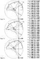
- FIGS. 18 to 20 describe centrically positioned screw profiles of the number of turns 3, according to the method for the production of tightly meshing, self-cleaning, co-rotating Screw profiles of the number of gears z are generated. In the FIGS. 18 to 20 always one sixth of a screw profile of the number 3 gear is shown.
- FIG. 18 The FIGS. 18a to 18d show preferred 2-circle screw profiles of a three-flighted screw profile.
- the FIGS. 18a to 18d differ by the worm outer radius RA.
- the radius R_1 of the 1st circular arc depends on the external screw radius RA.
- FIG. 19 The FIGS. 19a to 19d show preferred 4-circle screw profiles of a three-flighted screw profile.
- the FIGS. 19a to 19d differ by the worm outer radius RA.
- the angle ⁇ _1 of the 1st circular arc depends on the external screw radius RA.
- the radius ⁇ _2 of the second circular arc depends on the external screw radius RA.
- FIG. 20 The FIGS. 20a to 20d show further preferred 4-circle screw profiles of a three-flighted screw profile.
- the FIGS. 20a to 20d differ by the worm outer radius RA.
- the angle ⁇ _1 of the 1st circular arc depends on the external screw radius RA.
- the radius ⁇ _2 of the second circular arc depends on the external screw radius RA.
- FIGS. 18 to 20 One-sixth of three-flighted screw profiles consisting of a maximum of 4 circular arcs are shown. However, three-flighted screw profiles are by no means limited to 4 circular arcs. Rather, any number of circular arcs can be used to generate three-flighted screw profiles.
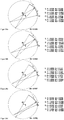
- FIG. 21 The Figures 21a to 21c show preferred embodiments of an eccentric positioning of three-flighted screw profiles.
- the FIG. 21a shows an eccentric positioning of a three-flighted screw profile FIG. 18c
- the FIG. 21b shows an eccentric positioning of a three-flighted screw profile FIG. 19c
- the FIG. 21c shows an eccentric positioning of a three-flighted screw profile FIG. 20c
- the other geometric parameters can be found in the individual figures.
- eccentric Positioned, three-flighted, tightly meshing, self-cleaning screw profiles are characterized by the fact that the minimum distance of the screw profiles to the housing is the same regardless of the direction of displacement for the left and right shaft.
- the three-flighted screw profiles in the Figures 21a to 21c are each positioned so eccentrically that each point of the comb portions of the sealing portion of the screw profiles touches the housing, so that a seal of the gusset portion is achieved.
- the eccentrically positioned three-flighted screw profile results in a screw profile with a sequence of sealing area - transition area - channel area - transition area. The seal thus takes place over two of the three crests of a three-flighted screw element.
- the three-flighted screw profiles are moved in the direction of one of their groove areas from the centric position. In the Figures 21a to 21c the displacement took place along the connecting line of the two pivot points of the screw profiles.
- FIG. 22 The FIGS. 22a to 22c show further preferred embodiments of an eccentric positioning of three-flighted screw profiles.
- the FIG. 22a shows an eccentric positioning of a three-flighted screw profile FIG. 18c
- the FIG. 22b shows an eccentric positioning of a three-flighted screw profile FIG. 19c
- the FIG. 22c shows an eccentric positioning of a three-flighted screw profile FIG. 20c
- the other geometric parameters can be found in the individual figures.
- the screw profiles in the FIGS. 22a to 22c are each positioned so eccentrically that only a point of a comb portion of the sealing portion of the screw profiles touches the housing. The size of the required shift depends on the direction of the shift.
- eccentric positioning of the screw profiles in which no point of the comb regions of the sealing region of the screw profiles touches the housing.
- the eccentric positioning of the screw profile of a screw element according to the invention enables the degree of a line-shaped or punctiform sealing of the gusset region to be adjusted.
- the mechanical and thermal stress of the viscous fluid in the region of the seal can thereby be adjusted in a targeted manner.
- the degree of sealing of the gusset portion in the comb portions may be adjusted depending on the direction of rotation of the screw members.
- the maximum distance of the comb regions of the sealing region of the screw profiles from the housing is preferably in the range of 0 to 0.05 times the center distance, particularly preferably in the range of 0 to 0.025 times the axial spacing.
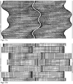
- FIG. 23a shows by way of example a pair of eccentric three-flighted conveying element following the screw profile FIG. 19c based.
- the length of the conveying elements is 1.2, which corresponds to a rotation of the screw profiles by an angle of 2 ⁇ .
- the housing is represented by thin, solid lines on the left and right of the two conveyor elements. On the surfaces of the two conveying elements, a possible computing grid is also shown, which can be used to calculate the flow in two- and multi-shaft extruders.
- FIG. 23b shows by way of example a pair of eccentric three-start kneading element following the screw profile FIG. 19c based.
- the kneading element consists of 7 kneading disks, which are each offset by an angle of ⁇ / 3 to each other right-handed.
- the first and last kneading discs have a length of 0.09.
- the medium kneading disks have a length of 0.18.
- the groove between the kneading discs has a length of 0.02.
- the housing is represented by thin, solid lines on the left and right of the two kneading elements. On the surfaces of the Both kneading elements also a possible computing grid is shown, which can be used to calculate the flow in two- and multi-shaft extruders.
- FIGS. 21 to 23 show eccentrically positioned three-flighted screw profiles and screw elements in which the dimensionless housing radius RG is equal to 0.63 and the virtual housing radius RV is equal to 0.5567.
- the eccentrically positioned three-flighted screw profiles of screw elements according to the invention and the method for producing screw profiles according to the invention are not limited to this discrete value of the housing radius or of the virtual housing radius.
- eccentrically positioned three-flighted screw profiles can be positioned in a housing with a radius RG in the range of 0.51 to 0.707, preferably in the range of 0.52 to 0.7, wherein the virtual housing radius with a radius RV in the range from 0.505 to 0.577, preferably in the range of 0.51 to 0.57.
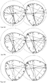
- the generating screw profile is represented by the left screw profile.
- the generated screw profile is represented by the right screw profile.
- Both screw profiles consist of 16 circular arcs.
- the circular arcs of the generating and the generated screw profile are characterized by thick, solid lines, which are provided with the respective numbers of circular arcs.
- the centers of the circular arcs are represented by small circles.
- the centers of the circular arcs are thin, solid lines with both the starting point and the End point of the associated circular arc connected.
- the external screw radius is approximately the same for the generating and the generated screw profile. In the area of the worm housing, the worm outer radius is characterized by a thin, dashed line, in the gusset area by a thin, dotted line.
- the FIG. 24a shows a pair of double-flighted screw profiles that start the transition.
- the generating and the generated screw profile are symmetrical to one another.
- the circular arcs 1 and 9 of the generating screw profile touch the worm outer radius over their entire length.
- the circular arcs 4, 5 and 12, 13 of the generating screw profile touch the core radius over their entire length.
- the arcs 4 ', 5' and 12 ', 13' of the generated screw profile touching the outer screw radius over its entire length.
- the circular arcs 1 'and 9' of the generated screw profile touching the core radius over their entire length.
- the FIG. 24f shows a pair of catchy screw profiles with which the transition ends.
- the generating and the generated screw profile are symmetrical to one another.
- the circular arcs 1 and 12 of the generating screw profile touch over its entire length the worm outer radius.
- the circular arcs 4 and 9 of the generating screw profile touch the core radius over their entire length.
- the circular arcs 4 'and 9' of the generated screw profile touch over its entire length the screw outer radius.
- the circular arcs 1 'and 12' of the generated screw profile touch the core radius over their entire length.
- the FIG. 24b shows a pair of transitional profiles in which the transition from the two-flighted screw profiles to the single-flighted screw profiles is 20% complete.
- the FIG. 24c shows a pair of transition profiles where the transition is 40% complete.
- the Figure 24d shows a pair of transition profiles where the transition is 60% complete.
- the FIG. 24e shows a pair of transition profiles where the transition is 80% complete.
- the transition takes place such that always the circular arc 1 of the generating screw profile touches the dimensionless outer screw radius RA over its entire length, whereby the associated circular arc 1 'of the generated screw profile touches the dimensionless core radius RI' over its entire length.
- the transition takes place such that always the circular arc 4 'of the generated screw profile touches the dimensionless outer screw radius RA', whereby the associated circular arc 4 of the generating screw profile touches the dimensionless core radius RI.
- a pair of transition elements always consists of a first transition element, which is based on the generating transition profiles, and a second transition element, which is based on the generated transition profiles.
- the method for producing flat, tightly meshing, self-cleaning, co-rotating screw profiles is not limited to this range of dimensionless outer screw radius.
- the circular arcs of the generating screw profile can be arranged clockwise or counterclockwise about the axis of rotation of the generating screw profile.
- the circular arcs are arranged counterclockwise about the axis of rotation of the generating screw profile.
- the position of the 1st arc of the generating screw profile is chosen so that the 1st arc lies within or on the boundaries of a circular ring with the dimensionless outer radius RA and the dimensionless inner radius RI whose center lies on the pivot point of the generating screw profile.
- the position is preferably determined by the positioning of the starting point and the center point of the 1st circular arc.
- the 1st circular arc lies on the worm outer radius RA and the arrangement rule that at least one circular arc touches the worm outer radius RA is fulfilled.
- the angles ⁇ _2, ..., ⁇ _ (n-1) of n-2 further circular arcs, ie 14 further circular arcs of the generating screw profile, are selected such that they are greater than or equal to 0 and less than or equal to 2 ⁇ in radians.
- the dimensionless radii R_2, ..., R_ (n-1) of these 14 further arcs of the generating screw profile become so is chosen to be greater than or equal to 0 and less than or equal to the dimensionless center distance A.
- the circular arcs are arranged so that the circular arcs merge tangentially into each other such that a closed, convex screw profile results, whereby a circular arc whose dimensionless radius is equal to 0 is treated like a circular arc whose dimensionless radius is equal to eps where eps is a very small positive real number that tends towards 0 (eps ⁇ 1, eps ⁇ 0). It follows from this ordering rule that the end point of a circular arc is equal to the starting point of its subsequent circular arc.
- the required tangential transition between a first circular arc and a second, subsequent circular arc is fulfilled by the fact that the center of this second, subsequent circular arc is placed on the straight line, which is given by the end point and the center of this first circular arc, that the distance of the center point of this second, subsequent circular arc from the end point of this first circular arc is equal to the radius of this second, subsequent circular arc and the screw profile is convex.
- a circular arc whose radius equals 0 is treated like a circular arc with a very small radius eps, where eps tends to 0, so that the tangential transition can still be constructed.
- a circular arc whose radius is 0 can be treated so that the screw profile has a kink at the position of this circular arc, the size of the kink being given by the angle of this circular arc.
- the generated screw profile results from the generating screw profile.
- the dimensionless outer screw radius RA 'of the generated screw profile is according to the invention equal to the difference of the dimensionless center distance A minus the dimensionless core radius RI of the generating screw profile.
- the dimensionless core radius RI 'of the generated screw profile is equal to the difference of the dimensionless center distance A minus the dimensionless outer screw radius RA of the generating screw profile.
- the angle ⁇ _i 'of the i'th arc of the generated screw profile is equal to the angle ⁇ _i of the i-th arc of the generating screw profile, where i and i' are integers that collectively represent all values in the range of 1 to the number of circular arcs n or n 'go through.
- FIG. 26 shows an eight-shaped screw housing with two holes.
- the area in which two housing bores penetrate is called the gusset area.
- the two intersections of two housing bores are referred to as housing gussets.
- the opening angle ⁇ _gz between the two housing gussets is shown.
- FIG. 27 shows the angles ⁇ _fb1, 8_fb2, ⁇ _nb1, ⁇ _nb2, ⁇ _kb1, ⁇ _kb2 and ⁇ _gb using a screw profile according to the invention.
- a maximum of 16 circular arcs are used to describe a generating or a generated screw profile.
- the methods are by no means limited to a maximum of 16 circular arcs. Rather, any number of circular arcs can be used to generate screw profiles. In particular, this makes it possible to approximate screw profiles that are not constructed from circular arcs and thus are not self-cleaning by a sufficiently high number of circular arcs with a desired accuracy.
- the longitudinal section profile can be calculated.
- each circular arc of a screw profile is used to calculate by means of an explicit function a part of the longitudinal section belonging to this circular arc.
- the intersection point (Sx, Sy) of a straight line g characterized in that the said straight line lies in the plane of the screw profile, passes through the pivot point of the screw profile in a first step and the orientation of the straight line is given by the angle ⁇ , with a circular arc kb, characterized by its radius r and the position of its center (Mx, My).
- the distance s of the point of intersection (Sx, Sy) is calculated from the point of rotation of the screw profile.
- the calculation of an intersection of a straight line with a circular arc can be represented by an explicit function. The same applies to the distance calculation.
- s s ( ⁇ , r, Mx, My).
- the function s (z_ax, r, Mx, My) describes the sought longitudinal section for a circular arc of the screw profile.
Landscapes
- Engineering & Computer Science (AREA)
- Mechanical Engineering (AREA)
- Physics & Mathematics (AREA)
- Algebra (AREA)
- General Physics & Mathematics (AREA)
- Mathematical Analysis (AREA)
- Mathematical Optimization (AREA)
- Mathematical Physics (AREA)
- Pure & Applied Mathematics (AREA)
- Extrusion Moulding Of Plastics Or The Like (AREA)
- Processing And Handling Of Plastics And Other Materials For Molding In General (AREA)
- Transmission Devices (AREA)
Claims (13)
- Eléments de vis sans fin avec des profils de vis sans fin engrenant étroitement, autonettoyants et tournant dans le même sens pour des machines à vis sans fin à plusieurs arbres de même sens par paires et se raclant exactement par paires, dans lesquels des profils de vis sans fin générateur et généré présentent une succession composée de: zone d'étanchéité - zone de transition - zone de canal - zone de transition, dans lesquels une zone d'étanchéité est une succession de zone d'engrènement- zone de flanc - zone d'engrènement, une zone de canal est une succession de zone de rainure - zone de flanc - zone de rainure et une zone de transition est une succession de zones de profils de vis sans fin, qui commence avec une zone de flanc et qui se termine avec une zone de flanc, caractérisés en ce que la zone d'étanchéité des éléments de vis sans fin est caractérisée en ce que∘ la zone de flanc possède, par rapport au centre de rotation du profil de vis sans fin, un angle δ_fb1, qui est supérieur ou égal à la moitié de l'angle d'ouverture entre les deux coins de boîtier, δ_fb1 ≥ arccos(0,5*a/ra), et qui est de préférence supérieur ou égal à l'angle d'ouverture entre les deux coins de boîtier δ_fb1 ≥ 2*arccos(0,5*a/ra), dans lequel ra est un rayon extérieur de vis sans fin et a est une distance axiale entre les axes de rotation des profils de vis sans fin générateur et généré,∘ une zone d'engrènement possède, par rapport au centre de rotation du profil de vis sans fin, un angle δ_kb1, qui est inférieur ou égal à la différence de l'angle d'engrènement d'un profil de vis sans fin d'Erdmenger à une entrée moins l'angle d'ouverture entre les deux coins de boîtier, δ_kb1 ≤ π-4*(arccos(0,5*a/ra), et qui est de préférence inférieur ou égal à l'angle d'engrènement d'un profil de vis sans fin d'Erdmenger à deux entrées, δ_kb1 ≤ π/2-2*arccos(0,5*a/ra),∘ l'autre zone d'engrènement possède, par rapport au centre de rotation du profil de vis sans fin, un angle δ_kb2, qui est inférieur ou égal à la différence de l'angle d'engrènement d'un profil de vis sans fin d'Erdmenger à une entrée moins l'angle d'ouverture entre les deux coins de boîtier, δ_kb2 ≤ π:-4*arccos(0,5*a/ra), et qui est de préférence inférieur ou égal à l'angle d'engrènement d'un profil de vis sans fin d'Erdmenger à deux entrées, δ_kb2 ≤ π/2-2*arccos(0,5*a/ra),et la zone de canal des éléments de vis sans fin est caractérisée en ce que∘ la zone de flanc possède, par rapport au centre de rotation du profil de vis sans fin, un angle δ_fb2, qui est supérieur ou égal à la moitié de l'angle d'ouverture entre les deux coins de boîtier, δ_fb2 ≥ arccos(0,5*a/ra), et qui est de préférence supérieur ou égal à l'angle d'ouverture entre les deux coins de boîtier, δ_fb2 ≥ 2*arccos(0,5*a/ra), et la distance minimale de la zone de flanc du rayon extérieur de vis sans fin ra est supérieure à la moitié de la profondeur de pas h,∘ une zone de rainure possède, par rapport au centre de rotation du profil de vis sans fin, un angle δ_nb1, qui est inférieur ou égal à la différence de l'angle d'engrènement d'un profil de vis sans fin d'Erdmenger à une entrée moins l'angle d'ouverture entre les deux coins de boîtier, δ_nb1 ≤ π-4*arccos(0,5*a/ra), et qui est de préférence inférieur ou égal à l'angle d'engrènement d'un profil de vis sans fin d'Erdmenger à deux entrées, δ_nb1 ≤ π/2-2*arccos(0,5*a/ra),∘ l'autre zone de rainure possède, par rapport au centre de rotation du profil de vis sans fin, un angle δ_nb2, qui est inférieur ou égal à la différence de l'angle d'engrènement d'un profil de vis sans fin d'Erdmenger à une entrée moins l'angle d'ouverture entre les deux coins de boîtier, δ_nb2 ≤ π:-4*arccos(0,5*a/ra), et qui est de préférence inférieur ou égal à l'angle d'engrènement d'un profil de vis sans fin d'Erdmenger à deux entrées, δ_nb2 ≤ π/2-2*arccos(0,5*a/ra).
- Eléments de vis sans fin selon la revendication 1, caractérisés en ce que la somme des angles des zones d'engrènement et de flanc δ_kb1, δ_kb2 et δ_fb1 de la zone d'étanchéité se situe de préférence dans la plage de 0,75*δ_gz à 2*δ_gb+δ_gz, et en particulier de préférence dans la plage de δ_gz à δ_gb+δ_gz, et la somme des angles des zones de rainure et de flanc δ_nb1, δ_nb2 et δ_fb2 de la zone de canal se situe de préférence dans la plage de 0,75*δ_gz à 2*δ_gb+δ_gz, et en particulier de préférence dans la plage de δ_gz à δ_gb+δ_gz.
- Eléments de vis sans fin selon la revendication 1 ou 2, caractérisés en ce que la zone de transition se compose d'une zone de flanc.
- Eléments de vis sans fin selon l'une quelconque des revendications 1 à 3, avec des profils de vis sans fin, qui assurent une étanchéité linéaire de la zone de coin.
- Eléments de vis sans fin selon l'une quelconque des revendications 1 à 3, avec des profils de vis sans fin qui assurent une étanchéité ponctuelle de la zone de coin.
- Eléments de vis sans fin selon l'une quelconque des revendications 1 à 5, caractérisés en ce que la distance maximale des zones d'engrènement de la zone d'étanchéité des profils de vis sans fin par rapport au boîtier se situe de préférence dans la plage de 0 à 0,05 fois la distance axiale, en particulier de préférence dans la plage de 0 à 0,025 fois la distance axiale.
- Eléments de vis sans fin selon l'une quelconque des revendications 1 à 6, avec un nombre de pas z = 1.
- Eléments de vis sans fin selon la revendication 7 avec 8 profils de vis sans fin circulaires.
- Eléments de vis sans fin selon l'une quelconque des revendications 1 à 6, avec un nombre de pas z = 3 et un positionnement excentrique.
- Eléments de vis sans fin selon l'une quelconque des revendications 1 à 9, caractérisés en ce qu'ils sont réalisés sous forme d'éléments de transport ou d'éléments de mélange.
- Eléments de vis sans fin selon l'une quelconque des revendications 1 à 9, caractérisés en ce qu'ils sont réalisés sous forme d'éléments de malaxage.
- Eléments de vis sans fin selon l'une quelconque des revendications 1 à 9, caractérisés en ce qu'ils sont réalisés sous forme d'éléments de transfert.
- Utilisation d'éléments de vis sans fin selon l'une quelconque des revendications 1 à 12 dans une machine à vis sans fin à plusieurs arbres.
Applications Claiming Priority (2)
| Application Number | Priority Date | Filing Date | Title |
|---|---|---|---|
| DE102008029306A DE102008029306A1 (de) | 2008-06-20 | 2008-06-20 | Schneckenelemente mit reduziertem Energieeintrag beim Druckaufbau |
| PCT/EP2009/004122 WO2009152974A2 (fr) | 2008-06-20 | 2009-06-09 | Éléments de vis sans fin à apport d'énergie réduit pendant la montée en pression |
Publications (2)
| Publication Number | Publication Date |
|---|---|
| EP2291279A2 EP2291279A2 (fr) | 2011-03-09 |
| EP2291279B1 true EP2291279B1 (fr) | 2018-07-18 |
Family
ID=41264296
Family Applications (2)
| Application Number | Title | Priority Date | Filing Date |
|---|---|---|---|
| EP09765527A Active EP2291278B1 (fr) | 2008-06-20 | 2009-05-30 | Procédé d'extrusion de masses plastiques |
| EP09765554.2A Active EP2291279B1 (fr) | 2008-06-20 | 2009-06-09 | Éléments de vis sans fin à apport d'énergie réduit pendant la montée en pression |
Family Applications Before (1)
| Application Number | Title | Priority Date | Filing Date |
|---|---|---|---|
| EP09765527A Active EP2291278B1 (fr) | 2008-06-20 | 2009-05-30 | Procédé d'extrusion de masses plastiques |
Country Status (15)
| Country | Link |
|---|---|
| US (2) | US9738025B2 (fr) |
| EP (2) | EP2291278B1 (fr) |
| JP (2) | JP5425898B2 (fr) |
| KR (1) | KR101575386B1 (fr) |
| CN (2) | CN102131627B (fr) |
| BR (1) | BRPI0914163A2 (fr) |
| CA (1) | CA2728442C (fr) |
| DE (1) | DE102008029306A1 (fr) |
| ES (2) | ES2392766T3 (fr) |
| HU (1) | HUE040172T2 (fr) |
| PL (1) | PL2291278T3 (fr) |
| RU (2) | RU2496643C9 (fr) |
| SG (1) | SG192413A1 (fr) |
| TW (1) | TWI556940B (fr) |
| WO (2) | WO2009152947A2 (fr) |
Families Citing this family (30)
| Publication number | Priority date | Publication date | Assignee | Title |
|---|---|---|---|---|
| JP3868757B2 (ja) * | 2001-04-25 | 2007-01-17 | 株式会社神戸製鋼所 | ゴム系組成物の混練装置および混練方法 |
| WO2010061615A1 (fr) * | 2008-11-28 | 2010-06-03 | 住友化学株式会社 | Procédé de production de substrat semi-conducteur, substrat semi-conducteur, procédé de fabrication de dispositif électronique et appareil de réaction |
| KR20110097755A (ko) * | 2008-11-28 | 2011-08-31 | 스미또모 가가꾸 가부시키가이샤 | 반도체 기판의 제조 방법, 반도체 기판, 전자 디바이스의 제조 방법, 및 반응 장치 |
| US8823141B2 (en) | 2009-03-11 | 2014-09-02 | Sumitomo Chemical Company, Limited | Semiconductor wafer, method of producing semiconductor wafer, electronic device, and method of producing electronic device |
| KR20120022872A (ko) | 2009-05-22 | 2012-03-12 | 스미또모 가가꾸 가부시키가이샤 | 반도체 기판, 전자 디바이스, 반도체 기판의 제조 방법 및 전자 디바이스의 제조 방법 |
| EP2256146A1 (fr) | 2009-05-30 | 2010-12-01 | Bayer MaterialScience AG | Polycarbonate doté d'une pureté extrêmement élevée, d'une couleur propre correcte et d'une résistance thermique ainsi que dispositif et procédé destinés à sa fabrication |
| EP2255860A1 (fr) | 2009-05-30 | 2010-12-01 | Bayer MaterialScience AG | Dispositif et procédé de dégazage de solutions de polycarbonate contenant des solvants |
| EP2255859A1 (fr) | 2009-05-30 | 2010-12-01 | Bayer MaterialScience AG | Dispositif et procédé de dégazage de solutions de polycarbonate contenant une solution |
| CN102449775B (zh) | 2009-06-05 | 2014-07-02 | 独立行政法人产业技术综合研究所 | 半导体基板、光电转换器件、半导体基板的制造方法和光电转换器件的制造方法 |
| WO2010140370A1 (fr) | 2009-06-05 | 2010-12-09 | 住友化学株式会社 | Dispositif optique, substrat semiconducteur, procede de production de dispositif optique et procede de production de substrat semiconducteur |
| WO2010140373A1 (fr) | 2009-06-05 | 2010-12-09 | 住友化学株式会社 | Capteur, substrat semi-conducteur et procédé de fabrication de substrat semi-conducteur |
| JP5318709B2 (ja) * | 2009-08-26 | 2013-10-16 | ポリプラスチックス株式会社 | スクリューエレメントピース及びスクリュー |
| DE102009040047A1 (de) | 2009-09-04 | 2011-03-17 | Bayer Materialscience Ag | Verfahren zur Einarbeitung von Feststoffen in Polymere |
| EP2547719B1 (fr) * | 2010-03-17 | 2014-04-30 | Evonik Röhm GmbH | Pellicules de grande qualité optique résistant aux produits chimiques |
| EP2747980B1 (fr) | 2012-02-28 | 2016-07-20 | Steer Engineering Private Limited | Élément de mélange d'extrusion |
| AT512974B1 (de) | 2012-05-23 | 2015-02-15 | Josef A Ing Blach | Mehrwellenextruder |
| EP3013551B1 (fr) * | 2013-06-24 | 2018-03-21 | Covestro Deutschland AG | Éléments de vis pour les machines multi-vis et leur procédé de fabrication |
| KR102360072B1 (ko) | 2014-12-08 | 2022-02-08 | 삼성전자주식회사 | 미세입자 분리 장치 |
| CN104527025B (zh) * | 2014-12-29 | 2017-05-17 | 广东轻工职业技术学院 | 带有折流板的同向自洁双螺杆挤出机及其加工方法 |
| CN105058743B (zh) * | 2015-07-24 | 2018-06-26 | 广东轻工职业技术学院 | 头数渐变全程自洁的同向自洁双螺杆挤出机及其加工方法 |
| CN105690688A (zh) * | 2016-03-16 | 2016-06-22 | 华南理工大学 | 一种双轴或三轴偏心转子体积脉动形变塑化加工方法及设备 |
| CN107139424B (zh) * | 2017-07-07 | 2023-07-21 | 中国石油大学(华东) | 一种全光滑的双螺杆挤出机螺杆转子 |
| WO2019070797A1 (fr) | 2017-10-05 | 2019-04-11 | Corning Incorporated | Éléments de vis pour appareil d'extrusion et procédés de fabrication d'un corps en nid d'abeilles |
| US11571832B2 (en) * | 2017-10-05 | 2023-02-07 | Corning Incorporated | Kneading elements for extrusion apparatus and methods of manufacturing a honeycomb body |
| US11169192B2 (en) * | 2018-04-23 | 2021-11-09 | The Government Of The United States, As Represented By The Secretary Of The Army | Trigonometry dependent plot creation |
| JP2022522138A (ja) * | 2019-02-27 | 2022-04-14 | コベストロ・インテレクチュアル・プロパティ・ゲゼルシャフト・ミット・ベシュレンクテル・ハフツング・アンド・コー・カーゲー | 軸方向に非対称なスクリュー輪郭内に少なくとも2個の作図点を有するスクリュー輪郭を有するスクリュー要素 |
| FR3093457A1 (fr) * | 2019-03-06 | 2020-09-11 | Compagnie Generale Des Etablissements Michelin | Machine de Mélangeage et d’Extrusion à Bi-Vis avec Éléments Amovibles |
| EP4232259B1 (fr) * | 2020-10-22 | 2025-07-09 | Covestro Deutschland AG | Extrudeuse comprenant un système spécial d'éléments à vis sans fin asymétriques sur les arbres de vis sans fin |
| JP7075707B1 (ja) | 2021-12-28 | 2022-05-26 | 株式会社Steer Japan | 溶融混練押出装置の運転の際に必要なエネルギーを低減可能とする方法 |
| DE202023105394U1 (de) * | 2023-09-17 | 2024-12-20 | VEKA Aktiengesellschaft | Ressourcenschonendes Doppelschneckenextruder-System mit mehreren Doppelschneckenextrudern für die Kunststoffverarbeitung |
Family Cites Families (41)
| Publication number | Priority date | Publication date | Assignee | Title |
|---|---|---|---|---|
| DE862668C (de) | 1944-07-07 | 1953-01-12 | Bayer Ag | Vorrichtung zum Verkneten, Gelatinieren und Verpressen von plastischen Massen |
| US2670188A (en) * | 1949-09-23 | 1954-02-23 | Bayer Ag | Mixing and kneading machine |
| DE813154C (de) | 1949-09-29 | 1951-09-06 | Bayer Ag | Misch- und Knetvorrichtung |
| US3122356A (en) * | 1958-08-23 | 1964-02-25 | Bayer Ag | Worm arrangement |
| US3146493A (en) * | 1960-07-25 | 1964-09-01 | Bergwerksgesellschaft Hibernia | Process and apparatus for the production of polyolefine granulates |
| DE1180718B (de) | 1962-04-11 | 1964-11-05 | Bayer Ag | Knetvorrichtung mit zwei oder mehr Schnecken |
| NL152889B (nl) | 1967-03-10 | 1977-04-15 | Gen Electric | Werkwijze ter bereiding van een lineair polycarbonaatcopolymeer, alsmede orienteerbare textielvezel van dit copolymeer. |
| DE1679884B2 (de) * | 1967-12-16 | 1971-08-26 | Werner & Pfleiderer | Mehrwellige kontinuierlich arbeitende misch und knetmaschine fuer plastizierbare massen |
| CA1036744A (fr) * | 1973-03-30 | 1978-08-15 | Heinrich Haupt | Mode de preparation de polycarbonates aromatiques auxquels on substitue un halogene |
| US3900187A (en) * | 1973-10-29 | 1975-08-19 | Baker Perkins Inc | Continuous mixing and/or kneading machine with co-wiping single lead screws |
| DE2653143C2 (de) * | 1976-11-23 | 1985-01-31 | Bayer Ag, 5090 Leverkusen | Thermoplastische Formmassen |
| US4131371A (en) | 1977-08-03 | 1978-12-26 | E. I. Du Pont De Nemours And Company | Co-rotating multiple screw processor |
| JPS5829733B2 (ja) * | 1977-11-19 | 1983-06-24 | 積水化学工業株式会社 | 押出機 |
| DE3206325C2 (de) * | 1982-02-22 | 1985-10-10 | AUTOMATIK Apparate-Maschinenbau GmbH, 8754 Großostheim | Mehrwellige, kontinuierlich arbeitende Misch- und Knetmaschine für plastifizierbare Massen |
| DE3412258A1 (de) | 1984-04-02 | 1985-10-10 | Werner & Pfleiderer, 7000 Stuttgart | Gleichdrall-doppelschneckenkneter mit knetscheiben |
| NO170326C (no) | 1988-08-12 | 1992-10-07 | Bayer Ag | Dihydroksydifenylcykloalkaner |
| DE3844633A1 (de) | 1988-08-12 | 1990-04-19 | Bayer Ag | Dihydroxydiphenylcycloalkane, ihre herstellung und ihre verwendung zur herstellung von hochmolekularen polycarbonaten |
| US5227458A (en) | 1988-08-12 | 1993-07-13 | Bayer Aktiengesellschaft | Polycarbonate from dihydroxydiphenyl cycloalkane |
| DE4239220C2 (de) | 1992-11-21 | 1996-08-22 | Blach Verfahrenstechnik Gmbh | Gleichdrall - Doppelschneckenextruder |
| US5573332A (en) * | 1993-09-02 | 1996-11-12 | Werner & Pfleiderer Gmbh | Screw element for a screw-like extrusion machine |
| US5487602A (en) * | 1994-06-03 | 1996-01-30 | Farrel Corporation | Multi-screw, extrusion-compounding machine with modular mixing elements |
| AU1958497A (en) * | 1996-02-21 | 1997-09-10 | Extruder Vitrification Group, L.L.C. | Vitrification of nuclear and other toxic wastes |
| DE19718292A1 (de) * | 1997-04-30 | 1998-11-05 | Krupp Werner & Pfleiderer Gmbh | Mehrwellen-Schneckenmaschine, insbesondere Zwei-Wellen-Extruder |
| EP1121238B1 (fr) * | 1998-10-05 | 2002-05-15 | Coperion Werner & Pfleiderer GmbH & Co. KG | Extrudeuse a deux vis a rotation identique |
| DE19860256A1 (de) * | 1998-12-24 | 2000-06-29 | Krupp Werner & Pfleiderer Gmbh | Zwei-Wellen-Extruder |
| DE19950917A1 (de) * | 1999-10-21 | 2001-04-26 | Degussa | Doppelschneckenextruder mit neuen Schneckenelementen |
| JP3798595B2 (ja) * | 2000-01-25 | 2006-07-19 | 株式会社神戸製鋼所 | 混練用ロータ、スクリューセット及び2軸押出機 |
| US6974620B1 (en) * | 2000-02-28 | 2005-12-13 | Toray Industries, Inc. | Polyester film for heat-resistant capacitor, metallized film thereof, and heat-resistant film capacitor containing the same |
| IT1319996B1 (it) * | 2000-03-23 | 2003-11-12 | Maris Flli Spa | Elemento di miscelazione per vite di estrusore bivite corotante edestrusore che lo comprende. |
| US6783270B1 (en) * | 2000-07-31 | 2004-08-31 | Steer Engineering (P) Limited | Fractional and higher lobed co-rotating twin-screw elements |
| JP4297601B2 (ja) * | 2000-09-13 | 2009-07-15 | 株式会社日本製鋼所 | 同方向回転二軸押出機 |
| DE10057164A1 (de) * | 2000-11-16 | 2002-05-23 | Basf Ag | Pigmentzubereitungen |
| DE10114727B4 (de) * | 2001-03-22 | 2005-05-12 | Berstorff Gmbh | Schneckenelement für gleichsinnig drehende Mehrschneckenextruder |
| US7015299B2 (en) * | 2001-04-30 | 2006-03-21 | Wilkinson W Kenneth | Melt spun thermoplastic polyurethanes useful as textile fibers |
| DE10149765B4 (de) * | 2001-10-02 | 2004-03-18 | Krauss-Maffei Kunststofftechnik Gmbh | Kämmelement |
| EP1316399B1 (fr) * | 2001-11-29 | 2010-10-06 | Kabushiki Kaisha Kobe Seiko Sho (Kobe Steel, Ltd.) | Appareil de pétrissage |
| US7188992B2 (en) * | 2003-07-30 | 2007-03-13 | Americhem, Inc. | Kneading element and related articles |
| DE50312862D1 (de) * | 2003-08-22 | 2010-08-19 | Coperion Gmbh | Schneckenmaschine mit Misch- und Knet-Scheiben |
| JP4613508B2 (ja) * | 2004-04-06 | 2011-01-19 | 横浜ゴム株式会社 | 酸素吸収剤を含む空気入りタイヤ |
| US8344058B2 (en) * | 2005-08-26 | 2013-01-01 | CID Centro de Investigación y Desarrollo Technológico S.A. de C.V. | Reactive block copolymers as additives for the preparation of silicate-polymer composites |
| US7759456B2 (en) * | 2006-06-30 | 2010-07-20 | Sabic Innovative Plastics Ip B.V. | Branched polycarbonate resins and processes to prepare the same |
-
2008
- 2008-06-20 DE DE102008029306A patent/DE102008029306A1/de not_active Withdrawn
-
2009
- 2009-05-30 EP EP09765527A patent/EP2291278B1/fr active Active
- 2009-05-30 KR KR1020107028466A patent/KR101575386B1/ko not_active Expired - Fee Related
- 2009-05-30 ES ES09765527T patent/ES2392766T3/es active Active
- 2009-05-30 SG SG2013047246A patent/SG192413A1/en unknown
- 2009-05-30 US US13/000,057 patent/US9738025B2/en active Active
- 2009-05-30 CN CN200980123344.9A patent/CN102131627B/zh active Active
- 2009-05-30 JP JP2011513902A patent/JP5425898B2/ja not_active Expired - Fee Related
- 2009-05-30 WO PCT/EP2009/003889 patent/WO2009152947A2/fr not_active Ceased
- 2009-05-30 RU RU2011101761/05A patent/RU2496643C9/ru not_active IP Right Cessation
- 2009-05-30 PL PL09765527T patent/PL2291278T3/pl unknown
- 2009-06-09 BR BRPI0914163A patent/BRPI0914163A2/pt not_active IP Right Cessation
- 2009-06-09 JP JP2011513915A patent/JP5508406B2/ja not_active Expired - Fee Related
- 2009-06-09 EP EP09765554.2A patent/EP2291279B1/fr active Active
- 2009-06-09 CA CA2728442A patent/CA2728442C/fr not_active Expired - Fee Related
- 2009-06-09 US US12/999,409 patent/US9808978B2/en active Active
- 2009-06-09 RU RU2011101760/05A patent/RU2516552C9/ru not_active IP Right Cessation
- 2009-06-09 CN CN200980123151.3A patent/CN102333635B/zh active Active
- 2009-06-09 ES ES09765554.2T patent/ES2691402T3/es active Active
- 2009-06-09 WO PCT/EP2009/004122 patent/WO2009152974A2/fr not_active Ceased
- 2009-06-09 HU HUE09765554A patent/HUE040172T2/hu unknown
- 2009-06-19 TW TW098120531A patent/TWI556940B/zh not_active IP Right Cessation
Non-Patent Citations (1)
| Title |
|---|
| None * |
Also Published As
Similar Documents
| Publication | Publication Date | Title |
|---|---|---|
| EP2291279B1 (fr) | Éléments de vis sans fin à apport d'énergie réduit pendant la montée en pression | |
| EP2291277B1 (fr) | Procédé pour la construction de corps corotatifs entrant en contact les uns avec les autres, progiciel pour la mise en oeuvre de ce procédé | |
| EP2303531B1 (fr) | Éléments de vis sans fin à effet dispersant amélioré et à apport d'énergie réduit | |
| EP2291270B1 (fr) | Éléments de vis sans fin à angle de filet réduit | |
| EP2550141B1 (fr) | Extrudeuse | |
| EP2512776B1 (fr) | Modèles basés sur des données pour le pronostic et l'optimisation d'extrudeuses à vis et/ou de procédés d'extrusion | |
| EP2509765B1 (fr) | Procédé de construction de corps corotatifs entrant en contact | |
| EP2852485A1 (fr) | Extrudeuse à plusieurs vis munie d'une vis de refoulement autonettoyante | |
| EP3013551B1 (fr) | Éléments de vis pour les machines multi-vis et leur procédé de fabrication | |
| EP2335898B1 (fr) | Extrudeuse planétaire | |
| EP0054186B1 (fr) | Dispositif pour mélanger, disperser et homogénéiser des masses ayant au moins un composant visqueux | |
| DE10114727B4 (de) | Schneckenelement für gleichsinnig drehende Mehrschneckenextruder | |
| EP3930983B1 (fr) | Élément à vis sans fin à profil de vis sans fin non axisymétrique et son utilisation | |
| DE2611908C2 (de) | Mehrwellige Schneckenmaschine | |
| EP4635712A1 (fr) | Dispositif d'arbre d'extrudeuse pour une extrudeuse à deux arbres contrarotatives | |
| DE2317617C3 (de) | Mehrschneckenextruder zum Plastizieren von thermoplastischen Kunststoffen | |
| DE2317617B2 (de) | Mehrschneckenextruder zum plastizieren von thermoplastischen kunststoffen |
Legal Events
| Date | Code | Title | Description |
|---|---|---|---|
| PUAI | Public reference made under article 153(3) epc to a published international application that has entered the european phase |
Free format text: ORIGINAL CODE: 0009012 |
|
| AK | Designated contracting states |
Kind code of ref document: A2 Designated state(s): AT BE BG CH CY CZ DE DK EE ES FI FR GB GR HR HU IE IS IT LI LT LU LV MC MK MT NL NO PL PT RO SE SI SK TR |
|
| AX | Request for extension of the european patent |
Extension state: AL BA RS |
|
| R17D | Deferred search report published (corrected) |
Effective date: 20110310 |
|
| 17P | Request for examination filed |
Effective date: 20110912 |
|
| RBV | Designated contracting states (corrected) |
Designated state(s): AT BE BG CH CY CZ DE DK EE ES FI FR GB GR HR HU IE IS IT LI LT LU LV MC MK MT NL NO PL PT RO SE SI SK TR |
|
| DAX | Request for extension of the european patent (deleted) | ||
| RAP1 | Party data changed (applicant data changed or rights of an application transferred) |
Owner name: BAYER INTELLECTUAL PROPERTY GMBH |
|
| RAP1 | Party data changed (applicant data changed or rights of an application transferred) |
Owner name: COVESTRO DEUTSCHLAND AG |
|
| REG | Reference to a national code |
Ref country code: DE Ref legal event code: R079 Ref document number: 502009015100 Country of ref document: DE Free format text: PREVIOUS MAIN CLASS: B29C0047400000 Ipc: B29C0047640000 |
|
| GRAP | Despatch of communication of intention to grant a patent |
Free format text: ORIGINAL CODE: EPIDOSNIGR1 |
|
| STAA | Information on the status of an ep patent application or granted ep patent |
Free format text: STATUS: GRANT OF PATENT IS INTENDED |
|
| RIC1 | Information provided on ipc code assigned before grant |
Ipc: B29C 47/38 20060101ALI20171205BHEP Ipc: B29C 47/60 20060101ALI20171205BHEP Ipc: B29C 47/40 20060101ALI20171205BHEP Ipc: B29C 47/62 20060101ALI20171205BHEP Ipc: B29C 47/64 20060101AFI20171205BHEP Ipc: B29B 7/48 20060101ALI20171205BHEP |
|
| INTG | Intention to grant announced |
Effective date: 20171221 |
|
| GRAJ | Information related to disapproval of communication of intention to grant by the applicant or resumption of examination proceedings by the epo deleted |
Free format text: ORIGINAL CODE: EPIDOSDIGR1 |
|
| STAA | Information on the status of an ep patent application or granted ep patent |
Free format text: STATUS: REQUEST FOR EXAMINATION WAS MADE |
|
| GRAP | Despatch of communication of intention to grant a patent |
Free format text: ORIGINAL CODE: EPIDOSNIGR1 |
|
| STAA | Information on the status of an ep patent application or granted ep patent |
Free format text: STATUS: GRANT OF PATENT IS INTENDED |
|
| INTG | Intention to grant announced |
Effective date: 20180131 |
|
| GRAS | Grant fee paid |
Free format text: ORIGINAL CODE: EPIDOSNIGR3 |
|
| GRAA | (expected) grant |
Free format text: ORIGINAL CODE: 0009210 |
|
| STAA | Information on the status of an ep patent application or granted ep patent |
Free format text: STATUS: THE PATENT HAS BEEN GRANTED |
|
| AK | Designated contracting states |
Kind code of ref document: B1 Designated state(s): AT BE BG CH CY CZ DE DK EE ES FI FR GB GR HR HU IE IS IT LI LT LU LV MC MK MT NL NO PL PT RO SE SI SK TR |
|
| REG | Reference to a national code |
Ref country code: GB Ref legal event code: FG4D Free format text: NOT ENGLISH |
|
| REG | Reference to a national code |
Ref country code: CH Ref legal event code: EP |
|
| REG | Reference to a national code |
Ref country code: IE Ref legal event code: FG4D Free format text: LANGUAGE OF EP DOCUMENT: GERMAN |
|
| REG | Reference to a national code |
Ref country code: AT Ref legal event code: REF Ref document number: 1018879 Country of ref document: AT Kind code of ref document: T Effective date: 20180815 |
|
| REG | Reference to a national code |
Ref country code: DE Ref legal event code: R096 Ref document number: 502009015100 Country of ref document: DE |
|
| REG | Reference to a national code |
Ref country code: NL Ref legal event code: FP |
|
| REG | Reference to a national code |
Ref country code: ES Ref legal event code: FG2A Ref document number: 2691402 Country of ref document: ES Kind code of ref document: T3 Effective date: 20181127 Ref country code: DE Ref legal event code: R079 Ref document number: 502009015100 Country of ref document: DE Free format text: PREVIOUS MAIN CLASS: B29C0047640000 Ipc: B29C0048670000 |
|
| REG | Reference to a national code |
Ref country code: LT Ref legal event code: MG4D |
|
| PG25 | Lapsed in a contracting state [announced via postgrant information from national office to epo] |
Ref country code: FI Free format text: LAPSE BECAUSE OF FAILURE TO SUBMIT A TRANSLATION OF THE DESCRIPTION OR TO PAY THE FEE WITHIN THE PRESCRIBED TIME-LIMIT Effective date: 20180718 Ref country code: IS Free format text: LAPSE BECAUSE OF FAILURE TO SUBMIT A TRANSLATION OF THE DESCRIPTION OR TO PAY THE FEE WITHIN THE PRESCRIBED TIME-LIMIT Effective date: 20181118 Ref country code: NO Free format text: LAPSE BECAUSE OF FAILURE TO SUBMIT A TRANSLATION OF THE DESCRIPTION OR TO PAY THE FEE WITHIN THE PRESCRIBED TIME-LIMIT Effective date: 20181018 Ref country code: GR Free format text: LAPSE BECAUSE OF FAILURE TO SUBMIT A TRANSLATION OF THE DESCRIPTION OR TO PAY THE FEE WITHIN THE PRESCRIBED TIME-LIMIT Effective date: 20181019 Ref country code: BG Free format text: LAPSE BECAUSE OF FAILURE TO SUBMIT A TRANSLATION OF THE DESCRIPTION OR TO PAY THE FEE WITHIN THE PRESCRIBED TIME-LIMIT Effective date: 20181018 Ref country code: SE Free format text: LAPSE BECAUSE OF FAILURE TO SUBMIT A TRANSLATION OF THE DESCRIPTION OR TO PAY THE FEE WITHIN THE PRESCRIBED TIME-LIMIT Effective date: 20180718 Ref country code: LT Free format text: LAPSE BECAUSE OF FAILURE TO SUBMIT A TRANSLATION OF THE DESCRIPTION OR TO PAY THE FEE WITHIN THE PRESCRIBED TIME-LIMIT Effective date: 20180718 Ref country code: PL Free format text: LAPSE BECAUSE OF FAILURE TO SUBMIT A TRANSLATION OF THE DESCRIPTION OR TO PAY THE FEE WITHIN THE PRESCRIBED TIME-LIMIT Effective date: 20180718 |
|
| PG25 | Lapsed in a contracting state [announced via postgrant information from national office to epo] |
Ref country code: HR Free format text: LAPSE BECAUSE OF FAILURE TO SUBMIT A TRANSLATION OF THE DESCRIPTION OR TO PAY THE FEE WITHIN THE PRESCRIBED TIME-LIMIT Effective date: 20180718 Ref country code: LV Free format text: LAPSE BECAUSE OF FAILURE TO SUBMIT A TRANSLATION OF THE DESCRIPTION OR TO PAY THE FEE WITHIN THE PRESCRIBED TIME-LIMIT Effective date: 20180718 |
|
| REG | Reference to a national code |
Ref country code: HU Ref legal event code: AG4A Ref document number: E040172 Country of ref document: HU |
|
| REG | Reference to a national code |
Ref country code: DE Ref legal event code: R097 Ref document number: 502009015100 Country of ref document: DE |
|
| PG25 | Lapsed in a contracting state [announced via postgrant information from national office to epo] |
Ref country code: RO Free format text: LAPSE BECAUSE OF FAILURE TO SUBMIT A TRANSLATION OF THE DESCRIPTION OR TO PAY THE FEE WITHIN THE PRESCRIBED TIME-LIMIT Effective date: 20180718 Ref country code: EE Free format text: LAPSE BECAUSE OF FAILURE TO SUBMIT A TRANSLATION OF THE DESCRIPTION OR TO PAY THE FEE WITHIN THE PRESCRIBED TIME-LIMIT Effective date: 20180718 |
|
| PLBE | No opposition filed within time limit |
Free format text: ORIGINAL CODE: 0009261 |
|
| STAA | Information on the status of an ep patent application or granted ep patent |
Free format text: STATUS: NO OPPOSITION FILED WITHIN TIME LIMIT |
|
| PG25 | Lapsed in a contracting state [announced via postgrant information from national office to epo] |
Ref country code: DK Free format text: LAPSE BECAUSE OF FAILURE TO SUBMIT A TRANSLATION OF THE DESCRIPTION OR TO PAY THE FEE WITHIN THE PRESCRIBED TIME-LIMIT Effective date: 20180718 Ref country code: SK Free format text: LAPSE BECAUSE OF FAILURE TO SUBMIT A TRANSLATION OF THE DESCRIPTION OR TO PAY THE FEE WITHIN THE PRESCRIBED TIME-LIMIT Effective date: 20180718 |
|
| 26N | No opposition filed |
Effective date: 20190423 |
|
| PG25 | Lapsed in a contracting state [announced via postgrant information from national office to epo] |
Ref country code: SI Free format text: LAPSE BECAUSE OF FAILURE TO SUBMIT A TRANSLATION OF THE DESCRIPTION OR TO PAY THE FEE WITHIN THE PRESCRIBED TIME-LIMIT Effective date: 20180718 |
|
| PG25 | Lapsed in a contracting state [announced via postgrant information from national office to epo] |
Ref country code: MC Free format text: LAPSE BECAUSE OF FAILURE TO SUBMIT A TRANSLATION OF THE DESCRIPTION OR TO PAY THE FEE WITHIN THE PRESCRIBED TIME-LIMIT Effective date: 20180718 |
|
| PG25 | Lapsed in a contracting state [announced via postgrant information from national office to epo] |
Ref country code: TR Free format text: LAPSE BECAUSE OF FAILURE TO SUBMIT A TRANSLATION OF THE DESCRIPTION OR TO PAY THE FEE WITHIN THE PRESCRIBED TIME-LIMIT Effective date: 20180718 |
|
| PG25 | Lapsed in a contracting state [announced via postgrant information from national office to epo] |
Ref country code: IE Free format text: LAPSE BECAUSE OF NON-PAYMENT OF DUE FEES Effective date: 20190609 |
|
| PG25 | Lapsed in a contracting state [announced via postgrant information from national office to epo] |
Ref country code: LU Free format text: LAPSE BECAUSE OF NON-PAYMENT OF DUE FEES Effective date: 20190609 |
|
| PG25 | Lapsed in a contracting state [announced via postgrant information from national office to epo] |
Ref country code: PT Free format text: LAPSE BECAUSE OF FAILURE TO SUBMIT A TRANSLATION OF THE DESCRIPTION OR TO PAY THE FEE WITHIN THE PRESCRIBED TIME-LIMIT Effective date: 20181118 |
|
| PGFP | Annual fee paid to national office [announced via postgrant information from national office to epo] |
Ref country code: FR Payment date: 20200526 Year of fee payment: 12 Ref country code: CZ Payment date: 20200529 Year of fee payment: 12 |
|
| PGFP | Annual fee paid to national office [announced via postgrant information from national office to epo] |
Ref country code: GB Payment date: 20200527 Year of fee payment: 12 Ref country code: HU Payment date: 20200601 Year of fee payment: 12 |
|
| PGFP | Annual fee paid to national office [announced via postgrant information from national office to epo] |
Ref country code: AT Payment date: 20200526 Year of fee payment: 12 |
|
| PG25 | Lapsed in a contracting state [announced via postgrant information from national office to epo] |
Ref country code: CY Free format text: LAPSE BECAUSE OF FAILURE TO SUBMIT A TRANSLATION OF THE DESCRIPTION OR TO PAY THE FEE WITHIN THE PRESCRIBED TIME-LIMIT Effective date: 20180718 |
|
| PG25 | Lapsed in a contracting state [announced via postgrant information from national office to epo] |
Ref country code: MT Free format text: LAPSE BECAUSE OF FAILURE TO SUBMIT A TRANSLATION OF THE DESCRIPTION OR TO PAY THE FEE WITHIN THE PRESCRIBED TIME-LIMIT Effective date: 20180718 |
|
| PG25 | Lapsed in a contracting state [announced via postgrant information from national office to epo] |
Ref country code: CZ Free format text: LAPSE BECAUSE OF NON-PAYMENT OF DUE FEES Effective date: 20210609 |
|
| REG | Reference to a national code |
Ref country code: AT Ref legal event code: MM01 Ref document number: 1018879 Country of ref document: AT Kind code of ref document: T Effective date: 20210609 |
|
| GBPC | Gb: european patent ceased through non-payment of renewal fee |
Effective date: 20210609 |
|
| PG25 | Lapsed in a contracting state [announced via postgrant information from national office to epo] |
Ref country code: HU Free format text: LAPSE BECAUSE OF NON-PAYMENT OF DUE FEES Effective date: 20210610 Ref country code: GB Free format text: LAPSE BECAUSE OF NON-PAYMENT OF DUE FEES Effective date: 20210609 Ref country code: AT Free format text: LAPSE BECAUSE OF NON-PAYMENT OF DUE FEES Effective date: 20210609 |
|
| PG25 | Lapsed in a contracting state [announced via postgrant information from national office to epo] |
Ref country code: FR Free format text: LAPSE BECAUSE OF NON-PAYMENT OF DUE FEES Effective date: 20210630 |
|
| PG25 | Lapsed in a contracting state [announced via postgrant information from national office to epo] |
Ref country code: MK Free format text: LAPSE BECAUSE OF FAILURE TO SUBMIT A TRANSLATION OF THE DESCRIPTION OR TO PAY THE FEE WITHIN THE PRESCRIBED TIME-LIMIT Effective date: 20180718 |
|
| PGFP | Annual fee paid to national office [announced via postgrant information from national office to epo] |
Ref country code: BE Payment date: 20220526 Year of fee payment: 14 |
|
| PGFP | Annual fee paid to national office [announced via postgrant information from national office to epo] |
Ref country code: ES Payment date: 20220705 Year of fee payment: 14 |
|
| PGFP | Annual fee paid to national office [announced via postgrant information from national office to epo] |
Ref country code: CH Payment date: 20220702 Year of fee payment: 14 |
|
| REG | Reference to a national code |
Ref country code: CH Ref legal event code: PL |
|
| REG | Reference to a national code |
Ref country code: BE Ref legal event code: MM Effective date: 20230630 |
|
| PG25 | Lapsed in a contracting state [announced via postgrant information from national office to epo] |
Ref country code: CH Free format text: LAPSE BECAUSE OF NON-PAYMENT OF DUE FEES Effective date: 20230630 |
|
| PG25 | Lapsed in a contracting state [announced via postgrant information from national office to epo] |
Ref country code: BE Free format text: LAPSE BECAUSE OF NON-PAYMENT OF DUE FEES Effective date: 20230630 |
|
| REG | Reference to a national code |
Ref country code: ES Ref legal event code: FD2A Effective date: 20240729 |
|
| PG25 | Lapsed in a contracting state [announced via postgrant information from national office to epo] |
Ref country code: ES Free format text: LAPSE BECAUSE OF NON-PAYMENT OF DUE FEES Effective date: 20230610 |
|
| PG25 | Lapsed in a contracting state [announced via postgrant information from national office to epo] |
Ref country code: ES Free format text: LAPSE BECAUSE OF NON-PAYMENT OF DUE FEES Effective date: 20230610 |
|
| PGFP | Annual fee paid to national office [announced via postgrant information from national office to epo] |
Ref country code: NL Payment date: 20250526 Year of fee payment: 17 |
|
| PGFP | Annual fee paid to national office [announced via postgrant information from national office to epo] |
Ref country code: DE Payment date: 20250521 Year of fee payment: 17 |
|
| PGFP | Annual fee paid to national office [announced via postgrant information from national office to epo] |
Ref country code: IT Payment date: 20250528 Year of fee payment: 17 |