EP1121238B1 - Extrudeuse a deux vis a rotation identique - Google Patents
Extrudeuse a deux vis a rotation identique Download PDFInfo
- Publication number
- EP1121238B1 EP1121238B1 EP99952495A EP99952495A EP1121238B1 EP 1121238 B1 EP1121238 B1 EP 1121238B1 EP 99952495 A EP99952495 A EP 99952495A EP 99952495 A EP99952495 A EP 99952495A EP 1121238 B1 EP1121238 B1 EP 1121238B1
- Authority
- EP
- European Patent Office
- Prior art keywords
- kneading
- screw extruder
- kneading disks
- rotating twin
- offset
- Prior art date
- Legal status (The legal status is an assumption and is not a legal conclusion. Google has not performed a legal analysis and makes no representation as to the accuracy of the status listed.)
- Expired - Lifetime
Links
Images





Classifications
-
- B—PERFORMING OPERATIONS; TRANSPORTING
- B29—WORKING OF PLASTICS; WORKING OF SUBSTANCES IN A PLASTIC STATE IN GENERAL
- B29C—SHAPING OR JOINING OF PLASTICS; SHAPING OF MATERIAL IN A PLASTIC STATE, NOT OTHERWISE PROVIDED FOR; AFTER-TREATMENT OF THE SHAPED PRODUCTS, e.g. REPAIRING
- B29C48/00—Extrusion moulding, i.e. expressing the moulding material through a die or nozzle which imparts the desired form; Apparatus therefor
- B29C48/25—Component parts, details or accessories; Auxiliary operations
- B29C48/256—Exchangeable extruder parts
- B29C48/2564—Screw parts
-
- B—PERFORMING OPERATIONS; TRANSPORTING
- B29—WORKING OF PLASTICS; WORKING OF SUBSTANCES IN A PLASTIC STATE IN GENERAL
- B29B—PREPARATION OR PRETREATMENT OF THE MATERIAL TO BE SHAPED; MAKING GRANULES OR PREFORMS; RECOVERY OF PLASTICS OR OTHER CONSTITUENTS OF WASTE MATERIAL CONTAINING PLASTICS
- B29B7/00—Mixing; Kneading
- B29B7/30—Mixing; Kneading continuous, with mechanical mixing or kneading devices
- B29B7/34—Mixing; Kneading continuous, with mechanical mixing or kneading devices with movable mixing or kneading devices
- B29B7/38—Mixing; Kneading continuous, with mechanical mixing or kneading devices with movable mixing or kneading devices rotary
- B29B7/46—Mixing; Kneading continuous, with mechanical mixing or kneading devices with movable mixing or kneading devices rotary with more than one shaft
- B29B7/48—Mixing; Kneading continuous, with mechanical mixing or kneading devices with movable mixing or kneading devices rotary with more than one shaft with intermeshing devices, e.g. screws
- B29B7/482—Mixing; Kneading continuous, with mechanical mixing or kneading devices with movable mixing or kneading devices rotary with more than one shaft with intermeshing devices, e.g. screws provided with screw parts in addition to other mixing parts, e.g. paddles, gears, discs
- B29B7/483—Mixing; Kneading continuous, with mechanical mixing or kneading devices with movable mixing or kneading devices rotary with more than one shaft with intermeshing devices, e.g. screws provided with screw parts in addition to other mixing parts, e.g. paddles, gears, discs the other mixing parts being discs perpendicular to the screw axis
-
- B—PERFORMING OPERATIONS; TRANSPORTING
- B29—WORKING OF PLASTICS; WORKING OF SUBSTANCES IN A PLASTIC STATE IN GENERAL
- B29B—PREPARATION OR PRETREATMENT OF THE MATERIAL TO BE SHAPED; MAKING GRANULES OR PREFORMS; RECOVERY OF PLASTICS OR OTHER CONSTITUENTS OF WASTE MATERIAL CONTAINING PLASTICS
- B29B7/00—Mixing; Kneading
- B29B7/30—Mixing; Kneading continuous, with mechanical mixing or kneading devices
- B29B7/34—Mixing; Kneading continuous, with mechanical mixing or kneading devices with movable mixing or kneading devices
- B29B7/38—Mixing; Kneading continuous, with mechanical mixing or kneading devices with movable mixing or kneading devices rotary
- B29B7/46—Mixing; Kneading continuous, with mechanical mixing or kneading devices with movable mixing or kneading devices rotary with more than one shaft
- B29B7/48—Mixing; Kneading continuous, with mechanical mixing or kneading devices with movable mixing or kneading devices rotary with more than one shaft with intermeshing devices, e.g. screws
- B29B7/488—Parts, e.g. casings, sealings; Accessories, e.g. flow controlling or throttling devices
-
- B—PERFORMING OPERATIONS; TRANSPORTING
- B29—WORKING OF PLASTICS; WORKING OF SUBSTANCES IN A PLASTIC STATE IN GENERAL
- B29B—PREPARATION OR PRETREATMENT OF THE MATERIAL TO BE SHAPED; MAKING GRANULES OR PREFORMS; RECOVERY OF PLASTICS OR OTHER CONSTITUENTS OF WASTE MATERIAL CONTAINING PLASTICS
- B29B7/00—Mixing; Kneading
- B29B7/30—Mixing; Kneading continuous, with mechanical mixing or kneading devices
- B29B7/34—Mixing; Kneading continuous, with mechanical mixing or kneading devices with movable mixing or kneading devices
- B29B7/38—Mixing; Kneading continuous, with mechanical mixing or kneading devices with movable mixing or kneading devices rotary
- B29B7/46—Mixing; Kneading continuous, with mechanical mixing or kneading devices with movable mixing or kneading devices rotary with more than one shaft
- B29B7/48—Mixing; Kneading continuous, with mechanical mixing or kneading devices with movable mixing or kneading devices rotary with more than one shaft with intermeshing devices, e.g. screws
- B29B7/488—Parts, e.g. casings, sealings; Accessories, e.g. flow controlling or throttling devices
- B29B7/489—Screws
-
- B—PERFORMING OPERATIONS; TRANSPORTING
- B29—WORKING OF PLASTICS; WORKING OF SUBSTANCES IN A PLASTIC STATE IN GENERAL
- B29C—SHAPING OR JOINING OF PLASTICS; SHAPING OF MATERIAL IN A PLASTIC STATE, NOT OTHERWISE PROVIDED FOR; AFTER-TREATMENT OF THE SHAPED PRODUCTS, e.g. REPAIRING
- B29C48/00—Extrusion moulding, i.e. expressing the moulding material through a die or nozzle which imparts the desired form; Apparatus therefor
- B29C48/25—Component parts, details or accessories; Auxiliary operations
- B29C48/36—Means for plasticising or homogenising the moulding material or forcing it through the nozzle or die
- B29C48/395—Means for plasticising or homogenising the moulding material or forcing it through the nozzle or die using screws surrounded by a cooperating barrel, e.g. single screw extruders
-
- B—PERFORMING OPERATIONS; TRANSPORTING
- B29—WORKING OF PLASTICS; WORKING OF SUBSTANCES IN A PLASTIC STATE IN GENERAL
- B29C—SHAPING OR JOINING OF PLASTICS; SHAPING OF MATERIAL IN A PLASTIC STATE, NOT OTHERWISE PROVIDED FOR; AFTER-TREATMENT OF THE SHAPED PRODUCTS, e.g. REPAIRING
- B29C48/00—Extrusion moulding, i.e. expressing the moulding material through a die or nozzle which imparts the desired form; Apparatus therefor
- B29C48/25—Component parts, details or accessories; Auxiliary operations
- B29C48/36—Means for plasticising or homogenising the moulding material or forcing it through the nozzle or die
- B29C48/395—Means for plasticising or homogenising the moulding material or forcing it through the nozzle or die using screws surrounded by a cooperating barrel, e.g. single screw extruders
- B29C48/40—Means for plasticising or homogenising the moulding material or forcing it through the nozzle or die using screws surrounded by a cooperating barrel, e.g. single screw extruders using two or more parallel screws or at least two parallel non-intermeshing screws, e.g. twin screw extruders
- B29C48/402—Means for plasticising or homogenising the moulding material or forcing it through the nozzle or die using screws surrounded by a cooperating barrel, e.g. single screw extruders using two or more parallel screws or at least two parallel non-intermeshing screws, e.g. twin screw extruders the screws having intermeshing parts
-
- B—PERFORMING OPERATIONS; TRANSPORTING
- B29—WORKING OF PLASTICS; WORKING OF SUBSTANCES IN A PLASTIC STATE IN GENERAL
- B29C—SHAPING OR JOINING OF PLASTICS; SHAPING OF MATERIAL IN A PLASTIC STATE, NOT OTHERWISE PROVIDED FOR; AFTER-TREATMENT OF THE SHAPED PRODUCTS, e.g. REPAIRING
- B29C48/00—Extrusion moulding, i.e. expressing the moulding material through a die or nozzle which imparts the desired form; Apparatus therefor
- B29C48/03—Extrusion moulding, i.e. expressing the moulding material through a die or nozzle which imparts the desired form; Apparatus therefor characterised by the shape of the extruded material at extrusion
Definitions
- Narrow-disc kneading blocks are preferred or special mixing elements used. With such elements or their Combinations will in particular homogenize the process tasks, Mixing in reinforcements and fillers and modifying detached from plastics.
- Particles in the plastic melt are always broken up by an intense shear and / or stretching flow.
- particle not only solid particles, as they example with pigments or fine fillers, but also liquid or melt droplets when producing polymer blends and polymer alloys.
- Gels and fish eyes are mostly to higher molecular weight particles in the low-viscosity polymer matrix are embedded and inadequately divided and in the processing process were dispersed.
- An expansion flow occurs, for example, in a cross-sectional constriction on, in which an acceleration takes place.
- From DE-C-813 154 are in the case of co-rotating twin screw extruders generic type usable single-disc kneading disc arrangements known. These catchy kneading disks with a comb and flanks each include a gusset surface. If this gusset surface the associated kneading disc is open, the Product from one kneading wheel to another kneading wheel, while at closed gusset area in the gusset area the product of this is fully expressed. The product can be in the axial direction, and Dodge in the upstream and downstream directions.
- the squeezing process is a kneading process.
- the kneading disk arrangements described in DE-C-813 154 two pairs of kneading disks arranged so offset from each other that the neighboring pair of kneading disks is blocked off on one side.
- the upstream or downstream Open direction is one side of the gusset triangle volume, the upstream or downstream Open direction.
- the one in the triangle volume can be located Product due to the unsealed, always open cross-sectional area of the triangle volume are kneaded in the axial direction.
- "Kneading" is generally an extrusion process between two Understood areas that move towards each other, the volume between the surfaces is not closed on all sides.
- a gusset area of maximum size is the cross section of the open side also maximum and only decreases with the further rotation of the kneading disks.
- the invention has for its object a Gldichtwirdoppelschnekkenextruder of the generic type in such a way that in the triangle volume located product the necessary deformation stresses is exposed.
- each one shut-off element on the shafts is arranged in such a way that the triangle volume forms a squeezer unit in the direction of the axes upstream and downstream direction at least to a considerable extent.
- the measures according to the invention ensure that the product from the triangle volume through small defined gaps being “squeezed out", being subjected to high accelerations, which in turn lead to high rates of deformation.
- a “Squeezing process” is the volume between the kneading discs and the assigned area of the housing wall in the gusset area on all sides completed.
- the product can usually only escape through the gaps, that exist due to the mechanically necessary play.
- This There are gaps between the comb of the kneading disc, for example and the housing, between the two kneading disks of a pair of kneading disks and axially between the kneading disks and the shut-off elements, so that they can run past each other.
- This column can by Choice of game-targeted dimensioning.
- a pair of kneading disks and the associated shut-off elements form a squeezer unit.
- “Squeezing” differs from kneading especially in that the product located in a closed volume that is limited on all sides must flow completely through the mentioned narrow gaps and that due to the acceleration when entering the respective gap high expansion flow is achieved.
- the size of this expansion flow can in turn be influenced by the dimensioning of the column become.
- the gusset triangle volume is due to the measures according to the invention both upstream and downstream at least largely demarcated and cordoned off. If the offset angle between the shut-off elements and the kneading disks smaller or equal is the crest angle of the kneading disks, then the gusset triangle volume completely completed.
- the product flows through the Column, due to the mechanically necessary, if necessary changed games, like radial game. Comb-flank play or axial End face play are present. If the offset angle is larger than that Comb angle, there is one upstream and one downstream Offset gap. Part of the product flows through the offset gaps. By accelerating when entering the gaps and Gaps find a particularly high combined shear and elongation flow instead of.
- a squeezer unit The arrangement in which a catchy pair of kneading disks, the squeegee disks, by one upstream and one downstream catchy one Shutoff element pair is limited, is referred to as a squeezer unit.
- the measures according to the invention are basically multi-course Pairs of kneading discs applicable; the effective gusset triangle volume but decreases sharply with increasing number of gears, so that the described advantageous measures and results due to the squeezing decrease strongly. For this reason, the measures according to the invention very particularly preferably applicable for single-action kneading disks.
- Fig. 1 shows one in its basic structure belonging to the prior art Co-rotating twin-screw extruder 1 with a housing 2. It has two shafts 3, 4, the axes 5, 6 of which run parallel to one another. The The shafts 3, 4 are driven in the same direction of rotation 7 by means of a motor 8 via a branching gear 9. Adjacent to the gear 9 is in the housing 2 an only indicated hopper 10 for an im Extruder 1 polymer to be melted. Under that funnel 10 and then a feed zone 11 is formed in the the shafts 3, 4 conveyor screw elements 12 are arranged. In connection there are 3, 4 kneading blocks in a melting zone 13 on the shafts 14 rotatably attached.
- the addition zone 17 is followed by a mixing zone 21 in which the Shafts 3, 4 kneading blocks 22, 23 are attached.
- the latter exist like the kneading blocks 14 made of kneading disks, which are explained in more detail below become.
- a degassing zone 24 adjoins this mixing zone 21, in the degassing opening 25, which is also only indicated in the housing 2 is trained.
- conveyor screws are on the shafts 3, 4 26 attached, which the polymer, in the filling and Reinforcing materials are mixed in the conveying direction 19 to a discharge zone 27 promote with a so-called perforated bar as discharge 28.
- the shafts 3, 4 are in partially penetrating housing bores 29, 30 arranged.
- the kneading blocks 14, 22, 23 are arranged where in the process In the extruder 1, an intense shear and expansion flow are generated should. These are, for example, zones where in a plastic melt Particles, such as pigments or fine fillers, or liquid Melt droplets in the manufacture of polymer alloys, gels and Fish eyes etc. should be cut up.
- FIG. 2 shows a pair of kneading disks 31 known from DE-C-813 154, the explanation of which is a prerequisite for understanding the invention.
- the kneading disks 32, 33 can be arranged in the kneading blocks 14 or 22 or 23, that is to say they are connected to the shafts 3, 4 in a rotationally fixed manner.
- the identically designed single-action kneading disks 32, 33 each have a comb 34 in the form of a circular segment, a base 35 also in the form of a circular segment and two flanks 36, 37 which connect the base 35 to the comb 34.
- the comb 34 has an outer radius R a from the respective axis 5 or 6.
- the base 35 has an inner radius R i from the axis 5 or 6.
- the base 35 extends over a basic angle ⁇
- the flanks 36 , 37 extend over a flank angle ⁇
- the ridge 34 extends over a ridge angle ⁇ .
- the respective housing bore 29 or 30 has a radius R G.
- the ridge angle ⁇ and the basic angle ⁇ are the same size.
- the size of the flank angle ⁇ and thus the size of the basic angle ⁇ and the comb angle ⁇ result from generally known geometric relationships, so that when the shafts 3, 4 are driven in unison, the kneading disks 32, 33 of a pair of kneading disks 31 seal off each other.
- a comb tip 38 or 39 is formed.
- the housing 2 are in Penetration area of the housing bores 29, 30 gusset 40, 41 with Gusset tips 42, 43 formed.
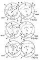
- FIGS. 3a to 3p The function of the pair of kneading discs 31 is shown in FIGS. 3a to 3p for one revolution explained.
- the cross section the axially open side also maximum and only decreases with the further rotation of the kneading disks 32, 33 in the direction of rotation 7 however, due to the reduction in cross section of the upper triangular volume 44 a large proportion of the product in it through a large cross-section always open in the direction of axis 5 or 6 kneaded.
- the each a kneading disk 32 or 33 assigned shut-off elements 46, 48 or 47, 49 are at an offset angle ⁇ with respect to the kneading disks 32, 33 offset, in the direction of rotation 7 leading. Because with this configuration if the product is squeezed, it will become one at a time such a combination of two kneading disks 32, 33 and four shut-off elements 46 to 49 referred to as a squeezer unit.
- the shut-off elements 46 to 49 each have a comb 50, two flanks 51, 52 and a bottom 53.
- the comb angles of the shut-off elements are equal to the comb angle ⁇ . If the offset angle ⁇ is larger than that Comb angle ⁇ , then the combination shown in Fig. 4a results. If - as shown there - the upper gusset triangle volume 44 of the leading comb tip 38 of the kneading disk 32 is then closed is this gusset triangle volume 44 in upstream and downstream Direction not completely closed by the shut-off elements 47, 49; it remains rather a so-called offset gap 54, through which among other things, product squeezed out of the gusset triangle volume 44 can be.
- the volume reduction of the gusset triangle volume 44 corresponds to the representation in FIG. 31 and then continues accordingly the representation in Fig. 3m to 3a. Repeated in the area of the lower gusset 41 this process according to the representation in FIGS. 3d to 3i, in which case the product is essentially due to the offset gap 55 flows out between the kneading disk 32 and the shut-off element 48.
- These offset gaps 54.55 are - based on the direction of rotation 7 - relative to the respective closed gusset triangle volume 44th or 45th trailing, so stay out while squeezing the product the closed gusset triangle volume 44.45 each open.
- Offset angle ⁇ is the same as shown in FIG. 4b the comb angle ⁇ of the kneading disk 32 or 33, then none is formed Offset gap. If, however, as shown in Fig. 4c Offset angle ⁇ is smaller than the comb angle ⁇ , then between the respective kneading disc 32 and 33 and the associated shut-off elements 46, 48 and 47, 49 each have a leading gap in the direction of rotation 55, but after closing the gusset triangle volume 44 accordingly 4c closed very quickly when turning further is so that only at the beginning of squeezing the gusset triangle volume 44 is squeezed out by this offset gap 55. When squeezing the closed lower, not shown in Fig. 4c A corresponding squeezing process takes place in the triangle volume.
- the kneading disks 32, 33 have an axial width b.
- 5a to 5d show the squeezing of the upper gusset triangle volume 44 of the embodiment according to FIG. 4a, for which ⁇ > ⁇ applies.
- the offset gap 54 during the rotary movement from the closing of the triangle volume 44 through the comb 34 of the kneading disk 33 (Fig. 5a) on the different rotation angle positions up to Arrival of the trailing comb tip 39 of the kneading disk 33 at the Gusset tip 42 always remains open in the direction of axis 5 or 6.
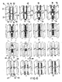
- a squeezer unit is in plan view in FIG. 6, So shown in a view from above, for the design 4a with an offset angle of ⁇ > ⁇ .
- the representation 6a corresponds to a plan view of FIG. 4a.
- the gusset triangle volume 44 becomes complete as shown in FIGS squeezed.
- the representations in FIGS. 6e to 61 opens the gusset area is complete and is replaced by the upstream Screw elements 18 are loaded with product again.
- the gusset triangle volume is formed again, it then closed again in the illustration according to FIG. 6a becomes.
- Fig. 7 shows four arranged one behind the other in the conveying direction 19 Squeezer units 57, 58, 59, 60, each constructed as it is is previously described, namely for an offset angle ⁇ > ⁇ .
- the four Squeezer units 57 to 60 are each offset by 90 ° arranged, namely - seen in the conveying direction 19 - opposite the next upstream squeezer unit against the direction of rotation 7.
- the position of the upstream squeezer unit 57 corresponds that shown in Fig. 6a.
- the position of the subsequent squeezer unit 58 corresponds to that shown in FIG. 6m.
- the position of the Squeezer unit 59 corresponds to that shown in Fig. 6i.
- the downstream located squeezer unit 60 is arranged according to Fig. 6e.
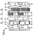
- shut-off elements 46, 47, 48, 49 are also formed by kneading disks
- the shut-off elements are also formed by catchy screw elements be, with a single catchable screw element simultaneously as downstream shut-off element of a squeezer unit and as an upstream one Shut off the next squeezer unit can.
- the shut-off takes place over the cross-sectional area of the screw element, that of the upstream kneading disc or downstream kneading disc is facing. This cross-sectional areas exercise the shut-off function.
- shut-off elements 46 ', 47', 48 ', 49' are referred to as shut-off elements 46 ', 47', 48 ', 49'. Otherwise, the same reference numbers are used as for the previous description.
- the shear and expansion flow of the squeezing process becomes particularly by squeezing in the gusset triangle volume 44 or 45 Product volume, the speed of shaft 3, 4 and the geometry the gaps through which the product is squeezed.
- the one to be squeezed, located in the triangle volume 44 or 45 Product volume is determined by the comb angle ⁇ , which is from Radius ratio Ra / Ri, the offset angle ⁇ and the width b of the Kneading discs 32 or 33 depends.
- the offset angle ⁇ and the width b of the kneading disks 32, 33 are of the basic geometry of the Co-rotating twin screw extruder independent and therefore freely selectable, so that the product volume to be squeezed meets the requirements of Processing process can be optimally adapted.
- the gaps or Gaps through which the product is squeezed become down limited by the minimal play required by mechanical engineering between the kneading disks 32, 33 and the housing 2. Further necessary Games exist between the kneading disks 32, 33 in the area of their respective Intervention. There is also axial play between the kneading disks 32,33 and the respective adjacent shut-off elements 46 to 49 and 46 'to 49' so that they can run past each other. This mechanically necessary minimal games can be increased are practically free based on their specified minimum values selectable.
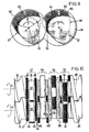
- the axial gaps required by mechanical engineering are as wet as in Fig. 9 - shown greatly exaggerated in Fig. 10.
- the axial column 65 between the kneading disks 32, 33 on the one hand and the shut-off elements 46, 48 and 47, 49 have an axial width c, which is in the range of a few Hundredths to a few tenths of a millimeter moved and their Size can also be optimized mechanically by appropriate selection can.
- the interpretation of all columns 63, 64, 65 and the offset gaps 54, 55 not only significantly influences the expansion and shear flow in these Areas, but also the flow of the product. So about sizing the gusset triangle volume 44, 45 and the column 63, 64, 65 and the offset gaps 54.55 the product stress, the product flow and the specific introduction of energy can be controlled in a targeted manner.
- shut-off elements 46 to 49 are in the manner of Kneading discs trained shut-off elements 46 to 49 arranged so that no gap is formed, so ⁇ applies.
- Shut-off elements 46 to 49 are provided with squeezing channels 66 and that is, in the vicinity of the trailing comb tip 67 of the respective shut-off element.
- squeeze channels 66 can instead of an offset gap or also be provided in addition to a very small offset gap. You can use both the upstream and the downstream arranged shut-off element 46, 47 or 48, 49 are formed, whereby targeted both the product load and the product flow can be controlled.
Landscapes
- Engineering & Computer Science (AREA)
- Mechanical Engineering (AREA)
- Extrusion Moulding Of Plastics Or The Like (AREA)
- Processing And Handling Of Plastics And Other Materials For Molding In General (AREA)
- Mixers Of The Rotary Stirring Type (AREA)
Abstract
Claims (9)
- Extrudcuse à deux vis à rotation identique,caractérisée en ce que,avec un carter (1),avec deux alésages de boítier (29, 30) parallèles l'un à l'autre, s'interpénétrant partiellement en formant deux goussets (40, 41),avec deux arbres (3, 4) entraínés en rotation dans le même sens, disposés dans les alésages de boítier (29, 30),avec des éléments de vis (12, 16, 18, 26) disposés sur les arbres (3, 4),avec au moins une paire de disques de pétrissage (31) dont chacune est formée d'un disque de pétrissage à filet unique (32, 33) solidarisé en rotation sur chaque arbre (3, 4) et pourvu d'un peigne (34) avec un angle de peigne γ, lesdits disques de pétrissage s'engrenant l'un avec l'autre et, lora d'un tour dans la direction de rotation (7), délimitant un volume triangulaire en gousset (44, 45) à section transversale au moins en grande partie fermée dans la zone de chaque gousset (40, 41),
de part et d'autre des disques de pétrissage (32, 33) formant une paire de disques de pétrissage (31), un élément de fermeture (46 à 49, 46' à 49') est solidarisé en rotation sur les arbres (3, 4) dans chacune des directions amont et aval, de façon que, parallèlement à la formation d'une unité d'écrasement (57 à 60, 57' à 60'), le volume triangulaire en gousset (44, 45) soit au moins en majeure partie fermé dans la direction des axes (5, 6) dans les directions amont et aval. - Extrudeuse à deux vis à rotation identique selon la revendication 1, caractérisée en ce que
les éléments de fermeture (46 à 49) sont conçus sous la forme de disques de pétrissage avec des géométries en coupe transversale au moins sensiblement identiques l'une à l'autre et à celle des disques de pétrissage (32, 33). - Extrudeuse à deux vis à rotation identique selon la revendication 1 ou 2, caractérisée en ce que
les éléments de fermeture (46 à 49) sont décalés selon un angle de décalage ε par rapport au disque de pétrissage respectif (32, 33) sur l'arbre respectif (3, 4). - Extrudeuse à deux vis à rotation identique selon la revendication 3, caractérisée en ce que,
en présence de la relation ε > γ, est formé un intervalle de déport (54, 55) qui ouvre partiellement le volume triangulaire en gousset (44, 45) dans les directions amont et/ou aval. - Extrudeuse à deux vis à rotation identique selon la revendication 3, caractérisée en ce que,
pour l'angle de décalage ε par rapport à l'angle de peigne γ, on a ; ε ≤ γ. - Extrudeuse à deux vis à rotation identique selon une des revendications 1 à 5, caractérisée en ce que
des canaux de pressage (66) sont ménagés dans au moins un élément de fermeture (46 à 49). - Extrudeuse à deux vis à rotation identique selon la revendication 1, caractérisée en ce que les éléments de fermeture (46' à 49') sont formés par des éléments de vis (61, 62).
- Extrudeuse à deux vis à rotation identique selon une des revendications 1 à 7, caractérisée en ce que,
entre les éléments de fermeture (46 à 49, 46' à 49') et le carter (2) est ménagé un interstice radial défini (63) et/ou dans la zone d'engrénement des disques de pétrissage (32, 33) d'une paire de disques de pétrissage (31) est ménagé un interstice radial défini (64) et/ou entre les disques de pétrissage (32, 33) d'une paire de disques de pétrissage (31) et les éléments de fermeture associés mutuellement par paires (46 à 49, 46' à 49') est ménagé un interstice axial défini (65). - Extrudeuse à deux vis à rotation identique selon une des revendications 1 à 8, caractérisée en ce que
plusieurs unités d'écrasement (57 à 60, 57' à 60') sont disposées directement les unes derrière les autres dans la direction axiale - avec des décalages mutuels par rapport à la direction de rotation (7).
Applications Claiming Priority (3)
| Application Number | Priority Date | Filing Date | Title |
|---|---|---|---|
| DE19845633 | 1998-10-05 | ||
| DE19845633 | 1998-10-05 | ||
| PCT/EP1999/007372 WO2000020188A1 (fr) | 1998-10-05 | 1999-10-05 | Extrudeuse a deux vis a rotation identique |
Publications (2)
| Publication Number | Publication Date |
|---|---|
| EP1121238A1 EP1121238A1 (fr) | 2001-08-08 |
| EP1121238B1 true EP1121238B1 (fr) | 2002-05-15 |
Family
ID=7883322
Family Applications (1)
| Application Number | Title | Priority Date | Filing Date |
|---|---|---|---|
| EP99952495A Expired - Lifetime EP1121238B1 (fr) | 1998-10-05 | 1999-10-05 | Extrudeuse a deux vis a rotation identique |
Country Status (4)
| Country | Link |
|---|---|
| EP (1) | EP1121238B1 (fr) |
| JP (1) | JP4484366B2 (fr) |
| DE (2) | DE19947967A1 (fr) |
| WO (1) | WO2000020188A1 (fr) |
Cited By (1)
| Publication number | Priority date | Publication date | Assignee | Title |
|---|---|---|---|---|
| EP1508424A1 (fr) | 2003-08-22 | 2005-02-23 | Coperion Werner & Pfleiderer GmbH & Co. KG | Machine à vis-sans-fin avec disques de pétrissage et malaxage |
Families Citing this family (6)
| Publication number | Priority date | Publication date | Assignee | Title |
|---|---|---|---|---|
| SG96260A1 (en) | 2000-11-17 | 2003-05-23 | Mitsui Chemicals Inc | Method for manufacturing olefinic thermoplastic elastomer composition |
| DE10112028A1 (de) * | 2001-03-06 | 2002-09-26 | Berstorff Gmbh | Schneckenpumpe und Doppelschneckenextruder mit einer solchen Schneckenpumpe |
| DE102008029306A1 (de) * | 2008-06-20 | 2009-12-24 | Bayer Technology Services Gmbh | Schneckenelemente mit reduziertem Energieeintrag beim Druckaufbau |
| JP5318709B2 (ja) * | 2009-08-26 | 2013-10-16 | ポリプラスチックス株式会社 | スクリューエレメントピース及びスクリュー |
| CN109695568B (zh) * | 2019-02-21 | 2024-06-04 | 威海智德真空科技有限公司 | 同向旋转共轭啮合的双螺杆 |
| EP4316762A1 (fr) * | 2022-08-05 | 2024-02-07 | Coperion GmbH | Élément de traitement permettant de traiter des matériaux au moyen d'une machine à vis |
Family Cites Families (8)
| Publication number | Priority date | Publication date | Assignee | Title |
|---|---|---|---|---|
| US2670188A (en) * | 1949-09-23 | 1954-02-23 | Bayer Ag | Mixing and kneading machine |
| NL128227C (fr) * | 1963-09-20 | 1900-01-01 | ||
| DE2802125B2 (de) * | 1978-01-19 | 1980-07-17 | Josef A. 7144 Asperg Blach | Schneckenmaschine zum Bearbeiten von festen, flüssigen und zähviskosen Materialien |
| DE3014643A1 (de) * | 1980-04-16 | 1981-10-22 | Bayer Ag, 5090 Leverkusen | Gleichsinnig rotierbare doppelschnecke |
| US4392967A (en) * | 1981-08-11 | 1983-07-12 | Exxon Research And Engineering Co. | Process for continuously manufacturing lubricating grease |
| US4752135A (en) * | 1986-12-01 | 1988-06-21 | Baker Perkins, Inc. | Mixing apparatus and methods |
| JPH0825456A (ja) * | 1994-07-20 | 1996-01-30 | Toshiba Mach Co Ltd | 2軸押出機の押出スクリュ |
| DE19718292A1 (de) * | 1997-04-30 | 1998-11-05 | Krupp Werner & Pfleiderer Gmbh | Mehrwellen-Schneckenmaschine, insbesondere Zwei-Wellen-Extruder |
-
1999
- 1999-10-05 JP JP2000573525A patent/JP4484366B2/ja not_active Expired - Lifetime
- 1999-10-05 DE DE19947967A patent/DE19947967A1/de not_active Withdrawn
- 1999-10-05 EP EP99952495A patent/EP1121238B1/fr not_active Expired - Lifetime
- 1999-10-05 WO PCT/EP1999/007372 patent/WO2000020188A1/fr not_active Ceased
- 1999-10-05 DE DE59901472T patent/DE59901472D1/de not_active Expired - Lifetime
Cited By (2)
| Publication number | Priority date | Publication date | Assignee | Title |
|---|---|---|---|---|
| EP1508424A1 (fr) | 2003-08-22 | 2005-02-23 | Coperion Werner & Pfleiderer GmbH & Co. KG | Machine à vis-sans-fin avec disques de pétrissage et malaxage |
| EP1508424B2 (fr) † | 2003-08-22 | 2016-10-26 | Coperion GmbH | Machine à vis-sans-fin avec disques de pétrissage et malaxage |
Also Published As
| Publication number | Publication date |
|---|---|
| WO2000020188A1 (fr) | 2000-04-13 |
| DE19947967A1 (de) | 2000-04-06 |
| EP1121238A1 (fr) | 2001-08-08 |
| JP2002526280A (ja) | 2002-08-20 |
| JP4484366B2 (ja) | 2010-06-16 |
| DE59901472D1 (de) | 2002-06-20 |
Similar Documents
| Publication | Publication Date | Title |
|---|---|---|
| EP0160124B1 (fr) | Pétrisseuse à double vis sans fin, tournant dans le même sens, avec disques de pétrissage | |
| EP0537450B1 (fr) | Pétrisseur à vis à torsion uniforme | |
| EP1390189B1 (fr) | Dispositif comportant des vis sans fin destine a l'homogeneisation et/ou a la dispersion | |
| EP0728066B1 (fr) | Melangeur a plusieurs arbres fonctionnant en continu pour matieres plastifiables | |
| EP0087699B1 (fr) | Machine à axes multiples pour mélanger et malaxer en continu des matières plastifiables, ayant des vis s'engrenant et tournant dans le même sens et à entr'axe constant | |
| EP1013402B1 (fr) | Extrudeuse à deux vis | |
| DE3011918A1 (de) | Fliessmischer | |
| EP0694378B1 (fr) | Extrudeuse à deux vis | |
| DE1729301B2 (fr) | ||
| EP3880429B1 (fr) | Extrudeuse de dégazage dotée d'une unité multivis et procédé permettant le dégazage d'une masse fondue polymère | |
| EP0346757A2 (fr) | Extrudeuse à deux vis | |
| EP2272651B1 (fr) | Machine à vis sans fin avec élément de malaxage dispersif | |
| EP2580042B1 (fr) | Dispositif de façonnage de matériau par mélange et/ou plastification | |
| DE10207145B4 (de) | Vorrichtung zum Dispergieren und Aufschmelzen fließfähiger Stoffe | |
| WO2007112861A1 (fr) | Element helicoidal | |
| EP1121238A1 (fr) | Extrudeuse a deux vis a rotation identique | |
| EP0641640B1 (fr) | Elément de vis-sans-fin pour une machine à vis-sans-fin | |
| EP1993807B1 (fr) | Vis d'extrudeuse | |
| EP4143001B1 (fr) | Unité de plastification | |
| DD146024A5 (de) | Extruder zur bearbeitung thermoplastischer materialien | |
| EP0490360A1 (fr) | Procédé et extrudeuse pour le traitement et la fabrication de matières caoutchouteuses ou plastiques | |
| DE3823222C2 (fr) | ||
| DE102011054409B4 (de) | Extrudervorrichtung und Extrusionsverfahren, insbesondere zur Compoundierung von Kunststoffen | |
| DE3404461C2 (de) | Vorrichtung zum Schmelzen und Fördern von plastifiziertem Material mit einer Extrudierschnecke | |
| DE2908497C2 (de) | Extruderschnecke |
Legal Events
| Date | Code | Title | Description |
|---|---|---|---|
| PUAI | Public reference made under article 153(3) epc to a published international application that has entered the european phase |
Free format text: ORIGINAL CODE: 0009012 |
|
| 17P | Request for examination filed |
Effective date: 20010320 |
|
| AK | Designated contracting states |
Kind code of ref document: A1 Designated state(s): AT BE CH CY DE DK ES FI FR GB GR IE IT LI LU MC NL PT SE |
|
| GRAG | Despatch of communication of intention to grant |
Free format text: ORIGINAL CODE: EPIDOS AGRA |
|
| 17Q | First examination report despatched |
Effective date: 20020108 |
|
| GRAG | Despatch of communication of intention to grant |
Free format text: ORIGINAL CODE: EPIDOS AGRA |
|
| GRAH | Despatch of communication of intention to grant a patent |
Free format text: ORIGINAL CODE: EPIDOS IGRA |
|
| GRAH | Despatch of communication of intention to grant a patent |
Free format text: ORIGINAL CODE: EPIDOS IGRA |
|
| RAP1 | Party data changed (applicant data changed or rights of an application transferred) |
Owner name: COPERION WERNER & PFLEIDERER GMBH & CO. KG |
|
| GRAA | (expected) grant |
Free format text: ORIGINAL CODE: 0009210 |
|
| AK | Designated contracting states |
Kind code of ref document: B1 Designated state(s): BE DE FR GB IT NL |
|
| REG | Reference to a national code |
Ref country code: GB Ref legal event code: FG4D Free format text: NOT ENGLISH |
|
| GBT | Gb: translation of ep patent filed (gb section 77(6)(a)/1977) |
Effective date: 20020516 |
|
| REG | Reference to a national code |
Ref country code: IE Ref legal event code: FG4D Free format text: GERMAN |
|
| REF | Corresponds to: |
Ref document number: 59901472 Country of ref document: DE Date of ref document: 20020620 |
|
| ET | Fr: translation filed | ||
| REG | Reference to a national code |
Ref country code: IE Ref legal event code: FD4D Ref document number: 1121238E Country of ref document: IE |
|
| PLBE | No opposition filed within time limit |
Free format text: ORIGINAL CODE: 0009261 |
|
| STAA | Information on the status of an ep patent application or granted ep patent |
Free format text: STATUS: NO OPPOSITION FILED WITHIN TIME LIMIT |
|
| 26N | No opposition filed |
Effective date: 20030218 |
|
| PGFP | Annual fee paid to national office [announced via postgrant information from national office to epo] |
Ref country code: NL Payment date: 20041019 Year of fee payment: 6 |
|
| PGFP | Annual fee paid to national office [announced via postgrant information from national office to epo] |
Ref country code: BE Payment date: 20041022 Year of fee payment: 6 |
|
| PG25 | Lapsed in a contracting state [announced via postgrant information from national office to epo] |
Ref country code: BE Free format text: LAPSE BECAUSE OF NON-PAYMENT OF DUE FEES Effective date: 20051031 |
|
| PG25 | Lapsed in a contracting state [announced via postgrant information from national office to epo] |
Ref country code: NL Free format text: LAPSE BECAUSE OF NON-PAYMENT OF DUE FEES Effective date: 20060501 |
|
| NLV4 | Nl: lapsed or anulled due to non-payment of the annual fee |
Effective date: 20060501 |
|
| BERE | Be: lapsed |
Owner name: *COPERION WERNER & PFLEIDERER G.M.B.H. & CO. K.G. Effective date: 20051031 |
|
| REG | Reference to a national code |
Ref country code: FR Ref legal event code: PLFP Year of fee payment: 17 |
|
| REG | Reference to a national code |
Ref country code: FR Ref legal event code: PLFP Year of fee payment: 18 |
|
| REG | Reference to a national code |
Ref country code: FR Ref legal event code: PLFP Year of fee payment: 19 |
|
| REG | Reference to a national code |
Ref country code: FR Ref legal event code: PLFP Year of fee payment: 20 |
|
| REG | Reference to a national code |
Ref country code: DE Ref legal event code: R079 Ref document number: 59901472 Country of ref document: DE Free format text: PREVIOUS MAIN CLASS: B29C0047400000 Ipc: B29C0048400000 |
|
| PGFP | Annual fee paid to national office [announced via postgrant information from national office to epo] |
Ref country code: FR Payment date: 20181023 Year of fee payment: 20 Ref country code: GB Payment date: 20181025 Year of fee payment: 20 Ref country code: IT Payment date: 20181022 Year of fee payment: 20 |
|
| PGFP | Annual fee paid to national office [announced via postgrant information from national office to epo] |
Ref country code: DE Payment date: 20181215 Year of fee payment: 20 |
|
| REG | Reference to a national code |
Ref country code: DE Ref legal event code: R071 Ref document number: 59901472 Country of ref document: DE |
|
| REG | Reference to a national code |
Ref country code: GB Ref legal event code: PE20 Expiry date: 20191004 |
|
| PG25 | Lapsed in a contracting state [announced via postgrant information from national office to epo] |
Ref country code: GB Free format text: LAPSE BECAUSE OF EXPIRATION OF PROTECTION Effective date: 20191004 |