EP2291632B1 - Vorrichtung zum entfernen von überschüssigem einbettmedium - Google Patents
Vorrichtung zum entfernen von überschüssigem einbettmedium Download PDFInfo
- Publication number
- EP2291632B1 EP2291632B1 EP09753509A EP09753509A EP2291632B1 EP 2291632 B1 EP2291632 B1 EP 2291632B1 EP 09753509 A EP09753509 A EP 09753509A EP 09753509 A EP09753509 A EP 09753509A EP 2291632 B1 EP2291632 B1 EP 2291632B1
- Authority
- EP
- European Patent Office
- Prior art keywords
- plate
- channels
- frame
- collection
- constructed
- Prior art date
- Legal status (The legal status is an assumption and is not a legal conclusion. Google has not performed a legal analysis and makes no representation as to the accuracy of the status listed.)
- Active
Links
Images


Classifications
-
- G—PHYSICS
- G01—MEASURING; TESTING
- G01N—INVESTIGATING OR ANALYSING MATERIALS BY DETERMINING THEIR CHEMICAL OR PHYSICAL PROPERTIES
- G01N1/00—Sampling; Preparing specimens for investigation
- G01N1/28—Preparing specimens for investigation including physical details of (bio-)chemical methods covered elsewhere, e.g. G01N33/50, C12Q
- G01N1/36—Embedding or analogous mounting of samples
Definitions
- the invention relates to a device for removing excess embedding medium from the surface of an embedded sample, in particular for removing wax from the outside of a tissue cassette, with a frame and a tiltable heated plate from the frame, wherein serving in the surface of the plate as gutters Grooves, grooves, depressions or the like.
- a device for removing excess embedding medium from the surface of an embedded sample in particular for removing wax from the outside of a tissue cassette, with a frame and a tiltable heated plate from the frame, wherein serving in the surface of the plate as gutters Grooves, grooves, depressions or the like.
- gutters Grooves, grooves, depressions or the like are designed for receiving and discharging abraded and molten embedding medium, which open into a collecting channel.
- Devices of the generic type are used in pathology or histology, namely in the preparation of tissues or tissue samples for examinations.
- the tissue samples are embedded in an embedding medium, preferably in a so-called tissue cassette.
- the tissue sample can be handled. Wax or paraffin is used regularly for embedding, which is melted for this purpose.
- tissue samples or the cassette carrying the tissue sample can be placed and adjusted properly and reproducibly. If there are paraffin residues on the embedded sample or on the tissue cassette, an adjustment or perfect positioning of the tissue sample is not possible. Consequently, it is necessary to remove excess embedding medium prior to the actual examination in order to be able to exclude an incorrect positioning of the tissue sample.
- a generic device for removing excess embedding medium from the surface of an embedded sample, particularly from the outside of a tissue cassette.
- the known device comprises a frame, of which a heatable plate is held in an inclined or oblique position.
- the plate comprises a structured surface, namely a surface provided with grooves, grooves, depressions or the like, whereafter a plurality of gutters running parallel to one another are formed.
- the Drainage channels run obliquely on the plate surface, namely in the direction of the inclination generated by tilting the plate down, so that stripped wax melts by heating the plate and runs in the gutters - by gravity - to an edge region of the plate.
- the molten wax can run exclusively in one direction, namely in the direction of the inclined grooves, so that especially when removing large quantities of wax or simultaneous treatment of multiple tissue samples overfilling of the gutters or a backwater and thus overflow can take place. If tissue samples continue to be processed, the excess wax is smeared on the surface of the plate and can be removed with a great deal of time delay. The editing process is hampered in any case.
- the gutters are chamfered in one direction, so that the scraping of the embedded sample or the tissue cassette can only take place in one direction, namely transversely to the gutters. Consequently, the known device is always suitable only for right-handed or left-handed, at least can not be used in both directions of movement to move the sample or tissue cassette.
- the present invention is based on the object, such a device of the generic type and further develop that can be easily dissipate with sufficient reliability even larger amounts of excess embedding, without having to make a cumbersome positioning of collecting containers.
- the above object is achieved by a device with the features of claim 1. Thereafter, the generic device is characterized in that the gutters of a respective highest Point on both sides outward sloping in collecting channels lead to a collecting container.
- the device for abschabenden movement of the sample or tissue cassettes can be used in different directions, namely, when the grooves are executed from a respective highest point on both sides sloping outwards.
- the grooves starting from an imaginary center line, are designed to descend to the left and to the right, respectively, so that the sample or tissue cassette can be guided at different angles at an angle to the groove. Consequently, the device is suitable for both right-handed and left-handed, namely for moving the sample in two different directions.
- the grooves on both sides open outwardly sloping into collecting channels, namely in collecting channels, which are arranged on both sides of the grooves or rotate these.
- the collecting channels in turn lead to a collecting container, which is associated with the device. This ensures that scraped and molten embedding medium collect on the gutters in the collecting channel and run from there into the collecting container or drain. Special measures for collecting the scraped and molten embedding medium are not required.
- the gutters are formed in an advantageous manner symmetrical with equally long drainage arms on both sides, as well as an asymmetrical configuration with drain arms of different lengths on both sides is possible.
- a symmetrical configuration has the advantage that the embedded sample or tissue cassette can be freed from the embedding medium from two directions with sufficiently good effect, since the arrangement of the gutters essentially permits two directions of movement for stripping the embedding medium.
- gutters are arranged one below the other along the length of the plate so that multiple stripping is possible.
- the arrangement of several gutters has the advantage that at the same time several samples or tissue cassettes can be moved over the plate.
- the gutters can run parallel to each other. It is also conceivable that the gutters divergently fan or converge. Such an arrangement would have the advantage that small samples in the area of the closely spaced gutters and larger samples in the area of the gutters lying further apart can be stripped off.
- the gutters open on both sides into a collecting channel and thus together with the collecting channels form a communicating gutter system. This ensures that the stripped embedding medium, which runs in the molten state along the gutters, passes through the collecting channels into the collecting container. It must be ensured that the plate has a more or less uniform temperature across the entire channel system, in which the embedding medium is sufficiently fluid to move along the slope through the channel system.
- the collecting channels open near the lowest point of the plate or directly at a lowest point of the plate in a drip area, which is located above the collecting container.
- the dripping area comprises a recess in the plate into which the collecting channels open or into which the collecting channels open.
- the drip area may include a drip tip or the like directed downwards so that the embedding medium is specifically directed into the collecting receptacle located underneath.
- gutters serve on the one hand to strip off the excess embedding medium and on the other hand to drain off the stripped and molten embedding medium. It is advantageous if the edges of the gutters are sharp-edged, so that the excess embedding can effectively strip.
- the bottom or groove bottom of the gutters and possibly the collecting gutters is preferably rounded, namely to favor the flow of the molten embedding medium.
- the embedding medium in the flow obstructing capillary effects in corner regions of the gutter system should be avoided.
- the surfaces between the gutters namely located between the gutters surfaces of the plate are at least slightly inclined to each other, so that always one edge of the gutter is raised relative to the other edge.
- sharp-edged design is favored by this measure, the abrasive effect or stripping of the respective raised edge.
- the plate is heated. It is essential that the plate temperature is maintained at which the embedding medium, for example. Wax or paraffin, can run relatively thin liquid in the gutter system along the slope. Temperatures in the range between 50 ° C and 60 ° C are to be realized on the surface of the plate.
- the frame is associated with an electric heater with at least one heating element.
- the heating element may be directly associated with the plate, preferably on its underside.
- the heating element is integrated in the plate or designed as a plate.
- the heating element could be designed in the sense of a heating plate and thus represent the plate itself or be firmly connected below the plate with this.
- An adhesive connection of a heating plate with the actual plate is conceivable.
- the plate it is advantageous if it can be removed from the frame, on the one hand for the purpose of cleaning and on the other hand for replacement against another plate. Accordingly, it is advantageous if the plate is inserted or plugged into the frame. In any case, the plate should be releasably connected to the frame. In the case of a ferromagnetic embodiment of the plate, it is conceivable that the plate is connected to the frame via magnetic forces. Such a connection is, for example, also possible because the plate is associated with a magnetic strip in the edge region.
- the heating element associated with the plate is to be electrically contacted.
- at least one plug-in connection could be provided for fixing the plate, which comprises an electrical connection for the heating device.
- the mechanical and electrical coupling of the plate could be realized by the same measure.
- the heating device comprises a control or regulation for the temperature of the plate. It should be ensured that the plate is stable at a constant outside temperature, namely to be able to ensure a safe operation of the device for a long time. It is also advantageous if predefinable temperatures can be preselected or selected.
- the plate is advantageously made of metal. It makes sense to manufacture the plate made of aluminum or an aluminum alloy. An injection molding / die casting production is possible. It is also conceivable to work the plate from the solid.
- At least two plates with a different surface structure are provided for replacement, so that it is possible to tailor the device to the specific requirements, namely by providing different surface structures.
- the collecting container is located below the lowest point of the plate and extends in an advantageous manner at least slightly into the frame.
- the collecting container could be designed as a completely removable drawer, so that an isolated cleaning of the drawer is possible.
- the frame is wedge-shaped, so that the gutter system is particularly suitable for the course of the molten embedding medium according to the inclination of the frame.
- the frame is designed as a housing with a front opening for inserting the collecting container.
- the collecting container may be made of plastic, but also of the same material as the plate.
- the housing is also made of aluminum or an aluminum alloy in a further advantageous manner.
- the plate can serve as a cover of the housing, so that it closes the housing upwards.
- Within the housing is the required electrical / electronic, in particular the heater and its control / regulation.
- the housing is also closed, namely by a bottom plate screwed from below.
- a bottom plate screwed from below.
- four rubber buffers can be provided as non-slip adjustable feet.
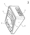
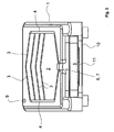
- the Fig. 1 to 4 show an embodiment of an inventive device for removing excess embedding medium from the surface of an embedded sample, wherein the embedding medium is regularly wax or paraffin. Usually, it is about removing the excess paraffin from the outside of a tissue cassette in which a tissue sample is embedded.
- the device comprises a housing 1 designed as a frame 1 and held by the frame 1 with tilt plate 2.
- the plate 2 is heated from the bottom. It serves on the one hand to strip off the excess embedding medium and on the other hand to liquefy the medium so that it can be removed via the plate.
- 2 drainage grooves 3 are formed in the surface of the plate in the form of grooves, which serve for receiving and discharging the abraded and molten embedding medium.
- the gutters 3 open into lateral collecting troughs 4.
- the gutters 3 are designed such that they discharge from a respective highest point on both sides sloping outwards into the collecting channels 4. Accordingly, the gutters are 3 V-shaped, sloping down, executed, the collecting channels 4 lead to a collecting container 5.
- the gutters 3 are formed symmetrically with equally long drainage arms on both sides.
- the figures further show that the collecting channels 4 open near a lowest point of the plate 2 in a drip area 6 above the collecting container 5.
- the drip area 6 comprises a recess 7 in the plate 2, into which the collecting channels 4 open.
- edges of the gutters 3 are sharp-edged to favor the stripping.
- the respective groove bottom is rounded, so that the flow of liquid paraffin is guaranteed.
- the plate 2 is electrically heated. Concretely located on the underside of the plate 2 is a heating plate, which is part of an integrated heater.
- Fig. 2 shows the electrical connection 8 for the heater, where there is not shown in the figure device plug can be inserted, a warning light 9 indicates whether the device is turned on.
- a warning light 9 indicates whether the device is turned on.
- the plate 2 is inserted or inserted into the designed as a housing frame 1 and locked there. For example, it is possible to screw the plate 2 from below firmly to the frame 1.
- the figures furthermore clearly show the collecting container 5, which is designed as a drawer and inserted into a lower region of the frame 1 or, respectively, of the housing.
- the collecting container 5 is located directly below the drip area 6 or the recess 7 forming the drip area 6, so that the embedding agent flowing by gravity in the gutter system into the collecting container 5 can drain. A simple extraction or removal and cleaning of the collecting container 5 is ensured due to the selected design as a drawer.
- Both the plate 2 and the frame 1 and the housing may be made of aluminum.
- the frame 1 can be made in one piece, wherein the plate 2, the frame 1 or housing from above and a purely in Fig. 4 Bottom plate 10 shown to complete the frame 1 or housing from below.
- the serving for receiving the collecting container 5 compartment is limited according to the dimensions of the collecting container 5 to the inside, so that the interior of the frame 1 or housing is completely completed.
Landscapes
- Physics & Mathematics (AREA)
- Health & Medical Sciences (AREA)
- Life Sciences & Earth Sciences (AREA)
- Chemical & Material Sciences (AREA)
- Analytical Chemistry (AREA)
- Biochemistry (AREA)
- General Health & Medical Sciences (AREA)
- General Physics & Mathematics (AREA)
- Immunology (AREA)
- Pathology (AREA)
- Sampling And Sample Adjustment (AREA)
- Coating Apparatus (AREA)
Description
- Die Erfindung betrifft eine Vorrichtung zum Entfernen von überschüssigem Einbettmedium von der Oberfläche einer eingebetteten Probe, insbesondere zum Entfernen von Wachs von der Außenseite einer Gewebekassette, mit einem Gestell und einer vom Gestell mit Neigung gehaltenen beheizbaren Platte, wobei in der Oberfläche der Platte als Ablaufrinnen dienende Nuten, Rillen, Vertiefungen oder dgl. zur Aufnahme und Ableitung von abgeriebenem und geschmolzenem Einbettmedium ausgebildet sind, die in eine Sammelrinne münden.
- Vorrichtungen der gattungsbildenden Art werden in der Pathologie bzw. Histologie verwendet, nämlich beim Präparieren von Geweben bzw. Gewebsproben für Untersuchungen. Insbesondere werden die Gewebsproben nach einer Behandlung in ein Einbettmedium eingebettet, vorzugsweise in einer sog. Gewebekassette. Durch diese Maßnahme lässt sich die Gewebsprobe handhaben. Zum Einbetten dient regelmäßig Wachs bzw. Paraffin, welches zu diesem Zwecke geschmolzen wird.
- Zur anschließenden Untersuchung, bspw. im Rahmen der Fluoreszenzmikroskopie, ist es erforderlich, dass sich die Gewebsproben bzw. die die Gewebsprobe tragende Kassette einwandfrei und reproduzierbar platzieren bzw. justieren lässt. Befinden sich an der eingebetteten Probe bzw. an der Gewebekassette Paraffinreste, so ist eine Justage bzw. einwandfreie Positionierung der Gewebsprobe nicht möglich. Folglich ist es erforderlich, überschüssiges Einbettmedium vor der eigentlichen Untersuchung zu entfernen, um nämlich eine Fehlpositionierung der Gewebsprobe ausschließen zu können.
- Aus der
WO 2002/023157 A2 ist eine gattungsbildende Vorrichtung bekannt, mit der sich überschüssiges Einbettmedium von der Oberfläche einer eingebetteten Probe, insbesondere von der Außenseite einer Gewebekassette, entfernen lässt. Die bekannte Vorrichtung umfasst ein Gestell, von dem eine beheizbare Platte in geneigter bzw. schräger Position gehalten ist. Die Platte umfasst eine strukturierte Oberfläche, nämlich eine mit Nuten, Rillen, Vertiefungen oder dgl. ausgestattete Oberfläche, wonach mehrere parallel zueinander verlaufende Ablaufrinnen ausgebildet sind. Die Ablaufrinnen verlaufen schräg auf der Plattenoberfläche, nämlich in Richtung der durch Schrägstellung der Platte erzeugten Neigung nach untern, so dass abgestreiftes Wachs durch die Beheizung der Platte schmilzt und in den Ablaufrinnen - über Schwerkraft - zu einem Randbereich der Platte läuft. Dort befindet sich eine Sammelrinne, in die die Ablaufrinnen allesamt münden. Von dort aus kann das entfernte Wachs in eine entsprechend positionierte Schale abtropfen, die in der Vorrichtung jedoch nicht vorgesehen ist. - Die aus der
WO 2002/023157 A2 bekannte Vorrichtung ist insoweit problematisch, als es stets erforderlich ist, das über die Ablaufrinnen und Sammelrinne ablaufende Wachs in einem separaten Behältnis zu sammeln. Dieses Behältnis ist stets relativ zu der Vorrichtung zu positionieren. Dies ist umständlich. - Außerdem kann das geschmolzene Wachs ausschließlich in eine Richtung, nämlich in Richtung der geneigten Rillen, ablaufen, so dass gerade beim Entfernen großer Mengen Wachs oder bei gleichzeitiger Behandlung mehrerer Gewebsproben ein Überfüllen der Ablaufrinnen bzw. ein Rückstau und somit Überlauf stattfinden kann. Werden dabei weiterhin Gewebeproben bearbeitet, wird das überschüssige Wachs regelrecht auf der Oberfläche der Platte verschmiert und lässt sich allenfalls stark zeitverzögert abführen. Der Bearbeitungsprozess ist dadurch jedenfalls behindert.
- Des Weiteren ist bei der gattungsbildenden Vorrichtung nachteilig, dass die Ablaufrinnen in eine Richtung abgeschrägt verlaufen, so dass das Abschaben der eingebetteten Probe bzw. der Gewebekassette nur in eine Richtung, nämlich quer zu den Ablaufrinnen, erfolgen kann. Folglich ist die bekannte Vorrichtung immer nur für Rechtshänder oder Linkshänder geeignet, lässt sich jedenfalls nicht in beide Bewegungsrichtungen zum Bewegen der Probe bzw. Gewebekassette nutzen.
- Der vorliegenden Erfindung liegt nun die Aufgabe zugrunde, eine Vorrichtung der gattungsbildenden Art derart auszugestalten und weiterzubilden, dass sich bei hinreichender Betriebssicherheit mühelos auch größere Mengen an überschüssigem Einbettmedium abführen lassen, ohne dabei ein umständliches Positionieren von Auffangbehältnissen vornehmen zu müssen.
- Die voranstehende Aufgabe wird erfindungsgemäß durch eine Vorrichtung mit den Merkmalen des Patentanspruchs 1 gelöst. Danach ist die gattungsbildende Vorrichtung dadurch gekennzeichnet, dass die Ablaufrinnen von einem jeweils höchsten Punkt beidseitig nach außen abfallend in Sammelrinnen münden, die zu einem Auffangbehältnis führen.
- Erfindungsgemäß ist erkannt worden, dass sich die Vorrichtung zur abschabenden Bewegung der Probe bzw. Gewebekassetten in unterschiedlichen Richtungen verwenden lässt, wenn nämlich die Nuten von einem jeweils höchsten Punkt beidseitig nach außen abfallend ausgeführt sind. Folglich sind die Nuten, ausgehend von einer gedachten Mitteillinie, jeweils nach links und nach rechts abfallend ausgeführt, so dass die Probe bzw. Gewebekassette unter unterschiedlichen Winkeln schräg zur Nut geführt werden kann. Folglich eignet sich die Vorrichtung sowohl für Rechtshänder als auch für Linkshänder, nämlich zur Bewegung der Probe in zwei unterschiedlichen Richtungen.
- Des Weiteren ist von ganz besonderem Vorteil, dass die Nuten beidseitig nach außen abfallend in Sammelrinnen münden, nämlich in Sammelrinnen, die beidseitig der Nuten angeordnet sind bzw. diese umlaufen. Die Sammelrinnen führen wiederum zu einem Auffangbehältnis, welches der Vorrichtung zugeordnet ist. Somit ist gewährleistet, dass sich abgeschabtes und geschmolzenes Einbettmedium über die Ablaufrinnen in die Sammelrinne hinein sammeln und von dort aus in das Auffangbehältnis laufen bzw. abtropfen. Besondere Maßnahmen zum Auffangen des abgeschabten und geschmolzenen Einbettmediums sind nicht erforderlich.
- Die Ablaufrinnen sind in vorteilhafter Weise symmetrisch mit beidseitig gleich langen Ablaufarmen ausgebildet, wobei ebenso eine asymmetrische Ausgestaltung mit beidseitig unterschiedlich langen Ablaufarmen möglich ist. Eine symmetrische Ausgestaltung hat den Vorteil, dass die eingebettete Probe bzw. Gewebekassette aus zwei Richtungen mit hinreichend guter Wirkung vom Einbettmedium befreit werden kann, da nämlich die Anordnung der Ablaufrinnen im Wesentlichen zwei Bewegungsrichtungen zum Abstreifen des Einbettmediums zulässt.
- Des Weiteren ist es von Vorteil, wenn über die Länge der Platte hinweg mehrere Ablaufrinnen untereinander angeordnet sind, so dass ein mehrfaches Abstreifen möglich ist. Außerdem hat die Anordnung mehrerer Ablaufrinnen den Vorteil, dass gleichzeitig mehrere Proben bzw. Gewebekassetten über die Platte bewegt werden können.
- Die Ablaufrinnen können parallel zueinander verlaufen. Ebenso ist es denkbar, dass die Ablaufrinnen fächerartig divergieren bzw. konvergieren. Eine solche Anordnung hätte den Vorteil, dass kleine Proben im Bereich der eng beieinander liegenden Ablaufrinnen und größere Proben im Bereich der weiter auseinander liegenden Ablaufrinnen abgestreift werden können.
- Wie bereits zuvor ausgeführt, münden die Ablaufrinnen beidseitig in jeweils eine Sammelrinne und bilden somit gemeinsam mit den Sammelrinnen ein kommunizierendes Rinnensystem. Dadurch ist gewährleistet, dass das abgestreifte Einbettmedium, welches im geschmolzenen Zustand entlang der Ablaufrinnen läuft, über die Sammelrinnen in das Auffangbehältnis gelangt. Dabei ist zu gewährleisten, dass die Platte Ober das gesamte Rinnensystem hinweg eine mehr oder weniger gleichmäßige Temperatur aufweist, bei der das Einbettmedium hinreichend dünnflüssig ist, um sich entlang des Gefälles durch das Rinnensystem hindurch zu bewegen.
- In ganz besonders vorteilhafter Weise münden die Sammelrinnen nahe des tiefsten Punktes der Platte oder direkt an einem tiefsten Punkt der Platte in einen Abtropfbereich, der sich oberhalb des Auffangbehältnisses befindet. Der Abtropfbereich umfasst eine Ausnehmung in der Platte in die die Sammelrinnen münden bzw. in die sich die Sammelrinnen öffnen. Der Abtropfbereich kann eine nach unten gerichtete Abtropfnase oder dgl. umfassen, damit nämlich das Einbettmedium gezielt in das sich darunter befindliche Auffangbehältnis geleitet wird.
- In Bezug auf die Ablaufrinnen sei angemerkt, dass diese einerseits zum Abstreifen des überschüssigen Einbettmediums und andererseits zum Ablauf des abgestreiften und geschmolzenen Einbettmediums dienen. Dabei ist es von Vorteil, wenn die Ränder der Ablaufrinnen scharfkantig ausgebildet sind, so dass sich das überschüssige Einbettmedium wirkungsvoll abstreifen lässt.
- Der Boden bzw. Nutengrund der Ablaufrinnen und ggf. der Sammelrinnen ist vorzugsweise abgerundet, um nämlich den Ablauf des geschmolzenen Einbettmediums zu begünstigen. Jedenfalls sollten das Einbettmedium im Fluss behindernde Kapillarwirkungen in Eckbereichen des Rinnensystems vermieden sein.
- Auch ist es denkbar, dass die Flächen zwischen den Ablaufrinnen, nämlich die zwischen den Ablaufrinnen befindlichen Oberflächen der Platte, zumindest geringfügig zueinander geneigt sind, so dass stets die eine Kante der Ablaufrinne gegenüber der anderen Kante erhaben ist. Bei entsprechend scharfkantiger Ausgestaltung wird durch diese Maßnahme der abrasive Effekt bzw. das Abstreifen an der jeweils erhabenen Kante begünstigt.
- Zuvor ist ebenfalls bereits ausgeführt worden, dass die Platte beheizt ist. Dabei ist wesentlich, dass die Plattentemperatur gehalten wird, bei der das Einbettmedium, bspw. Wachs bzw. Paraffin, relativ dünnflüssig im Rinnensystem entlang des Gefälles laufen kann. Temperaturen im Bereich zwischen 50°C und 60°C sind dabei an der Oberfläche der Platte zu realisieren. In vorteilhafter Weise ist dazu dem Gestell eine elektrische Heizeinrichtung mit mindestens einem Heizelement zugeordnet. Das Heizelement kann unmittelbar der Platte, vorzugsweise auf deren Unterseite, zugeordnet sein.
- Grundsätzlich ist es denkbar, dass das Heizelement in die Platte integriert bzw. als Platte ausgeführt ist. Mit anderen Worten könnte das Heizelement im Sinne einer Heizplatte ausgeführt sein und somit die Platte selbst darstellen oder unterhalb der Platte mit dieser fest verbunden sein. Eine klebetechnische Verbindung einer Heizplatte mit der eigentlichen Platte ist denkbar.
- Wesentlich ist jedenfalls, dass zwischen einer etwaigen Heizplatte bzw. Heizleitern und der Platte ein hinreichend guter Wärmeübergang realisiert ist.
- In Bezug auf die Platte ist es von Vorteil, wenn sich diese aus dem Gestell entfernen lässt, nämlich einerseits zum Zwecke der Reinigung und andererseits zum Austausch gegen eine andere Platte. Entsprechend ist es von Vorteil, wenn die Platte in das Gestell eingelegt oder eingesteckt ist. Jedenfalls sollte die Platte lösbar mit dem Gestell verbunden sein. Im Falle einer ferromagnetischen Ausgestaltung der Platte ist es denkbar, dass die Platte über Magnetkräfte mit dem Gestell verbunden ist. Eine solche Verbindung ist bspw. auch dadurch möglich, dass der Platte im Randbereich ein Magnetstreifen zugeordnet ist.
- Das der Platte zugeordnete Heizelement ist elektrisch zu kontaktieren. Dazu könnte zum Festlegen der Platte mindestens eine Steckverbindung vorgesehen sein, die einen elektrischen Anschluss für die Heizeinrichtung umfasst. Damit könnte das mechanische und elektrische Ankoppeln der Platte durch die gleiche Maßnahme realisiert sein.
- In weiter vorteilhafter Weise umfasst die Heizeinrichtung eine Steuerung oder Regelung für die Temperatur der Platte. Dabei sollte gewährleistet sein, dass die Platte auf einer konstanten Außentemperatur haltbar ist, um nämlich auch über eine längere Zeit hinweg einen sicheren Betrieb der Vorrichtung gewährleisten zu können. Auch ist es von Vorteil, wenn vorgebbare Temperaturen voreinstellbar bzw. wählbar sind. Die Platte ist in vorteilhafter Weise aus Metall gefertigt. Es bietet sich an, die Platte aus Aluminium oder aus einer Aluminiumlegierung zu fertigen. Eine spritzguss/druckgusstechnische Herstellung ist möglich. Auch ist es denkbar, die Platte aus dem Vollen zu arbeiten.
- In weiter vorteilhafter Weise sind mindestens zwei Platten mit unterschiedlicher Oberflächenstruktur zum Austausch vorgesehen, so dass es möglich ist, die Vorrichtung auf den konkreten Bedarf abzustimmen, nämlich durch Bereitstellung unterschiedlicher Oberflächenstrukturen.
- Das Auffangbehältnis befindet sich unterhalb des tiefsten Punktes der Platte und erstreckt sich in vorteilhafter Weise zumindest geringfügig in das Gestell hinein. Dabei könnte das Auffangbehältnis als komplett herausziehbare Schublade ausgeführt sein, so dass eine isolierte Reinigung der Schublade möglich ist.
- In Bezug auf die erforderliche Schrägstellung der Platte ist es vorteilhaft, wenn das Gestell keilförmig ausgebildet ist, so dass sich das Rinnensystem entsprechend der Neigung des Gestells ganz besonders zum Ablauf des geschmolzenen Einbettmediums eignet.
- Im Konkreten ist es von Vorteil, wenn das Gestell als Gehäuse mit einer vorderseitigen Öffnung zum Einschieben des Auffangbehältnisses ausgeführt ist. Das Auffangbehältnis kann aus Kunststoff, aber auch aus dem gleichen Material wie die Platte ausgeführt sein. Das Gehäuse ist in weiter vorteilhafter Weise ebenfalls aus Aluminium bzw. einer Aluminiumlegierung gefertigt. Die Platte kann als Abdeckung des Gehäuses dienen, so dass diese das Gehäuse nach oben abschließt. Innerhalb des Gehäuses befindet sich die erforderliche Elektrik/Elektronik, insbesondere die Heizeinrichtung und deren Steuerung/Regelung.
- Von der Unterseite her ist das Gehäuse ebenfalls geschlossen, nämlich durch eine von unterhalb angeschraubte Bodenplatte. Mit der Verschraubung können bspw. vier Gummipuffer als rutschsichere Stellfüße vorgesehen sein.
- Es gibt nun verschiedene Möglichkeiten, die Lehre der vorliegenden Erfindung in vorteilhafter Weise auszugestalten und weiterzubilden. Dazu ist einerseits auf die dem Patentanspruch 1 nachgeordneten Patentansprüche und andererseits auf die nachfolgende Erläuterung eines Ausführungsbeispiels der Erfindung anhand der Zeichnungen zu verweisen. In Verbindung mit der Erläuterung des bevorzugten Ausführungsbeispiels der Erfindung anhand der Zeichnungen werden auch im Allgemeinen bevorzugte Ausgestaltungen und Weiterbildungen der Lehre erläutert. In den Zeichnungen zeigt
- Fig. 1
- in einer schematischen Ansicht ein Ausführungsbeispiel einer erfindungsgemäßen Vorrichtung, schräg von vorne,
- Fig. 2
- in einer schematischen Ansicht den Gegenstand aus
Fig. 1 , schräg von hinten, - Fig. 3
- in einer schematischen Ansicht den Gegenstand aus den
Fig. 1 und , von vorne und - Fig. 4
- in einer Sprengdarstellung einzelne Bestandteile der Vorrichtung nach den
Fig. 1 bis 3 . - Die
Fig. 1 bis 4 zeigen ein Ausführungsbeispiel einer erfindungsgemäßen Vorrichtung zum Entfernen von überschüssigem Einbettmedium von der Oberfläche einer eingebetteten Probe, wobei es sich bei dem Einbettmedium regelmäßig um Wachs bzw. Paraffin handelt. Üblicherweise geht es darum, das überschüssige Paraffin von der Außenseite einer Gewebekassette zu entfernen, in die eine Gewebsprobe eingebettet ist. - Die Vorrichtung umfasst ein als Gehäuse ausgeführtes Gestell 1 und eine vom Gestell 1 mit Neigung gehaltene Platte 2. Die Platte 2 ist von der Unterseite her beheizt. Sie dient einerseits zum Abstreifen des überschüssigen Einbettmediums und andererseits zum Verflüssigen des Mediums, so dass es über die Platte abgeführt werden kann. Im Konkreten sind in der Oberfläche der Platte 2 Ablaufrinnen 3 in Form von Nuten ausgebildet, die zur Aufnahme und Ableitung des abgeriebenen und geschmolzenen Einbettmediums dienen. Die Ablaufrinnen 3 münden in seitlichen Sammelrinnen 4.
- Erfindungsgemäß sind die Ablaufrinnen 3 derart ausgebildet, dass sie von einem jeweils höchsten Punkt beidseitig nach außen abfallend in die Sammelrinnen 4 münden. Entsprechend sind die Ablaufrinnen 3 V-förmig, nach unten abfallend, ausgeführt, wobei die Sammelrinnen 4 zu einem Auffangbehältnis 5 führen.
- Bei dem in den Figuren gezeigten Ausführungsbeispiel sind die Ablaufrinnen 3 symmetrisch mit beidseitig gleich langen Ablaufarmen ausgebildet. Außerdem befinden sich untereinander vier identische Ablaufrinnen 3, die einen identischen Abstand zueinander haben und parallel zueinander verlaufen. Gemeinsam mit den seitlichen Sammelrinnen 4 bilden die Ablaufrinnen 3 ein kommunizierendes Rinnensystem, welches einerseits zum Abreiben des überschüssigen Einbettmediums und andererseits zum Verflüssigen und Abführen des abgestreiften Einbettmediums dienen.
- Die Fig. lassen des Weiteren erkennen, dass die Sammelrinnen 4 nahe eines tiefsten Punktes der Platte 2 in einen Abtropfbereich 6 oberhalb des Auffangbehältnisses 5 münden. Im Konkreten umfasst der Abtropfbereich 6 eine Ausnehmung 7 in der Platte 2, in die die Sammelrinnen 4 münden.
- Die Ränder der Ablaufrinnen 3 sind zur Begünstigung des Abstreifens scharfkantig ausgebildet. Der jeweilige Nutengrund ist abgerundet, so dass der Ablauf des flüssigen Paraffins gewährleistet ist.
- Die Platte 2 ist elektrisch beheizt. Im Konkreten befindet sich auf der Unterseite der Platte 2 eine Heizplatte, die Bestandteil einer integrierten Heizeinrichtung ist.
-
Fig. 2 zeigt den elektrischen Anschluss 8 für die Heizeinrichtung, wobei dort ein in den Fig. nicht gezeigter Gerätestecker einsteckbar ist, eine Kontrollleuchte 9 zeigt an, ob die Vorrichtung eingeschaltet ist. Über entsprechende Dioden ist es möglich, den Betriebszustand anzuzeigen, bspw. mit einer Farbe den grundsätzlich eingeschalteten Zustand und mit einer anderen Farbe das Erreichen der Betriebstemperatur. Die Vorkehrung mehrerer Kontrollleuchten 9 ist denkbar. - In den Fig. ist des Weiteren angedeutet, dass die Platte 2 in das als Gehäuse ausgeführte Gestell 1 eingelegt bzw. eingesetzt ist und dort arretiert ist. Bspw ist es möglich, die Platte 2 von unten her fest mit dem Gestell 1 zu verschrauben.
- Die Fig. zeigen des Weiteren deutlich das Auffangbehältnis 5, welches als Schublade ausgeführt und in einen unteren Bereich des Gestells 1 bzw, des Gehäuses eingeschoben ist. Das Auffangbehältnis 5 befindet sich unmittelbar unterhalb des Abtropfbereichs 6 bzw. der den Abtropfbereich 6 bildenden Ausnehmung 7, so dass das über Schwerkraft im Rinnensystem fließende Einbettmittel in das Auffangbehältnis 5 abtropfen kann. Ein einfaches Herausziehen bzw. Entfernen und Reinigen des Auffangbehältnisses 5 ist aufgrund der gewählten Ausführung als Schublade gewährleistet.
- Sowohl die Platte 2 als auch das Gestell 1 bzw. das Gehäuse können aus Aluminium angefertigt sein. Das Gestell 1 kann dabei einteilig ausgeführt sein, wobei die Platte 2 das Gestell 1 bzw. Gehäuse von oben und eine lediglich in
Fig. 4 gezeigte Bodenplatte 10 das Gestell 1 bzw. Gehäuse von unten abschließen. Das zur Aufnahme des Auffangbehältnisses 5 dienende Fach ist entsprechend den Maßen des Auffangbehältnisses 5 nach innen begrenzt, so dass der Innenraum des Gestells 1 bzw. Gehäuses komplett abgeschlossen ist. - In Bezug auf Merkmale, die sich den Fig. nicht entnehmen lassen, sei zur Vermeidung von Wiederholungen auf den allgemeinen Teil der Beschreibung verwiesen.
- Schließlich sei angemerkt, dass das voranstehend erörterte Ausführungsbeispiel lediglich der beispielhaften Erläuterung der erfindungsgemäßen Vorrichtung dient, diese jedoch nicht auf das Ausführungsbeispiel einschränkt.
Claims (15)
- Vorrichtung zum Entfernen von überschüssigem Einbettmedium von der Oberfläche einer eingebetteten Probe, insbesondere zum Entfernen von Wachs von der Außenseite einer Gewebekassette, mit einem Gestell (1) und einer vom Gestell (1) mit Neigung gehaltenen beheizbaren Platte (2), wobei in der Oberfläche der Platte (2) als Ablaufrinnen (3) dienende Nuten, Rillen, Vertiefungen oder dgl. zur Aufnahme und Ableitung von abgeriebenem und geschmolzenem Einbettmedium ausgebildet sind, die in eine Sammelrinne (4) münden,
dadurch gekennzeichnet, dass die Ablaufrinnen (3) von einem jeweils höchsten Punkt beidseitig nach außen abfallend in Sammelrinnen (4) münden, die zu einem Auffangbehältnis (5) führen. - Vorrichtung nach Anspruch 1, dadurch gekennzeichnet, dass die Ablaufrinnen (3) symmetrisch mit beidseitig gleichlangen Ablaufarmen
oder asymmetrisch mit beidseitig unterschiedlich langen Ablaufarmen ausgebildet sind. - Vorrichtung nach Anspruch 1 oder 2, dadurch gekennzeichnet, dass Ober die Länge der Platte (2) hinweg mehrere Ablaufrinnen (3) untereinander angeordnet sind
oder dass die Ablaufrinnen (3) parallel zueinander verlaufen,
wobei die Ablaufrinnen (3) gemeinsam mit den Sammelrinnen (4) ein kommunizierendes Rinnensystem bilden können. - Vorrichtung nach einem der Ansprüche 1 bis 3, dadurch gekennzeichnet, dass die Sammelrinnen (4) nahe oder an einem tiefsten Punkt der Platte (2) in einen Abtropfbereich (6) oberhalb des Auffangbehältnisses (5) münden,
wobei der Abtropfbereich (6) eine Ausnehmung (7) in der Platte (2) umfassen kann, in die die Sammelrinnen (4) münden. - Vorrichtung nach einem der Ansprüche 1 bis 4, dadurch gekennzeichnet, dass die Ränder der Ablaufrinnen (3) scharfkantig ausgebildet sind
und/oder dass der Nutengrund der Ablaufrinnen (3) und ggf. der Sammelrinnen (4) abgerundet ist,
wobei die Flächen zwischen den Ablaufrinnen (3) zueinander zumindest geringfügig geneigt sein können. - Vorrichtung nach einem der Ansprüche 1 bis 5, dadurch gekennzeichnet, dass dem Gestell (1) eine elektrische Heizeinrichtung mit mindestens einem Heizelement zugeordnet ist,
wobei das Heizelement unmittelbar der Platte (2), vorzugsweise auf deren Unterseite, zugeordnet ist oder das Heizelement als Heizplatte ausgeführt ist oder das Heizelement in die Platte (2) integriert bzw. als Platte (2) ausgeführt ist. - Vorrichtung nach einem der Ansprüche 1 bis 6, dadurch gekennzeichnet, dass die Platte (2) in das Gestell (1) eingelegt oder eingesteckt ist
oder dass die Platte (2) mit dem Gestell (1) lösbar verbunden ist, wobei die Platte (2) über Magnetkräfte mit dem Gestell (1) verbunden sein kann. - Vorrichtung nach Anspruch 7 oder 8, dadurch gekennzeichnet, dass zum Festlegen der Platte (2) mindestens eine Steckverbindung vorgesehen ist, die einen elektrischen Anschluss (8) für die Heizeinrichtung umfasst,
wobei die Heizeinrichtung eine Steuerung oder Regelung für die Temperatur der Platte (2) umfassen kann. - Vorrichtung nach einem der Ansprüche 1 bis 8, dadurch gekennzeichnet, dass die Platte (2) aus Metall gefertigt ist,
wobei die Platte (2) aus Aluminium oder aus einer Aluminiumlegierung gefertigt sein kann. - Vorrichtung nach einem der Ansprüche 1 bis 9, dadurch gekennzeichnet, dass mindestens zwei Platten (2) mit unterschiedlicher Oberflächenstruktur zum Austausch vorgesehen sind.
- Vorrichtung nach einem der Ansprüche 1 bis 10, dadurch gekennzeichnet, dass sich das Auffangbehältnis (5) unter der Platte (2) in das Gestell (1) hinein erstreckt,
wobei das Auffangbehältnis (5) als komplett herausziehbare Schublade ausgeführt sein kann. - Vorrichtung nach einem der Ansprüche 1 bis 11, dadurch gekennzeichnet, dass das Gestell (1) keilförmig ausgebildet ist.
- Vorrichtung nach einem der Ansprüche 1 bis 12, dadurch gekennzeichnet, dass das Gestell (1) als Gehäuse mit einer vorderseitigen Öffnung für das Auffangbehältnis (5) ausgeführt ist.
- Vorrichtung nach einem der Ansprüche 1 bis 13, dadurch gekennzeichnet, dass die Platte (2) als Abdeckung des Gehäuses dient.
- Vorrichtung nach einem der Ansprüche 1 bis 14, dadurch gekennzeichnet, dass das Gehäuse von der Unterseite her durch eine Bodenplatte (10) geschlossen ist.
Applications Claiming Priority (2)
| Application Number | Priority Date | Filing Date | Title |
|---|---|---|---|
| DE102008025787A DE102008025787B3 (de) | 2008-05-29 | 2008-05-29 | Vorrichtung zum Entfernen von überschüssigem Einbettmedium |
| PCT/DE2009/000515 WO2009143793A2 (de) | 2008-05-29 | 2009-04-21 | Vorrichtung zum entfernen von überschüssigem einbettmedium |
Publications (2)
| Publication Number | Publication Date |
|---|---|
| EP2291632A2 EP2291632A2 (de) | 2011-03-09 |
| EP2291632B1 true EP2291632B1 (de) | 2011-11-02 |
Family
ID=41377639
Family Applications (1)
| Application Number | Title | Priority Date | Filing Date |
|---|---|---|---|
| EP09753509A Active EP2291632B1 (de) | 2008-05-29 | 2009-04-21 | Vorrichtung zum entfernen von überschüssigem einbettmedium |
Country Status (5)
| Country | Link |
|---|---|
| US (1) | US20110079588A1 (de) |
| EP (1) | EP2291632B1 (de) |
| AT (1) | ATE532049T1 (de) |
| DE (1) | DE102008025787B3 (de) |
| WO (1) | WO2009143793A2 (de) |
Families Citing this family (4)
| Publication number | Priority date | Publication date | Assignee | Title |
|---|---|---|---|---|
| GB2480781B (en) * | 2009-09-25 | 2012-05-09 | Thermo Shandon Ltd | Apparatus for embedding tissue samples |
| GB0916919D0 (en) | 2009-09-25 | 2009-11-11 | Thermo Shandon Ltd | Apparatus for embedding tissue samples |
| GB2485240A (en) * | 2010-11-08 | 2012-05-09 | Thermo Shandon Ltd | Waste liquid wax tray |
| US20240351800A1 (en) * | 2023-04-19 | 2024-10-24 | David J. Benes | Depositor apparatus |
Family Cites Families (27)
| Publication number | Priority date | Publication date | Assignee | Title |
|---|---|---|---|---|
| US2996762A (en) * | 1958-12-05 | 1961-08-22 | James B Mccormick | Embedding structure and method |
| GB1232276A (de) * | 1968-05-22 | 1971-05-19 | ||
| US3733768A (en) * | 1971-02-12 | 1973-05-22 | B Carls | Storage of histology specimens |
| USRE28165E (en) * | 1973-03-21 | 1974-09-17 | Biological specimen processing and embedding apparatus | |
| US3940219A (en) * | 1974-07-11 | 1976-02-24 | Pickett John E P | Compact telescoping tissue processing, embedding microtome holder and storage receptacle |
| US3994763A (en) * | 1975-02-06 | 1976-11-30 | Robert Sheath | Method of making a decorative article containing encapsulated material |
| US3982862A (en) * | 1975-04-03 | 1976-09-28 | Pickett John E P | Two-part composite device for histologic tissue processing and embedding |
| US4557903A (en) * | 1983-09-16 | 1985-12-10 | Pelam, Inc. | Apparatus for preparing and embedding tissue samples for histological examination |
| US4623308A (en) * | 1984-04-16 | 1986-11-18 | Maclean-Fogg Company | Free standing base mold |
| JPH0640054B2 (ja) * | 1985-09-20 | 1994-05-25 | 株式会社千代田製作所 | 電子顕微鏡標本作成用包埋装置 |
| DE4117830A1 (de) * | 1991-05-29 | 1992-12-03 | Medite Ges Fuer Medizintechnik | Trog fuer behandlungsstationen einer vorrichtung zur faerbung von auf objekttraegern in objekttraegerhaltern angeordneten histologischen praeparaten |
| US5269671A (en) * | 1992-02-11 | 1993-12-14 | Mccormick James B | Apparatus for embedding tissue samples |
| US5263579A (en) * | 1993-01-12 | 1993-11-23 | Eastman Kodak Company | Container for index print sheet and cassette |
| JP3402719B2 (ja) * | 1993-12-29 | 2003-05-06 | ニチアス株式会社 | フッ素樹脂を表面材とする板状インサート成形体の製造法 |
| JP3049537B2 (ja) * | 1995-02-03 | 2000-06-05 | 悌二 竹崎 | 生検試料の定着支持方法とその定着支持剤及び包埋カセット |
| US5665398A (en) * | 1995-11-20 | 1997-09-09 | Mccormick; James B. | Apparatus for embedding tissue samples |
| DE19605977C1 (de) * | 1996-02-17 | 1997-06-05 | Goldbecker Helmut | Transportvorrichtung für Probenhalter mit medizinischen Präparaten |
| US5817032A (en) * | 1996-05-14 | 1998-10-06 | Biopath Automation Llc. | Means and method for harvesting and handling tissue samples for biopsy analysis |
| DE19652339A1 (de) * | 1996-12-17 | 1998-06-18 | Microm Laborgeraete Gmbh | Vorrichtung zur Behandlung von Objekten |
| US5928934A (en) * | 1998-04-14 | 1999-07-27 | Mccormick; James B. | Apparatus and method for preparing small tissue samples for histological examination |
| US6289682B1 (en) * | 1999-08-25 | 2001-09-18 | David C. Rada | Specimen preparation apparatus |
| US6395234B1 (en) * | 2000-02-08 | 2002-05-28 | Triangle Biomedical Sciences, Inc. | Sample cassette having utility for histological processing of tissue samples |
| ATE534026T1 (de) * | 2000-09-13 | 2011-12-15 | Shandon Inc | Verfahren und vorrichtung zum schmelzen von einbettungsmedium |
| DE10223304B4 (de) * | 2002-05-24 | 2018-12-13 | Leica Biosystems Nussloch Gmbh | Einrichtung zum Einbetten von Proben in Paraffin |
| EP1545775B1 (de) * | 2002-09-26 | 2010-06-16 | BioPath Automation, L.L.C. | Kassette und einbettanordnung, stufungsvorrichtungen und verfahren zur handhabung von gewebeproben |
| US7179424B2 (en) * | 2002-09-26 | 2007-02-20 | Biopath Automation, L.L.C. | Cassette for handling and holding tissue samples during processing, embedding and microtome procedures, and methods therefor |
| EP1829613B1 (de) * | 2006-03-02 | 2022-03-30 | Nexus Biosystems, Inc. | Aufbewahrungseinheit und Transfersystem zum Aufbewahren und Bereitstellen von Biologischen proben |
-
2008
- 2008-05-29 DE DE102008025787A patent/DE102008025787B3/de active Active
-
2009
- 2009-04-21 WO PCT/DE2009/000515 patent/WO2009143793A2/de not_active Ceased
- 2009-04-21 EP EP09753509A patent/EP2291632B1/de active Active
- 2009-04-21 US US12/995,091 patent/US20110079588A1/en not_active Abandoned
- 2009-04-21 AT AT09753509T patent/ATE532049T1/de active
Also Published As
| Publication number | Publication date |
|---|---|
| ATE532049T1 (de) | 2011-11-15 |
| WO2009143793A3 (de) | 2010-04-01 |
| EP2291632A2 (de) | 2011-03-09 |
| DE102008025787B3 (de) | 2010-02-11 |
| WO2009143793A2 (de) | 2009-12-03 |
| US20110079588A1 (en) | 2011-04-07 |
Similar Documents
| Publication | Publication Date | Title |
|---|---|---|
| DE102008000262B4 (de) | Vorrichtung und Verfahren zum Filtern von in einem Luftstrom befindlichen Schnittabfällen eines Mikrotoms | |
| DE68913626T2 (de) | Integrierte Zentrifugenröhrchen und Objektträger. | |
| DE102008000035B4 (de) | Vorrichtung zur Vereinzelung von mit einem Mikrotom angefertigten histologischen Schnitten | |
| EP2291632B1 (de) | Vorrichtung zum entfernen von überschüssigem einbettmedium | |
| DE29623597U1 (de) | Temperierblock mit Temperiereinrichtungen | |
| DE102010022343B4 (de) | Verfahren zum Kippgießen von Bauteilen und Kippgießvorrichtung | |
| EP3632569B1 (de) | Temperierblockmodul und vorrichtung zur thermischen behandlung von proben | |
| DE102008014590B4 (de) | Verfahren zum Führen eines Garprozesses | |
| EP2431681A1 (de) | Heizung, Verfahren zum Heizen und Laminarisieren und Sprühtrockner | |
| DE102016005522B4 (de) | Eisbereiter mit Gefrierhilfe | |
| EP2406564A2 (de) | Vorrichtung zur erzeugung von scherbeneis | |
| EP4266963B1 (de) | Vorrichtung zum entfernen von fremdstoffen aus einer flüssigkeit | |
| DE3543485A1 (de) | Vorrichtung zum aufbringen einer fliessfaehigen auftragmasse | |
| DE3610902C2 (de) | ||
| DE102011107043A1 (de) | Filtervorrichtung und -Verfahren | |
| EP0908127A1 (de) | Butterdose | |
| DE102007005023B4 (de) | Dragiervorrichtung | |
| DE202012103970U1 (de) | Eiertrennvorrichtung | |
| EP2347268B1 (de) | Automatisierte analysevorrichtung mit einer automatischen pipettiervorrichtung und mit einer pipettiernadelspülstation | |
| WO2008092697A9 (de) | Vorrichtung und verfahren zur mechanischen vereinzelung von zellen aus einem zellverbund | |
| EP2984980A1 (de) | Halteelement, anordung und spülgutaufnahme | |
| DE102021134275B4 (de) | Vorrichtung zum Trennen einer Wachs-Honig-Mischung in Wachs und Honig, zum Entfeuchten des von dem Wachs getrennten Honigs und zum Schmelzen des von dem Honig getrennten Wachses sowie Verfahren zum Verarbeiten einer Wachs-Honig-Mischung mit der Vorrichtung und System aufweisend die Vorrichtung | |
| DE68915855T2 (de) | Elektroforesevorrichtung mit fast senkrechten Gelplatten. | |
| DE102010060748B4 (de) | Abscheidevorrichtung für Fette aus Wasser und Verfahren zum Erwärmen einer auf Wasser schwimmenden Fettschicht | |
| DE69600241T2 (de) | Elektrisches Fritiergerät |
Legal Events
| Date | Code | Title | Description |
|---|---|---|---|
| PUAI | Public reference made under article 153(3) epc to a published international application that has entered the european phase |
Free format text: ORIGINAL CODE: 0009012 |
|
| 17P | Request for examination filed |
Effective date: 20101006 |
|
| AK | Designated contracting states |
Kind code of ref document: A2 Designated state(s): AT BE BG CH CY CZ DE DK EE ES FI FR GB GR HR HU IE IS IT LI LT LU LV MC MK MT NL NO PL PT RO SE SI SK TR |
|
| RIN1 | Information on inventor provided before grant (corrected) |
Inventor name: SCHNEIDER, ERWIN Inventor name: KRAUS, STEFFEN |
|
| 17Q | First examination report despatched |
Effective date: 20110502 |
|
| GRAP | Despatch of communication of intention to grant a patent |
Free format text: ORIGINAL CODE: EPIDOSNIGR1 |
|
| DAX | Request for extension of the european patent (deleted) | ||
| GRAS | Grant fee paid |
Free format text: ORIGINAL CODE: EPIDOSNIGR3 |
|
| GRAA | (expected) grant |
Free format text: ORIGINAL CODE: 0009210 |
|
| RAP1 | Party data changed (applicant data changed or rights of an application transferred) |
Owner name: PFM MEDICAL AG |
|
| AK | Designated contracting states |
Kind code of ref document: B1 Designated state(s): AT BE BG CH CY CZ DE DK EE ES FI FR GB GR HR HU IE IS IT LI LT LU LV MC MK MT NL NO PL PT RO SE SI SK TR |
|
| REG | Reference to a national code |
Ref country code: GB Ref legal event code: FG4D Free format text: NOT ENGLISH |
|
| REG | Reference to a national code |
Ref country code: CH Ref legal event code: EP |
|
| REG | Reference to a national code |
Ref country code: IE Ref legal event code: FG4D |
|
| REG | Reference to a national code |
Ref country code: DE Ref legal event code: R096 Ref document number: 502009001830 Country of ref document: DE Effective date: 20120119 |
|
| REG | Reference to a national code |
Ref country code: NL Ref legal event code: VDEP Effective date: 20111102 |
|
| LTIE | Lt: invalidation of european patent or patent extension |
Effective date: 20111102 |
|
| PG25 | Lapsed in a contracting state [announced via postgrant information from national office to epo] |
Ref country code: LT Free format text: LAPSE BECAUSE OF FAILURE TO SUBMIT A TRANSLATION OF THE DESCRIPTION OR TO PAY THE FEE WITHIN THE PRESCRIBED TIME-LIMIT Effective date: 20111102 Ref country code: NO Free format text: LAPSE BECAUSE OF FAILURE TO SUBMIT A TRANSLATION OF THE DESCRIPTION OR TO PAY THE FEE WITHIN THE PRESCRIBED TIME-LIMIT Effective date: 20120202 Ref country code: IS Free format text: LAPSE BECAUSE OF FAILURE TO SUBMIT A TRANSLATION OF THE DESCRIPTION OR TO PAY THE FEE WITHIN THE PRESCRIBED TIME-LIMIT Effective date: 20120302 |
|
| PG25 | Lapsed in a contracting state [announced via postgrant information from national office to epo] |
Ref country code: LV Free format text: LAPSE BECAUSE OF FAILURE TO SUBMIT A TRANSLATION OF THE DESCRIPTION OR TO PAY THE FEE WITHIN THE PRESCRIBED TIME-LIMIT Effective date: 20111102 Ref country code: PL Free format text: LAPSE BECAUSE OF FAILURE TO SUBMIT A TRANSLATION OF THE DESCRIPTION OR TO PAY THE FEE WITHIN THE PRESCRIBED TIME-LIMIT Effective date: 20111102 Ref country code: NL Free format text: LAPSE BECAUSE OF FAILURE TO SUBMIT A TRANSLATION OF THE DESCRIPTION OR TO PAY THE FEE WITHIN THE PRESCRIBED TIME-LIMIT Effective date: 20111102 Ref country code: GR Free format text: LAPSE BECAUSE OF FAILURE TO SUBMIT A TRANSLATION OF THE DESCRIPTION OR TO PAY THE FEE WITHIN THE PRESCRIBED TIME-LIMIT Effective date: 20120203 Ref country code: PT Free format text: LAPSE BECAUSE OF FAILURE TO SUBMIT A TRANSLATION OF THE DESCRIPTION OR TO PAY THE FEE WITHIN THE PRESCRIBED TIME-LIMIT Effective date: 20120302 Ref country code: HR Free format text: LAPSE BECAUSE OF FAILURE TO SUBMIT A TRANSLATION OF THE DESCRIPTION OR TO PAY THE FEE WITHIN THE PRESCRIBED TIME-LIMIT Effective date: 20111102 Ref country code: SE Free format text: LAPSE BECAUSE OF FAILURE TO SUBMIT A TRANSLATION OF THE DESCRIPTION OR TO PAY THE FEE WITHIN THE PRESCRIBED TIME-LIMIT Effective date: 20111102 Ref country code: SI Free format text: LAPSE BECAUSE OF FAILURE TO SUBMIT A TRANSLATION OF THE DESCRIPTION OR TO PAY THE FEE WITHIN THE PRESCRIBED TIME-LIMIT Effective date: 20111102 |
|
| REG | Reference to a national code |
Ref country code: IE Ref legal event code: FD4D |
|
| PG25 | Lapsed in a contracting state [announced via postgrant information from national office to epo] |
Ref country code: CY Free format text: LAPSE BECAUSE OF FAILURE TO SUBMIT A TRANSLATION OF THE DESCRIPTION OR TO PAY THE FEE WITHIN THE PRESCRIBED TIME-LIMIT Effective date: 20111102 |
|
| PG25 | Lapsed in a contracting state [announced via postgrant information from national office to epo] |
Ref country code: BG Free format text: LAPSE BECAUSE OF FAILURE TO SUBMIT A TRANSLATION OF THE DESCRIPTION OR TO PAY THE FEE WITHIN THE PRESCRIBED TIME-LIMIT Effective date: 20120202 Ref country code: DK Free format text: LAPSE BECAUSE OF FAILURE TO SUBMIT A TRANSLATION OF THE DESCRIPTION OR TO PAY THE FEE WITHIN THE PRESCRIBED TIME-LIMIT Effective date: 20111102 Ref country code: EE Free format text: LAPSE BECAUSE OF FAILURE TO SUBMIT A TRANSLATION OF THE DESCRIPTION OR TO PAY THE FEE WITHIN THE PRESCRIBED TIME-LIMIT Effective date: 20111102 Ref country code: IE Free format text: LAPSE BECAUSE OF FAILURE TO SUBMIT A TRANSLATION OF THE DESCRIPTION OR TO PAY THE FEE WITHIN THE PRESCRIBED TIME-LIMIT Effective date: 20111102 Ref country code: SK Free format text: LAPSE BECAUSE OF FAILURE TO SUBMIT A TRANSLATION OF THE DESCRIPTION OR TO PAY THE FEE WITHIN THE PRESCRIBED TIME-LIMIT Effective date: 20111102 Ref country code: CZ Free format text: LAPSE BECAUSE OF FAILURE TO SUBMIT A TRANSLATION OF THE DESCRIPTION OR TO PAY THE FEE WITHIN THE PRESCRIBED TIME-LIMIT Effective date: 20111102 |
|
| PG25 | Lapsed in a contracting state [announced via postgrant information from national office to epo] |
Ref country code: RO Free format text: LAPSE BECAUSE OF FAILURE TO SUBMIT A TRANSLATION OF THE DESCRIPTION OR TO PAY THE FEE WITHIN THE PRESCRIBED TIME-LIMIT Effective date: 20111102 |
|
| PLBE | No opposition filed within time limit |
Free format text: ORIGINAL CODE: 0009261 |
|
| STAA | Information on the status of an ep patent application or granted ep patent |
Free format text: STATUS: NO OPPOSITION FILED WITHIN TIME LIMIT |
|
| 26N | No opposition filed |
Effective date: 20120803 |
|
| BERE | Be: lapsed |
Owner name: PFM MEDICAL A.G. Effective date: 20120430 |
|
| REG | Reference to a national code |
Ref country code: DE Ref legal event code: R097 Ref document number: 502009001830 Country of ref document: DE Effective date: 20120803 |
|
| PG25 | Lapsed in a contracting state [announced via postgrant information from national office to epo] |
Ref country code: MC Free format text: LAPSE BECAUSE OF NON-PAYMENT OF DUE FEES Effective date: 20120430 |
|
| PG25 | Lapsed in a contracting state [announced via postgrant information from national office to epo] |
Ref country code: BE Free format text: LAPSE BECAUSE OF NON-PAYMENT OF DUE FEES Effective date: 20120430 |
|
| PG25 | Lapsed in a contracting state [announced via postgrant information from national office to epo] |
Ref country code: MK Free format text: LAPSE BECAUSE OF FAILURE TO SUBMIT A TRANSLATION OF THE DESCRIPTION OR TO PAY THE FEE WITHIN THE PRESCRIBED TIME-LIMIT Effective date: 20111102 |
|
| PG25 | Lapsed in a contracting state [announced via postgrant information from national office to epo] |
Ref country code: ES Free format text: LAPSE BECAUSE OF FAILURE TO SUBMIT A TRANSLATION OF THE DESCRIPTION OR TO PAY THE FEE WITHIN THE PRESCRIBED TIME-LIMIT Effective date: 20120213 |
|
| PG25 | Lapsed in a contracting state [announced via postgrant information from national office to epo] |
Ref country code: FI Free format text: LAPSE BECAUSE OF FAILURE TO SUBMIT A TRANSLATION OF THE DESCRIPTION OR TO PAY THE FEE WITHIN THE PRESCRIBED TIME-LIMIT Effective date: 20111102 |
|
| PG25 | Lapsed in a contracting state [announced via postgrant information from national office to epo] |
Ref country code: MT Free format text: LAPSE BECAUSE OF FAILURE TO SUBMIT A TRANSLATION OF THE DESCRIPTION OR TO PAY THE FEE WITHIN THE PRESCRIBED TIME-LIMIT Effective date: 20111102 |
|
| PG25 | Lapsed in a contracting state [announced via postgrant information from national office to epo] |
Ref country code: TR Free format text: LAPSE BECAUSE OF FAILURE TO SUBMIT A TRANSLATION OF THE DESCRIPTION OR TO PAY THE FEE WITHIN THE PRESCRIBED TIME-LIMIT Effective date: 20111102 |
|
| PG25 | Lapsed in a contracting state [announced via postgrant information from national office to epo] |
Ref country code: LU Free format text: LAPSE BECAUSE OF NON-PAYMENT OF DUE FEES Effective date: 20120421 |
|
| PG25 | Lapsed in a contracting state [announced via postgrant information from national office to epo] |
Ref country code: HU Free format text: LAPSE BECAUSE OF FAILURE TO SUBMIT A TRANSLATION OF THE DESCRIPTION OR TO PAY THE FEE WITHIN THE PRESCRIBED TIME-LIMIT Effective date: 20090421 |
|
| REG | Reference to a national code |
Ref country code: FR Ref legal event code: PLFP Year of fee payment: 8 |
|
| REG | Reference to a national code |
Ref country code: FR Ref legal event code: PLFP Year of fee payment: 9 |
|
| REG | Reference to a national code |
Ref country code: FR Ref legal event code: PLFP Year of fee payment: 10 |
|
| PGFP | Annual fee paid to national office [announced via postgrant information from national office to epo] |
Ref country code: DE Payment date: 20250422 Year of fee payment: 17 |
|
| PGFP | Annual fee paid to national office [announced via postgrant information from national office to epo] |
Ref country code: GB Payment date: 20250423 Year of fee payment: 17 |
|
| PGFP | Annual fee paid to national office [announced via postgrant information from national office to epo] |
Ref country code: IT Payment date: 20250424 Year of fee payment: 17 |
|
| PGFP | Annual fee paid to national office [announced via postgrant information from national office to epo] |
Ref country code: FR Payment date: 20250424 Year of fee payment: 17 |
|
| PGFP | Annual fee paid to national office [announced via postgrant information from national office to epo] |
Ref country code: CH Payment date: 20250501 Year of fee payment: 17 |
|
| PGFP | Annual fee paid to national office [announced via postgrant information from national office to epo] |
Ref country code: AT Payment date: 20250423 Year of fee payment: 17 |
|
| REG | Reference to a national code |
Ref country code: DE Ref legal event code: R081 Ref document number: 502009001830 Country of ref document: DE Owner name: PFM MEDICAL GMBH, DE Free format text: FORMER OWNER: PFM MEDICAL AG, 50996 KOELN, DE |