EP2292318B1 - Procédé de fabrication d'un module à fibres creuses pour la désaération - Google Patents
Procédé de fabrication d'un module à fibres creuses pour la désaération Download PDFInfo
- Publication number
- EP2292318B1 EP2292318B1 EP08777031.9A EP08777031A EP2292318B1 EP 2292318 B1 EP2292318 B1 EP 2292318B1 EP 08777031 A EP08777031 A EP 08777031A EP 2292318 B1 EP2292318 B1 EP 2292318B1
- Authority
- EP
- European Patent Office
- Prior art keywords
- sheet
- hollow fiber
- deaerating
- resin
- tubular form
- Prior art date
- Legal status (The legal status is an assumption and is not a legal conclusion. Google has not performed a legal analysis and makes no representation as to the accuracy of the status listed.)
- Active
Links
Images


Classifications
-
- B—PERFORMING OPERATIONS; TRANSPORTING
- B01—PHYSICAL OR CHEMICAL PROCESSES OR APPARATUS IN GENERAL
- B01D—SEPARATION
- B01D63/00—Apparatus in general for separation processes using semi-permeable membranes
- B01D63/02—Hollow fibre modules
- B01D63/021—Manufacturing thereof
-
- B—PERFORMING OPERATIONS; TRANSPORTING
- B01—PHYSICAL OR CHEMICAL PROCESSES OR APPARATUS IN GENERAL
- B01D—SEPARATION
- B01D19/00—Degasification of liquids
-
- B—PERFORMING OPERATIONS; TRANSPORTING
- B01—PHYSICAL OR CHEMICAL PROCESSES OR APPARATUS IN GENERAL
- B01D—SEPARATION
- B01D19/00—Degasification of liquids
- B01D19/0031—Degasification of liquids by filtration
-
- B—PERFORMING OPERATIONS; TRANSPORTING
- B01—PHYSICAL OR CHEMICAL PROCESSES OR APPARATUS IN GENERAL
- B01D—SEPARATION
- B01D63/00—Apparatus in general for separation processes using semi-permeable membranes
- B01D63/02—Hollow fibre modules
- B01D63/021—Manufacturing thereof
- B01D63/022—Encapsulating hollow fibres
- B01D63/0222—Encapsulating hollow fibres using centrifugal forces
-
- B—PERFORMING OPERATIONS; TRANSPORTING
- B01—PHYSICAL OR CHEMICAL PROCESSES OR APPARATUS IN GENERAL
- B01D—SEPARATION
- B01D63/00—Apparatus in general for separation processes using semi-permeable membranes
- B01D63/10—Spiral-wound membrane modules
- B01D63/101—Spiral winding
-
- B—PERFORMING OPERATIONS; TRANSPORTING
- B41—PRINTING; LINING MACHINES; TYPEWRITERS; STAMPS
- B41J—TYPEWRITERS; SELECTIVE PRINTING MECHANISMS, i.e. MECHANISMS PRINTING OTHERWISE THAN FROM A FORME; CORRECTION OF TYPOGRAPHICAL ERRORS
- B41J2/00—Typewriters or selective printing mechanisms characterised by the printing or marking process for which they are designed
- B41J2/005—Typewriters or selective printing mechanisms characterised by the printing or marking process for which they are designed characterised by bringing liquid or particles selectively into contact with a printing material
- B41J2/01—Ink jet
- B41J2/17—Ink jet characterised by ink handling
- B41J2/19—Ink jet characterised by ink handling for removing air bubbles
-
- B—PERFORMING OPERATIONS; TRANSPORTING
- B01—PHYSICAL OR CHEMICAL PROCESSES OR APPARATUS IN GENERAL
- B01D—SEPARATION
- B01D2313/00—Details relating to membrane modules or apparatus
- B01D2313/12—Specific discharge elements
Definitions
- the present invention relates to a process for manufacturing a deaerating hollow fiber module used for deaerating in a diaphragm method that removes air or air bubbles and the like existing in a liquid, via a side wall (membrane) of a hollow fiber.
- a deaerating hollow fiber module manufactured according to the present invention can be used for example for: deoxygenated water for boiler feed water; super deaerating such as deoxygenation, decarbonation, denitrification, and the like in an ultrapure water production stage in a semiconductor manufacturing process; deaerating of resist solution and developer in a lithography process; rusty water deaerating for buildings, condominiums and the like; deaerating of water for medical treatment; deaerating and defoaming of jet ink; and so forth.
- Patent Documents 1 and 2 disclose a deaerating hollow fiber module of a so called internal perfusion type that deaerates by feeding ink to inside a hollow fiber and then reducing the pressure on the outside of the hollow fiber.
- the external perfusion type is more preferably used compared to the internal perfusion type.
- the material, the membrane form, and the membrane structure are optional provided it is a membrane in hollow fiber form which passes gas but does not pass liquid, and a hollow fiber that is used in a conventional deaerating hollow fiber module can be used.
- the material for the hollow fiber include, a polyolefin resin such as polypropylene, poly (4-methylpentene-1), or the like, a silicon fiber resin such as polydimethylsiloxane, and a copolymer thereof, and a fluorine-based resin such as PTFE, polyvinylidene fluoride, and the like.
- any one of; a porous membrane, a micro porous membrane, or a homogeneous membrane (nonporous membrane) not having porosity can be used.
- the membrane structure either one of; a symmetric membrane (homogeneous membrane) where a chemical or physical structure of the overall membrane is homogeneous, or an asymmetric membrane (nonuniform membrane) where the chemical or physical structure of the membrane differs depending on the part of the membrane, can be used.
- the asymmetric membrane is a so called nonuniform membrane being a compact layer of a nonporous membrane and a membrane having porosity.
- the compact layer may be a surface portion of the membrane, or a portion inside the porous membrane, and it does not matter where the compact layer is formed within the membrane.
- This nonuniform membrane also includes a so called composite membrane in which the chemical structures are different, and a multi-layered structure membrane such as a three layer structure.
- the nonuniform membrane that uses the poly (4-methylpentene-1) resin has a compact layer that blocks liquid, then it is particularly desirable for deaerating liquid other than water ,for example ink.
- the compact layer is formed on the outside surface of the hollow fiber.
- the conventional deaerating hollow fiber module as indicated for example in the following Patent Documents 6, 7, and 8, has a cylindrical core, and a multiplicity of hollow fibers bundled around the core.
- the cylindrical core ensures the rigidity of the deaerating hollow fiber module, and functions as a base for holding the multiplicity of hollow fibers at the time of manufacturing the module. Furthermore, it also has a role as a liquid supply passage for controlling the flow of liquid, however it also becomes a cause of pressure loss.
- US 5,284,584 A discloses a method of fabricating a spiral-type hollow fiber membrane fabric-containing cartridge including tube sheets having improved solvent resistance and mechanical durability, comprising the steps of forming a plurality of hollow fiber membranes each having a lumen, into a fabric-like array having a warp and a weft, winding the array upon an axis which is substantially parallel to the hollow fibers into a spirally-wound membrane bundle, and simultaneously extruding in molten form a high-strength, solvent resistant thermoplastic resin.
- WO 03/041847 A1 discloses a filter module comprising hollow fibers made by winding a hollow fiber sheet around a core which can be removed after winding.
- EP 0 970 738 A1 discloses a hollow-fiber membrane module produced by winding a hollow-fiber membrane having selective permeability in a diagonal state to form a rigid hollow-fiber membrane bundle.
- WO 2007/116908 A1 relates to the design of a degassing hollow-fiber membrane module and is concerned with the problem of optimising fiber distribution.
- a deaerating hollow fiber module mounted inside the printer is used, and it is required that deaerating is performed during print processing.
- the deaerating hollow fiber module one which is as small as possible and for which pressure loss is minimal is necessary.
- the deaerating hollow fiber module there is a trend towards requiring miniaturization.
- the above described cylindrical core has a function of ensuring the rigidity of the deaerating hollow fiber module, and as a support base for the hollow fiber, the pressure loss that occurs when ink is introduced and a deaerating and defoaming process is performed, becomes a significant problem.
- the present invention takes into consideration the above circumstances, with an object of providing a process for manufacturing a deaerating hollow fiber module that manufactures a deaerating hollow fiber module simply and with high accuracy, and that meets the requirements for a significant reduction in pressure losses, and miniaturization.
- the process for manufacturing a deaerating hollow fiber module of the present invention includes the steps of:
- a sheet containing a multiplicity of hollow fibers is wrapped around the temporary core and retained in a tubular form, and the cylindrical housing is covered on the sheet retained in a tubular form. After that, the temporary core is removed from the sheet covered with the housing.
- the process for manufacturing a deaerating hollow fiber module of the present invention comprises a step of wrapping a sheet containing a multiplicity of hollow fibers around a temporary core and retaining in a tubular form, supplying a resin to the one end of the sheet that is retained in tubular form, bonding the one end of the multiplicity of hollow fibers lined up on the one end of the sheet to each other, and sealing holes of the respective hollow fibers that are open to the one end of the sheet.
- the housing main body is covered over the sheet, and after curing of the resin, the temporary core is removed from the sheet.
- the sheet containing the multiplicity of hollow fibers may be a sheet in which the hollow fibers are woven in a mesh form.
- the liquid can contact uniformly with all of the hollow fibers, so that a defoaming process can be efficiently performed. Therefore it is preferable to have a sheet where all of the multiplicity of hollow fibers are arranged substantially parallel.
- the resin is supplied to the one end of the tubular form sheet, and the one end of the multiplicity of hollow fibers lined up on the one end of the sheet are bonded to each other, and the holes of the respective hollow fibers that open to the one end of the sheet are sealed.
- the central hole of the sheet in the conventional deaerating hollow fiber module, it is ensured by the core serving as the support base.
- the central hole can be easily ensured.
- resin may be supplied to the other end of the tubular form sheet, and the other ends of the multiplicity of hollow fibers lined up on the other end of the sheet may be bonded to each other, and resin may be filled into the other end of the hole (the abovementioned central hole) that opens to the other end of the sheet.
- the other end of the central hole of the sheet in the conventional deaerating hollow fiber module, it is closed by the core serving as the support base.
- the deaerating hollow fiber module according to the present invention even if the core is not provided, the other end of the central hole can be easily closed.
- FIG. 1 and FIG. 2 show a configuration of a deaerating hollow fiber module which does not have a cylindrical core.
- This no-core deaerating hollow fiber module 1 comprises at bundle 3 of a multiplicity of hollow fibers, and a housing 5 that accommodates the fiber bundle 3.
- the fiber bundle 3, as shown in FIG. 5 is one in which a sheet 4 with a multiplicity of hollow fibers 2 lined up in the same direction and laced up with a warp 2b, is rolled up in a tubular form centered on an axis parallel with the lengthwise direction of the multiplicity of hollow fibers 2.
- the one ends of the hollow fibers 2 lined up on the one end (the bottom end) of the fiber bundle 3, are bonded to each other by a sealing resin E1 (for example epoxy resin, urethane resin, ultraviolet curing resin, and the like).
- the sealing resin E1 is also filled in the holes 2a of the respective hollow fibers 2 that open to the one end of the fiber bundle 3, and the respective holes 2a are blocked by the sealing resin E1 filled therein.
- the sealing resin E1 is not filled into the opening on the one end side of the central hole 3a.
- the other ends of the hollow fibers 2 lined up on the other end (top end) of the fiber bundle 3, are bonded to each other by a sealing resin E2 (for example epoxy resin, urethane resin, ultraviolet curing resin, and the like).
- the sealing resin E2 is not filled into the holes 2a of the respective hollow fibers 2 that open to the other end of the fiber bundle 3, so that the holes 2a are open.
- the sealing resin E2 is filled into the central hole 3a, so that the opening on the other end side of the central hole 3a is sealed by the sealing resin E2 filled therein. That is, the central hole 3a is only open on the one end of the fiber bundle 3, and is closed on the other end of the fiber bundle 3.
- the housing 5 comprises a cylindrical housing main body 5a, a first cap 5b that is fitted to the one end (the bottom end) of the housing main body 5a, and a second cap 5c that is adhered to the other end (top end) of the housing main body 5a.
- an ink outlet 6 facing in a direction orthogonal to the lengthwise direction of the housing main body 5a.
- a circular flange 7 for fixing the first cap 5b.
- a catch 8 that is latched with the circular flange 7 when the cap 5b is fitted to the one end of the housing main body 5a.
- the catch 8 is latched to the circular flange 7 to thereby fix the first cap 5b to the one end of the housing main body 5a.
- An adhesive may be supplementarily filled between the first cap 5b and the one end of the housing main body 5a.
- a circular flange 7 for fixing the second cap 5c.
- a catch 8 that is latched with the circular flange 7 when the cap 5c is fitted to the other end of the housing main body 5a.
- the catch 8 is latched to the circular flange 7, to thereby fix the second cap 5c to the other end of the housing main body 5a.
- an adhesive may be supplementarily filled between the second cap 5c and the other end of the housing main body 5a.
- an inlet 9 for introducing ink (containing bubbles) to the deaerating hollow fiber module 1
- a suction port 10 for evacuating the deaerating hollow fiber module 1.
- ink containing bubbles is introduced to inside the housing 5 through the inlet 9.
- the ink introduced to inside the housing 5 is supplied to the fiber bundle 3 through the central hole 3a, and while making contact with the outside of the respective hollow fibers, is discharged to outside of the housing 5 through the ink outlet 6.
- the inside of the respective hollow fibers 2 is reduced in pressure through the holes 2a of the respective hollow fibers 2 that open to the other end of the fiber bundle 3.
- the ink or the gas contained in the ink tends to move to the inside of the hollow fibers with low partial pressure.
- the ink due to the presence of the hollow fibers, the ink itself does not move to the inside of the hollow fibers, and hence only the gas moves to the inside of the hollow fibers, so that the gas is removed from the ink.
- the role of the inlet port 9 and the outlet 6 may be reversed, and has no influence on the removal performance.
- Hollow fibers 2 with an inner diameter of 100 ⁇ m and an outer diameter of 180 ⁇ m and having a sidewall (membrane) of a heterogeneous structure with poly-4- methylpentane-1 as the raw material, are prepared, and a hollow fiber sheet 4 (refer to FIG. 5 and FIG. 7 ) with a multiplicity of the hollow fibers 2 lined up in the same direction and laced up with a warp 2b, is cut to an appropriate size.
- the width of the hollow fiber sheet 4 (the dimension in the direction of the hollow fibers 2) is slightly longer than a multiple of the length of the housing main body 5a that houses the fiber bundle 3, and the length of the hollow fiber sheet 4 (the dimension in the warp 2b direction), is such that when the cut hollow fiber sheet 4 is wrapped around the temporary core as explained later, while drawing out with a moderate tensile force, the diameter of the original roll is slightly smaller than the inside diameter of the housing main body 5a. In the present embodiment, the original roll is cut into two, and unit rolls are obtained. Therefore the width of the hollow fiber sheet 4 is slightly longer than two times the length of the housing main body 5a.
- the width of the hollow fiber sheet 4 may be slightly longer than the housing main body 5a. In this case, the step for cutting of the original roll as described later is also omitted.
- a resin pipe (temporary core) 11 longer than the width of the hollow fiber sheet 4 is prepared. Then, as shown in FIG. 7 , the lengthwise direction of the resin pipe 11, and the widthwise direction of the hollow fiber sheet 4, are made to coincide with both ends of the resin pipe 11 slightly protruding, and while pulling the hollow fiber sheet 4 with a moderate tension, the sheet is wrapped around the resin pipe 11. The number of wrapping times of the hollow fiber sheet around the resin pipe may be just once.
- the effective membrane area of the fiber bundle 3 inside the housing main body 5a may be within a range from 0.005m 2 to 1.0m 2 , particularly within a range from 0.01m 2 to 0.5m 2 .
- the filling rate (a value for where the sum total of the cross sectional area of the respective hollow fibers 2, divided by the difference between the cross-sectional area of the housing main body 5a and the area of the central hole 3a, is represented as a percentage) may be within a range from 5% to 50%, and particularly within a range from 10% to 40%, and more particularly within from 20% to 30%.
- a tacking sheet 12 made from a thin resin is prepared. Then, as shown in FIG. 8 , the tacking sheet 12 is wrapped in close contact so as to have no play, on the outer periphery of the hollow fiber sheet 4 which is wrapped around the resin pipe 11. Once the tacking sheet 12 is wrapped once around the outer periphery of the hollow fiber sheet 4, the trailing end of the tacking sheet 12 is bonded to the tacking sheet 12 itself, such that the hollow fiber sheet 4 is not separated from the resin pipe 11. After that, it is placed in a predetermined temperature environment and left for a predetermined time.
- the resin pipe 11 is slightly displaced with respect to the hollow fiber sheet 4, and the hollow fiber sheet 4 is cut using a pipe cutter. At this time, the width of the hollow fiber sheet 4 is slightly longer than the housing main body 5a accommodating the fiber bundle 3.
- the original roll with the hollow fiber sheet 4 wrapped on the resin pipe 11 is cut into a plurality of unit rolls Ru. After that, for each of the unit rolls Ru that has been cut, the resin pipe 11 is displaced slightly with respect to the hollow fiber sheet 4, with both ends of the resin pipe 11 slightly protruding with respect to the hollow fiber sheet 4.
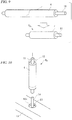
- a mould release is spread on a stationary jig 13, and an uncured sealing resin E1 (for example urethane resin, epoxy resin, ultraviolet curing resin, or the like) is poured onto a recess 13a in the stationary jig 13.
- an uncured sealing resin E1 for example urethane resin, epoxy resin, ultraviolet curing resin, or the like
- a shaft 14 standing upright on the stationary jig 13 is pushed into the hole of the resin pipe 11, so that the unit roll Ru is stood upright on the stationary jig 13.
- the sealing resin E1 is supplied to the one end of the unit roll Ru standing upright on the stationary jig 13. At this time, so that the sealing resin E1 did not adhere to the tacking sheet 12, the tacking sheet 12 is pulled upwards with respect to the hollow fiber sheet 4.
- the tacking sheet 12 is removed from the unit roll Ru and left for a predetermined time.
- the sealing resin E1 cured, and the one ends of the multiplicity of hollow fibers 2 lined up on the one end of the fiber bundle 3 around the resin pipe 11, are bonded to each other, and the holes 2a of the respective hollow fibers 2 that open to the one end of the fiber bundle 3 are blocked (refer to FIG. 3 ).
- the one end of the fiber bundle 3 is bonded to the housing main body 5a.
- a header 5d for supplying sealing resin E2 to the other end of the fiber bundle 3 in a later described centrifugal sealing process.
- the header 5d is finally cut away from the housing main body 5a.
- the unit roll Ru that is fixed to the inside of the housing main body 5a is removed from the stationary jig 13, and the resin pipe 11 is extracted from the unit roll Ru.
- the resin pipe 11 is extracted, only the fiber bundle 3 remained inside of the housing main body 5a, and the central hole 3a is open.
- a mould release is spread on a centrifugal sealing jig 15, and an uncured sealing resin U (for example urethane resin, epoxy resin, ultraviolet curing resin, or the like) is poured onto a recess 15a in the centrifugal sealing jig 15.
- an uncured sealing resin U for example urethane resin, epoxy resin, ultraviolet curing resin, or the like
- the sealing resin U is supplied to the other end of the fiber bundle 3 accommodated in the housing main body 5a standing upright on the centrifugal sealing jig 15.
- the housing main body 5a standing up on the centrifugal sealing jig 15 is left for a predetermined time.
- the housing main body 5a that is bonded to the centrifugal sealing jig 15 is subjected to centrifuging by the centrifugal sealing device.
- sealing resin E2 for example urethane resin, epoxy resin, ultraviolet curing resin, or the like
- a centrifugal force is applied for a predetermined time from the one end of the fiber bundle 3 towards the other end (in the direction of arrow F in the drawing).
- the housing main body 5a accommodating the fiber bundle 3 is cut, and the header 5d, together with the centrifugal sealing jig 15 is cut from the housing main body 5a.
- the holes 2a in the other ends of the respective hollow fibers 2 are open to the other end of the fiber bundle 3 (a condition where the central hole is sealed by the sealing resin E2).
- the first cap 5b is fitted to the one end of the housing main body 5a, and the second 5c is fitted to the other end. If necessary, an adhesive can be filled between the first and second caps 5b and 5c, and the housing main body 5a, to give reinforcement.
- the sheet 4 containing the multiplicity of hollow fibers 2 is wrapped on the resin pipe 11 serving as a temporary core, and retained in a tubular form. After that, the resin pipe 11 is removed from the hollow fiber sheet 4 which is retained in the tubular form.
- a module with just the hollow fiber 2 with a minimal pressure drop produced when the ink flows can be produced without having a core for ensuring rigidity, and serving as a support base for the hollow fibers.
- the sealing resin E1 is supplied to the one end of the hollow fiber sheet 4 of tubular form, and the one ends of the multiplicity of hollow fibers 2 lined up on the one end of the hollow fiber sheet 4 are bonded to each other, and the holes 2a of the respective hollow fibers 2 opening to the one end of the hollow fiber sheet 4 are sealed.
- the central hole 3a parallel with the lengthwise direction of the hollow fiber 2 in the hollow fiber sheet 4 of tubular form.
- the central hole 3a of the hollow fiber sheet 4 in the conventional deaerating hollow fiber module it is ensured by the core serving as the support base. However, even in the deaerating hollow fiber module 1 of the present embodiment which does not have a core, the central hole 3a can be easily ensured by the above described method.
- the sealing resin E2 is supplied to the other end of the hollow fiber sheet 4 of tubular form, and the other ends of the multiplicity of hollow fibers 2 lined up on the other end of the hollow fiber sheet 4 are bonded to each other, and the sealing resin E2 can be filled into the other end of the central hole 3a that opens to the other end of the hollow fiber sheet 4.
- the other end of the central hole 3a of the hollow fiber sheet 4 in the conventional deaerating hollow fiber module, it is closed by the core serving as the support base.
- the core serving as the support base.
- the other end of the central hole 3a can be easily closed.
- the one end of the fiber bundle 3 is statically sealed, and the other end is sealed centrifugally.
- the method of sealing may be either static or centrifugal.
- one end of the unit roll may be sealed centrifugally, and the other end may be sealed statically.
- a plurality of through holes 16 are formed in the wall of the resin pipe 11. Then, by evacuating the inside of the resin pipe 11, the starting end of the hollow fiber sheet 4 is sucked onto the resin pipe 11 through the through holes 16. As a result the hollow fiber sheet 4 can be easily wrapped around the resin pipe 11.
- a plurality of hooks 17 are formed facing in one direction in the circumferential direction on the outer peripheral face of the resin pipe 11. Then, the hollow fiber sheet 4 is caught on the hooks, and the resin pipe 11 is rotated in the direction of the hooks 17 so that the hollow fiber sheet 4 is wrapped around the resin pipe 11. After the sheet has been wrapped, the resin pipe 11 is rotated in the opposite direction so that the resin pipe 11 is gradually extracted from the hollow fiber sheet 4. As a result, the hollow fiber sheet 4 can be easily wrapped on the resin pipe 11. There may be a mechanism whereby the hooks 17 can be mechanically pushed in and out from the outer peripheral face of the resin pipe 11.
- the hooks 17 protrude out from the outer peripheral face of the resin pipe 11, and catch on the hollow fiber sheet 4, and when the resin pipe 11 is extracted from the hollow fiber sheet 4, the hooks 17 are withdrawn to inside the resin pipe 11, so that the resin pipe 11 is removed without the hooks 17 interfering with the hollow fiber sheet 4. Therefore the hollow fiber sheet 4 does not suffer any damage.
- the present invention is a process for manufacturing a deaerating hollow fiber module with no core, and relates to a process for manufacturing a deaerating hollow fiber module comprising the steps of; wrapping a sheet containing a multiplicity of hollow fibers around a temporary core, retaining in tubular form the sheet wrapped around the temporary core; and removing the temporary core from the sheet retained in tubular form.
- a process for manufacturing a deaerating hollow fiber module of the present invention by not having a core for ensuring rigidity and serving as a support base of the hollow fibers, requirements or miniaturization can be satisfied, and also a hollow fiber module for which the pressure loss which occurs at the time of flowing of the product to be processed, is minimized, can be manufactured easily and with high accuracy.
Landscapes
- Chemical & Material Sciences (AREA)
- Chemical Kinetics & Catalysis (AREA)
- Engineering & Computer Science (AREA)
- Manufacturing & Machinery (AREA)
- Separation Using Semi-Permeable Membranes (AREA)
- Degasification And Air Bubble Elimination (AREA)
Claims (1)
- Procédé de fabrication d'un module à fibres creuses pour la désaération (1) comprenant les étapes consistant à :envelopper une feuille (4) contenant une multiplicité de fibres creuses (2) autour d'un coeur temporaire (11) de sorte qu'une forme de la feuille est une forme tubulaire ;maintenir sous forme tubulaire ladite feuille (4) enveloppée autour dudit coeur temporaire (11) ;fournir une résine d'étanchéité (E1) à une extrémité de la feuille (4) qui est maintenue sous une forme tubulaire, couvrir un corps principal de logement (5a) au-dessus de ladite feuille maintenue sous une forme tubulaire, laisser durcir la résine d'étanchéité (E1), et après durcissement, retirer le coeur temporaire (11), ainsi, les ouvertures (2a) des fibres creuses (2) sont fermées, les fibres creuses (2) sont liées les unes aux autres et au corps principal de logement à la première extrémité, et un trou central (3a) est ouvert à une extrémité de la feuille (4) sous une forme tubulaire ;fournir une résine d'étanchéité (U) à l'autre extrémité de la feuille (4) sous une forme tubulaire, laisser durcir la résine d'étanchéité (U), fournir une résine d'étanchéité (E2) via une tête (5d) formée sur le corps principal de logement tout en soumettant la feuille (4) sous forme tubulaire à une centrifugation pour forcer la résine vers l'autre extrémité de la feuille (4) sous forme tubulaire, laisser durcir la résine d'étanchéité (E2), et découper le corps de logement et la feuille (4) sous forme tubulaire, ainsi, les ouvertures (2a) des fibres creuses (2) sont ouvertes, les fibres creuses (2) sont liées les unes aux autres, et le trou central (3a) est fermé à l'autre extrémité de la feuille (4) sous une forme tubulaire.
Applications Claiming Priority (1)
| Application Number | Priority Date | Filing Date | Title |
|---|---|---|---|
| PCT/JP2008/060020 WO2009144813A1 (fr) | 2008-05-30 | 2008-05-30 | Procédé de fabrication d’un module à fibres creuses pour la désaération |
Publications (3)
| Publication Number | Publication Date |
|---|---|
| EP2292318A1 EP2292318A1 (fr) | 2011-03-09 |
| EP2292318A4 EP2292318A4 (fr) | 2012-07-04 |
| EP2292318B1 true EP2292318B1 (fr) | 2019-03-06 |
Family
ID=41376712
Family Applications (1)
| Application Number | Title | Priority Date | Filing Date |
|---|---|---|---|
| EP08777031.9A Active EP2292318B1 (fr) | 2008-05-30 | 2008-05-30 | Procédé de fabrication d'un module à fibres creuses pour la désaération |
Country Status (9)
| Country | Link |
|---|---|
| US (1) | US8449706B2 (fr) |
| EP (1) | EP2292318B1 (fr) |
| JP (1) | JP4730483B2 (fr) |
| KR (1) | KR101465295B1 (fr) |
| CN (1) | CN102046271B (fr) |
| CA (1) | CA2726155C (fr) |
| ES (1) | ES2728399T3 (fr) |
| IL (1) | IL209644A (fr) |
| WO (1) | WO2009144813A1 (fr) |
Families Citing this family (9)
| Publication number | Priority date | Publication date | Assignee | Title |
|---|---|---|---|---|
| CN102580541B (zh) * | 2012-02-15 | 2013-12-18 | 东莞信诺能源科技有限公司 | 可上下叠层连续锁合的导水盘及导水盘组 |
| US9821251B2 (en) | 2013-07-24 | 2017-11-21 | Mitsubishi Chemical Corporation | External-perfusion hollow-fiber membrade module and inkjet printer having said module |
| JP3195924U (ja) | 2014-11-28 | 2015-02-12 | Dic株式会社 | 中空糸脱気モジュール及びインクジェットプリンタ |
| CA2969317C (fr) | 2014-12-24 | 2023-06-13 | Dic Corporation | Module de degazage a fibres creuses et imprimante a jet d'encre |
| ES2961836T3 (es) * | 2014-12-24 | 2024-03-14 | Dainippon Ink & Chemicals | Procedimiento de desgasificación en un módulo de desgasificación de fibra hueca |
| KR101874816B1 (ko) * | 2016-06-29 | 2018-07-05 | 앵스트롬스 주식회사 | 기액접촉 및 탈기를 위한 중공사 맴브레인 필터 |
| JP6854822B2 (ja) * | 2016-08-17 | 2021-04-07 | 三菱ケミカル・クリンスイ株式会社 | 中空糸膜モジュール、脱気給気装置、インクジェットプリンタおよび炭酸泉製造装置 |
| DE102018129165A1 (de) * | 2018-11-20 | 2020-05-20 | UMS Gmbh & Co KG | Gasdruckmessvorrichtung mit Hohlfasermembranbündel |
| WO2023039585A1 (fr) | 2021-09-10 | 2023-03-16 | Pentair, Inc. | Faisceau de membranes de fibres sans noyau |
Family Cites Families (20)
| Publication number | Priority date | Publication date | Assignee | Title |
|---|---|---|---|---|
| JPS5299978A (en) | 1976-02-17 | 1977-08-22 | Mitsubishi Rayon Co Ltd | Fluid separating apparatus used hollow yarn |
| US4210536A (en) * | 1978-09-19 | 1980-07-01 | Albany International Corp. | Hollow filament separatory module |
| JPS6115712A (ja) * | 1984-06-29 | 1986-01-23 | Kanebo Ltd | カ−トリツジフイルタ |
| DE3803693A1 (de) * | 1987-03-10 | 1988-09-22 | Akzo Gmbh | Mehrlagiger hohlfadenwickelkoerper |
| JP2725312B2 (ja) | 1988-10-14 | 1998-03-11 | 大日本インキ化学工業株式会社 | 多孔質中空糸膜型気液接触装置 |
| JPH0517712A (ja) | 1991-07-08 | 1993-01-26 | Seiko Epson Corp | インクジエツト記録用インクの脱気方法 |
| TW223028B (fr) | 1991-12-31 | 1994-05-01 | Hoechst Celanese Corp | |
| US5264171A (en) | 1991-12-31 | 1993-11-23 | Hoechst Celanese Corporation | Method of making spiral-wound hollow fiber membrane fabric cartridges and modules having flow-directing baffles |
| JPH05299978A (ja) | 1992-04-20 | 1993-11-12 | Toshiba Corp | コンパレータ |
| JP3338087B2 (ja) * | 1992-07-31 | 2002-10-28 | エヌオーケー株式会社 | 遠心ポッティング装置 |
| US5284584A (en) | 1992-12-31 | 1994-02-08 | Hoechst Celanese Corporation | Hollow fiber membrane fabric - containing cartridges and modules having solvent-resistant thermoplastic tube sheets, and methods for making the same |
| JPH0788304A (ja) * | 1993-09-21 | 1995-04-04 | Mitsubishi Rayon Co Ltd | 溶存ガス除去およびガス給気モジュール |
| US6623637B1 (en) * | 1996-12-24 | 2003-09-23 | Kitz Corporation | Hollow-fiber membrane module |
| JPH10298470A (ja) | 1997-04-30 | 1998-11-10 | Mitsubishi Rayon Co Ltd | インクの脱気方法及びインク脱気装置 |
| US6558450B2 (en) | 2001-03-22 | 2003-05-06 | Celgard Inc. | Method for debubbling an ink |
| US20020168491A1 (en) | 2001-05-08 | 2002-11-14 | Runkle Charles J. | Hollow fiber membrane contactor and method for making same |
| EP1468437A2 (fr) * | 2001-09-24 | 2004-10-20 | FEI Company | Appareil de manipulation electrostatique |
| NL1019374C2 (nl) | 2001-11-15 | 2003-05-16 | Norit Holding N V | Werkwijze voor het vervaardigen van een filtermodule, een dergelijke al dan niet in een filtersysteem opgenomen filtermodule. |
| WO2007040036A1 (fr) * | 2005-09-30 | 2007-04-12 | Kureha Corporation | Article de fibres creuses de type en grille de bambou, procede de production d'un faisceau de fibres creuses, module de membrane de fibres creuses tubulaires et module de membrane de fibres creuses de type a immersion |
| US20090156875A1 (en) | 2006-04-04 | 2009-06-18 | Takafumi Tomioka | Methane separation method, methane separation apparatus, and methane utilization system |
-
2008
- 2008-05-30 WO PCT/JP2008/060020 patent/WO2009144813A1/fr not_active Ceased
- 2008-05-30 EP EP08777031.9A patent/EP2292318B1/fr active Active
- 2008-05-30 US US12/736,975 patent/US8449706B2/en active Active
- 2008-05-30 CA CA2726155A patent/CA2726155C/fr active Active
- 2008-05-30 ES ES08777031T patent/ES2728399T3/es active Active
- 2008-05-30 CN CN200880129512.0A patent/CN102046271B/zh active Active
- 2008-05-30 JP JP2010514306A patent/JP4730483B2/ja active Active
- 2008-05-30 KR KR1020107028031A patent/KR101465295B1/ko active Active
-
2010
- 2010-11-30 IL IL209644A patent/IL209644A/en active IP Right Grant
Non-Patent Citations (1)
| Title |
|---|
| None * |
Also Published As
| Publication number | Publication date |
|---|---|
| US8449706B2 (en) | 2013-05-28 |
| ES2728399T3 (es) | 2019-10-24 |
| US20110146891A1 (en) | 2011-06-23 |
| EP2292318A1 (fr) | 2011-03-09 |
| JP4730483B2 (ja) | 2011-07-20 |
| IL209644A0 (en) | 2011-02-28 |
| KR101465295B1 (ko) | 2014-11-26 |
| WO2009144813A1 (fr) | 2009-12-03 |
| EP2292318A4 (fr) | 2012-07-04 |
| CA2726155A1 (fr) | 2009-12-03 |
| CA2726155C (fr) | 2018-09-04 |
| IL209644A (en) | 2015-10-29 |
| HK1153422A1 (zh) | 2012-03-30 |
| CN102046271B (zh) | 2016-01-06 |
| KR20110011686A (ko) | 2011-02-08 |
| JPWO2009144813A1 (ja) | 2011-09-29 |
| CN102046271A (zh) | 2011-05-04 |
Similar Documents
| Publication | Publication Date | Title |
|---|---|---|
| EP2292318B1 (fr) | Procédé de fabrication d'un module à fibres creuses pour la désaération | |
| US6623637B1 (en) | Hollow-fiber membrane module | |
| JP6788014B2 (ja) | 外部潅流型中空糸膜モジュール | |
| CN104394966B (zh) | 中空丝膜模组 | |
| JP7683745B2 (ja) | 脱気モジュール及び液体の脱気方法 | |
| EP2832387B1 (fr) | Procédé de fabrication pour un instrument médical, instrument médical | |
| EP2030672A2 (fr) | Membrane à fibres creuses et son procédé de fabrication | |
| TW201632244A (zh) | 具有多褶包裝之使用點或分配點過濾器 | |
| JPH11244607A (ja) | 薬液の脱気方法及び脱気装置 | |
| JP7662059B2 (ja) | 脱気モジュール及び液体の脱気方法 | |
| TWI435758B (zh) | 排氣用中空絲模組之製造方法 | |
| JP6937175B2 (ja) | 中空糸膜濾過装置及びその洗浄方法 | |
| HK1153422B (en) | Process for manufacturing deaerating hollow fiber module | |
| TW202545614A (zh) | 脫氣模組及液體之脫氣方法 | |
| WO2026094775A1 (fr) | Procédé de fabrication d'élément de membrane à fibres creuses, élément de membrane à fibres creuses et module à membrane à fibres creuses | |
| JP2006082035A (ja) | 中空糸膜モジュールの製造方法 |
Legal Events
| Date | Code | Title | Description |
|---|---|---|---|
| PUAI | Public reference made under article 153(3) epc to a published international application that has entered the european phase |
Free format text: ORIGINAL CODE: 0009012 |
|
| 17P | Request for examination filed |
Effective date: 20101206 |
|
| AK | Designated contracting states |
Kind code of ref document: A1 Designated state(s): AT BE BG CH CY CZ DE DK EE ES FI FR GB GR HR HU IE IS IT LI LT LU LV MC MT NL NO PL PT RO SE SI SK TR |
|
| AX | Request for extension of the european patent |
Extension state: AL BA MK RS |
|
| DAX | Request for extension of the european patent (deleted) | ||
| A4 | Supplementary search report drawn up and despatched |
Effective date: 20120601 |
|
| RIC1 | Information provided on ipc code assigned before grant |
Ipc: B01D 19/00 20060101ALI20120525BHEP Ipc: B01D 63/02 20060101AFI20120525BHEP |
|
| STAA | Information on the status of an ep patent application or granted ep patent |
Free format text: STATUS: EXAMINATION IS IN PROGRESS |
|
| 17Q | First examination report despatched |
Effective date: 20170817 |
|
| GRAP | Despatch of communication of intention to grant a patent |
Free format text: ORIGINAL CODE: EPIDOSNIGR1 |
|
| STAA | Information on the status of an ep patent application or granted ep patent |
Free format text: STATUS: GRANT OF PATENT IS INTENDED |
|
| INTG | Intention to grant announced |
Effective date: 20180608 |
|
| GRAJ | Information related to disapproval of communication of intention to grant by the applicant or resumption of examination proceedings by the epo deleted |
Free format text: ORIGINAL CODE: EPIDOSDIGR1 |
|
| STAA | Information on the status of an ep patent application or granted ep patent |
Free format text: STATUS: EXAMINATION IS IN PROGRESS |
|
| GRAP | Despatch of communication of intention to grant a patent |
Free format text: ORIGINAL CODE: EPIDOSNIGR1 |
|
| STAA | Information on the status of an ep patent application or granted ep patent |
Free format text: STATUS: GRANT OF PATENT IS INTENDED |
|
| INTG | Intention to grant announced |
Effective date: 20180904 |
|
| GRAS | Grant fee paid |
Free format text: ORIGINAL CODE: EPIDOSNIGR3 |
|
| GRAJ | Information related to disapproval of communication of intention to grant by the applicant or resumption of examination proceedings by the epo deleted |
Free format text: ORIGINAL CODE: EPIDOSDIGR1 |
|
| GRAL | Information related to payment of fee for publishing/printing deleted |
Free format text: ORIGINAL CODE: EPIDOSDIGR3 |
|
| STAA | Information on the status of an ep patent application or granted ep patent |
Free format text: STATUS: EXAMINATION IS IN PROGRESS |
|
| GRAR | Information related to intention to grant a patent recorded |
Free format text: ORIGINAL CODE: EPIDOSNIGR71 |
|
| STAA | Information on the status of an ep patent application or granted ep patent |
Free format text: STATUS: GRANT OF PATENT IS INTENDED |
|
| GRAA | (expected) grant |
Free format text: ORIGINAL CODE: 0009210 |
|
| STAA | Information on the status of an ep patent application or granted ep patent |
Free format text: STATUS: THE PATENT HAS BEEN GRANTED |
|
| INTC | Intention to grant announced (deleted) | ||
| INTG | Intention to grant announced |
Effective date: 20190122 |
|
| AK | Designated contracting states |
Kind code of ref document: B1 Designated state(s): AT BE BG CH CY CZ DE DK EE ES FI FR GB GR HR HU IE IS IT LI LT LU LV MC MT NL NO PL PT RO SE SI SK TR |
|
| REG | Reference to a national code |
Ref country code: GB Ref legal event code: FG4D |
|
| REG | Reference to a national code |
Ref country code: CH Ref legal event code: EP Ref country code: AT Ref legal event code: REF Ref document number: 1103800 Country of ref document: AT Kind code of ref document: T Effective date: 20190315 |
|
| REG | Reference to a national code |
Ref country code: DE Ref legal event code: R096 Ref document number: 602008059248 Country of ref document: DE |
|
| REG | Reference to a national code |
Ref country code: IE Ref legal event code: FG4D |
|
| REG | Reference to a national code |
Ref country code: NL Ref legal event code: MP Effective date: 20190306 |
|
| REG | Reference to a national code |
Ref country code: LT Ref legal event code: MG4D |
|
| PG25 | Lapsed in a contracting state [announced via postgrant information from national office to epo] |
Ref country code: FI Free format text: LAPSE BECAUSE OF FAILURE TO SUBMIT A TRANSLATION OF THE DESCRIPTION OR TO PAY THE FEE WITHIN THE PRESCRIBED TIME-LIMIT Effective date: 20190306 Ref country code: LT Free format text: LAPSE BECAUSE OF FAILURE TO SUBMIT A TRANSLATION OF THE DESCRIPTION OR TO PAY THE FEE WITHIN THE PRESCRIBED TIME-LIMIT Effective date: 20190306 Ref country code: NO Free format text: LAPSE BECAUSE OF FAILURE TO SUBMIT A TRANSLATION OF THE DESCRIPTION OR TO PAY THE FEE WITHIN THE PRESCRIBED TIME-LIMIT Effective date: 20190606 Ref country code: SE Free format text: LAPSE BECAUSE OF FAILURE TO SUBMIT A TRANSLATION OF THE DESCRIPTION OR TO PAY THE FEE WITHIN THE PRESCRIBED TIME-LIMIT Effective date: 20190306 |
|
| PG25 | Lapsed in a contracting state [announced via postgrant information from national office to epo] |
Ref country code: LV Free format text: LAPSE BECAUSE OF FAILURE TO SUBMIT A TRANSLATION OF THE DESCRIPTION OR TO PAY THE FEE WITHIN THE PRESCRIBED TIME-LIMIT Effective date: 20190306 Ref country code: HR Free format text: LAPSE BECAUSE OF FAILURE TO SUBMIT A TRANSLATION OF THE DESCRIPTION OR TO PAY THE FEE WITHIN THE PRESCRIBED TIME-LIMIT Effective date: 20190306 Ref country code: GR Free format text: LAPSE BECAUSE OF FAILURE TO SUBMIT A TRANSLATION OF THE DESCRIPTION OR TO PAY THE FEE WITHIN THE PRESCRIBED TIME-LIMIT Effective date: 20190607 Ref country code: BG Free format text: LAPSE BECAUSE OF FAILURE TO SUBMIT A TRANSLATION OF THE DESCRIPTION OR TO PAY THE FEE WITHIN THE PRESCRIBED TIME-LIMIT Effective date: 20190606 Ref country code: NL Free format text: LAPSE BECAUSE OF FAILURE TO SUBMIT A TRANSLATION OF THE DESCRIPTION OR TO PAY THE FEE WITHIN THE PRESCRIBED TIME-LIMIT Effective date: 20190306 |
|
| REG | Reference to a national code |
Ref country code: ES Ref legal event code: FG2A Ref document number: 2728399 Country of ref document: ES Kind code of ref document: T3 Effective date: 20191024 |
|
| PG25 | Lapsed in a contracting state [announced via postgrant information from national office to epo] |
Ref country code: EE Free format text: LAPSE BECAUSE OF FAILURE TO SUBMIT A TRANSLATION OF THE DESCRIPTION OR TO PAY THE FEE WITHIN THE PRESCRIBED TIME-LIMIT Effective date: 20190306 Ref country code: PT Free format text: LAPSE BECAUSE OF FAILURE TO SUBMIT A TRANSLATION OF THE DESCRIPTION OR TO PAY THE FEE WITHIN THE PRESCRIBED TIME-LIMIT Effective date: 20190706 Ref country code: CZ Free format text: LAPSE BECAUSE OF FAILURE TO SUBMIT A TRANSLATION OF THE DESCRIPTION OR TO PAY THE FEE WITHIN THE PRESCRIBED TIME-LIMIT Effective date: 20190306 Ref country code: RO Free format text: LAPSE BECAUSE OF FAILURE TO SUBMIT A TRANSLATION OF THE DESCRIPTION OR TO PAY THE FEE WITHIN THE PRESCRIBED TIME-LIMIT Effective date: 20190306 Ref country code: SK Free format text: LAPSE BECAUSE OF FAILURE TO SUBMIT A TRANSLATION OF THE DESCRIPTION OR TO PAY THE FEE WITHIN THE PRESCRIBED TIME-LIMIT Effective date: 20190306 |
|
| PG25 | Lapsed in a contracting state [announced via postgrant information from national office to epo] |
Ref country code: PL Free format text: LAPSE BECAUSE OF FAILURE TO SUBMIT A TRANSLATION OF THE DESCRIPTION OR TO PAY THE FEE WITHIN THE PRESCRIBED TIME-LIMIT Effective date: 20190306 |
|
| REG | Reference to a national code |
Ref country code: DE Ref legal event code: R097 Ref document number: 602008059248 Country of ref document: DE |
|
| REG | Reference to a national code |
Ref country code: CH Ref legal event code: PL |
|
| PG25 | Lapsed in a contracting state [announced via postgrant information from national office to epo] |
Ref country code: IS Free format text: LAPSE BECAUSE OF FAILURE TO SUBMIT A TRANSLATION OF THE DESCRIPTION OR TO PAY THE FEE WITHIN THE PRESCRIBED TIME-LIMIT Effective date: 20190706 |
|
| PLBE | No opposition filed within time limit |
Free format text: ORIGINAL CODE: 0009261 |
|
| STAA | Information on the status of an ep patent application or granted ep patent |
Free format text: STATUS: NO OPPOSITION FILED WITHIN TIME LIMIT |
|
| PG25 | Lapsed in a contracting state [announced via postgrant information from national office to epo] |
Ref country code: DK Free format text: LAPSE BECAUSE OF FAILURE TO SUBMIT A TRANSLATION OF THE DESCRIPTION OR TO PAY THE FEE WITHIN THE PRESCRIBED TIME-LIMIT Effective date: 20190306 Ref country code: CH Free format text: LAPSE BECAUSE OF NON-PAYMENT OF DUE FEES Effective date: 20190531 Ref country code: MC Free format text: LAPSE BECAUSE OF FAILURE TO SUBMIT A TRANSLATION OF THE DESCRIPTION OR TO PAY THE FEE WITHIN THE PRESCRIBED TIME-LIMIT Effective date: 20190306 Ref country code: LI Free format text: LAPSE BECAUSE OF NON-PAYMENT OF DUE FEES Effective date: 20190531 |
|
| 26N | No opposition filed |
Effective date: 20191209 |
|
| PG25 | Lapsed in a contracting state [announced via postgrant information from national office to epo] |
Ref country code: SI Free format text: LAPSE BECAUSE OF FAILURE TO SUBMIT A TRANSLATION OF THE DESCRIPTION OR TO PAY THE FEE WITHIN THE PRESCRIBED TIME-LIMIT Effective date: 20190306 Ref country code: LU Free format text: LAPSE BECAUSE OF NON-PAYMENT OF DUE FEES Effective date: 20190530 |
|
| PG25 | Lapsed in a contracting state [announced via postgrant information from national office to epo] |
Ref country code: TR Free format text: LAPSE BECAUSE OF FAILURE TO SUBMIT A TRANSLATION OF THE DESCRIPTION OR TO PAY THE FEE WITHIN THE PRESCRIBED TIME-LIMIT Effective date: 20190306 |
|
| PG25 | Lapsed in a contracting state [announced via postgrant information from national office to epo] |
Ref country code: IE Free format text: LAPSE BECAUSE OF NON-PAYMENT OF DUE FEES Effective date: 20190530 |
|
| PG25 | Lapsed in a contracting state [announced via postgrant information from national office to epo] |
Ref country code: CY Free format text: LAPSE BECAUSE OF FAILURE TO SUBMIT A TRANSLATION OF THE DESCRIPTION OR TO PAY THE FEE WITHIN THE PRESCRIBED TIME-LIMIT Effective date: 20190306 |
|
| PG25 | Lapsed in a contracting state [announced via postgrant information from national office to epo] |
Ref country code: MT Free format text: LAPSE BECAUSE OF FAILURE TO SUBMIT A TRANSLATION OF THE DESCRIPTION OR TO PAY THE FEE WITHIN THE PRESCRIBED TIME-LIMIT Effective date: 20190306 Ref country code: HU Free format text: LAPSE BECAUSE OF FAILURE TO SUBMIT A TRANSLATION OF THE DESCRIPTION OR TO PAY THE FEE WITHIN THE PRESCRIBED TIME-LIMIT; INVALID AB INITIO Effective date: 20080530 |
|
| REG | Reference to a national code |
Ref country code: AT Ref legal event code: UEP Ref document number: 1103800 Country of ref document: AT Kind code of ref document: T Effective date: 20190306 |
|
| P01 | Opt-out of the competence of the unified patent court (upc) registered |
Effective date: 20230324 |
|
| PGFP | Annual fee paid to national office [announced via postgrant information from national office to epo] |
Ref country code: DE Payment date: 20250423 Year of fee payment: 18 |
|
| PGFP | Annual fee paid to national office [announced via postgrant information from national office to epo] |
Ref country code: ES Payment date: 20250602 Year of fee payment: 18 |
|
| PGFP | Annual fee paid to national office [announced via postgrant information from national office to epo] |
Ref country code: IT Payment date: 20250423 Year of fee payment: 18 Ref country code: BE Payment date: 20250423 Year of fee payment: 18 |
|
| PGFP | Annual fee paid to national office [announced via postgrant information from national office to epo] |
Ref country code: FR Payment date: 20250423 Year of fee payment: 18 |
|
| PGFP | Annual fee paid to national office [announced via postgrant information from national office to epo] |
Ref country code: AT Payment date: 20250424 Year of fee payment: 18 |
|
| PGFP | Annual fee paid to national office [announced via postgrant information from national office to epo] |
Ref country code: GB Payment date: 20260317 Year of fee payment: 19 |