EP2292372A2 - Procédé de création d'un trou en utilisant divers réglages laser - Google Patents
Procédé de création d'un trou en utilisant divers réglages laser Download PDFInfo
- Publication number
- EP2292372A2 EP2292372A2 EP10002655A EP10002655A EP2292372A2 EP 2292372 A2 EP2292372 A2 EP 2292372A2 EP 10002655 A EP10002655 A EP 10002655A EP 10002655 A EP10002655 A EP 10002655A EP 2292372 A2 EP2292372 A2 EP 2292372A2
- Authority
- EP
- European Patent Office
- Prior art keywords
- remainder
- laser
- diffuser
- laser beam
- iii
- Prior art date
- Legal status (The legal status is an assumption and is not a legal conclusion. Google has not performed a legal analysis and makes no representation as to the accuracy of the status listed.)
- Granted
Links
- 238000000034 method Methods 0.000 title claims abstract description 28
- 239000000758 substrate Substances 0.000 claims abstract description 17
- 238000004519 manufacturing process Methods 0.000 claims description 22
- 238000001816 cooling Methods 0.000 claims description 19
- 239000010410 layer Substances 0.000 description 13
- PXHVJJICTQNCMI-UHFFFAOYSA-N Nickel Chemical compound [Ni] PXHVJJICTQNCMI-UHFFFAOYSA-N 0.000 description 8
- 239000000463 material Substances 0.000 description 8
- 239000012720 thermal barrier coating Substances 0.000 description 7
- 238000000576 coating method Methods 0.000 description 6
- 238000002485 combustion reaction Methods 0.000 description 6
- 229910000601 superalloy Inorganic materials 0.000 description 6
- 229910017052 cobalt Inorganic materials 0.000 description 5
- 239000010941 cobalt Substances 0.000 description 5
- GUTLYIVDDKVIGB-UHFFFAOYSA-N cobalt atom Chemical compound [Co] GUTLYIVDDKVIGB-UHFFFAOYSA-N 0.000 description 5
- 239000013078 crystal Substances 0.000 description 5
- 238000005260 corrosion Methods 0.000 description 3
- 230000003993 interaction Effects 0.000 description 3
- 229910052759 nickel Inorganic materials 0.000 description 3
- 238000007711 solidification Methods 0.000 description 3
- 230000008023 solidification Effects 0.000 description 3
- XEEYBQQBJWHFJM-UHFFFAOYSA-N Iron Chemical compound [Fe] XEEYBQQBJWHFJM-UHFFFAOYSA-N 0.000 description 2
- 229910045601 alloy Inorganic materials 0.000 description 2
- 239000000956 alloy Substances 0.000 description 2
- BRPQOXSCLDDYGP-UHFFFAOYSA-N calcium oxide Chemical compound [O-2].[Ca+2] BRPQOXSCLDDYGP-UHFFFAOYSA-N 0.000 description 2
- 239000000292 calcium oxide Substances 0.000 description 2
- ODINCKMPIJJUCX-UHFFFAOYSA-N calcium oxide Inorganic materials [Ca]=O ODINCKMPIJJUCX-UHFFFAOYSA-N 0.000 description 2
- 238000005266 casting Methods 0.000 description 2
- 239000002826 coolant Substances 0.000 description 2
- 230000007797 corrosion Effects 0.000 description 2
- 238000005566 electron beam evaporation Methods 0.000 description 2
- 229910052735 hafnium Inorganic materials 0.000 description 2
- VBJZVLUMGGDVMO-UHFFFAOYSA-N hafnium atom Chemical compound [Hf] VBJZVLUMGGDVMO-UHFFFAOYSA-N 0.000 description 2
- 239000000395 magnesium oxide Substances 0.000 description 2
- CPLXHLVBOLITMK-UHFFFAOYSA-N magnesium oxide Inorganic materials [Mg]=O CPLXHLVBOLITMK-UHFFFAOYSA-N 0.000 description 2
- AXZKOIWUVFPNLO-UHFFFAOYSA-N magnesium;oxygen(2-) Chemical compound [O-2].[Mg+2] AXZKOIWUVFPNLO-UHFFFAOYSA-N 0.000 description 2
- 239000000203 mixture Substances 0.000 description 2
- 230000003647 oxidation Effects 0.000 description 2
- 238000007254 oxidation reaction Methods 0.000 description 2
- 230000008569 process Effects 0.000 description 2
- 229910052710 silicon Inorganic materials 0.000 description 2
- 239000010703 silicon Substances 0.000 description 2
- 239000007787 solid Substances 0.000 description 2
- 230000007704 transition Effects 0.000 description 2
- 229910052727 yttrium Inorganic materials 0.000 description 2
- VWQVUPCCIRVNHF-UHFFFAOYSA-N yttrium atom Chemical compound [Y] VWQVUPCCIRVNHF-UHFFFAOYSA-N 0.000 description 2
- YPFNIPKMNMDDDB-UHFFFAOYSA-K 2-[2-[bis(carboxylatomethyl)amino]ethyl-(2-hydroxyethyl)amino]acetate;iron(3+) Chemical compound [Fe+3].OCCN(CC([O-])=O)CCN(CC([O-])=O)CC([O-])=O YPFNIPKMNMDDDB-UHFFFAOYSA-K 0.000 description 1
- 241000191291 Abies alba Species 0.000 description 1
- 239000008186 active pharmaceutical agent Substances 0.000 description 1
- 230000001154 acute effect Effects 0.000 description 1
- 239000002318 adhesion promoter Substances 0.000 description 1
- 239000000919 ceramic Substances 0.000 description 1
- 230000008859 change Effects 0.000 description 1
- 239000011248 coating agent Substances 0.000 description 1
- 230000001419 dependent effect Effects 0.000 description 1
- 238000010894 electron beam technology Methods 0.000 description 1
- 239000012530 fluid Substances 0.000 description 1
- 238000005242 forging Methods 0.000 description 1
- 239000000446 fuel Substances 0.000 description 1
- 238000000608 laser ablation Methods 0.000 description 1
- 239000007788 liquid Substances 0.000 description 1
- 238000003754 machining Methods 0.000 description 1
- 239000000155 melt Substances 0.000 description 1
- 229910001092 metal group alloy Inorganic materials 0.000 description 1
- 239000007769 metal material Substances 0.000 description 1
- 238000003801 milling Methods 0.000 description 1
- TWNQGVIAIRXVLR-UHFFFAOYSA-N oxo(oxoalumanyloxy)alumane Chemical compound O=[Al]O[Al]=O TWNQGVIAIRXVLR-UHFFFAOYSA-N 0.000 description 1
- SIWVEOZUMHYXCS-UHFFFAOYSA-N oxo(oxoyttriooxy)yttrium Chemical compound O=[Y]O[Y]=O SIWVEOZUMHYXCS-UHFFFAOYSA-N 0.000 description 1
- 238000007750 plasma spraying Methods 0.000 description 1
- 238000010248 power generation Methods 0.000 description 1
- 239000011253 protective coating Substances 0.000 description 1
- 230000001681 protective effect Effects 0.000 description 1
- 239000011241 protective layer Substances 0.000 description 1
- 229910052761 rare earth metal Inorganic materials 0.000 description 1
- 150000002910 rare earth metals Chemical class 0.000 description 1
- 238000009419 refurbishment Methods 0.000 description 1
- 238000005488 sandblasting Methods 0.000 description 1
- 229910052706 scandium Inorganic materials 0.000 description 1
- SIXSYDAISGFNSX-UHFFFAOYSA-N scandium atom Chemical compound [Sc] SIXSYDAISGFNSX-UHFFFAOYSA-N 0.000 description 1
- 230000035939 shock Effects 0.000 description 1
- 230000035882 stress Effects 0.000 description 1
- 239000000126 substance Substances 0.000 description 1
- 230000008646 thermal stress Effects 0.000 description 1
- RUDFQVOCFDJEEF-UHFFFAOYSA-N yttrium(III) oxide Inorganic materials [O-2].[O-2].[O-2].[Y+3].[Y+3] RUDFQVOCFDJEEF-UHFFFAOYSA-N 0.000 description 1
Images


Classifications
-
- B—PERFORMING OPERATIONS; TRANSPORTING
- B23—MACHINE TOOLS; METAL-WORKING NOT OTHERWISE PROVIDED FOR
- B23K—SOLDERING OR UNSOLDERING; WELDING; CLADDING OR PLATING BY SOLDERING OR WELDING; CUTTING BY APPLYING HEAT LOCALLY, e.g. FLAME CUTTING; WORKING BY LASER BEAM
- B23K26/00—Working by laser beam, e.g. welding, cutting or boring
- B23K26/36—Removing material
- B23K26/38—Removing material by boring or cutting
- B23K26/382—Removing material by boring or cutting by boring
- B23K26/389—Removing material by boring or cutting by boring of fluid openings, e.g. nozzles, jets
-
- B—PERFORMING OPERATIONS; TRANSPORTING
- B23—MACHINE TOOLS; METAL-WORKING NOT OTHERWISE PROVIDED FOR
- B23K—SOLDERING OR UNSOLDERING; WELDING; CLADDING OR PLATING BY SOLDERING OR WELDING; CUTTING BY APPLYING HEAT LOCALLY, e.g. FLAME CUTTING; WORKING BY LASER BEAM
- B23K26/00—Working by laser beam, e.g. welding, cutting or boring
- B23K26/02—Positioning or observing the workpiece, e.g. with respect to the point of impact; Aligning, aiming or focusing the laser beam
- B23K26/06—Shaping the laser beam, e.g. by masks or multi-focusing
- B23K26/062—Shaping the laser beam, e.g. by masks or multi-focusing by direct control of the laser beam
- B23K26/0622—Shaping the laser beam, e.g. by masks or multi-focusing by direct control of the laser beam by shaping pulses
Definitions
- the invention relates to a method for producing a hole in which the angular position of the laser relative to the substrate is changed discontinuously during processing.
- the use of the laser to make holes in substrates is known in which the laser is moved across the surface.
- the EP 0 950 463 A1 discloses that a laser beam rotates about an axis to first make the diffuser of a film cooling hole.
- the basic idea of the invention is therefore to divide the total volume of the hole to be produced into partial volumes and to form these in individual production steps. First, an inner portion is generated. A remainder remains to form the diffuser of the hole. The component material of a few individual partial volumes of this remainder is removed by traversing in each case one lateral flank of the bore with the laser beam.
- the laser beam is preferably aligned so that it encloses an angle of greater than 8 ° with the worn flank. Since the laser beam is not directed close to and parallel to the already formed flank of the bore on the component surface during the production of the bore, it is impossible that there is an impermissible interaction between the laser beam and the flank. Furthermore, the division of the total volume of the bore into several sub-volumes allows complex bore geometries to be formed.
- the laser beam is aligned so that it with the trailing edge an angle greater than 10 ° and less than 90 °, preferably greater than 15 ° and less than 80 ° and more preferably greater than 20 ° and smaller 60 °. Particularly preferred is an angle of 9 °.
- a laser beam with variable pulse width can be used become.
- the pulse width can be in the range from 50ns to 800ns, preferably from 70ns to 600ns and especially from 200ns to 500ns. Particularly preferred is a pulse width of 400ns.
- the component material can be evaporated very quickly. This is particularly advantageous for the manufacture of the diffuser.
- a laser beam with a frequency in the range of 20 kHz to 40 kHz, preferably from 25 kHz to 35 kHz and in particular from 28 kHz to 32 kHz can be directed to the component surface. This is particularly advantageous for the manufacture of the diffuser.
- a preferred embodiment of the invention provides to manufacture a bore in a turbine component, in particular in a turbine blade.
- the bore may in particular be a complete cooling air bore or a diffuser opening of a cooling air bore.
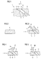
- FIG. 1 a hole 1 in a substrate 4 is shown.
- the substrate 4 is a nickel- or cobalt-based superalloy, in particular in turbine components such as turbine blades 120, 130 FIG. 12 ,
- the hole 1 is continuous (no blind hole).
- the film cooling hole 1 is overflowed in an overflow direction 9 of a hot gas.
- An outflow direction 8 of a cooling medium from the film cooling hole 1 and the overflow 9 form an acute angle with each other.
- the film cooling hole 1 has at least two differently shaped sections 7, 10, in particular it has only two sections 7, 10.
- the first portion is an inner portion 7 which is preferably cylindrical or rotationally symmetrical in cross section or preferably has at least one constant cross section in an outflow direction 8.
- a perpendicular 19 on the inner surface 17a intersects an opposing portion 15 in the substrate 4 on the surface 12th
- a laser 22 is used by way of example as a processing machine.
- the method begins with the provision of the substrate 4 (FIG. Fig. 2 ), which is then processed with a laser 22 or electron beam source in a first angular position (I), preferably the laser position (I).
- the angle of the angular positions I, II, III is defined by a middle line of a laser beam 25 and the surface 12 around the film cooling hole 1.
- the inner portion 7 is produced from the surface 12 to the opposite inner surface 13 of the substrate 4 (in the case of turbine blades in the cavity) ( Fig. 3 ).
- the laser 22 does not have to be moved.
- a remainder 16 remains in the hole 1 to be produced in order to finish the diffuser 10 ( Fig. 3 ).
- the inner portion 7 is completed.
- a first partial volume of the remainder 16 in a further step ( Fig. 4 ) and in a second laser position II, which is different from the first laser position I, a first partial volume of the remainder 16, a left partial volume 28 (FIG. Fig. 6-9 ) as the first portion of the still to be removed remainder 16 for the diffuser 10 removed.
- the angular position of the laser 22 relative to the surface of the flank has changed in the position II compared to the angular position I.
- the laser 22 is moved, preferably via the right flank 17b of the remainder 16, until a left flank 17a of the diffuser 10 is exposed.
- the method of the laser 22 does not represent any other angular position.
- laser parameters such as pulse lengths are preferably used as in the first laser position I.
- the angular position III of the laser 22 is different from the position II, in particular also from the angular position I.
- the angular positions I, II, III of the laser 22 preferably correspond to the partial steps.
- the production or the change of the laser positions I, II, III of the laser 22 relative to the substrate 4 is due to the fact that a laser 22 can not be used if a cut surface is to be made parallel to the laser beam direction, since the laser beam cone scatters 10 °, wherein the cone must not overlap with a final contour of the one area to be produced.
- the complex process steps give outstanding results as compared to using the laser / lasers in a single center position of II and III or only in position I.
- two lasers may also preferably be used if necessary, in particular for the manufacture of the diffuser 10, in which other parameters are preferably used for the second laser, so that the lasers 22 have different performance characteristics (power, pulse duration, frequency, .. .) exhibit.
- the laser beam is aligned in such a way that it encloses an angle of greater than 10 ° and less than 90 °, preferably greater than 15 ° and less than 80 °, and particularly preferably greater than 20 ° and less than 60 °, with the trailing edge. Particularly preferred is an angle of 9 °.
- a pulsed laser beam In this case, a laser beam with variable pulse width can be used.
- the pulse width can be in the range from 50ns to 800ns, preferably from 70ns to 600ns and especially from 200ns to 500ns. Particularly preferred is a pulse width of 400ns.
- the component material can be evaporated very quickly. This is particularly advantageous for the production of the diffuser 10, ie in the angular positions II, III.
- these pulse widths are not used in the angular position I.
- a laser beam with a frequency in the range of 20 kHz to 40 kHz, preferably from 25 kHz to 35 kHz and in particular from 28 kHz to 32 kHz can be directed to the component surface.
- This is particularly advantageous for the production of the diffuser 10, ie in the angular positions II, III.
- these frequencies are not used in the angular position I.
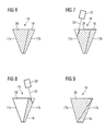
- FIG. 6 shows the rest 16 after FIG. 3 , wherein the remainder 16 is indicated by right and left laterally delimiting flanks 17a and 17b with dashed lines. Also with a dashed line, the total volume of the residue 16 to be removed is divided into a left 28 and a right 18 partial volume.
- the production of the left partial volume 28 is in the FIG. 7 shown and the FIG. 8 illustrates that of the right partial volume 18.
- a laser beam 25 is emitted by a laser 22 onto the component surface.
- the laser 22 is aligned so that the laser beam 25 with the left flank 17a forms an angle preferably greater than 5 ° and first encounters the immediately adjacent to the left flank 17 region of the left part of the volume 13, where it evaporates a portion of the component material.
- the laser beam 25 is further directed to the component surface until it reaches the left flank 17a. Then, the laser 22 is moved to the right in the drawing so that the laser beam 25 impinges on still existing in the sub-volume 13 component material, which in turn is evaporated to the left flank 17 a. In this way, the entire edge 17a of the partial volume 13 is traversed with the laser beam 25.
- the laser 22 is rotated counterclockwise and aligned so that the laser beam 25 with the right flank 17 b forms an angle greater than 8 ° and initially on the right Flank 17b adjacent region of the right sub-volume 18 impinges, where it evaporates a portion of the component material. Subsequently, in the manner already described, the right flank 17b is traversed with the laser beam 25, in order also to remove the right subvolume 18 (FIG. Fig. 8 ).
- FIG. 9 shows the rest 16 of the FIG. 2 in a schematic representation, wherein here an alternative hole geometry is indicated, which is defined by laterally delimiting flanks 17a and 17b.
- this alternative bore geometry the partial volumes 28 and 18 are arranged one above the other, wherein the partial volume 18 preferably adjoins the outer surface 12 of the component 1 with the tip.
- the production of the film cooling hole can also be carried out as described above if a metallic adhesion promoter layer, preferably of the MCrAlY type, is present on the substrate 4 and / or a ceramic layer is present on an MCrAlY layer or on the substrate 4.
- a metallic adhesion promoter layer preferably of the MCrAlY type
- the FIG. 10 shows by way of example a gas turbine 100 in a longitudinal partial section.
- the gas turbine 100 has inside a rotatably mounted about a rotation axis 102 rotor 103 with a shaft 101, which is also referred to as a turbine runner.
- a compressor 105 for example, a toroidal combustion chamber 110, in particular annular combustion chamber, with a plurality of coaxially arranged burners 107, a turbine 108 and the exhaust housing 109th
- the annular combustion chamber 110 communicates with an annular annular hot gas channel 111, for example.
- Each turbine stage 112 is formed, for example, from two blade rings. As seen in the direction of flow of a working medium 113, in the hot gas channel 111 of a row of guide vanes 115, a series 125 formed of rotor blades 120 follows.
- the guide vanes 130 are fastened to an inner housing 138 of a stator 143, whereas the moving blades 120 of a row 125 are attached to the rotor 103 by means of a turbine disk 133, for example. Coupled to the rotor 103 is a generator or work machine (not shown).
- air 105 is sucked in and compressed by the compressor 105 through the intake housing 104.
- the compressed air provided at the turbine-side end of the compressor 105 is supplied to the burners 107 where it is mixed with a fuel.
- the mixture is then burned to form the working fluid 113 in the combustion chamber 110.
- the working medium 113 flows along the hot gas channel 111 past the guide vanes 130 and the rotor blades 120.
- the working medium 113 expands in a pulse-transmitting manner, so that the rotor blades 120 drive the rotor 103 and drive the machine coupled to it.
- the components exposed to the hot working medium 113 are subject to thermal loads during operation of the gas turbine 100.
- the guide vanes 130 and rotor blades 120 of the first turbine stage 112, viewed in the flow direction of the working medium 113, are subjected to the greatest thermal stress in addition to the heat shield elements lining the annular combustion chamber 110. To withstand the prevailing temperatures, they can be cooled by means of a coolant.
- substrates of the components can have a directional structure, ie they are monocrystalline (SX structure) or have only longitudinal grains (DS structure).
- As the material for the components, in particular for the turbine blade 120, 130 and components of the combustion chamber 110 for example, iron-, nickel- or cobalt-based superalloys are used. Such superalloys are for example from EP 1 204 776 B1 .
- EP 1 306 454 EP 1 319 729 A1 .
- the blades 120, 130 may be anti-corrosion coatings (MCrAlX; M is at least one element of the group iron (Fe), cobalt (Co), nickel (Ni), X is an active element and is yttrium (Y) and / or silicon , Scandium (Sc) and / or at least one element of the rare earth or hafnium).
- M is at least one element of the group iron (Fe), cobalt (Co), nickel (Ni)
- X is an active element and is yttrium (Y) and / or silicon , Scandium (Sc) and / or at least one element of the rare earth or hafnium).
- Such alloys are known from the EP 0 486 489 B1 .
- EP 0 786 017 B1 EP 0 786 017 B1 .
- EP 0 412 397 B1 or EP 1 306 454 A1 On the MCrAlX may still be present a thermal barrier coating, and consists for example of ZrO 2 , Y 2 O 3 -ZrO 2 , that is, it is not, partially or completely stabilized by yttria and / or calcium oxide and / or magnesium oxide.
- suitable coating processes such as electron beam evaporation (EB-PVD), stalk-shaped grains are produced in the thermal barrier coating.
- the vane 130 has a guide vane foot (not shown here) facing the inner casing 138 of the turbine 108 and a vane head opposite the vane root.
- the vane head faces the rotor 103 and fixed to a mounting ring 140 of the stator 143.
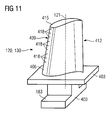
- FIG. 11 shows a perspective view of a blade 120 or guide vane 130 of a turbomachine, which extends along a longitudinal axis 121.
- the turbomachine may be a gas turbine of an aircraft or a power plant for power generation, a steam turbine or a compressor.
- the blade 120, 130 has along the longitudinal axis 121 consecutively a fastening region 400, a blade platform 403 adjacent thereto and an airfoil 406 and a blade tip 415.
- the blade 130 may have at its blade tip 415 another platform (not shown).
- a blade root 183 is formed, which serves for attachment of the blades 120, 130 to a shaft or a disc (not shown).
- the blade root 183 is designed, for example, as a hammer head. Other designs as Christmas tree or Schwalbenschwanzfuß are possible.
- the blade 120, 130 has a leading edge 409 and a trailing edge 412 for a medium flowing past the airfoil 406.
- blades 120, 130 for example, solid metallic materials, in particular superalloys, are used in all regions 400, 403, 406 of the blade 120, 130.
- Such superalloys are for example from EP 1 204 776 B1 .
- EP 1 306 454 .
- the blade 120, 130 can be made by a casting process, also by directional solidification, by a forging process, by a milling process or combinations thereof.
- the blades 120, 130 may have coatings against corrosion or oxidation, e.g. M is at least one element of the group iron (Fe), cobalt (Co), nickel (Ni), X is an active element and stands for yttrium (Y) and / or silicon and / or at least one element of the rare ones Earth, or hafnium (Hf)).
- M is at least one element of the group iron (Fe), cobalt (Co), nickel (Ni)
- X is an active element and stands for yttrium (Y) and / or silicon and / or at least one element of the rare ones Earth, or hafnium (Hf)).
- Such alloys are known from the EP 0 486 489 B1 .
- EP 0 412 397 B1 or EP 1 306 454 A1 The density is preferably 95% of the theoretical density.
- the layer composition comprises Co-30Ni-28Cr-8A1-0, 6Y-0, 7Si or Co-28Ni-24Cr-10Al-0.6Y.
- nickel-based protective layers such as Ni-10Cr-12Al-0.6Y-3Re or Ni-12Co-21Cr-11Al-0.4Y-2Re or Ni-25Co-17Cr-10Al-0.4Y-1 are also preferably used , 5RE.
- thermal barrier coating which is preferably the outermost layer, and consists for example of ZrO 2 , Y 2 O 3 -ZrO 2 , that is, it is not, partially or completely stabilized by yttrium oxide and / or calcium oxide and / or magnesium oxide.
- the thermal barrier coating covers the entire MCrAlX layer.
- suitable coating processes such as electron beam evaporation (EB-PVD)
- stalk-shaped grains are produced in the thermal barrier coating.
- Other coating methods are conceivable, for example atmospheric plasma spraying (APS), LPPS, VPS or CVD.
- the thermal barrier coating may have porous, micro- or macro-cracked grains for better thermal shock resistance.
- the thermal barrier coating is therefore preferably more porous than the MCrAlX layer.
- Refurbishment means that components 120, 130 may need to be deprotected after use (e.g., by sandblasting). This is followed by removal of the corrosion and / or oxidation layers or products. Optionally, even cracks in the component 120, 130 are repaired. This is followed by a re-coating of the component 120, 130 and a renewed use of the component 120, 130.
- the blade 120, 130 may be hollow or solid. If the blade 120, 130 is to be cooled, it is hollow and may still film cooling holes 418 (indicated by dashed lines) on.
Landscapes
- Physics & Mathematics (AREA)
- Optics & Photonics (AREA)
- Engineering & Computer Science (AREA)
- Plasma & Fusion (AREA)
- Mechanical Engineering (AREA)
- Laser Beam Processing (AREA)
- Turbine Rotor Nozzle Sealing (AREA)
- Piezo-Electric Or Mechanical Vibrators, Or Delay Or Filter Circuits (AREA)
Applications Claiming Priority (1)
| Application Number | Priority Date | Filing Date | Title |
|---|---|---|---|
| EP09010546A EP2286955B1 (fr) | 2009-08-17 | 2009-08-17 | Procédé de création d'un trou en utilisant divers réglages laser |
Related Parent Applications (2)
| Application Number | Title | Priority Date | Filing Date |
|---|---|---|---|
| EP09010546.1 Division | 2009-08-17 | ||
| EP09010546A Division EP2286955B1 (fr) | 2009-08-17 | 2009-08-17 | Procédé de création d'un trou en utilisant divers réglages laser |
Publications (3)
| Publication Number | Publication Date |
|---|---|
| EP2292372A2 true EP2292372A2 (fr) | 2011-03-09 |
| EP2292372A3 EP2292372A3 (fr) | 2011-09-07 |
| EP2292372B1 EP2292372B1 (fr) | 2012-10-03 |
Family
ID=41509043
Family Applications (2)
| Application Number | Title | Priority Date | Filing Date |
|---|---|---|---|
| EP10002655A Not-in-force EP2292372B1 (fr) | 2009-08-17 | 2009-08-17 | Procédé de création d'un trou en utilisant divers réglages laser |
| EP09010546A Not-in-force EP2286955B1 (fr) | 2009-08-17 | 2009-08-17 | Procédé de création d'un trou en utilisant divers réglages laser |
Family Applications After (1)
| Application Number | Title | Priority Date | Filing Date |
|---|---|---|---|
| EP09010546A Not-in-force EP2286955B1 (fr) | 2009-08-17 | 2009-08-17 | Procédé de création d'un trou en utilisant divers réglages laser |
Country Status (4)
| Country | Link |
|---|---|
| US (1) | US9040871B2 (fr) |
| EP (2) | EP2292372B1 (fr) |
| CN (1) | CN101992352B (fr) |
| RU (1) | RU2542871C2 (fr) |
Families Citing this family (15)
| Publication number | Priority date | Publication date | Assignee | Title |
|---|---|---|---|---|
| ATE527081T1 (de) * | 2008-03-28 | 2011-10-15 | Siemens Ag | Verfahren zur fertigung einer bohrung |
| US20120205355A1 (en) * | 2009-08-17 | 2012-08-16 | Muenzer Jan | Method for producing an asymmetric diffuser using different laser positions |
| US10113435B2 (en) | 2011-07-15 | 2018-10-30 | United Technologies Corporation | Coated gas turbine components |
| US8631557B2 (en) | 2011-07-19 | 2014-01-21 | Pratt & Whitney Canada Corp. | Laser drilling methods of shallow-angled holes |
| US8624151B2 (en) | 2011-07-19 | 2014-01-07 | Pratt & Whitney Canada Corp. | Laser drilling methods of shallow-angled holes |
| US9434025B2 (en) | 2011-07-19 | 2016-09-06 | Pratt & Whitney Canada Corp. | Laser drilling methods of shallow-angled holes |
| CN103990910B (zh) * | 2014-05-20 | 2015-08-05 | 西安交通大学 | 一种带热障涂层涡轮叶片气膜冷却孔的制备方法 |
| DE102014220525A1 (de) * | 2014-10-09 | 2016-04-14 | Siemens Aktiengesellschaft | Abtragstrategie beim Lasern |
| US11117222B2 (en) | 2014-11-10 | 2021-09-14 | Siemens Energy Global GmbH & Co. KG | Method and device for processing cooling hole on workpiece with laser |
| US10399171B2 (en) | 2015-01-29 | 2019-09-03 | Messer Cutting Systems Inc. | Systems and methods for cutting a plow bolt hole with a cutting torch |
| US9962792B2 (en) * | 2015-02-20 | 2018-05-08 | General Electric Company | Component repair using confined laser drilling |
| EP3179040B1 (fr) | 2015-11-20 | 2021-07-14 | Raytheon Technologies Corporation | Composant pour un moteur à turbine à gaz et procédé associé de fabrication d'un article refroidi par pellicule |
| CN105269158B (zh) * | 2015-11-20 | 2017-04-19 | 西安交通大学 | 一种带热障涂层涡轮叶片冷却孔的高能激光分步加工方法 |
| DE102016222401A1 (de) * | 2016-11-15 | 2018-05-17 | Siemens Aktiengesellschaft | Erzeugung eines Formlochs in einer Wand |
| US11542831B1 (en) * | 2021-08-13 | 2023-01-03 | Raytheon Technologies Corporation | Energy beam positioning during formation of a cooling aperture |
Citations (2)
| Publication number | Priority date | Publication date | Assignee | Title |
|---|---|---|---|---|
| EP0950463A1 (fr) | 1998-03-23 | 1999-10-20 | Abb Research Ltd. | Perforatiom non-circulaire de refroidissement et procédé pour sa fabrication |
| US6420677B1 (en) | 2000-12-20 | 2002-07-16 | Chromalloy Gas Turbine Corporation | Laser machining cooling holes in gas turbine components |
Family Cites Families (22)
| Publication number | Priority date | Publication date | Assignee | Title |
|---|---|---|---|---|
| EP0407969B1 (fr) | 1989-07-14 | 1993-10-06 | MAHO Aktiengesellschaft | Procédé et dispositif pour réaliser des espaces creux dans les pièces à usiner au moyen d'un faisceau laser |
| DE3926479A1 (de) | 1989-08-10 | 1991-02-14 | Siemens Ag | Rheniumhaltige schutzbeschichtung, mit grosser korrosions- und/oder oxidationsbestaendigkeit |
| DE58908611D1 (de) | 1989-08-10 | 1994-12-08 | Siemens Ag | Hochtemperaturfeste korrosionsschutzbeschichtung, insbesondere für gasturbinenbauteile. |
| US6744010B1 (en) * | 1991-08-22 | 2004-06-01 | United Technologies Corporation | Laser drilled holes for film cooling |
| RU2147624C1 (ru) | 1994-10-14 | 2000-04-20 | Сименс АГ | Защитный слой для защиты детали от коррозии, окисления и термической перегрузки, а также способ его изготовления |
| US5747769A (en) * | 1995-11-13 | 1998-05-05 | General Electric Company | Method of laser forming a slot |
| EP0892090B1 (fr) | 1997-02-24 | 2008-04-23 | Sulzer Innotec Ag | Procédé de fabrication de structure monocristallines |
| EP0861927A1 (fr) | 1997-02-24 | 1998-09-02 | Sulzer Innotec Ag | Procédé de fabrication de structures monocristallines |
| EP1306454B1 (fr) | 2001-10-24 | 2004-10-06 | Siemens Aktiengesellschaft | Revêtement protecteur contenant du rhénium pour la protection d'un élément contre l'oxydation et la corrosion aux températures élevées |
| WO1999067435A1 (fr) | 1998-06-23 | 1999-12-29 | Siemens Aktiengesellschaft | Alliage a solidification directionnelle a resistance transversale a la rupture amelioree |
| US6231692B1 (en) | 1999-01-28 | 2001-05-15 | Howmet Research Corporation | Nickel base superalloy with improved machinability and method of making thereof |
| JP2003529677A (ja) | 1999-07-29 | 2003-10-07 | シーメンス アクチエンゲゼルシヤフト | 耐熱性の構造部材及びその製造方法 |
| DE19960797C1 (de) * | 1999-12-16 | 2001-09-13 | Mtu Aero Engines Gmbh | Verfahren zum Herstellen einer Öffnung in einem metallischen Bauteil |
| US6368060B1 (en) * | 2000-05-23 | 2002-04-09 | General Electric Company | Shaped cooling hole for an airfoil |
| GB2381489B (en) * | 2001-10-30 | 2004-11-17 | Rolls Royce Plc | Method of forming a shaped hole |
| DE50112339D1 (de) | 2001-12-13 | 2007-05-24 | Siemens Ag | Hochtemperaturbeständiges Bauteil aus einkristalliner oder polykristalliner Nickel-Basis-Superlegierung |
| WO2005044508A1 (fr) * | 2003-10-06 | 2005-05-19 | Siemens Aktiengesellschaft | Procede pour produire un trou et dispositif |
| EP1674193A1 (fr) | 2004-12-27 | 2006-06-28 | Siemens Aktiengesellschaft | Procédé de fabrication d'un trou |
| EP1681128A1 (fr) | 2005-01-14 | 2006-07-19 | Siemens Aktiengesellschaft | Méthode et dispositif pour fabriquer un trou |
| FR2909297B1 (fr) | 2006-11-30 | 2010-03-05 | Snecma | Procede de percage laser d'une piece en materiau composite a matrice ceramique, trou obtenu par ce procede, piece en materiau composite a matrice ceramique le comportant, turboreacteur comportant une telle piece. |
| US20090057282A1 (en) * | 2007-08-15 | 2009-03-05 | Chunfu Huang | Laser machining method utilizing variable inclination angle |
| ATE527081T1 (de) * | 2008-03-28 | 2011-10-15 | Siemens Ag | Verfahren zur fertigung einer bohrung |
-
2009
- 2009-08-17 EP EP10002655A patent/EP2292372B1/fr not_active Not-in-force
- 2009-08-17 EP EP09010546A patent/EP2286955B1/fr not_active Not-in-force
-
2010
- 2010-08-12 US US12/855,090 patent/US9040871B2/en not_active Expired - Fee Related
- 2010-08-16 RU RU2010134237/02A patent/RU2542871C2/ru not_active IP Right Cessation
- 2010-08-17 CN CN201010256792.0A patent/CN101992352B/zh not_active Expired - Fee Related
Patent Citations (3)
| Publication number | Priority date | Publication date | Assignee | Title |
|---|---|---|---|---|
| EP0950463A1 (fr) | 1998-03-23 | 1999-10-20 | Abb Research Ltd. | Perforatiom non-circulaire de refroidissement et procédé pour sa fabrication |
| EP0950463B1 (fr) | 1998-03-23 | 2002-01-23 | Alstom | Perforation non-circulaire de refroidissement et procédé pour sa fabrication |
| US6420677B1 (en) | 2000-12-20 | 2002-07-16 | Chromalloy Gas Turbine Corporation | Laser machining cooling holes in gas turbine components |
Also Published As
| Publication number | Publication date |
|---|---|
| EP2286955B1 (fr) | 2012-06-13 |
| US20110036819A1 (en) | 2011-02-17 |
| EP2292372B1 (fr) | 2012-10-03 |
| EP2292372A3 (fr) | 2011-09-07 |
| CN101992352B (zh) | 2015-04-01 |
| CN101992352A (zh) | 2011-03-30 |
| EP2286955A1 (fr) | 2011-02-23 |
| RU2010134237A (ru) | 2012-02-27 |
| US9040871B2 (en) | 2015-05-26 |
| RU2542871C2 (ru) | 2015-02-27 |
Similar Documents
| Publication | Publication Date | Title |
|---|---|---|
| EP2286955B1 (fr) | Procédé de création d'un trou en utilisant divers réglages laser | |
| EP2467228B1 (fr) | Procédé de création d'un trou en utilisant divers réglages laser | |
| EP1973688B1 (fr) | Procede de realisation d'un trou | |
| EP1670612B1 (fr) | Procede pour produire un trou | |
| WO2010112553A2 (fr) | Procédé de soudage et pièce associée | |
| EP2384845A1 (fr) | Perçage au laser sans formation de bavure | |
| EP3500395B1 (fr) | Procédé en 3 étapes de fabrication d'orifices de refroidissement par air utlisant un laser dans le domaine des nanosecondes et des millisecondes et pièce obtenue | |
| EP2369131A1 (fr) | Réparation de bords d'un composant à l'aide de bandes PSP et composant | |
| EP2186594A1 (fr) | Procédé et dispositif de préchauffage lors du soudage utilisant un deuxième faisceau laser | |
| DE102008016170A1 (de) | Bauteil mit sich überlappenden Schweißnähten und ein Verfahren zur Herstellung | |
| WO2009065753A1 (fr) | Procédé de brasage de fissures larges | |
| DE102008019636A1 (de) | Bauteil mit Schweißnaht und Verfahren zur Herstellung einer Schweißnaht | |
| EP2241397A1 (fr) | Soudage de trous, procédé de revêtement de tiges de soudage | |
| EP2604378B1 (fr) | Réouverture d'ouvertures pour air de refroidissement à l'aide d'un laser à nanosecondes dans le domaine des microsecondes | |
| EP2487006A1 (fr) | Traitement au laser multiple sous des angles différents | |
| EP2138258A1 (fr) | Procédé de soudage à profil de température à plusieurs niveaux | |
| EP2733236A1 (fr) | Système de couche céramique double couche avec couche extérieure poreuse et évidements à l'intérieur | |
| WO2018114766A1 (fr) | Procédé d'assemblage de segments de composants à gaz chaud par brasage et composant à gaz chaud correspondant | |
| EP2498941B1 (fr) | Coupe par étincelage dotée d'une électrode en fil d'acier à déroulement épais | |
| EP2345499A1 (fr) | Traitement par étincelage après revêtement avec des électrodes auxiliaires dans un composant pendant le revêtement | |
| EP2452775A1 (fr) | Procédé de forage raccourci d'un trou | |
| EP2322683A1 (fr) | Procédé de revêtement d'un composant doté d'un orifice partiellement fermé et procédé d'ouverture de l'orifice | |
| WO2009089840A1 (fr) | Procédé et dispositif d'usinage par électro-érosion régulé | |
| EP1946873A1 (fr) | Electrode dýérodeuse modulaire et son utilisation | |
| EP3047935A1 (fr) | Procede de fabrication d'un trou |
Legal Events
| Date | Code | Title | Description |
|---|---|---|---|
| PUAI | Public reference made under article 153(3) epc to a published international application that has entered the european phase |
Free format text: ORIGINAL CODE: 0009012 |
|
| AC | Divisional application: reference to earlier application |
Ref document number: 2286955 Country of ref document: EP Kind code of ref document: P |
|
| AK | Designated contracting states |
Kind code of ref document: A2 Designated state(s): AT BE BG CH CY CZ DE DK EE ES FI FR GB GR HR HU IE IS IT LI LT LU LV MC MK MT NL NO PL PT RO SE SI SK SM TR |
|
| AX | Request for extension of the european patent |
Extension state: AL BA RS |
|
| 17P | Request for examination filed |
Effective date: 20110321 |
|
| PUAL | Search report despatched |
Free format text: ORIGINAL CODE: 0009013 |
|
| AK | Designated contracting states |
Kind code of ref document: A3 Designated state(s): AT BE BG CH CY CZ DE DK EE ES FI FR GB GR HR HU IE IS IT LI LT LU LV MC MK MT NL NO PL PT RO SE SI SK SM TR |
|
| AX | Request for extension of the european patent |
Extension state: AL BA RS |
|
| RIC1 | Information provided on ipc code assigned before grant |
Ipc: B23K 26/38 20060101AFI20110729BHEP |
|
| 17Q | First examination report despatched |
Effective date: 20111220 |
|
| GRAP | Despatch of communication of intention to grant a patent |
Free format text: ORIGINAL CODE: EPIDOSNIGR1 |
|
| GRAS | Grant fee paid |
Free format text: ORIGINAL CODE: EPIDOSNIGR3 |
|
| GRAA | (expected) grant |
Free format text: ORIGINAL CODE: 0009210 |
|
| AC | Divisional application: reference to earlier application |
Ref document number: 2286955 Country of ref document: EP Kind code of ref document: P |
|
| AK | Designated contracting states |
Kind code of ref document: B1 Designated state(s): AT BE BG CH CY CZ DE DK EE ES FI FR GB GR HR HU IE IS IT LI LT LU LV MC MK MT NL NO PL PT RO SE SI SK SM TR |
|
| REG | Reference to a national code |
Ref country code: GB Ref legal event code: FG4D Free format text: NOT ENGLISH |
|
| REG | Reference to a national code |
Ref country code: AT Ref legal event code: REF Ref document number: 577744 Country of ref document: AT Kind code of ref document: T Effective date: 20121015 Ref country code: CH Ref legal event code: EP |
|
| REG | Reference to a national code |
Ref country code: IE Ref legal event code: FG4D Free format text: LANGUAGE OF EP DOCUMENT: GERMAN |
|
| REG | Reference to a national code |
Ref country code: CH Ref legal event code: NV Representative=s name: SIEMENS SCHWEIZ AG, CH |
|
| REG | Reference to a national code |
Ref country code: DE Ref legal event code: R096 Ref document number: 502009005001 Country of ref document: DE Effective date: 20121129 |
|
| REG | Reference to a national code |
Ref country code: NL Ref legal event code: T3 |
|
| PG25 | Lapsed in a contracting state [announced via postgrant information from national office to epo] |
Ref country code: SI Free format text: LAPSE BECAUSE OF FAILURE TO SUBMIT A TRANSLATION OF THE DESCRIPTION OR TO PAY THE FEE WITHIN THE PRESCRIBED TIME-LIMIT Effective date: 20121003 |
|
| RAP2 | Party data changed (patent owner data changed or rights of a patent transferred) |
Owner name: SIEMENS AKTIENGESELLSCHAFT |
|
| REG | Reference to a national code |
Ref country code: LT Ref legal event code: MG4D |
|
| PG25 | Lapsed in a contracting state [announced via postgrant information from national office to epo] |
Ref country code: SE Free format text: LAPSE BECAUSE OF FAILURE TO SUBMIT A TRANSLATION OF THE DESCRIPTION OR TO PAY THE FEE WITHIN THE PRESCRIBED TIME-LIMIT Effective date: 20121003 Ref country code: FI Free format text: LAPSE BECAUSE OF FAILURE TO SUBMIT A TRANSLATION OF THE DESCRIPTION OR TO PAY THE FEE WITHIN THE PRESCRIBED TIME-LIMIT Effective date: 20121003 Ref country code: NO Free format text: LAPSE BECAUSE OF FAILURE TO SUBMIT A TRANSLATION OF THE DESCRIPTION OR TO PAY THE FEE WITHIN THE PRESCRIBED TIME-LIMIT Effective date: 20130103 Ref country code: ES Free format text: LAPSE BECAUSE OF FAILURE TO SUBMIT A TRANSLATION OF THE DESCRIPTION OR TO PAY THE FEE WITHIN THE PRESCRIBED TIME-LIMIT Effective date: 20130114 Ref country code: HR Free format text: LAPSE BECAUSE OF FAILURE TO SUBMIT A TRANSLATION OF THE DESCRIPTION OR TO PAY THE FEE WITHIN THE PRESCRIBED TIME-LIMIT Effective date: 20121003 Ref country code: IS Free format text: LAPSE BECAUSE OF FAILURE TO SUBMIT A TRANSLATION OF THE DESCRIPTION OR TO PAY THE FEE WITHIN THE PRESCRIBED TIME-LIMIT Effective date: 20130203 Ref country code: LT Free format text: LAPSE BECAUSE OF FAILURE TO SUBMIT A TRANSLATION OF THE DESCRIPTION OR TO PAY THE FEE WITHIN THE PRESCRIBED TIME-LIMIT Effective date: 20121003 |
|
| PG25 | Lapsed in a contracting state [announced via postgrant information from national office to epo] |
Ref country code: GR Free format text: LAPSE BECAUSE OF FAILURE TO SUBMIT A TRANSLATION OF THE DESCRIPTION OR TO PAY THE FEE WITHIN THE PRESCRIBED TIME-LIMIT Effective date: 20130104 Ref country code: PL Free format text: LAPSE BECAUSE OF FAILURE TO SUBMIT A TRANSLATION OF THE DESCRIPTION OR TO PAY THE FEE WITHIN THE PRESCRIBED TIME-LIMIT Effective date: 20121003 Ref country code: LV Free format text: LAPSE BECAUSE OF FAILURE TO SUBMIT A TRANSLATION OF THE DESCRIPTION OR TO PAY THE FEE WITHIN THE PRESCRIBED TIME-LIMIT Effective date: 20121003 Ref country code: PT Free format text: LAPSE BECAUSE OF FAILURE TO SUBMIT A TRANSLATION OF THE DESCRIPTION OR TO PAY THE FEE WITHIN THE PRESCRIBED TIME-LIMIT Effective date: 20130204 |
|
| PG25 | Lapsed in a contracting state [announced via postgrant information from national office to epo] |
Ref country code: DK Free format text: LAPSE BECAUSE OF FAILURE TO SUBMIT A TRANSLATION OF THE DESCRIPTION OR TO PAY THE FEE WITHIN THE PRESCRIBED TIME-LIMIT Effective date: 20121003 Ref country code: EE Free format text: LAPSE BECAUSE OF FAILURE TO SUBMIT A TRANSLATION OF THE DESCRIPTION OR TO PAY THE FEE WITHIN THE PRESCRIBED TIME-LIMIT Effective date: 20121003 Ref country code: SK Free format text: LAPSE BECAUSE OF FAILURE TO SUBMIT A TRANSLATION OF THE DESCRIPTION OR TO PAY THE FEE WITHIN THE PRESCRIBED TIME-LIMIT Effective date: 20121003 Ref country code: BG Free format text: LAPSE BECAUSE OF FAILURE TO SUBMIT A TRANSLATION OF THE DESCRIPTION OR TO PAY THE FEE WITHIN THE PRESCRIBED TIME-LIMIT Effective date: 20130103 Ref country code: CZ Free format text: LAPSE BECAUSE OF FAILURE TO SUBMIT A TRANSLATION OF THE DESCRIPTION OR TO PAY THE FEE WITHIN THE PRESCRIBED TIME-LIMIT Effective date: 20121003 |
|
| PLBE | No opposition filed within time limit |
Free format text: ORIGINAL CODE: 0009261 |
|
| STAA | Information on the status of an ep patent application or granted ep patent |
Free format text: STATUS: NO OPPOSITION FILED WITHIN TIME LIMIT |
|
| PG25 | Lapsed in a contracting state [announced via postgrant information from national office to epo] |
Ref country code: RO Free format text: LAPSE BECAUSE OF FAILURE TO SUBMIT A TRANSLATION OF THE DESCRIPTION OR TO PAY THE FEE WITHIN THE PRESCRIBED TIME-LIMIT Effective date: 20121003 |
|
| 26N | No opposition filed |
Effective date: 20130704 |
|
| REG | Reference to a national code |
Ref country code: DE Ref legal event code: R097 Ref document number: 502009005001 Country of ref document: DE Effective date: 20130704 |
|
| PG25 | Lapsed in a contracting state [announced via postgrant information from national office to epo] |
Ref country code: CY Free format text: LAPSE BECAUSE OF FAILURE TO SUBMIT A TRANSLATION OF THE DESCRIPTION OR TO PAY THE FEE WITHIN THE PRESCRIBED TIME-LIMIT Effective date: 20121003 |
|
| BERE | Be: lapsed |
Owner name: SIEMENS A.G. Effective date: 20130831 |
|
| PG25 | Lapsed in a contracting state [announced via postgrant information from national office to epo] |
Ref country code: MC Free format text: LAPSE BECAUSE OF FAILURE TO SUBMIT A TRANSLATION OF THE DESCRIPTION OR TO PAY THE FEE WITHIN THE PRESCRIBED TIME-LIMIT Effective date: 20121003 |
|
| REG | Reference to a national code |
Ref country code: IE Ref legal event code: MM4A |
|
| PG25 | Lapsed in a contracting state [announced via postgrant information from national office to epo] |
Ref country code: BE Free format text: LAPSE BECAUSE OF NON-PAYMENT OF DUE FEES Effective date: 20130831 |
|
| PG25 | Lapsed in a contracting state [announced via postgrant information from national office to epo] |
Ref country code: IE Free format text: LAPSE BECAUSE OF NON-PAYMENT OF DUE FEES Effective date: 20130817 |
|
| PG25 | Lapsed in a contracting state [announced via postgrant information from national office to epo] |
Ref country code: SM Free format text: LAPSE BECAUSE OF FAILURE TO SUBMIT A TRANSLATION OF THE DESCRIPTION OR TO PAY THE FEE WITHIN THE PRESCRIBED TIME-LIMIT Effective date: 20121003 |
|
| PG25 | Lapsed in a contracting state [announced via postgrant information from national office to epo] |
Ref country code: TR Free format text: LAPSE BECAUSE OF FAILURE TO SUBMIT A TRANSLATION OF THE DESCRIPTION OR TO PAY THE FEE WITHIN THE PRESCRIBED TIME-LIMIT Effective date: 20121003 Ref country code: MT Free format text: LAPSE BECAUSE OF FAILURE TO SUBMIT A TRANSLATION OF THE DESCRIPTION OR TO PAY THE FEE WITHIN THE PRESCRIBED TIME-LIMIT Effective date: 20121003 |
|
| PG25 | Lapsed in a contracting state [announced via postgrant information from national office to epo] |
Ref country code: MK Free format text: LAPSE BECAUSE OF FAILURE TO SUBMIT A TRANSLATION OF THE DESCRIPTION OR TO PAY THE FEE WITHIN THE PRESCRIBED TIME-LIMIT Effective date: 20121003 Ref country code: HU Free format text: LAPSE BECAUSE OF FAILURE TO SUBMIT A TRANSLATION OF THE DESCRIPTION OR TO PAY THE FEE WITHIN THE PRESCRIBED TIME-LIMIT; INVALID AB INITIO Effective date: 20090817 Ref country code: LU Free format text: LAPSE BECAUSE OF NON-PAYMENT OF DUE FEES Effective date: 20130817 |
|
| REG | Reference to a national code |
Ref country code: AT Ref legal event code: MM01 Ref document number: 577744 Country of ref document: AT Kind code of ref document: T Effective date: 20140817 |
|
| PG25 | Lapsed in a contracting state [announced via postgrant information from national office to epo] |
Ref country code: AT Free format text: LAPSE BECAUSE OF NON-PAYMENT OF DUE FEES Effective date: 20140817 |
|
| REG | Reference to a national code |
Ref country code: FR Ref legal event code: PLFP Year of fee payment: 8 |
|
| REG | Reference to a national code |
Ref country code: FR Ref legal event code: PLFP Year of fee payment: 9 |
|
| REG | Reference to a national code |
Ref country code: CH Ref legal event code: PCOW Free format text: NEW ADDRESS: WERNER-VON-SIEMENS-STRASSE 1, 80333 MUENCHEN (DE) |
|
| REG | Reference to a national code |
Ref country code: FR Ref legal event code: PLFP Year of fee payment: 10 |
|
| PGFP | Annual fee paid to national office [announced via postgrant information from national office to epo] |
Ref country code: FR Payment date: 20180822 Year of fee payment: 10 Ref country code: NL Payment date: 20180809 Year of fee payment: 10 Ref country code: IT Payment date: 20180829 Year of fee payment: 10 |
|
| PGFP | Annual fee paid to national office [announced via postgrant information from national office to epo] |
Ref country code: GB Payment date: 20180809 Year of fee payment: 10 |
|
| PGFP | Annual fee paid to national office [announced via postgrant information from national office to epo] |
Ref country code: DE Payment date: 20181019 Year of fee payment: 10 |
|
| PGFP | Annual fee paid to national office [announced via postgrant information from national office to epo] |
Ref country code: CH Payment date: 20181107 Year of fee payment: 10 |
|
| REG | Reference to a national code |
Ref country code: DE Ref legal event code: R119 Ref document number: 502009005001 Country of ref document: DE |
|
| REG | Reference to a national code |
Ref country code: NL Ref legal event code: MM Effective date: 20190901 |
|
| GBPC | Gb: european patent ceased through non-payment of renewal fee |
Effective date: 20190817 |
|
| PG25 | Lapsed in a contracting state [announced via postgrant information from national office to epo] |
Ref country code: LI Free format text: LAPSE BECAUSE OF NON-PAYMENT OF DUE FEES Effective date: 20190831 Ref country code: CH Free format text: LAPSE BECAUSE OF NON-PAYMENT OF DUE FEES Effective date: 20190831 |
|
| PG25 | Lapsed in a contracting state [announced via postgrant information from national office to epo] |
Ref country code: DE Free format text: LAPSE BECAUSE OF NON-PAYMENT OF DUE FEES Effective date: 20200303 Ref country code: FR Free format text: LAPSE BECAUSE OF NON-PAYMENT OF DUE FEES Effective date: 20190831 Ref country code: NL Free format text: LAPSE BECAUSE OF NON-PAYMENT OF DUE FEES Effective date: 20190901 |
|
| PG25 | Lapsed in a contracting state [announced via postgrant information from national office to epo] |
Ref country code: GB Free format text: LAPSE BECAUSE OF NON-PAYMENT OF DUE FEES Effective date: 20190817 Ref country code: IT Free format text: LAPSE BECAUSE OF NON-PAYMENT OF DUE FEES Effective date: 20190817 |