EP2292385A2 - Machine-outil manuelle dotée d'une poignée latérale équipée d'un dispositif d'introduction intégré - Google Patents
Machine-outil manuelle dotée d'une poignée latérale équipée d'un dispositif d'introduction intégré Download PDFInfo
- Publication number
- EP2292385A2 EP2292385A2 EP10173193A EP10173193A EP2292385A2 EP 2292385 A2 EP2292385 A2 EP 2292385A2 EP 10173193 A EP10173193 A EP 10173193A EP 10173193 A EP10173193 A EP 10173193A EP 2292385 A2 EP2292385 A2 EP 2292385A2
- Authority
- EP
- European Patent Office
- Prior art keywords
- side handle
- hand tool
- tool according
- disc
- suction head
- Prior art date
- Legal status (The legal status is an assumption and is not a legal conclusion. Google has not performed a legal analysis and makes no representation as to the accuracy of the status listed.)
- Withdrawn
Links
- 239000007788 liquid Substances 0.000 claims abstract description 31
- 238000011010 flushing procedure Methods 0.000 claims description 17
- 230000001105 regulatory effect Effects 0.000 claims description 8
- 230000013011 mating Effects 0.000 claims description 5
- 229910000831 Steel Inorganic materials 0.000 claims description 3
- 239000010959 steel Substances 0.000 claims description 3
- 230000002262 irrigation Effects 0.000 abstract 1
- 238000003973 irrigation Methods 0.000 abstract 1
- 238000001816 cooling Methods 0.000 description 16
- 238000005553 drilling Methods 0.000 description 13
- 239000000463 material Substances 0.000 description 5
- 238000007789 sealing Methods 0.000 description 3
- 230000005540 biological transmission Effects 0.000 description 2
- 229910003460 diamond Inorganic materials 0.000 description 2
- 239000010432 diamond Substances 0.000 description 2
- 235000010678 Paulownia tomentosa Nutrition 0.000 description 1
- 240000002834 Paulownia tomentosa Species 0.000 description 1
- XAGFODPZIPBFFR-UHFFFAOYSA-N aluminium Chemical compound [Al] XAGFODPZIPBFFR-UHFFFAOYSA-N 0.000 description 1
- 229910052782 aluminium Inorganic materials 0.000 description 1
- 230000007423 decrease Effects 0.000 description 1
- 230000000694 effects Effects 0.000 description 1
- 230000002349 favourable effect Effects 0.000 description 1
- 230000010354 integration Effects 0.000 description 1
- XLYOFNOQVPJJNP-UHFFFAOYSA-N water Substances O XLYOFNOQVPJJNP-UHFFFAOYSA-N 0.000 description 1
Images

Classifications
-
- B—PERFORMING OPERATIONS; TRANSPORTING
- B28—WORKING CEMENT, CLAY, OR STONE
- B28D—WORKING STONE OR STONE-LIKE MATERIALS
- B28D7/00—Accessories specially adapted for use with machines or devices of the preceding groups
- B28D7/02—Accessories specially adapted for use with machines or devices of the preceding groups for removing or laying dust, e.g. by spraying liquids; for cooling work
-
- B—PERFORMING OPERATIONS; TRANSPORTING
- B25—HAND TOOLS; PORTABLE POWER-DRIVEN TOOLS; MANIPULATORS
- B25F—COMBINATION OR MULTI-PURPOSE TOOLS NOT OTHERWISE PROVIDED FOR; DETAILS OR COMPONENTS OF PORTABLE POWER-DRIVEN TOOLS NOT PARTICULARLY RELATED TO THE OPERATIONS PERFORMED AND NOT OTHERWISE PROVIDED FOR
- B25F5/00—Details or components of portable power-driven tools not particularly related to the operations performed and not otherwise provided for
- B25F5/02—Construction of casings, bodies or handles
- B25F5/025—Construction of casings, bodies or handles with torque reaction bars for rotary tools
- B25F5/026—Construction of casings, bodies or handles with torque reaction bars for rotary tools in the form of an auxiliary handle
Definitions
- the present invention relates to a hand tool according to the preamble of patent claim 1.
- a known hand tool machine which is designed as a drilling device, has a side handle with an integrated in the side handle feeder for a cooling and / or rinsing liquid, which flows via a flushing suction head to the processing point on.
- the side handle can be attached to a plurality of connection points in the form of threaded holes on the flushing suction head of the drilling device.
- a disadvantage of the known drilling apparatus is that the side handle can not be screwed at an arbitrary angle in the ergonomically most favorable position for the operator.
- the object of the present invention is in contrast to further develop a side handle with integrated feeder for a cooling and / or rinsing liquid to the effect that the side handle can be arranged at any angle.
- the side handle is formed pivotable about an axis of rotation, the operator can attach the side handle in a desired position and adapted to the respective processing task.
- the side handle is preferably pivotable through 360 ° about the axis of rotation, so that the side handle can be arranged in any desired position.
- the side handle is detachably attached to the flushing / suction head by means of a threaded device and preferably designed to be rotatable about a rotation axis.
- the side handle on an adjustment, wherein the side handle is adjustable between a locked state and an unlocked state.
- the adjusting device has a latching device with a Contour on, wherein the contour is in the locked state of the side handle with a corresponding mating contour of a housing portion of the housing in engagement. Due to the positive connection between the contour of the latching device and the mating contour of the housing portion of the side handle is securely attached.
- the latching device is formed in two parts with a latching element and a disc, wherein the disc is arranged coaxially to the axle element between the latching element and a stop shoulder of the axle. In the locked state of the side handle, the disc abuts against the stop shoulder of the axle.
- the two-part design of the locking device has the advantage that locking element and disc can be made of different materials.
- the locking element consists of a material that is as light as possible and has good sliding properties.
- the disc is made of a material that can absorb the forces occurring during power transmission without deformation.
- the locking element is designed as a plastic part and the disc as a steel disc. This material combination ensures that the latching device is lightweight. A plastic part glides well against an aluminum housing and the disc transfers the forces without deformation.
- a regulating device for adjusting the liquid supply is provided, wherein the regulating device is integrated in the side handle.
- the integration of the regulator in the side handle has the advantage that the operator can adjust the liquid supply without having to loosen the hand from the side handle.
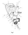
- Fig. 1 shows a hand tool 1 according to the invention , which is designed as a drilling device, in a schematic, perspective view.
- the drilling device 1 comprises a housing 2 consisting of a handle 3 for holding and guiding the drilling device 1, a motor housing section 4 and a gear housing section 5.
- a drive motor 6 is arranged for a tool holder 7 , with which a tool 8, for example a diamond drill bit, about a rotational axis 9 is driven to rotate.
- gear housing section 5 which is arranged between the motor housing section 4 and the tool holder 7, there is a gear 10, which transmits the torque of the drive motor 9 via a rotary spindle 11 to the tool holder 7.
- Engine, gear and rotary spindle are referred to together as a drive device 12 .
- a rinsing / suction head 13 adjoins the gear housing section 5 on the tool side , via which a cooling and / or rinsing liquid is supplied to the drilling device 1.
- a second handle in the form of a side handle 14 is arranged.
- the side handle 14 is arranged in a plane which is substantially parallel to the axis of rotation 9, and formed about the axis of rotation 9 by means of an adjusting device 15 continuously adjustable to 360 °.
- the supply of cooling and / or rinsing liquid via a feed device 16 which is integrated in the side handle 14.
- the cooling and / or rinsing liquid is transported by the feed device 16 via the side handle 14 into the rinsing / suction head 13.
- Fig. 2 shows the flushing / suction head 13 of the Fig. 1 illustrated drilling apparatus 1 with the adjustable side handle 14 and integrated in the side handle 14 feeder 16 for the cooling and / or rinsing liquid in a sectional view along the line AA in a plane perpendicular to the axis of rotation 9.
- the side handle 14 consists of a handle member 20 and a shaft member 21 which are rotatably connected to each other.
- the axle 21 is connected via a threaded device 22 releasably connected to the flushing / suction head 13. If the side handle 14 about an axis of rotation 23 which is parallel to the longitudinal extent of the handle member 20 and the shaft member 21, rotated in the direction of an arrow 24 in the counterclockwise direction, the axle 21 is rotated out of the flushing / suction head 13.
- the cooling and / or rinsing liquid supply means 16 comprises a connection element 25 in the form of a connection for connecting an external liquid source, a regulating device 26 for adjusting the amount of liquid supplied and a transport system 27 for transporting the liquid through the side handle 14 to the rinsing / suction head 13.
- the cooling and / or rinsing liquid passes via a connecting line 28 which is connected to the nozzle 25, from the external liquid source to the feeder 16th
- the regulating device 26 includes a shut-off device 29, for example in the form of a ball valve, and a dial 30 for adjusting the amount of liquid supplied.
- the dial 30 is arranged so that the operator can operate the dial 30 while holding the side handle 14 by means of one or more fingers.
- the transport system 27 consists of a water connection 31 and a control device in the form of a flow indicator 32, which are arranged coaxially to the axle 21 and limit a liquid space 33 .
- the operator of the drilling device 1 monitors the flow of cooling and / or rinsing liquid into the flushing / suction head 13 by means of the control device 32 designed as a flow indicator.
- sealing elements 34, 35, 36 are provided for example, in the form of O-rings are formed.
- the axle element 21 has on the rinse / suction head 13 facing the end of a longitudinal bore 37 , which communicates via a connecting bore 38 with the liquid space 33 of the transport system 27 in connection. So that between the axle 21 and the flushing / suction head 13 no cooling and / or rinsing liquid enters the external environment, at the the rinsing / suction head 13 facing the end of the axle 21 in a circumferential recess of the axle 21, a further sealing element 39th , which is formed for example in the form of an O-ring arranged.
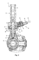
- Fig. 3 shows the flushing / suction head 13 of the Fig. 1 shown drilling apparatus 1 with the side handle 14 and the integrated in the side handle 14 feeder 16 for the Cooling and / or rinsing liquid in a sectional view along the line AA in a plane parallel to the axis of rotation 9.
- the cooling and / or rinsing liquid flows from the external liquid source coming via the connecting line 28 in the regulating device 26.
- the regulating device 26 is connected to the transport system 27, so that the cooling and / or rinsing liquid flows into the liquid space 33 and from there via the connection bore 38 in the longitudinal bore 37 of the axle 21st
- the rotary spindle 11 is formed in the region of the flushing / suction head 13 over part of its length as a hollow spindle with an axially extending longitudinal bore 40 .
- the rotary spindle 11 1 has at least one connecting bore 41 running in the radial direction, which connects the longitudinal bore 40 of the rotary spindle 11 to the flushing suction head 13 via an inflow channel 42 .
- the inflow channel 42 is connected to the longitudinal bore 37 which extends in the axle 21.
- a sealing element 43 seals the rotary spindle 11 against the gear housing section 5.
- the axle element 21 in the longitudinal bore 37 has a check valve 45, for example in the form of a ball valve ,
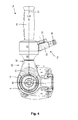
- Fig. 4 shows the connection of the side handle 14 to the gear housing section 5 in a sectional view in a plane perpendicular to the axis of rotation 9 along a line parallel to the line AA, tool-shifted line in a locked state of the side handle 14th
- the side handle 14 comprises a detent element 51, which is arranged coaxially to the axle 21 between the gear housing section 5 and the flow indicator 32.
- the locking element 51 is formed as a plastic part.
- a disc 52 which is arranged coaxially with the axle 21.
- the axle 21 is stepped with a stop shoulder 53 (FIG. Fig. 3 ) educated. When locked side handle 14, the disc 52 abuts against the stop shoulder 53.
- the latching element 51 has, on a side facing the flushing / suction head 13, a contour 54 which corresponds to a countercontour 55 attached to the gearbox housing section 5.
- the contour 54 of the locking element 51 is in engagement with the mating contour 55 of the gear housing section fifth
- the handle member 20 is rotated counterclockwise, i. in the direction of arrow 24, rotated about the axis of rotation 23.
- the shaft element 21 is unscrewed from the flushing / suction head 13 via the threaded device 22.
- a gap is formed between the disc 52 and the stop shoulder 53 of the axle 21, a gap is formed. If the side handle 14 is pivoted about the axis of rotation 9, the locking element 51 moves in the direction of the stop shoulder 53 and the locking element 51 is disengaged from the mating contour 55 of the gear housing section 5.
- the side handle 14 can be pivoted about the axis of rotation 9 in the desired position.
- the handle member 20 is rotated clockwise, i. against the direction of the arrow 24, rotated about the axis of rotation 23.
- the shaft element 21 is screwed into the flushing / suction head 13 via the threaded device 22 and the gap between the disk 52 and the stop shoulder 53 of the axle element 21 decreases until the disk 52 comes into abutment against the stop shoulder 53 ,
- the gear housing section 5 and the latching element 51 are on the contour 54 and counter contour 55 in engagement with each other and the side handle 14 is fixed in position.
- the latching device 50 is formed in two parts from the latching element 51 and the disc 52.
- the locking element 51 is formed as a plastic part.
- the disc 52 is formed as a steel disc and ensures that the locking element 51 does not deform during the power transmission.
- the latching device 50 is to ensure that the locking element 51 and the disc 52 are connected captively.
- the latching device can be made in one piece from a material which is as light as possible on the one hand and on the other hand can absorb the forces occurring without deformation.
- the in the FIGS. 1 to 4 Hand tool 1 shown is designed as a drilling device.
- the pivotable side handle 14 with integrated feeder 16 is suitable for all hand tool machines which have a side handle and perform a cooling and / or rinsing liquid via the hand tool, such as diamond saws.
Landscapes
- Engineering & Computer Science (AREA)
- Mechanical Engineering (AREA)
- Drilling And Boring (AREA)
- Portable Power Tools In General (AREA)
Applications Claiming Priority (1)
| Application Number | Priority Date | Filing Date | Title |
|---|---|---|---|
| DE200910039843 DE102009039843A1 (de) | 2009-09-03 | 2009-09-03 | Handwerkzeugmaschine mit einem Seitenhandgriff mit integrierter Zuführeinrichtung |
Publications (2)
| Publication Number | Publication Date |
|---|---|
| EP2292385A2 true EP2292385A2 (fr) | 2011-03-09 |
| EP2292385A3 EP2292385A3 (fr) | 2011-07-27 |
Family
ID=43302721
Family Applications (1)
| Application Number | Title | Priority Date | Filing Date |
|---|---|---|---|
| EP10173193A Withdrawn EP2292385A3 (fr) | 2009-09-03 | 2010-08-18 | Machine-outil manuelle dotée d'une poignée latérale équipée d'un dispositif d'introduction intégré |
Country Status (2)
| Country | Link |
|---|---|
| EP (1) | EP2292385A3 (fr) |
| DE (1) | DE102009039843A1 (fr) |
Cited By (5)
| Publication number | Priority date | Publication date | Assignee | Title |
|---|---|---|---|---|
| US20130195570A1 (en) * | 2010-04-16 | 2013-08-01 | Husqvarna Ab | Core drilling machine and a handle assembly for a core drilling machine |
| GB2546176A (en) * | 2016-01-11 | 2017-07-12 | C Vasudeva Kailash | Power tool with detachable auxiliary handle |
| EP3670099A1 (fr) | 2018-12-17 | 2020-06-24 | Hilti Aktiengesellschaft | Outil électrique portable et poignée latérale |
| EP4219082A1 (fr) * | 2017-07-31 | 2023-08-02 | Milwaukee Electric Tool Corporation | Outil électrique rotatif |
| US12611761B2 (en) | 2021-11-24 | 2026-04-28 | Milwaukee Electric Tool Corporation | Grinder including enhanced sensing and component detection |
Family Cites Families (7)
| Publication number | Priority date | Publication date | Assignee | Title |
|---|---|---|---|---|
| DE2548100A1 (de) * | 1975-10-28 | 1977-05-12 | Bosch Gmbh Robert | Anbauvorrichtung zum absaugen von bohrklein |
| DE19619023A1 (de) * | 1996-05-10 | 1997-11-13 | Bosch Gmbh Robert | Bohreinrichtung |
| DE19647575A1 (de) * | 1996-05-13 | 1997-11-20 | Geisler Und Kuper Gmbh Diamant | Bohreinrichtung mit Bohrstaubabsaugung oder Wasserspülung |
| US7191494B2 (en) * | 2003-08-11 | 2007-03-20 | Badiali John A | Stabilizer for rotary tools |
| US20080078067A1 (en) * | 2006-09-01 | 2008-04-03 | Nicolantonio Aldo D | Handle |
| DE102007047030A1 (de) * | 2007-10-01 | 2009-04-02 | Metabowerke Gmbh | Elektrohandwerkzeuggerät |
| DE102007047881A1 (de) * | 2007-11-28 | 2009-06-04 | Hilti Aktiengesellschaft | Handwerkzeugmaschine mit Zusatzhandgriff mit Spannband |
-
2009
- 2009-09-03 DE DE200910039843 patent/DE102009039843A1/de not_active Ceased
-
2010
- 2010-08-18 EP EP10173193A patent/EP2292385A3/fr not_active Withdrawn
Non-Patent Citations (1)
| Title |
|---|
| None |
Cited By (9)
| Publication number | Priority date | Publication date | Assignee | Title |
|---|---|---|---|---|
| US20130195570A1 (en) * | 2010-04-16 | 2013-08-01 | Husqvarna Ab | Core drilling machine and a handle assembly for a core drilling machine |
| US9149876B2 (en) * | 2010-04-16 | 2015-10-06 | Husqvarna Ab | Core drilling machine and a handle assembly for a core drilling machine |
| GB2546176A (en) * | 2016-01-11 | 2017-07-12 | C Vasudeva Kailash | Power tool with detachable auxiliary handle |
| GB2546176B (en) * | 2016-01-11 | 2021-02-10 | C Vasudeva Kailash | Power tool with detachable auxiliary handle |
| EP4219082A1 (fr) * | 2017-07-31 | 2023-08-02 | Milwaukee Electric Tool Corporation | Outil électrique rotatif |
| US12121980B2 (en) | 2017-07-31 | 2024-10-22 | Milwaukee Electric Tool Corporation | Rotary power tool |
| EP3670099A1 (fr) | 2018-12-17 | 2020-06-24 | Hilti Aktiengesellschaft | Outil électrique portable et poignée latérale |
| WO2020126348A1 (fr) | 2018-12-17 | 2020-06-25 | Hilti Aktiengesellschaft | Outil électrique portatif et poignée latérale |
| US12611761B2 (en) | 2021-11-24 | 2026-04-28 | Milwaukee Electric Tool Corporation | Grinder including enhanced sensing and component detection |
Also Published As
| Publication number | Publication date |
|---|---|
| EP2292385A3 (fr) | 2011-07-27 |
| DE102009039843A1 (de) | 2011-03-10 |
Similar Documents
| Publication | Publication Date | Title |
|---|---|---|
| EP2439052B1 (fr) | Appareil d'écroutage | |
| DE10341797A1 (de) | Druckluftbohrer | |
| EP2848340A1 (fr) | Outil d'enlèvement de copeaux, en particulier outil de fraisage ou de forage | |
| EP2292385A2 (fr) | Machine-outil manuelle dotée d'une poignée latérale équipée d'un dispositif d'introduction intégré | |
| DE3610749A1 (de) | Kraftantreibbarer schraubkopf | |
| EP1112795A1 (fr) | Outil aspirant | |
| EP3195721A2 (fr) | Appareil de travail manuel comprenant un rail de guidage | |
| DE10010520C2 (de) | Vorrichtung zur Bearbeitung von Schweißelektroden mit einer Schleifscheibe | |
| EP0023009A1 (fr) | Arrangement de pièce à main dentaire | |
| EP2478996B1 (fr) | Dispositif de changement d'outil | |
| EP0334807A2 (fr) | Dispositif de perçage à chambrage | |
| DE102005036642B3 (de) | Vorrichtung zum Befestigen eines Vorsatzgerätes an einer Handwerkzeugmaschine | |
| DE3310667A1 (de) | Handschleifmaschine bzw. handpoliermaschine mit dazugehoerigem schalt- bzw. ventilelement | |
| DE202014100072U1 (de) | Bandschleifmaschine | |
| EP4221926A1 (fr) | Outil pour machine-outil mobile | |
| DE10300840B4 (de) | Maschinenwerkzeug mit balkenartigem Grundkörper | |
| DE2348836A1 (de) | Anordnung zur lagerung einer gesteinsbohrmaschine auf einem laengs einer vorschublafette verfahrbaren schlitten | |
| DE3702216A1 (de) | Kuehlschmiermittelzufuehreinrichtung fuer rotierende schneidwerkzeuge | |
| DE202009004125U1 (de) | Arretiervorrichtung | |
| DE446198C (de) | Zylindrisches Bohrwerkzeug | |
| DE202004003080U1 (de) | Fräswerkzeug | |
| EP2292378A1 (fr) | Outil manuel à entraînement motorisé destiné à l'affûtage | |
| EP2192064A1 (fr) | Dispositif de transport de matériel | |
| DE112006003577B4 (de) | Kettentrieb mit rotierbarer Schmiermitteldüse | |
| DE9309277U1 (de) | Sägevorrichtung, insbesondere zum Ausschneiden eines kreisförmigen Mauerwerkausschnittes |
Legal Events
| Date | Code | Title | Description |
|---|---|---|---|
| PUAI | Public reference made under article 153(3) epc to a published international application that has entered the european phase |
Free format text: ORIGINAL CODE: 0009012 |
|
| AK | Designated contracting states |
Kind code of ref document: A2 Designated state(s): AL AT BE BG CH CY CZ DE DK EE ES FI FR GB GR HR HU IE IS IT LI LT LU LV MC MK MT NL NO PL PT RO SE SI SK SM TR |
|
| AX | Request for extension of the european patent |
Extension state: BA ME RS |
|
| PUAL | Search report despatched |
Free format text: ORIGINAL CODE: 0009013 |
|
| AK | Designated contracting states |
Kind code of ref document: A3 Designated state(s): AL AT BE BG CH CY CZ DE DK EE ES FI FR GB GR HR HU IE IS IT LI LT LU LV MC MK MT NL NO PL PT RO SE SI SK SM TR |
|
| AX | Request for extension of the european patent |
Extension state: BA ME RS |
|
| RIC1 | Information provided on ipc code assigned before grant |
Ipc: B23Q 11/00 20060101ALI20110623BHEP Ipc: B28D 7/02 20060101ALI20110623BHEP Ipc: B25F 5/02 20060101AFI20101220BHEP |
|
| 17P | Request for examination filed |
Effective date: 20111116 |
|
| 17Q | First examination report despatched |
Effective date: 20120502 |
|
| STAA | Information on the status of an ep patent application or granted ep patent |
Free format text: STATUS: THE APPLICATION IS DEEMED TO BE WITHDRAWN |
|
| 18D | Application deemed to be withdrawn |
Effective date: 20130903 |