EP2292418A2 - Ballenpresse - Google Patents
Ballenpresse Download PDFInfo
- Publication number
- EP2292418A2 EP2292418A2 EP10009132A EP10009132A EP2292418A2 EP 2292418 A2 EP2292418 A2 EP 2292418A2 EP 10009132 A EP10009132 A EP 10009132A EP 10009132 A EP10009132 A EP 10009132A EP 2292418 A2 EP2292418 A2 EP 2292418A2
- Authority
- EP
- European Patent Office
- Prior art keywords
- press
- cylinders
- cylinder
- cylinder unit
- pressing
- Prior art date
- Legal status (The legal status is an assumption and is not a legal conclusion. Google has not performed a legal analysis and makes no representation as to the accuracy of the status listed.)
- Granted
Links
Images


Classifications
-
- B—PERFORMING OPERATIONS; TRANSPORTING
- B30—PRESSES
- B30B—PRESSES IN GENERAL
- B30B9/00—Presses specially adapted for particular purposes
- B30B9/30—Presses specially adapted for particular purposes for baling; Compression boxes therefor
- B30B9/3003—Details
- B30B9/3021—Press rams
-
- B—PERFORMING OPERATIONS; TRANSPORTING
- B30—PRESSES
- B30B—PRESSES IN GENERAL
- B30B1/00—Presses, using a press ram, characterised by the features of the drive therefor, pressure being transmitted directly, or through simple thrust or tension members only, to the press ram or platen
- B30B1/32—Presses, using a press ram, characterised by the features of the drive therefor, pressure being transmitted directly, or through simple thrust or tension members only, to the press ram or platen by plungers under fluid pressure
- B30B1/34—Presses, using a press ram, characterised by the features of the drive therefor, pressure being transmitted directly, or through simple thrust or tension members only, to the press ram or platen by plungers under fluid pressure involving a plurality of plungers acting on the platen
-
- B—PERFORMING OPERATIONS; TRANSPORTING
- B30—PRESSES
- B30B—PRESSES IN GENERAL
- B30B1/00—Presses, using a press ram, characterised by the features of the drive therefor, pressure being transmitted directly, or through simple thrust or tension members only, to the press ram or platen
- B30B1/32—Presses, using a press ram, characterised by the features of the drive therefor, pressure being transmitted directly, or through simple thrust or tension members only, to the press ram or platen by plungers under fluid pressure
- B30B1/36—Presses, using a press ram, characterised by the features of the drive therefor, pressure being transmitted directly, or through simple thrust or tension members only, to the press ram or platen by plungers under fluid pressure having telescoping plungers
-
- B—PERFORMING OPERATIONS; TRANSPORTING
- B30—PRESSES
- B30B—PRESSES IN GENERAL
- B30B9/00—Presses specially adapted for particular purposes
- B30B9/30—Presses specially adapted for particular purposes for baling; Compression boxes therefor
- B30B9/3057—Fluid-driven presses
Definitions
- the invention relates to a method for compacting voluminous, bulky and / or compressible waste into a compact compact in a baling press according to the preamble of claim 1. Furthermore, the invention relates to a baler for carrying out the method according to the preamble of claim.
- balers which are largely intended for continuous operation, require a trouble-free, time and / or labor-saving automatic operation of the baler, especially when pressed to different voluminous and bulky waste materials, such as paper, cardboard, plastics or similar materials to compact bales must be processed.
- baling presses are also being built larger and larger, so that in this context they are getting longer and longer. This is explained by the fact that the press car when filling the press channel of the baler, behind the one edge of the baler Fill opening must be withdrawn. However, since the material to be compacted is generally elastic, it would, under certain circumstances, spring back into the region of the filling opening after pressing, which would reduce the capacity of the filling opening. To prevent this, the press carriage must go clearly beyond the other edge of the filling opening during pressing. If this is realized with only one hydraulic cylinder, then the baler would expand long at the drive end. Telescopic cylinders, ie cylinders with at least two extendable steps, would be relatively thin at their inner stage. This would mean the risk of a high kink load. In addition, telescopic cylinders would be disadvantageous because they are very expensive.
- a baler in which one or more cylinders are supported at one end to a stationary support, and at the other end to a yoke.
- these can be arranged rotationally symmetrically about the center axis of a press plate / a press carriage.
- a cylinder is mounted, which acts centrally on the pressing plate.
- the free end of this cylinder is additionally guided laterally with guide grooves and sliding blocks.
- the yoke is - like the press plate - provided with rollers that have their tread on the bottom of the baler. It is also described that the cylinders are acted upon in front of and behind the yoke simultaneously with a pressure medium.
- the cylinders or the groups of cylinders, the so-called cylinder units are driven so that they are extended sequentially.
- This has the advantage that defined piston movements are made possible. This is among other things for other operations on the baler advantage.
- this can be used for the control of cover plates for the filling opening, as will be explained below.
- FIG. 1 a press channel 1 or a press box of a baler is shown cut open.
- a press carriage 18 arranged therein with a press plate 2 arranged thereon on the press side is not shown cut.
- the press carriage 18 runs on lower rollers 15 in the FIG. 1 invisible rails. These rails are kept clean by rail scrapers 16.
- the press carriage 18 also has upper rollers 17, which are guided on an upper running rail 20.
- the pressing carriage 18 has at its left, upper end a knife 19. This knife 19 cuts during pressing in conjunction with the press channel 1 fixed arranged knife 21 from above protruding pressed material.
- a further pressing device may be arranged, which acts on at least two opposing surfaces of the bales, which have already had contact with the side walls of the pressing channel 1.
- the pressing device generally consists of slightly wedge-shaped adjustable side surfaces.
- the pressing channel 1 is shown in the situation in which the pressing carriage 18 has already moved past the fixed blade 21. It is the left extreme position of the press carriage 18 and the press plate 1.
- the significant driving past the press plate 1 is important because when moving back the press carriage 18, the optionally elastic pressed material, although springing back towards the filling opening 8, but not part of the filling opening 8 fills ,
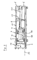
- FIG. 2 By moving apart of the components but also other elements are clearly visible.
- a cylinder 3 is supported on a stationary support 6.
- the support 6 is in turn connected to the front and rear plates of the pressing channel 1.
- Another cylinder 4 is arranged lying behind the cylinder 3.
- the cylinders 3 and 4 end with their piston rods left to a yoke 7 and are fixed there.
- a further cylinder 5 is arranged, the piston rod to the left of the yoke 7 can be seen.
- This piston rod is attached to the press carriage 18.
- the yoke 7 - in contrast to the cited prior art - has no support on the bottom 10 of the baler or on lateral walls. According to the invention, the yoke is guided in the press carriage 18.
- FIG. 2 it can also be seen that two cover plates 12, 13 close the filling opening 8.
- the cover plate 12 is connected to the left with the press plate 2 or the press carriage 18, and the cover plate 13 via a holder 23 to the housing of the cylinder 5. Actively, this cover plate 13 is thus connected to the yoke 7. At the point of overlap of the cover plates 12, 13, the cover plates 12, 13 slide on each other during pressing stroke and idle stroke.
- FIGS. 3 to 5 the press carriage 18 is shown together with the cylinders 3, 4, 5 and the cover plates 12, 13 in different positions of the cylinders 3, 4, 5.
- the relative arrangement of the cylinder 3, 4, 5 is clear to each other.
- the cylinders 3, 4, 5 are all three cylinders in the retracted state, ie that this is the position that exists when filling the press channel 1.
- the cylinders 3, 4 are completely extended and the cylinder 5 is slightly extended.
- the pressing plate 2 and the pressing carriage 18 are fully extended. Only in this figure can one recognize that the yoke 7 is supported on a surface 25 within the press carriage 18. As a result, the entire cylinder system has such a stiffness, so that the yoke 7 requires no further support - for example on the walls or at the bottom of the baler.
- the two cover plates 12 and 13 can be seen.
- a so-called triangular bar 26th attached, the deposits on the lower cover plate 12 can scrape. If this triangular bar 26 were not present, then - in particular stiff material - could slide between the plates 12, 13, so that the upper cover plate 13 lifts, which could then lead to an accident case.
- the triangular strip 26 is made of a wear-resistant plastic or non-ferrous metal material to keep the friction between the cover plates 12, 13 low.
- the stroke of the / the first extending cylinder 3, 4, 5 accomplished about 35 to 70% of the total stroke.
- a first partial stroke of a pressing stroke that is, when the filled waste material, especially cardboard and the like. Voluminous waste, is first pushed together once, so "the air” is pressed out, be performed in the manner of a quick lift.
- the cycle time for the production of a bale is significantly shortened; In addition, the energy required for this partial lift is lower.
- baling press according to the invention can also be used for a vertical installation because of their shorter length.
Landscapes
- Engineering & Computer Science (AREA)
- Mechanical Engineering (AREA)
- Physics & Mathematics (AREA)
- Fluid Mechanics (AREA)
- Basic Packing Technique (AREA)
- Processing Of Solid Wastes (AREA)
- Auxiliary Devices For And Details Of Packaging Control (AREA)
Abstract
Description
- Die Erfindung betrifft ein Verfahren zum Verdichten von voluminösen, sperrigen und/oder komprimierbaren Abfallstoffen zu einem kompakten Pressgut in einer Ballenpresse gemäß dem Oberbegriff des Anspruches 1. Ferner betrifft die Erfindung eine Ballenpresse zur Durchführung des Verfahrens gemäß dem Oberbegriff des Anspruches 5.
- Die meisten modernen Ballenpressen , die weitgehend für den Dauerbetrieb vorgesehen sind, erfordern einen störungsfreien, zeit-und/oder arbeitssparenden automatischen Betrieb der Ballenpresse, insbesondere dann, wenn unterschiedlich voluminöse und sperrige Abfallstoffe, wie Papier, Pappe, Kunststoffe oder ähnliche Materialien zu gepressten, kompakten Ballen verarbeitet werden müssen.
- Aus Gründen der Effizienz werden Ballenpressen auch immer größer gebaut, so dass sie in diesem Zuge auch immer länger werden. Dieses erklärt sich dadurch, dass der Presswagen beim Befüllen des Presskanals der Ballenpresse, hinter den einen Rand der Einfüllöffnung zurückgezogen sein muss. Da das Pressgut im Allgemeinen aber elastisch ist, würde es nach dem Pressen unter Umständen in den Bereich der Einfüllöffnung zurückfedern, welches das Aufnahmevermögen der Einfüllöffnung reduzieren würde. Um dieses zu verhindern, muss der Presswagen beim Pressen deutlich über den anderen Rand der Einfüllöffnung hinausgehen. Wird dieses mit nur einem hydraulischen Zylinder realisiert, so würde die Ballenpresse an dem antriebsseitigen Ende lang ausbauen. Teleskop-Zylinder, also Zylinder mit mindestens zwei ausfahrbaren Stufen, wären an ihrer inneren Stufe verhältnismäßig dünn. Dieses würde die Gefahr einer hohen Knickbelastung bedeuten. Außerdem wären Teleskop-Zylinder nachteilig, weil sie sehr kostenintensiv sind.
- Aus der deutschen Offenlegungsschrift
1 924 389 ist eine horizontal angeordnete Müllpresse bekannt, die mit zwei einstufigen Hydraulikzylindern arbeitet. Beide Zylinder sind an ihren Gehäusen mittels Laschen untereinander verbunden. Die eine Kolbenstange wirkt hierbei gegen eine ortsfeste Abstützung, während die andere Kolbenstange gegen eine Pressplatte drückt. Die Gesamtlänge des hydraulischen Antriebs entspricht hierbei im Wesentlichen nur der Länge eines Zylinders. Die hydraulischen Anschlüsse sind hierbei derart angeordnet, dass beim Arbeitshub oder beim Leerhub beide Zylinder gleichzeitig arbeiten. - Aus dem deutschen Gebrauchsmuster
DE 87 17 589 U1 ist eine Ballenpresse bekannt, bei der ein oder mehrere Zylinder sich mit ihrem einen Ende an einer ortsfesten Abstützung, und an ihrem anderen Ende an einem Joch abstützen. Im Falle mehrerer Zylinder können diese rotationssymmetrisch um die Mittenachse einer Pressplatte/eines Presswagens angeordnet sein. An diesem Joch ist wiederum ein Zylinder angebracht, der zentrisch auf die Pressplatte wirkt. Das freie Ende dieses Zylinders wird mit Führungsnuten und Gleitsteinen zusätzlich seitlich geführt. Das Joch ist - so wie die Pressplatte - mit Laufrollen versehen, die auf dem Boden der Ballenpresse ihre Lauffläche haben. Ferner wird beschrieben, dass die Zylinder vor und hinter dem Joch gleichzeitig mit einem Druckmittel beaufschlagt werden. - Die Konstruktionen aus dem Stand der Technik weisen sich dadurch aus, dass sie hohe Biegekräfte auf die Kolbenstangen ausüben. Weil dort die hydraulischen Leitungen nach dem Ventil einfach nur verzweigen, ohne einen Ölstromteiler oder Ähnliches aufzuweisen, kann bei den Hüben mal der eine Zylinder oder die eine Zylindergruppe ausfahren bzw. einfahren und dann mal der andere oder die andere. Dieses führt zu einem undefinierten Arbeitsablauf.
- Es ist deshalb Aufgabe der Erfindung eine Ballenpresse bereitzustellen, die die genannten Nachteile aus dem Stand der Technik nicht aufweist.
- Diese Aufgabe wird erfindungsgemäß durch ein Verfahren zum Verdichten von voluminösen Abfallstoffen mit den Merkmalen des Anspruches 1 gelöst; zur Durchführung des Verfahrens wird eine erfindungsgemäße Ballenpresse mit den Merkmalen des Anspruches 5 bereitgestellt.
- Vorteilhafte Ausgestaltungen des Verfahrens und der Ballenpresse werden mit den Ansprüchen 2 bis 4 bzw. 6 bis 13 aufgezeigt.
- Gemäß dem erfindungsgemäßen Verfahren werden die Zylinder bzw. die Gruppen von Zylindern, den so genannten Zylindereinheiten, derart angesteuert, dass sie nacheinander ausgefahren werden. Dieses hat den Vorteil, dass definierte Kolbenbewegungen ermöglicht werden. Dieses ist unter anderem auch für andere Vorgänge an der Ballenpresse von Vorteil. So kann dieses für die Steuerung von Deckplatten für die Einfüllöffnung verwendet werden, wie Nachfolgend noch weiter ausgeführt wird.
- Weil konstruktiv zwei Zylinder zwischen einer ortsfesten Abstützung und der gemeinsamen Montageplatte - einem Joch - angeordnet sind, verleiht dieses dem Gesamtsystem derart Stabilität, so dass das Joch keine seitliche Führung benötigt. Der Zylinder zwischen dem Joch und dem Presswagen der Ballenpresse wird dadurch ebenfalls ausreichend geführt. Das Joch selbst wird lediglich innerhalb des Presswagen geführt. Im Rahmen der Erfindung ist es dabei nicht erforderlich, dass dieser Zylinder tatsächlich in der Mitte der Pressplatte drückt. Je nach der Beschaffenheit des Pressgutes und der Befüllung in den Presskanal kann der Druckmittelpunkt auch oberhalb oder unterhalb der geometrischen Mitte liegen.
- Nachfolgend wird die Erfindung anhand der Figuren im Weiteren und näher erläutert. Es zeigen in schematischer Darstellung:
- Figur 1
- einen Längsschnitt durch den Presskanal einer Ballenpresse mit dem Presswagen in der Füllstellung;
- Figur 2
- einen Längsschnitt durch den Presskanal einer Ballenpresse mit dem Presswagen in der Press- Endstellung;
- Figur 3
- den Presswagen mit den Zylindern in der Füllstellung der Ballenpresse;
- Figur 4
- den Presswagen mit den Zylindern in einer mittleren Stellung der Ballenpresse;
- Figur 5
- den Presswagen mit den Zylindern in der Press- Endstellung der Ballenpresse;
- Figur 6
- eine Teilansicht der Ballenpresse im Bereich der Deckplatten.
- Dieser Figurenbeschreibung soll vorangestellt werden, dass hier verwendete Begriffe wie "oben", "unten", rechts" oder "links" und dergleichen sich lediglich auf die Darstellungen in den Figuren beziehen und von den Orientierungsangaben an der realen Erfindung abweichen können.
- In der
Figur 1 ist ein Presskanal 1 bzw. ein Presskasten einer Ballenpresse aufgeschnitten dargestellt. Ein darin angeordneter Presswagen 18 mit einer daran auf der Pressseite angeordneten Pressplatte 2 ist jedoch nicht geschnitten dargestellt. Der Presswagen 18 läuft auf unteren Laufrollen 15 auf in derFigur 1 nicht sichtbaren Laufschienen. Diese Schienen werden durch Schienenräumer 16 sauber gehalten. Der Presswagen 18 weist aber auch obere Laufrollen 17 auf, die an einer oberen Laufschiene 20 geführt werden. Wenn der Presswagen 18 nach links in Pressrichtung 11 bewegt wird, so durchfährt er den Bereich der Einfüllöffnung 8. Der Presswagen 18 besitzt an seinem linken, oberen Ende ein Messer 19. Dieses Messer 19 schneidet während des Pressens in Verbindung mit dem am Presskanal 1 fest angeordneten Messer 21 nach oben überstehendes Pressgut ab. In dem Bereich zwischen dem Messer 21 und einer Auslassöffnung 9, oder, in Pressrichtung 11 betrachtet, hinter der Auslassöffnung 9 kann eine - hier nicht dargestellte - Umreifungseinrichtung angeordnet sein. Im weiteren Verlauf der Pressrichtung 11 kann eine weitere Presseinrichtung angeordnet sein, die auf zumindest zwei gegenüberliegende Flächen der Ballen einwirkt, die auch schon mit den Seiten Wänden des Presskanals 1 Berührung gehabt haben. Die Presseinrichtung besteht im Allgemeinen aus leicht keilförmig zueinander einstellbaren Seitenflächen. Durch diese Einrichtung wird ein Weiterrutschen der Ballen in Pressrichtung 11 erschwert, wodurch sich zwischen diesen Ballen und dem Presswagen 18 der gewünschte Druck im Pressgut aufbauen lässt. Diese keilförmige Presseinrichtung kann mittels der Befestigungselemente 22 mit dem Presskanal 1 verbunden werden. - Mit der
Figur 2 wird der Presskanal 1 in der Situation gezeigt, in der der Presswagen 18 bereits an dem feststehenden Messer 21 vorbei gefahren ist. Es ist die linke Extremposition des Presswagens 18 bzw. der Pressplatte 1. Das deutliche Vorbeifahren der Pressplatte 1 ist insofern wichtig, weil beim Zurückfahren des Presswagens 18 das gegebenenfalls elastische Pressgut zwar wieder in Richtung Einfüllöffnung 8 zurückfedert, aber nicht einen Teil der Einfüllöffnung 8 ausfüllt. - Mit einer strichpunktierten Linie 24 ist der weitere, ausgangsseitige Verlauf des Presskanals 1 nur angedeutet, da er für die weitere Beschreibung der vorliegenden Erfindung nicht relevant ist. In der
Figur 2 werden durch das Auseinanderfahren der Bauteile aber auch weitere Elemente deutlicher sichtbar. Man kann so z.B. sehen, dass sich ein Zylinder 3 an einer ortsfesten Abstützung 6 abstützt. Die Abstützung 6 ist wiederum mit den vorderen und rückwärtigen Platten des Presskanals 1 verbunden. Ein weiterer Zylinder 4 ist hinter dem Zylinder 3 liegend angeordnet. Die Zylinder 3 und 4 enden mit ihren Kolbenstangen links an einem Joch 7 und sind dort auch fixiert. Zwischen den Zylindern 3, 4 ist ein weiterer Zylinder 5 angeordnet, dessen Kolbenstange links neben dem Joch 7 zu sehen ist. Diese Kolbenstange ist an dem Presswagen 18 angebracht. Deutlich kann man hier auch erkennen, dass das Joch 7 - im Gegensatz zum zitierten Stand der Technik - keine Abstützung am Boden 10 der Ballenpresse oder an seitlichen Wänden aufweist. Gemäß der Erfindung wird das Joch im Presswagen 18 geführt. - In der
Figur 2 kann man auch erkennen, dass zwei Deckplatten 12, 13 die Einfüllöffnung 8 verschließen. Die Deckplatte 12 ist links mit der Pressplatte 2 bzw. dem Presswagen 18, und die Deckplatte 13 über einen Halter 23 mit dem Gehäuse des Zylinders 5 verbunden. Wirkmäßig ist diese Deckplatte 13 also mit dem Joch 7 verbunden. An der überlappungsstelle der Deckplatten 12, 13 gleiten die Deckplatten 12, 13 bei Presshub und Leerhub aufeinander. - Mit den
Figuren 3 bis 5 wird der Presswagen 18 zusammen mit den Zylindern 3, 4, 5 und den Deckplatten 12, 13 in verschiedenen Stellungen der Zylinder 3, 4, 5 gezeigt. Durch die perspektivische Darstellung wird auch die relative Anordnung der Zylinder 3, 4, 5 zueinander deutlich. In derFigur 3 sind alle drei Zylinder im eingefahrenen Zustand, d.h. dass dieses die Stellung ist, die beim Befüllen des Presskanals 1 existiert. In derFigur 4 sind die Zylinder 3, 4 vollständig und der Zylinder 5 geringfügig ausgefahren. In derFigur 5 hingegen sind die Pressplatte 2 bzw. der Presswagen 18 voll ausgefahren. Erst in dieser Figur kann man erkennen, dass das Joch 7 auf einer Fläche 25 innerhalb des Presswagens 18 abgestützt ist. Dadurch hat das gesamte Zylindersystem eine derartige Steifigkeit, so dass das Joch 7 keine weitere Abstützung - beispielsweise an den Wänden oder am Boden der Ballenpresse benötigt. - Im Vergleich mit der
Figur 3 wird deutlich, dass es vorteilhaft ist, wenn die Deckplatten 12, 13 teleskopartig gestaltet sind, weil so die Deckplatte 12, 13 in Längsrichtung des Presskanals 1 auch nicht länger sind als die eingefahrenen Zylinder 3, 4, 5. Dieses unterstützt die kompakte Bauweise der erfindungsgemäßen Ballenpresse. - In der
Figur 6 sind die beiden Deckplatten 12 und 13 zu sehen. An der der oberen Deckplatte 13 ist eine so genannte Dreiecksleiste 26 angebracht, die Ablagerungen auf der unteren Deckplatte 12 abschaben kann. Wäre diese Dreiecksleiste 26 nicht vorhanden, so könnte sich - insbesondere steifes Material - zwischen die Platten 12, 13 schieben, sodass sich die obere Deckplatte 13 anhebt, wodurch es dann zu einem Havarie-Fall kommen könnte. Vorzugsweise wird die Dreiecksleiste 26 aus einem verschleißfesten Kunststoff oder NE-Metall-Werkstoff gefertigt, um die Reibung zwischen den Deckplatten 12, 13 gering zu halten. - In einer Ausgestaltung der Erfindung bewerkstelligt der Hub der/die zuerst ausfahrenden Zylinder 3, 4, 5 etwa 35 bis 70% des Gesamthubes. Damit kann nach der Erfindung ein erster Teilhub eines Presshubes, also wenn das eingefüllte Abfallmaterial, insbesondere Kartonagen und dgl. voluminöser Abfall, zunächst erst einmal zusammen geschoben wird, also "die Luft" rausgepresst wird, in Art eines Schnellhubes ausgeführt werden. Damit wird die Taktzeit für die Herstellung eines Ballens wesentlich verkürzt; zudem ist der Energiebedarf für diesen Teilhub geringer.
- Im Rahmen der Erfindung soll noch darauf hingewiesen werden, dass die erfindungsgemäße Ballenpresse wegen ihrer kürzeren Baulänge auch für eine vertikale Aufstellung Anwendung finden kann.
- Bexugszeichenliste
- 1
- Presskanal
- 2
- Pressplatte
- 3
- Zylinder
- 4
- Zylinder
- 5
- Zylinder
- 6
- Abstützung
- 7
- Joch
- 8
- Einfüllöffnung
- 9
- Auslassöffnung
- 10
- Boden des Presskanals
- 11
- Pressrichtung
- 12
- Deckplatte
- 13
- Deckplatte
- 14
- Fuß
- 15
- untere Laufrollen
- 16
- Schienenräumer
- 17
- obere Laufrollen
- 18
- Presswagen
- 19
- Messer an der Pressplatte
- 20
- obere Laufschiene
- 21
- festes Messer
- 22
- Befestigungselemente
- 23
- Halter
- 24
- weiterer Verlauf des Presskanals
- 25
- Fläche
- 26
- Dreiecksleiste
Claims (13)
- Verfahren zum Verdichten von voluminösen, sperrigen und/oder komprimierbaren Abfallstoffen zu einem kompakten Pressgut in einer Ballenpresse, mit einem Presskanal (1) und eines in Längserstreckung des Presskanals bewegbaren Presswagens (18), der mittels mehrerer hydraulisch Zylinder (3, 4, 5) bewegt wird und die Zylinder (3, 4, 5) eine erste Zylindereinheit und eine zweite Zylindereinheit bilden, wobei die erste Zylindereinheit zwischen einer Abstützung (6) und einem Joch (7) mit den Zylindern (3, 4) und die zweite Zylindereinheit zwischen dem Joch und der Pressplatte (2) mit Zylindern (5) angeordnet ist,
dadurch gekennzeichnet,
dass die erste und die zweite Zylindereinheit seriell - also nacheinander - arbeiten. - Verfahren nach Anspruch 1,
dadurch gekennzeichnet,
dass in der ersten Zylindereinheit mindestens zwei Zylinder (3, 4) und in der zweiten Zylindereinheit mindestens ein Zylinder (5) wirken. - Verfahren nach Anspruch 1 oder 2,
dadurch gekennzeichnet,
dass zum Pressen zunächst die erste Zylindereinheit (Zylindern 3, 4) und dann erst die zweite Zylindereinheit (Zylinder 5) ausfährt. - Verfahren nach mindestens einem der Ansprüche 1 bis 3, dadurch gekennzeichnet,
dass beim Zurückfahren des Presswagens (18) in seine Ruheposition zunächst die zweite Zylindereinheit und dann erst die erste Zylindereinheit einfährt. - Ballenpresse zur Durchführung des Verfahrens nach Anspruch 1 bis 4 mit einem Presskanal, einer Einfüllöffnung (8), einer Auslassöffnung (9) und einer an einem Presswagen (18) befindlichen Pressplatte (2), mehreren Zylindern (3, 4, 5) zwischen einer ortsfesten Abstützung (6) und dem Presswagen (18),
dadurch gekennzeichnet,
dass zwischen der Abstützung (6) und einem im Presswagen (18) geführten Joch (7) zwei Zylinder (3, 4) und zwischen dem Joch (7) und dem Presswagen (18) mindestens ein weiterer Zylinder (5) angeordnet ist. - Ballenpresse nach Anspruch 5,
dadurch gekennzeichnet,
dass beide Zylinder (3, 4) zur Längsachse des Presskanals (1) parallel sind und zum Boden (10) des Presskanals (1) den gleichen Abstand aufweisen. - Ballenpresse nach einem der Ansprüche 5 oder 6,
dadurch gekennzeichnet,
dass an dem der Presswagen (18) abgewandten Ende des Presskanals (1) eine Umreifungseinrichtung angeordnet ist. - Ballenpresse nach mindestens Anspruch 7,
dadurch gekennzeichnet,
dass - in Pressrichtung (11) betrachtet - nach der Umreifungseinrichtung eine Presseinrichtung angeordnet ist, die auf mindestens zwei, einander gegenüberliegenden, Flächen der Ballen einwirkt, die schon mit den inneren Oberflächen des Presskanals (1) Berührung hatten. - Ballenpresse nach mindestens einem der Ansprüche 5 bis 8, dadurch gekennzeichnet,
dass die Einfüllöffnung (8) mit mindestens einer Deckplatte (12, 13) verschließbar ist. - Ballenpresse nach Anspruch 9,
dadurch gekennzeichnet,
dass zwei Deckplatten (12, 13) vorhanden sind, wobei eine Deckplatte (12) mit der Pressplatte (2) und eine Deckplatte (13) mit dem Gehäuse des Zylinders (5) verbunden ist, der zwischen Joch (7) und Pressplatte (2) angeordnet ist. - Ballenpresse nach mindestens einem der Ansprüche 5 bis 10, dadurch gekennzeichnet,
dass der Presskanal (1) vertikal angeordnet ist. - Ballenpresse nach mindestens einem der Ansprüche 5 bis 11, dadurch gekennzeichnet,
dass der/die zuerst ausfahrenden Zylinder (3, 4, 5) 35 bis 70% des Gesamthubes bewerkstelligen. - Ballenpresse nach mindestens einem der Ansprüche 5 bis 12, dadurch gekennzeichnet,
dass an der Unterseite der oberen Deckplatte (13) eine Dreiecksleiste (26) angebracht ist, die auf der Oberseite der unteren Deckplatte (12) gleitet.- hierzu 4 Blatt Zeichnungen -
Applications Claiming Priority (1)
| Application Number | Priority Date | Filing Date | Title |
|---|---|---|---|
| DE102009040508.9A DE102009040508B4 (de) | 2009-09-02 | 2009-09-02 | Ballenpresse |
Publications (3)
| Publication Number | Publication Date |
|---|---|
| EP2292418A2 true EP2292418A2 (de) | 2011-03-09 |
| EP2292418A3 EP2292418A3 (de) | 2012-04-18 |
| EP2292418B1 EP2292418B1 (de) | 2017-05-10 |
Family
ID=43033230
Family Applications (1)
| Application Number | Title | Priority Date | Filing Date |
|---|---|---|---|
| EP10009132.1A Active EP2292418B1 (de) | 2009-09-02 | 2010-09-02 | Ballenpresse |
Country Status (5)
| Country | Link |
|---|---|
| EP (1) | EP2292418B1 (de) |
| DE (1) | DE102009040508B4 (de) |
| DK (1) | DK2292418T3 (de) |
| ES (1) | ES2628103T3 (de) |
| PL (1) | PL2292418T3 (de) |
Cited By (4)
| Publication number | Priority date | Publication date | Assignee | Title |
|---|---|---|---|---|
| ITBO20110259A1 (it) * | 2011-05-09 | 2012-11-10 | Gian Carlo Pantucci | Dispositivo compattatore |
| EP2559548A1 (de) | 2011-08-17 | 2013-02-20 | G. Gillard SAS | Abfallkompaktierungszelle, die in einen Abfallbehälter integriert oder mit ihm verbunden ist |
| CN113619183A (zh) * | 2021-08-13 | 2021-11-09 | 晋江市恒里机械配件有限公司 | 一种高自动化卧式废纸打包装置及工作方法 |
| CN114009226A (zh) * | 2021-12-06 | 2022-02-08 | 王有琴 | 草料打捆机 |
Families Citing this family (1)
| Publication number | Priority date | Publication date | Assignee | Title |
|---|---|---|---|---|
| DE102013014074B3 (de) * | 2013-08-15 | 2014-11-27 | Hermann Schwelling | Ballenpresse |
Family Cites Families (12)
| Publication number | Priority date | Publication date | Assignee | Title |
|---|---|---|---|---|
| GB946924A (en) * | 1960-04-29 | 1964-01-15 | Erwin Traband | Improvements relating to baling-presses |
| GB1062641A (en) * | 1963-01-15 | 1967-03-22 | Walkers And County Gars Ltd | Improvements in or relating to long stroke presses |
| US3252600A (en) * | 1964-06-29 | 1966-05-24 | Lodal Inc | Cycling compactor and ejection system for bulk material |
| US3541949A (en) * | 1968-05-09 | 1970-11-24 | Auto Pak Co | Apparatus for compacting material into drums or bags |
| FR2613664B1 (fr) * | 1987-04-08 | 1996-08-30 | Fialaire Andre | Dispositif permettant de diminuer la longueur et d'augmenter la charge d'un compacteur a dechets, mobile |
| DE8717589U1 (de) * | 1987-10-13 | 1989-05-03 | Maschinenfabrik Bermatingen GmbH & Co, 7775 Bermatingen | Ballenpresse |
| DE3926907A1 (de) * | 1989-08-16 | 1991-02-21 | Paals Packpressen Fabrik Gmbh | Ballenpresse |
| US5690025A (en) * | 1996-01-16 | 1997-11-25 | Hawkins; Bobby Leonard | Trash receptacle and compactor for use in public areas and method |
| DE19834955B4 (de) * | 1998-08-03 | 2008-02-07 | Linde Material Handling Gmbh | Hydrostatisches Antriebssystem |
| US6131391A (en) * | 1998-12-23 | 2000-10-17 | Caterpillar Inc. | Control system for controlling the speed of a hydraulic motor |
| US6467264B1 (en) * | 2001-05-02 | 2002-10-22 | Husco International, Inc. | Hydraulic circuit with a return line metering valve and method of operation |
| DE10339004B4 (de) * | 2003-08-25 | 2006-09-28 | Wieber, Christian, Dipl.-Ing.(FH), Batu Caves | Hydraulische Presse |
-
2009
- 2009-09-02 DE DE102009040508.9A patent/DE102009040508B4/de not_active Expired - Fee Related
-
2010
- 2010-09-02 EP EP10009132.1A patent/EP2292418B1/de active Active
- 2010-09-02 ES ES10009132.1T patent/ES2628103T3/es active Active
- 2010-09-02 DK DK10009132.1T patent/DK2292418T3/en active
- 2010-09-02 PL PL10009132T patent/PL2292418T3/pl unknown
Cited By (6)
| Publication number | Priority date | Publication date | Assignee | Title |
|---|---|---|---|---|
| ITBO20110259A1 (it) * | 2011-05-09 | 2012-11-10 | Gian Carlo Pantucci | Dispositivo compattatore |
| EP2559548A1 (de) | 2011-08-17 | 2013-02-20 | G. Gillard SAS | Abfallkompaktierungszelle, die in einen Abfallbehälter integriert oder mit ihm verbunden ist |
| FR2979073A1 (fr) * | 2011-08-17 | 2013-02-22 | Gillard Sas G | Cellule de compactage de dechets reliee ou integree a un conteneur de dechets |
| CN113619183A (zh) * | 2021-08-13 | 2021-11-09 | 晋江市恒里机械配件有限公司 | 一种高自动化卧式废纸打包装置及工作方法 |
| CN113619183B (zh) * | 2021-08-13 | 2024-05-03 | 晋江市恒里机械配件有限公司 | 一种高自动化卧式废纸打包装置及工作方法 |
| CN114009226A (zh) * | 2021-12-06 | 2022-02-08 | 王有琴 | 草料打捆机 |
Also Published As
| Publication number | Publication date |
|---|---|
| PL2292418T3 (pl) | 2017-09-29 |
| DE102009040508B4 (de) | 2021-04-08 |
| DE102009040508A1 (de) | 2011-04-21 |
| ES2628103T3 (es) | 2017-08-01 |
| EP2292418A3 (de) | 2012-04-18 |
| EP2292418B1 (de) | 2017-05-10 |
| DK2292418T3 (en) | 2017-07-31 |
Similar Documents
| Publication | Publication Date | Title |
|---|---|---|
| EP2292418B1 (de) | Ballenpresse | |
| EP3037252A2 (de) | Hub-/kippeinrichtung zum entleeren eines sammelbehälters in eine ballenpresse nebst ballenpresse und verfahren zum befüllen der ballenpresse | |
| EP0042580A1 (de) | Vorrichtung zum Verdichten von Müll in offenen Containern | |
| DE19644574C2 (de) | Ballenpresse | |
| DE2716215A1 (de) | Vorrichtung zum ablegen von runden metallischen stangen und rohren | |
| DE102007013382A1 (de) | Verfahren zum Herstellen eines Pressballens und Vorrichtung zum Herstellen von Pressballen | |
| DE2554520C3 (de) | Vorrichtung zum Einbringen von Müll o.dgl. in einen Sammelbehälter | |
| DE102012008554A1 (de) | Kanalballenpresse | |
| EP4069504B1 (de) | Ballenpresse sowie verfahren zum betreiben der ballenpresse | |
| DE2457768A1 (de) | Presse | |
| DE2914448A1 (de) | Vorrichtung zum verschieben der filterplatten einer filterpresse | |
| DE102014116016A1 (de) | Ballenpresse | |
| DE102012202437A1 (de) | Presse zum Herstellen von Pressballen, Abbindeeinrichtung und Nachpresseinrichtung | |
| DE9403005U1 (de) | Mehrteiliges Bunkerboden-Austragsystem | |
| DE3023508C1 (de) | Vorrichtung zum Verdichten von aus Verpackungsmaterial und leicht preßbaren Abfällen bestehendem Müll | |
| DE202013012192U1 (de) | Kanalballenpresse | |
| DE3734555A1 (de) | Ballenpresse | |
| DE20314460U1 (de) | Ballenpresse mit vertikal verschiebbarer Preßplatte | |
| DE2745864C2 (de) | Ballenpresse | |
| DE202008016044U1 (de) | Presse mit einer Schneideinrichtung | |
| DE2654751C3 (de) | Schrottschere | |
| DE10106094B4 (de) | Ballenpresse | |
| DE10139450A1 (de) | Ballenpresse | |
| CH403629A (de) | Müll-Ausstossvorrichtung an Müllwagen | |
| DE2409491C3 (de) | Müllpresse für sperriges Gut, Haushaltsmüll u.dgl |
Legal Events
| Date | Code | Title | Description |
|---|---|---|---|
| PUAI | Public reference made under article 153(3) epc to a published international application that has entered the european phase |
Free format text: ORIGINAL CODE: 0009012 |
|
| AK | Designated contracting states |
Kind code of ref document: A2 Designated state(s): AL AT BE BG CH CY CZ DE DK EE ES FI FR GB GR HR HU IE IS IT LI LT LU LV MC MK MT NL NO PL PT RO SE SI SK SM TR |
|
| AX | Request for extension of the european patent |
Extension state: BA ME RS |
|
| PUAL | Search report despatched |
Free format text: ORIGINAL CODE: 0009013 |
|
| AK | Designated contracting states |
Kind code of ref document: A3 Designated state(s): AL AT BE BG CH CY CZ DE DK EE ES FI FR GB GR HR HU IE IS IT LI LT LU LV MC MK MT NL NO PL PT RO SE SI SK SM TR |
|
| AX | Request for extension of the european patent |
Extension state: BA ME RS |
|
| RIC1 | Information provided on ipc code assigned before grant |
Ipc: B30B 9/30 20060101AFI20120312BHEP Ipc: B30B 1/34 20060101ALI20120312BHEP Ipc: B30B 1/36 20060101ALI20120312BHEP |
|
| 17P | Request for examination filed |
Effective date: 20121018 |
|
| 17Q | First examination report despatched |
Effective date: 20160629 |
|
| GRAP | Despatch of communication of intention to grant a patent |
Free format text: ORIGINAL CODE: EPIDOSNIGR1 |
|
| INTG | Intention to grant announced |
Effective date: 20170116 |
|
| GRAS | Grant fee paid |
Free format text: ORIGINAL CODE: EPIDOSNIGR3 |
|
| GRAA | (expected) grant |
Free format text: ORIGINAL CODE: 0009210 |
|
| AK | Designated contracting states |
Kind code of ref document: B1 Designated state(s): AL AT BE BG CH CY CZ DE DK EE ES FI FR GB GR HR HU IE IS IT LI LT LU LV MC MK MT NL NO PL PT RO SE SI SK SM TR |
|
| REG | Reference to a national code |
Ref country code: GB Ref legal event code: FG4D Free format text: NOT ENGLISH |
|
| REG | Reference to a national code |
Ref country code: AT Ref legal event code: REF Ref document number: 891855 Country of ref document: AT Kind code of ref document: T Effective date: 20170515 Ref country code: CH Ref legal event code: EP |
|
| REG | Reference to a national code |
Ref country code: IE Ref legal event code: FG4D Free format text: LANGUAGE OF EP DOCUMENT: GERMAN |
|
| REG | Reference to a national code |
Ref country code: DE Ref legal event code: R096 Ref document number: 502010013570 Country of ref document: DE |
|
| REG | Reference to a national code |
Ref country code: DK Ref legal event code: T3 Effective date: 20170725 |
|
| REG | Reference to a national code |
Ref country code: ES Ref legal event code: FG2A Ref document number: 2628103 Country of ref document: ES Kind code of ref document: T3 Effective date: 20170801 |
|
| REG | Reference to a national code |
Ref country code: SE Ref legal event code: TRGR |
|
| REG | Reference to a national code |
Ref country code: NL Ref legal event code: MP Effective date: 20170510 |
|
| REG | Reference to a national code |
Ref country code: LT Ref legal event code: MG4D Ref country code: FR Ref legal event code: PLFP Year of fee payment: 8 |
|
| PG25 | Lapsed in a contracting state [announced via postgrant information from national office to epo] |
Ref country code: LT Free format text: LAPSE BECAUSE OF FAILURE TO SUBMIT A TRANSLATION OF THE DESCRIPTION OR TO PAY THE FEE WITHIN THE PRESCRIBED TIME-LIMIT Effective date: 20170510 Ref country code: GR Free format text: LAPSE BECAUSE OF FAILURE TO SUBMIT A TRANSLATION OF THE DESCRIPTION OR TO PAY THE FEE WITHIN THE PRESCRIBED TIME-LIMIT Effective date: 20170811 Ref country code: FI Free format text: LAPSE BECAUSE OF FAILURE TO SUBMIT A TRANSLATION OF THE DESCRIPTION OR TO PAY THE FEE WITHIN THE PRESCRIBED TIME-LIMIT Effective date: 20170510 Ref country code: HR Free format text: LAPSE BECAUSE OF FAILURE TO SUBMIT A TRANSLATION OF THE DESCRIPTION OR TO PAY THE FEE WITHIN THE PRESCRIBED TIME-LIMIT Effective date: 20170510 Ref country code: NO Free format text: LAPSE BECAUSE OF FAILURE TO SUBMIT A TRANSLATION OF THE DESCRIPTION OR TO PAY THE FEE WITHIN THE PRESCRIBED TIME-LIMIT Effective date: 20170810 |
|
| PG25 | Lapsed in a contracting state [announced via postgrant information from national office to epo] |
Ref country code: IS Free format text: LAPSE BECAUSE OF FAILURE TO SUBMIT A TRANSLATION OF THE DESCRIPTION OR TO PAY THE FEE WITHIN THE PRESCRIBED TIME-LIMIT Effective date: 20170910 Ref country code: NL Free format text: LAPSE BECAUSE OF FAILURE TO SUBMIT A TRANSLATION OF THE DESCRIPTION OR TO PAY THE FEE WITHIN THE PRESCRIBED TIME-LIMIT Effective date: 20170510 Ref country code: LV Free format text: LAPSE BECAUSE OF FAILURE TO SUBMIT A TRANSLATION OF THE DESCRIPTION OR TO PAY THE FEE WITHIN THE PRESCRIBED TIME-LIMIT Effective date: 20170510 Ref country code: BG Free format text: LAPSE BECAUSE OF FAILURE TO SUBMIT A TRANSLATION OF THE DESCRIPTION OR TO PAY THE FEE WITHIN THE PRESCRIBED TIME-LIMIT Effective date: 20170810 |
|
| PG25 | Lapsed in a contracting state [announced via postgrant information from national office to epo] |
Ref country code: RO Free format text: LAPSE BECAUSE OF FAILURE TO SUBMIT A TRANSLATION OF THE DESCRIPTION OR TO PAY THE FEE WITHIN THE PRESCRIBED TIME-LIMIT Effective date: 20170510 Ref country code: EE Free format text: LAPSE BECAUSE OF FAILURE TO SUBMIT A TRANSLATION OF THE DESCRIPTION OR TO PAY THE FEE WITHIN THE PRESCRIBED TIME-LIMIT Effective date: 20170510 Ref country code: CZ Free format text: LAPSE BECAUSE OF FAILURE TO SUBMIT A TRANSLATION OF THE DESCRIPTION OR TO PAY THE FEE WITHIN THE PRESCRIBED TIME-LIMIT Effective date: 20170510 Ref country code: SK Free format text: LAPSE BECAUSE OF FAILURE TO SUBMIT A TRANSLATION OF THE DESCRIPTION OR TO PAY THE FEE WITHIN THE PRESCRIBED TIME-LIMIT Effective date: 20170510 |
|
| REG | Reference to a national code |
Ref country code: DE Ref legal event code: R097 Ref document number: 502010013570 Country of ref document: DE |
|
| PG25 | Lapsed in a contracting state [announced via postgrant information from national office to epo] |
Ref country code: IT Free format text: LAPSE BECAUSE OF FAILURE TO SUBMIT A TRANSLATION OF THE DESCRIPTION OR TO PAY THE FEE WITHIN THE PRESCRIBED TIME-LIMIT Effective date: 20170510 Ref country code: SM Free format text: LAPSE BECAUSE OF FAILURE TO SUBMIT A TRANSLATION OF THE DESCRIPTION OR TO PAY THE FEE WITHIN THE PRESCRIBED TIME-LIMIT Effective date: 20170510 |
|
| PLBE | No opposition filed within time limit |
Free format text: ORIGINAL CODE: 0009261 |
|
| STAA | Information on the status of an ep patent application or granted ep patent |
Free format text: STATUS: NO OPPOSITION FILED WITHIN TIME LIMIT |
|
| 26N | No opposition filed |
Effective date: 20180213 |
|
| REG | Reference to a national code |
Ref country code: CH Ref legal event code: PL |
|
| PG25 | Lapsed in a contracting state [announced via postgrant information from national office to epo] |
Ref country code: MC Free format text: LAPSE BECAUSE OF FAILURE TO SUBMIT A TRANSLATION OF THE DESCRIPTION OR TO PAY THE FEE WITHIN THE PRESCRIBED TIME-LIMIT Effective date: 20170510 Ref country code: SI Free format text: LAPSE BECAUSE OF FAILURE TO SUBMIT A TRANSLATION OF THE DESCRIPTION OR TO PAY THE FEE WITHIN THE PRESCRIBED TIME-LIMIT Effective date: 20170510 |
|
| REG | Reference to a national code |
Ref country code: IE Ref legal event code: MM4A |
|
| REG | Reference to a national code |
Ref country code: BE Ref legal event code: MM Effective date: 20170930 |
|
| PG25 | Lapsed in a contracting state [announced via postgrant information from national office to epo] |
Ref country code: LU Free format text: LAPSE BECAUSE OF NON-PAYMENT OF DUE FEES Effective date: 20170902 |
|
| PG25 | Lapsed in a contracting state [announced via postgrant information from national office to epo] |
Ref country code: CH Free format text: LAPSE BECAUSE OF NON-PAYMENT OF DUE FEES Effective date: 20170930 Ref country code: IE Free format text: LAPSE BECAUSE OF NON-PAYMENT OF DUE FEES Effective date: 20170902 Ref country code: LI Free format text: LAPSE BECAUSE OF NON-PAYMENT OF DUE FEES Effective date: 20170930 |
|
| PG25 | Lapsed in a contracting state [announced via postgrant information from national office to epo] |
Ref country code: BE Free format text: LAPSE BECAUSE OF NON-PAYMENT OF DUE FEES Effective date: 20170930 |
|
| REG | Reference to a national code |
Ref country code: FR Ref legal event code: PLFP Year of fee payment: 9 |
|
| PG25 | Lapsed in a contracting state [announced via postgrant information from national office to epo] |
Ref country code: MT Free format text: LAPSE BECAUSE OF FAILURE TO SUBMIT A TRANSLATION OF THE DESCRIPTION OR TO PAY THE FEE WITHIN THE PRESCRIBED TIME-LIMIT Effective date: 20170510 |
|
| REG | Reference to a national code |
Ref country code: AT Ref legal event code: MM01 Ref document number: 891855 Country of ref document: AT Kind code of ref document: T Effective date: 20170902 |
|
| PG25 | Lapsed in a contracting state [announced via postgrant information from national office to epo] |
Ref country code: AT Free format text: LAPSE BECAUSE OF NON-PAYMENT OF DUE FEES Effective date: 20170902 |
|
| PG25 | Lapsed in a contracting state [announced via postgrant information from national office to epo] |
Ref country code: HU Free format text: LAPSE BECAUSE OF FAILURE TO SUBMIT A TRANSLATION OF THE DESCRIPTION OR TO PAY THE FEE WITHIN THE PRESCRIBED TIME-LIMIT; INVALID AB INITIO Effective date: 20100902 |
|
| PG25 | Lapsed in a contracting state [announced via postgrant information from national office to epo] |
Ref country code: CY Free format text: LAPSE BECAUSE OF NON-PAYMENT OF DUE FEES Effective date: 20170510 |
|
| PG25 | Lapsed in a contracting state [announced via postgrant information from national office to epo] |
Ref country code: MK Free format text: LAPSE BECAUSE OF FAILURE TO SUBMIT A TRANSLATION OF THE DESCRIPTION OR TO PAY THE FEE WITHIN THE PRESCRIBED TIME-LIMIT Effective date: 20170510 |
|
| PG25 | Lapsed in a contracting state [announced via postgrant information from national office to epo] |
Ref country code: TR Free format text: LAPSE BECAUSE OF FAILURE TO SUBMIT A TRANSLATION OF THE DESCRIPTION OR TO PAY THE FEE WITHIN THE PRESCRIBED TIME-LIMIT Effective date: 20170510 |
|
| PG25 | Lapsed in a contracting state [announced via postgrant information from national office to epo] |
Ref country code: PT Free format text: LAPSE BECAUSE OF FAILURE TO SUBMIT A TRANSLATION OF THE DESCRIPTION OR TO PAY THE FEE WITHIN THE PRESCRIBED TIME-LIMIT Effective date: 20170510 |
|
| PG25 | Lapsed in a contracting state [announced via postgrant information from national office to epo] |
Ref country code: AL Free format text: LAPSE BECAUSE OF FAILURE TO SUBMIT A TRANSLATION OF THE DESCRIPTION OR TO PAY THE FEE WITHIN THE PRESCRIBED TIME-LIMIT Effective date: 20170510 |
|
| P01 | Opt-out of the competence of the unified patent court (upc) registered |
Effective date: 20230527 |
|
| PGFP | Annual fee paid to national office [announced via postgrant information from national office to epo] |
Ref country code: GB Payment date: 20230920 Year of fee payment: 14 |
|
| PGFP | Annual fee paid to national office [announced via postgrant information from national office to epo] |
Ref country code: SE Payment date: 20230920 Year of fee payment: 14 Ref country code: PL Payment date: 20230713 Year of fee payment: 14 Ref country code: FR Payment date: 20230928 Year of fee payment: 14 Ref country code: DK Payment date: 20230925 Year of fee payment: 14 Ref country code: DE Payment date: 20230831 Year of fee payment: 14 |
|
| PGFP | Annual fee paid to national office [announced via postgrant information from national office to epo] |
Ref country code: ES Payment date: 20231123 Year of fee payment: 14 |
|
| REG | Reference to a national code |
Ref country code: DE Ref legal event code: R119 Ref document number: 502010013570 Country of ref document: DE |
|
| REG | Reference to a national code |
Ref country code: DK Ref legal event code: EBP Effective date: 20240930 |
|
| REG | Reference to a national code |
Ref country code: SE Ref legal event code: EUG |
|
| GBPC | Gb: european patent ceased through non-payment of renewal fee |
Effective date: 20240902 |
|
| PG25 | Lapsed in a contracting state [announced via postgrant information from national office to epo] |
Ref country code: DE Free format text: LAPSE BECAUSE OF NON-PAYMENT OF DUE FEES Effective date: 20250401 |
|
| PG25 | Lapsed in a contracting state [announced via postgrant information from national office to epo] |
Ref country code: GB Free format text: LAPSE BECAUSE OF NON-PAYMENT OF DUE FEES Effective date: 20240902 |
|
| PG25 | Lapsed in a contracting state [announced via postgrant information from national office to epo] |
Ref country code: FR Free format text: LAPSE BECAUSE OF NON-PAYMENT OF DUE FEES Effective date: 20240930 |
|
| PG25 | Lapsed in a contracting state [announced via postgrant information from national office to epo] |
Ref country code: DK Free format text: LAPSE BECAUSE OF NON-PAYMENT OF DUE FEES Effective date: 20240930 |
|
| PG25 | Lapsed in a contracting state [announced via postgrant information from national office to epo] |
Ref country code: SE Free format text: LAPSE BECAUSE OF NON-PAYMENT OF DUE FEES Effective date: 20240903 |
|
| REG | Reference to a national code |
Ref country code: ES Ref legal event code: FD2A Effective date: 20251024 |
|
| PG25 | Lapsed in a contracting state [announced via postgrant information from national office to epo] |
Ref country code: ES Free format text: LAPSE BECAUSE OF NON-PAYMENT OF DUE FEES Effective date: 20240903 |