EP2292431B1 - Récipient pour liquides, procédés de montage et de démontage du récipient et appareil de formation d'images - Google Patents
Récipient pour liquides, procédés de montage et de démontage du récipient et appareil de formation d'images Download PDFInfo
- Publication number
- EP2292431B1 EP2292431B1 EP10251527.7A EP10251527A EP2292431B1 EP 2292431 B1 EP2292431 B1 EP 2292431B1 EP 10251527 A EP10251527 A EP 10251527A EP 2292431 B1 EP2292431 B1 EP 2292431B1
- Authority
- EP
- European Patent Office
- Prior art keywords
- ink
- bag
- hollow body
- opening portion
- ink cartridge
- Prior art date
- Legal status (The legal status is an assumption and is not a legal conclusion. Google has not performed a legal analysis and makes no representation as to the accuracy of the status listed.)
- Not-in-force
Links
- 238000000034 method Methods 0.000 title claims description 12
- 239000007788 liquid Substances 0.000 title description 11
- 230000003247 decreasing effect Effects 0.000 claims 2
- 239000000463 material Substances 0.000 description 10
- 239000012530 fluid Substances 0.000 description 8
- 239000011347 resin Substances 0.000 description 8
- 229920005989 resin Polymers 0.000 description 8
- 238000004891 communication Methods 0.000 description 5
- XECAHXYUAAWDEL-UHFFFAOYSA-N acrylonitrile butadiene styrene Chemical compound C=CC=C.C=CC#N.C=CC1=CC=CC=C1 XECAHXYUAAWDEL-UHFFFAOYSA-N 0.000 description 4
- 229920000122 acrylonitrile butadiene styrene Polymers 0.000 description 4
- 239000004676 acrylonitrile butadiene styrene Substances 0.000 description 4
- 239000003086 colorant Substances 0.000 description 3
- 238000007639 printing Methods 0.000 description 3
- -1 threads Substances 0.000 description 3
- 239000004698 Polyethylene Substances 0.000 description 2
- 239000004793 Polystyrene Substances 0.000 description 2
- 238000007599 discharging Methods 0.000 description 2
- 238000001746 injection moulding Methods 0.000 description 2
- 229920000573 polyethylene Polymers 0.000 description 2
- 229920002223 polystyrene Polymers 0.000 description 2
- 238000004064 recycling Methods 0.000 description 2
- 239000007787 solid Substances 0.000 description 2
- 238000003466 welding Methods 0.000 description 2
- 239000002390 adhesive tape Substances 0.000 description 1
- 230000015572 biosynthetic process Effects 0.000 description 1
- 238000000071 blow moulding Methods 0.000 description 1
- 239000000919 ceramic Substances 0.000 description 1
- 230000008878 coupling Effects 0.000 description 1
- 238000010168 coupling process Methods 0.000 description 1
- 238000005859 coupling reaction Methods 0.000 description 1
- 238000010586 diagram Methods 0.000 description 1
- 238000001035 drying Methods 0.000 description 1
- 239000004744 fabric Substances 0.000 description 1
- 239000000835 fiber Substances 0.000 description 1
- 239000011521 glass Substances 0.000 description 1
- 239000010985 leather Substances 0.000 description 1
- 239000002184 metal Substances 0.000 description 1
- 238000012986 modification Methods 0.000 description 1
- 230000004048 modification Effects 0.000 description 1
- 230000002093 peripheral effect Effects 0.000 description 1
- 239000004033 plastic Substances 0.000 description 1
- 229920003023 plastic Polymers 0.000 description 1
- 230000000717 retained effect Effects 0.000 description 1
- 238000007789 sealing Methods 0.000 description 1
- 239000002023 wood Substances 0.000 description 1
Images


Classifications
-
- B—PERFORMING OPERATIONS; TRANSPORTING
- B41—PRINTING; LINING MACHINES; TYPEWRITERS; STAMPS
- B41J—TYPEWRITERS; SELECTIVE PRINTING MECHANISMS, i.e. MECHANISMS PRINTING OTHERWISE THAN FROM A FORME; CORRECTION OF TYPOGRAPHICAL ERRORS
- B41J2/00—Typewriters or selective printing mechanisms characterised by the printing or marking process for which they are designed
- B41J2/005—Typewriters or selective printing mechanisms characterised by the printing or marking process for which they are designed characterised by bringing liquid or particles selectively into contact with a printing material
- B41J2/01—Ink jet
- B41J2/17—Ink jet characterised by ink handling
- B41J2/175—Ink supply systems ; Circuit parts therefor
- B41J2/17503—Ink cartridges
- B41J2/17513—Inner structure
-
- B—PERFORMING OPERATIONS; TRANSPORTING
- B41—PRINTING; LINING MACHINES; TYPEWRITERS; STAMPS
- B41J—TYPEWRITERS; SELECTIVE PRINTING MECHANISMS, i.e. MECHANISMS PRINTING OTHERWISE THAN FROM A FORME; CORRECTION OF TYPOGRAPHICAL ERRORS
- B41J2/00—Typewriters or selective printing mechanisms characterised by the printing or marking process for which they are designed
- B41J2/005—Typewriters or selective printing mechanisms characterised by the printing or marking process for which they are designed characterised by bringing liquid or particles selectively into contact with a printing material
- B41J2/01—Ink jet
- B41J2/17—Ink jet characterised by ink handling
- B41J2/175—Ink supply systems ; Circuit parts therefor
- B41J2/17503—Ink cartridges
- B41J2/17553—Outer structure
-
- B—PERFORMING OPERATIONS; TRANSPORTING
- B41—PRINTING; LINING MACHINES; TYPEWRITERS; STAMPS
- B41J—TYPEWRITERS; SELECTIVE PRINTING MECHANISMS, i.e. MECHANISMS PRINTING OTHERWISE THAN FROM A FORME; CORRECTION OF TYPOGRAPHICAL ERRORS
- B41J2/00—Typewriters or selective printing mechanisms characterised by the printing or marking process for which they are designed
- B41J2/005—Typewriters or selective printing mechanisms characterised by the printing or marking process for which they are designed characterised by bringing liquid or particles selectively into contact with a printing material
- B41J2/01—Ink jet
- B41J2/17—Ink jet characterised by ink handling
- B41J2/175—Ink supply systems ; Circuit parts therefor
- B41J2/17503—Ink cartridges
- B41J2/17559—Cartridge manufacturing
-
- Y—GENERAL TAGGING OF NEW TECHNOLOGICAL DEVELOPMENTS; GENERAL TAGGING OF CROSS-SECTIONAL TECHNOLOGIES SPANNING OVER SEVERAL SECTIONS OF THE IPC; TECHNICAL SUBJECTS COVERED BY FORMER USPC CROSS-REFERENCE ART COLLECTIONS [XRACs] AND DIGESTS
- Y10—TECHNICAL SUBJECTS COVERED BY FORMER USPC
- Y10T—TECHNICAL SUBJECTS COVERED BY FORMER US CLASSIFICATION
- Y10T29/00—Metal working
- Y10T29/49—Method of mechanical manufacture
- Y10T29/49815—Disassembling
-
- Y—GENERAL TAGGING OF NEW TECHNOLOGICAL DEVELOPMENTS; GENERAL TAGGING OF CROSS-SECTIONAL TECHNOLOGIES SPANNING OVER SEVERAL SECTIONS OF THE IPC; TECHNICAL SUBJECTS COVERED BY FORMER USPC CROSS-REFERENCE ART COLLECTIONS [XRACs] AND DIGESTS
- Y10—TECHNICAL SUBJECTS COVERED BY FORMER USPC
- Y10T—TECHNICAL SUBJECTS COVERED BY FORMER US CLASSIFICATION
- Y10T29/00—Metal working
- Y10T29/49—Method of mechanical manufacture
- Y10T29/49826—Assembling or joining
Definitions
- the present invention generally relates to liquid containers, methods of assembling and disassembling liquid containers, and image forming apparatuses.
- an inkjet recording apparatus is a fluid-discharging type printer that discharges droplets of ink using a recording head.
- the discharged droplets of ink attach onto a recording medium, such as a sheet of paper, an OHP sheet, or any other material onto which ink droplets or other fluid can attach in order to form, print, record, or transfer an image on the recording medium.
- the image forming apparatus of the fluid-discharging type includes a serial type and a line type. In the serial type, the recording head is moved in a main-scan direction as it discharges ink droplets. In the line type, the recording head discharges ink droplets without moving.
- the recording medium on which an image is formed by the image forming apparatus of the fluid-discharge type may include various materials, such as paper, threads, fibers, cloth, leather, metal, plastics, glass, wood, and ceramics.
- the "image” printed, formed, or recorded on, or transferred onto, for example, the recording medium may include not only meaningful characters or figures but also random or apparently meaningless shapes or patterns.
- the "ink” may include a recording fluid, a fixing-treatment fluid, a DNA sample, a resist fluid, or any other fluid capable of forming an image on the recording medium.
- the "image” refers not only to two-dimensional images but also three-dimensional images, such as an image printed on a three-dimensional object.
- an inkjet recording apparatus (image forming apparatus) includes a sub-tank (which may be referred to as a “buffer tank” or “a head tank”) and an ink cartridge (which may be referred to as a “main tank”).
- the sub-tank is mounted on a carriage that carries a recording head, and ink is supplied from the sub-tank to the recording head.
- the main tank is detachably attached to a main body of the image forming apparatus (which may be hereafter referred to as an "apparatus main body”).
- the sub-tank is supplied with ink from the main tank, and the ink is then supplied from the sub-tank to the recording head.
- the ink cartridge may have a double-bag structure within a cartridge case in which an outer air bag is disposed outside an inner ink bag into which outer bag compressed air is introduced.
- the inner ink bag is pressurized, thus causing the ink to be supplied from the ink bag to the sub-tank.
- the cartridge case is subject to a high pressure.
- There is also an increasing trend to increase the pressure applied to the cartridge so as to increase the volume of ink supplied per unit time for achieving higher printing speed, or to enable the supply of high-viscosity ink having a quick-drying property.
- Patent Document 1 discloses an ink cartridge that includes a thin, substantially rectangular-solid shaped cartridge case in which an ink pack is housed.
- the cartridge case includes a main body and a lid portion.
- Patent Document 2 discloses that ink is contained in a bottle-shaped case formed by blow molding.
- the ink cartridge according to Patent Document 1 includes a hollow body and a lid portion that are divided along a plane parallel to two of the six faces of the rectangular solid shape that have the largest areas. As a result, when a large load is applied to the cartridge case, the main body and the lid portion may break apart along the dividing plane.
- air may be initially suctioned from an ink bag via its inlet, with the ink bag retained in place with a pair of flat plates and the like in a smoothly folded state, and then ink is injected into the ink bag which is in a reduced-pressure condition, followed by hermetically sealing the inlet.
- the ink bag is disposed such that the inlet is facing downward, so that air collects at the top opposite to the inlet.
- the ink bag is then hermetically sealed such that the upper portion of the ink bag where the air is mixed with ink is isolated.
- the ink bag needs to be filled with ink before the ink bag is housed in the cartridge case.
- WO 2006/070981 discloses an ink cartridge comprising a case, an ink bag, a front cover and a rear cover.
- the invention provides an ink cartridge as specified in the claims.
- the invention provides a method of assembling the ink cartridge as specified in the claims.
- the invention provides a method of disassembling the ink cartridge as specified in the claims.
- the invention provides an inkjet apparatus as specified in the claims.
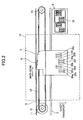
- FIG. 1 is a perspective view of an inkjet recording apparatus 1 according to an embodiment of the present invention.
- the inkjet recording apparatus 1 is a serial-type image forming apparatus that includes a carriage 5 and ink cartridges (main tank) 100.
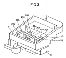
- FIG. 2 is a top plan view of a printing mechanism unit of the inkjet recording apparatus 1.
- the carriage 5 is slidably supported by a guide rod 3 and a guide rail 4 fixed between side plates (not shown) within a main body of the inkjet recording apparatus 1 ("apparatus main body").
- the carriage 5 can be slidably moved in a main scan direction indicated by a both-ends arrow.
- the carriage 5 may be configured to be guided along the guide rail 4 via a sub-guide roller 6 rotatably supported on a rear portion of the carriage 5.
- the carriage 5 is moved in the main-scan direction by a main scan mechanism which may include a drive motor 11 disposed at one end of a main scan path along the main-scan direction, a drive pulley 12 rotated by the drive motor 11, a driven pulley 13 disposed at the other end of the main scan path, and a timing belt (belt member) 14 extended across the drive pulley 12 and the driven pulley 13.
- the driven pulley 13 may be biased in a direction away from the drive pulley 12 by a tensioning spring (not shown).
- the drive pulley 12 and the driven pulley 13 are disposed such that their axes are parallel to a direction in which ink droplets are discharged, which is perpendicular to the sheet of the drawing of FIG.
- a part of the belt member 14 is fixed to a belt-fixing portion of the carriage 5 at a rear portion (which is at the top of FIG. 2 ).
- the belt member 14 is disposed on one side (i.e., rear) of the carriage 5.
- the carriage 5 carries recording heads 20a through 20j (any of which may be referred to as "the recording head 20").
- the recording heads 20a through 20j may include nozzles (not shown in FIGs. 2 and 3 ) via which ink droplets of the colors black (K), yellow (Y), magenta (M), and cyan (C) are discharged, and corresponding buffer tanks (sub-tanks) 22 (see FIG. 4 ).
- a pair of the recording heads 20a and 20b and a pair of the recording heads 20c and 20d are disposed in a staggered manner with respect to a sheet transport direction indicated by an arrow (which is downward in the sheet of FIG. 2 ).
- These pairs of the recording heads may be configured to discharge ink droplets of black.
- a group of the recording heads 20e through 20g and a group of the recording heads 20h through 20j are also disposed in a staggered manner in the sheet transport direction.
- the recording heads 4e and 4h may be configured to discharge ink droplets of cyan.
- the recording heads 20f and 20i may be configured to discharge ink droplets of magenta.
- the recording heads 20g and 20j may be configured to discharge ink droplets of yellow.
- a sheet 10 is transported in the sheet transport direction, which is a sub-scan direction perpendicular to the main scan direction, by a sheet-transport mechanism (not shown) in an intermittent manner.
- a maintain/recover mechanism 8 is disposed at one end of a main scan area corresponding to the width of the sheet 10.
- the maintain/recover mechanism 8 may include a cap 30 for capping a nozzle surface of the recording head 20, and a wiper member configured to wipe the nozzle surface.
- the ink cartridges (main tank) 100 are detachably mounted outside the main scan area as illustrated in FIG. 1 . It is noted that in FIG.
- the carriage 5 is positioned above the maintain/recover mechanism 8, i.e., at the right-hand end of the main-scan direction, as also illustrated in FIG. 3 .
- the carriage 5 is positioned within the main-scan area.
- the ink cartridges 100 contain the various colors of ink supplied to the recording head 20.
- the recording head 20 is driven in accordance with an image information signal in order to discharge the various colors of ink droplets onto the sheet 10 while the carriage 5 is moved in the main scan direction and the sheet 10 is intermittently moved in the sub-scan direction, so that a desired image can be formed on the sheet 10.
- the ink supply system includes the recording head 20, a supply tube 24, a pump 25, and the ink cartridge 100.
- the recording head 20 includes a nozzle portion 21 configured to discharge an ink droplet, and a buffer tank (sub-tank) portion 22 configured to supply ink to the nozzle portion 21.
- the ink cartridge 100 (liquid container) is a replaceable main tank that contains ink supplied to the recording head 20. The ink in the ink cartridge 100 is supplied to the buffer tank 22 via the supply tube 24.
- the ink cartridge 100 includes a cartridge case 101 in which a double-bag 104 (liquid containing bag) is housed.
- the double-bag 104 includes an ink bag 102 (inner bag) in which ink 300 (liquid) is contained, and an air bag 103 (outer bag) that contains the ink bag 102.
- a gas such as air
- the air bag 103 inflates and thereby applies pressure to the ink bag 102, thus causing the ink 300 in the ink bag 102 to be supplied outside the ink cartridge 100.
- air may be introduced into the air bag 103 using the pump 25 in order to supply the ink 300 to the recording head 20.
- the supply tube 24 is detachably connected to the ink bag 102 via a hollow needle 400, and the pump 25 is detachably connected to the air bag 103 via an air-joint portion 500.
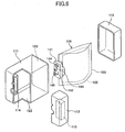
- FIG. 5 is a perspective view of the ink cartridge 100.
- FIG. 6 is an exploded perspective view of the ink cartridge 100.
- the ink cartridge 100 includes the cartridge case 101.
- the cartridge case 101 houses the double-bag 104, which includes the ink bag 102 containing ink and the air bag 103 that contains the ink bag 102.
- the air bag 103 is configured to be supplied with gas, such as air, so as to inflate and thereby apply pressure to the ink bag 102 in order to cause the ink to be supplied out of the ink cartridge 100.
- the ink bag 102 and the air bag 103 are fixedly attached to a spout 141 (joint member) which may be made of polyethylene or other resin material; by thermal fusing and the like, with the ink bag 102 located inside the air bag 103.
- the spout 141 has an ink supply opening 142 for supplying ink to the sub-tank 22, an ink inlet 143 for supplying ink to the ink bag 102, and an air inlet 144 for introducing air into the air bag 103.
- the ink supply opening 142 is internally fitted with a rubber seal 145.
- the hollow needle 400 at the end of the supply tube 24 of the ink supply system as described above pierces the rubber seal 145, thus providing fluid communication between the ink bag 102 and the apparatus main body. Even if the ink cartridge 100 is detached from the inkjet recording apparatus 1 with some ink remaining in the ink cartridge 100, the ink does not flow out of the ink cartridge 100 because of the resilience of the rubber seal 145 which closes the opening formed in the rubber seal 145 where the hollow needle 400 had pierced.
- the ink inlet 143 may be hermetically sealed by thermal fusing and the like.
- the ink bag 102 may be first evacuated by suctioning air out of it via the ink inlet 143, with the ink bag 102 compressed between a pair of flat boards and the like so as to keep the ink bag 102 flattened. In this way, entry of air into the ink in the ink bag 102 may be minimized.
- the air inlet 143 is in communication with the air bag 103 and is configured to introduce pressurized air from the apparatus main body into the air bag 103 so as to apply pressure to the ink bag 102 in a compressing direction during a print operation, for example.
- the cartridge case 101 includes a hollow body 111 configured to house the double-bag 104, a front cover 112 configured to cover a front opening portion 122 of the hollow body 111, and a rear cover 113 configured to cover a rear opening portion 123 of the hollow body 111.
- the front cover 112 and the rear cover 113 may be fixed to the hollow body 111 by various methods, such as by using screws, snap-fitting, fusing, or bonding, individually or in combination.
- the front opening portion 122 of the hollow body 111 is large enough that the double-bag 104 after use can be pulled out of the hollow body 111 via the front opening portion 122.
- the rear opening portion 123 is large enough that the double-bag 104 filled with ink can be inserted into the hollow body 111 via the rear opening portion 123.
- the hollow body 111, the front cover 112, and the rear cover 113 may be made by injection molding of resin material, such as polystyrene or ABS (acrylonitrile butadiene styrene) resin. From the viewpoint of recycling of material, it may be desirable to make the three components from the same material. Preferably, however, the hollow body 111 alone may be made of a high-strength resin because the hollow body 111 may be subject to the greatest load upon pressure application to the ink bag 102.
- resin material such as polystyrene or ABS (acrylonitrile butadiene styrene) resin.
- the hollow body 111 alone may be made of a high-strength resin because the hollow body 111 may be subject to the greatest load upon pressure application to the ink bag 102.
- the first spout fixing portion 114 is disposed on an inner surface of the hollow body 111 on the front opening 122 side.
- the first spout fixing portion 114 is configured such that the spout 141 of the double-bag 104 can be fixedly fitted in the first spout fixing portion 114.
- a second spout fixing portion 115 is disposed on an inner surface of the front cover 112.
- the second spout fixing portion 115 is also configured such that the spout 141 of the double-bag 104 can be fixedly fitted in the second spout fixing portion 115.
- openings 116 and 117 are formed in a front surface of the cartridge case 101 at locations corresponding to the supply opening 142 and the air inlet 143, as illustrated in FIG. 5 . These openings 116 and 117 allow access when connecting the hollow needle 400 and an air-joint portion 500 from the apparatus main body to the supply opening 142 and the air inlet 144, respectively.
- the double-bag 104 filled with ink is inserted into the hollow body 111 via the rear opening portion 123, and the spout 141 of the double-bag 104 is fitted in the first spout fixing portion 114 of the hollow body 111.
- the spout 141 of the double-bag 104 is also fixed by the second spout fixing portion 115 of the front cover 112 by attaching the front cover 112 to the front opening portion 122. Thereafter, the rear cover 113 is attached to the rear opening portion 123. In this way, the double-bag 104 containing deaerated ink can be housed within the cartridge case 101.
- the front cover 112 When disassembling the ink cartridge 100 after use, the front cover 112 is detached from the front opening portion 122 of the hollow body 111, and then the double-bag 104 is pulled out via the front opening portion 122.
- the double-bag 104 can be pulled out of the ink cartridge 100 for refill, for example, without having to detach the rear cover 113 from the hollow body 111.
- the portion of the cartridge case 101 to which the highest pressure may be applied i.e., the hollow body 111 is formed as an integral member and not as an assembly of two or more components.
- the hollow body 111 can withstand a high pressure.
- the rear opening portion 123 can be exposed, thus providing an access opening via which the double-bag 104 (liquid containing bag) filled with deaerated liquid can be inserted into the cartridge case 101.
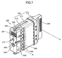
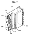
- FIG. 7 is a perspective view of an ink cartridge 200 according to Embodiment 2, as seen from its front end.
- FIG. 8 is also a perspective view of the ink cartridge 200 as seen from its rear end.
- the ink cartridge 200 includes a cartridge case 201 in which a double-bag 204 (liquid containing bag; see FIG. 9 ) is housed.
- the double-bag 204 includes an ink (inner) bag 202 that contains ink, and an air (outer) bag 203 within which the ink bag 202 is contained.
- the air bag 203 is configured to be supplied with gas so as to apply pressure to the ink bag 202 within and thereby cause the ink in the ink bag 202 to be supplied outside the ink cartridge 200.
- the ink bag 202 and the air bag 203 may be fixed to a spout 241 by thermal welding.
- the spout 241 is a coupling member made of a resin material, such as polyethylene.
- the spout 241 has an ink supply opening 242 for supplying ink to the apparatus main body, an ink inlet 243 for filling the ink bag 202 with ink, and an air inlet 244 for introducing air (gas) into the air bag 203.
- the ink supply opening 242 is internally fitted with a rubber seal 245 that is pierced by the hollow needle 400 from the apparatus main body when the ink cartridge 200 is attached to the apparatus main body, so as to allow fluid communication between the ink bag 202 and the apparatus main body.
- the resilience of the rubber seal 245 closes an opening formed in it where the rubber seal 245 is pierced by the hollow needle 400, so that the ink contained in the ink bag 202 does not flow out of the ink cartridge 200 even if the ink cartridge 200 is detached from the apparatus with some ink remaining in the ink cartridge 200.
- the ink inlet 243 is in communication with the ink bag 202. After the ink bag 202 is filled with ink via the ink inlet 243, the ink inlet 243 may be hermetically sealed by thermal fusing and the like. When filling the ink bag 202 with ink, the ink bag 202 may be first evacuated by suctioning air via the ink inlet 243 with the ink bag 202 compressed between a pair of flat boards and the like so as to keep the ink bag 202 flattened. In this way, entry of air into the ink in the ink bag 202 can be minimized.
- the air inlet 243 is in communication with the air bag 203 and is configured to introduce pressurized air from the apparatus main body into the air bag 203 so as to apply pressure to the ink bag 202 in a compressing direction during a print operation, for example.
- the cartridge case 201 includes a hollow body 211, a front cover 212 configured to cover a front opening portion 222 of the hollow body 211, and a rear cover 213 configured to cover a rear opening portion 223 of the hollow body 211.
- the front cover 212 may have a projecting portion 251, while the hollow body 211 may have a concave portion 252 shaped such that the projecting portion 251 of the front cover 212 can be fitted within the concave portion 252.
- the front cover 212 can be attached to the hollow body 211 using screws through openings 253 and 254, while ensuring their correct relative positions by the fitting of the projecting portion 251 in the concave portion 252.
- the front cover 212 and the rear cover 213 may be fixed to the hollow body 211 by various other methods, such as by using screws, snap-fitting, fusing, or bonding, individually or in combination.
- the hollow body 211 has the front opening portion 222 that is large enough that the double bag 204 after use can be pulled out via the front opening portion 222.
- the hollow body 211 also has the rear opening portion 223 that is large enough that the double bag 204 filled with ink can be installed via the rear opening portion 223.
- the hollow body 211, the front cover 212, and the rear cover 213 may be made by injection molding of resin material, such as polystyrene or ABS (acrylonitrile butadiene styrene) resin. From the viewpoint of recycling of material, it may be desirable to make the three components from the same material. Preferably, however, the hollow body 211 alone may be made of a high-strength resin because the hollow body 211 may be subject to the greatest load upon pressure application to the ink bag 202.
- resin material such as polystyrene or ABS (acrylonitrile butadiene styrene) resin.
- the hollow body 211 alone may be made of a high-strength resin because the hollow body 211 may be subject to the greatest load upon pressure application to the ink bag 202.
- the aforementioned first spout fixing portion 214 is disposed on an inner surface of the hollow body 211 at its front end.
- the first spout fixing portion 214 is configured such that the spout 241 of the double-bag 204 can be fixedly fitted in the first spout fixing portion 214.
- a second spout fixing portion 215 is disposed on an inner surface of the front cover 212.
- the second spout fixing portion 215 is positioned and configured such that, when the front cover 212 is attached to the hollow body 211, the spout 241 of the double-bag 204 can be fixed between the first and the second spout fixing portions 214 and 215.
- openings 216 and 217 are formed in the cartridge case 201 at locations corresponding to the supply opening 242 and the air inlet 243, respectively, as illustrated in FIG. 7 . These openings 216 and 217 allow access when connecting the hollow needle 400 and the air-joint portion 500 from the apparatus main body to the supply opening 242 and the air inlet 244, respectively.
- the cartridge case 201 which is formed by the hollow body 211, the front cover 212, and the rear cover 213 may have angled portions at the front and rear ends, as illustrated in FIG. 15 , for example, which is a cross section taken along line A-A' of FIG. 7 .
- front-side portions 255 and rearside portions 256 of the cartridge case 201 may be angled such that the width of the cartridge case 201 gradually decrease towards the front and rear of the cartridge case 201 in conformity with the cross-sectional outer shape of the double-bag 204.
- buttressing ribs 258 are formed, as illustrated in FIG. 7 .
- buttressing ribs 257 are formed, as illustrated in FIG. 8 . These buttressing ribs 257 and 258 are configured to make it difficult for the hollow body 211 or the front cover 212 to deform when pressure is applied to the ink bag 202.
- the internal wall surfaces of the cartridge case 201 may be smoothly formed so as to prevent the double-bag 204 from being scratched in case the cartridge case 201 is accidentally dropped, for example.
- an ID chip 261 may be fixed by thermal welding or a double-sided adhesive tape.
- a color-identifying rib 262 having a color corresponding to the color of the contained ink may be integrally formed. The location of the color-identifying rib 262 may be varied depending on the color of the ink so that the attachment of the ink cartridge 200 having the wrong color to the apparatus main body can be prevented.
- the front cover 212 may also include a positioning rib 263 extending from a front cover main body 212a of the front cover 212 toward the rear cover 213, parallel to the direction in which the cartridge case 201 is attached to the apparatus main body, as illustrated in FIGs. 7 through 9 and particularly FIG. 11 .
- the positioning rib 263 makes it possible to attach the cartridge case 201 to the apparatus main body with increased positional accuracy.
- the areas of the cartridge case 201 around the buttressing ribs 257 and 258 have a relatively small amount of deformation upon application of pressure to the ink bag 202.
- the double-bag 204 filled with ink is inserted into the cartridge case 201 via the rear opening portion 223 of the hollow body 211, and then the spout 241 of the double-bag 204 is attached to the first spout fixing portion 214 of the hollow body 211.
- the spout 241 of the double-bag 204 is fixed to the second spout fixing portion 215 of the front cover 212.
- the rear cover 213 is attached to the opening portion 223 of the hollow body 211. In this way, the double-bag 204 containing deaerated ink can be housed within the cartridge case 201.
- the front cover 212 When disassembling the ink cartridge 200 after use, the front cover 212 is detached from the front opening portion 222, and then the double-bag 204 is removed via the opening portion 222.
- the double-bag 204 can be refilled, for example, without detaching the rear cover 213 from the hollow body 211.
Landscapes
- Engineering & Computer Science (AREA)
- Manufacturing & Machinery (AREA)
- Ink Jet (AREA)
Claims (13)
- Cartouche d'encre (100, 200) pour utiliser dans un appareil à jet d'encre (1), comprenant :un boîtier (101, 201) ; etun sac contenant de l'encre (104, 204) contenu dans le boîtier (101, 201), le sac contenant de l'encre ayant une partie d'ouverture d'alimentation (141, 241) et étant configuré pour contenir de l'encre alimentée vers l'appareil à jet d'encre (1) via l'ouverture d'alimentation,dans laquelle le boîtier (101, 201) inclutun corps creux formé d'un seul bloc (111, 211) comportant une partie d'ouverture avant (122, 222), une partie d'ouverture arrière (123, 223), et une partie de fixation d'ouverture d'alimentation (114, 214) à laquelle la partie d'ouverture d'alimentation (141, 241) du sac contenant de l'encre (104, 204) est fixée de manière fixe ;un couvercle avant (112, 212) configuré pour couvrir la partie d'ouverture avant (122, 212) du corps creux ; etun couvercle arrière (113, 213) configuré pour couvrir la partie d'ouverture arrière (123, 223) du corps creux (111, 211),dans lequel la partie d'ouverture avant (122, 222) est suffisamment grande pour que le sac contenant de l'encre (104, 204) après utilisation puisse être tiré hors du corps creux (111, 211) via la partie d'ouverture avant,la partie d'ouverture arrière (123, 223) est suffisamment grande pour que le sac contenant de l'encre (104, 204) rempli avec de l'encre puisse être inséré dans le corps creux (111, 211) via la partie d'ouverture arrière, etla partie de fixation d'ouverture d'alimentation (114, 214) est disposée sur une extrémité avant du corps creux et agencée de telle manière que la partie d'ouverture d'alimentation (141, 241) du sac contenant de l'encre (104, 204) peut être attachée sur la partie de fixation d'ouverture d'alternativement (114, 214) quand la partie d'ouverture avant (122, 222) n'est pas couverte par le couvercle avant (112, 212).
- Cartouche d'encre (200) selon la revendication 1, dans laquelle le boîtier (201) est formé pour se conformer à la forme du sac contenant de l'encre (204).
- Cartouche d'encre (200) selon la revendication 1 ou 2, dans laquelle le boîtier (201) inclut des parties inclinées ayant des largeurs décroissant progressivement vers une extrémité avant et une extrémité arrière du boîtier en conformité avec le sac contenant de l'encre (204) ayant des largeurs décroissantes vers une extrémité avant et une extrémité arrière.
- Cartouche d'encre (200) selon la revendication 3, dans laquelle une nervure d'étai (258) est disposée sur la partie inclinée du boîtier (201).
- Cartouche d'encre (200) selon l'une quelconque des revendications 1 à 4, comprenant en outre une puce d'identification (261) disposée sur une surface avant du boîtier (201).
- Cartouche d'encre (200) selon l'une quelconque des revendications 1 à 5, dans laquelle le couvercle avant (212) inclut un élément de positionnement (263) configuré pour définir une position de la cartouche d'encre (200) par rapport à l'appareil à jet d'encre (1) quand la cartouche d'encre (200) est fixée sur l'appareil à jet d'encre.
- Cartouche d'encre (200) selon la revendication 6, dans laquelle l'élément de positionnement (263) est en forme de ruban et s'étend depuis le couvercle avant (212) vers le couvercle arrière (213) parallèle à une direction dans laquelle la cartouche d'encre (200) est fixée sur l'appareil à jet d'encre (1).
- Cartouche d'encre (100, 200) selon l'une quelconque des revendications 1 à 7, dans laquelle le sac contenant de l'encre (104, 204) inclut
un sac intérieur (102, 202) configuré pour contenir l'encre (300) ; et
un sac extérieur (103, 202) dans lequel le sac intérieur (102, 202) est logé et configuré pour appliquer une pression sur le sac intérieur lors de l'introduction d'un gaz dans le sac extérieur de façon à faire s'écouler l'encre hors du sac intérieur,
dans lequel le sac extérieur (103, 203) entre en contact avec la surface de paroi intérieure du boîtier (101, 201) lors de l'introduction du gaz dans le sac extérieur. - Cartouche d'encre (100, 200) selon la revendication 8, dans laquelle le sac extérieur (103, 203) a un volume plus grand qu'un volume d'une partie du boîtier (101, 201) dans lequel le sac extérieur est logé.
- Cartouche d'encre (100, 200) selon l'une quelconque des revendications précédentes, dans laquelle la partie d'ouverture avant (122, 222) est configurée de telle manière qu'elle expose une partie d'une partie avant du corps creux (111, 211) laissant une partie du bord avant du corps creux restante ;
la partie de fixation d'ouverture d'alimentation est agencée sur la partie restante du bord avant du corps creux ; et
la partie d'ouverture arrière (123, 223) ouvre la partie arrière entière du corps creux (111, 211). - Procédé d'assemblage de la cartouche d'encre (100, 200) selon l'une quelconque des revendications précédentes, comprenant les étapes consistant à :insérer le sac contenant de l'encre (104, 204) rempli avec l'encre dans le corps creux (111, 211) via la partie d'ouverture arrière (123, 223) ;fixer la partie d'ouverture d'alimentation (141, 241) du sac contenant de l'encre (104, 204) sur la partie de fixation d'ouverture d'alternativement (114, 214) du corps creux (111, 211) ;fixer le couvercle avant (112, 212) sur la partie d'ouverture avant (122, 222) du corps creux (111, 211) ; etfixer le couvercle arrière (113, 213) sur la partie d'ouverture arrière (123, 223) du corps creux (111, 211).
- Procédé de désassemblage de la cartouche d'encre (100, 200) selon l'une quelconque des revendications 1 à 10, comprenant les étapes consistant à :enlever le couvercle avant (112, 212) de la partie d'ouverture avant (122, 222) du corps creux (111, 211) ; etpousser le sac contenant de l'encre (104, 204) hors du corps creux (111, 211) via la partie d'ouverture avant (122, 222).
- Appareil à jet d'encre (1) comprenant la cartouche d'encre (100, 200) selon l'une quelconque des revendications 1 à 10, dans lequel la cartouche d'encre (100, 200) est fixée de manière amovible sur un corps principal de l'appareil à jet d'encre.
Applications Claiming Priority (1)
| Application Number | Priority Date | Filing Date | Title |
|---|---|---|---|
| JP2009205193A JP5316326B2 (ja) | 2009-09-04 | 2009-09-04 | 液体収容容器、液体収容容器の組立て方法、液体収容容器の分解方法及び画像形成装置 |
Publications (2)
| Publication Number | Publication Date |
|---|---|
| EP2292431A1 EP2292431A1 (fr) | 2011-03-09 |
| EP2292431B1 true EP2292431B1 (fr) | 2013-06-05 |
Family
ID=43014263
Family Applications (1)
| Application Number | Title | Priority Date | Filing Date |
|---|---|---|---|
| EP10251527.7A Not-in-force EP2292431B1 (fr) | 2009-09-04 | 2010-08-27 | Récipient pour liquides, procédés de montage et de démontage du récipient et appareil de formation d'images |
Country Status (4)
| Country | Link |
|---|---|
| US (1) | US8454143B2 (fr) |
| EP (1) | EP2292431B1 (fr) |
| JP (1) | JP5316326B2 (fr) |
| CN (1) | CN102009528B (fr) |
Families Citing this family (27)
| Publication number | Priority date | Publication date | Assignee | Title |
|---|---|---|---|---|
| JP5440264B2 (ja) * | 2010-03-05 | 2014-03-12 | 株式会社リコー | インクカートリッジおよび画像形成装置 |
| US8651643B2 (en) | 2010-10-22 | 2014-02-18 | Hewlett-Packard Development Company, L.P. | Fluid cartridge |
| JP5824945B2 (ja) * | 2011-07-29 | 2015-12-02 | ブラザー工業株式会社 | インクカートリッジ及びインクジェットプリンタ |
| JP5948848B2 (ja) * | 2011-12-16 | 2016-07-06 | セイコーエプソン株式会社 | 液体収容体 |
| JP5842616B2 (ja) | 2012-01-05 | 2016-01-13 | 株式会社リコー | 液体カートリッジ、画像形成装置 |
| US9440755B2 (en) * | 2012-01-13 | 2016-09-13 | Seiko Epson Corporation | Liquid container and liquid consumption apparatus |
| US8657143B2 (en) * | 2012-04-12 | 2014-02-25 | Honda Motor Co., Ltd. | Small engine fuel tank systems and mounting methods |
| MY166230A (en) * | 2012-08-10 | 2018-06-22 | Seiko Epson Corp | Liquid container, liquid consuming apparatus, liquid supply system and liquid container unit |
| JP6085922B2 (ja) | 2012-09-13 | 2017-03-01 | 株式会社リコー | 液体カートリッジ及び画像形成装置 |
| US8919921B2 (en) | 2012-11-15 | 2014-12-30 | Ricoh Company, Ltd. | Image forming apparatus |
| US8608299B1 (en) | 2012-12-21 | 2013-12-17 | Jetbest Corporation | Ink cartridge with replaceable ink bag |
| JP6142581B2 (ja) | 2013-03-07 | 2017-06-07 | 株式会社リコー | 画像形成装置 |
| JP5887295B2 (ja) * | 2013-03-28 | 2016-03-16 | 京セラドキュメントソリューションズ株式会社 | インクコンテナ及びインクジェット式画像形成装置 |
| JP6476551B2 (ja) * | 2013-05-15 | 2019-03-06 | セイコーエプソン株式会社 | カートリッジ、および、印刷材供給システム |
| JP6303349B2 (ja) | 2013-09-17 | 2018-04-04 | 株式会社リコー | 液体カートリッジ及び画像形成装置 |
| JP2015058542A (ja) * | 2013-09-17 | 2015-03-30 | セイコーエプソン株式会社 | 液体収容体 |
| JP2015080872A (ja) * | 2013-10-22 | 2015-04-27 | セイコーエプソン株式会社 | 液体収容容器の再生方法、および液体収容容器 |
| JP6269234B2 (ja) * | 2014-03-26 | 2018-01-31 | セイコーエプソン株式会社 | 液体容器、アダプター、ならびに液体噴射装置 |
| JP6393541B2 (ja) * | 2014-07-17 | 2018-09-19 | 株式会社ミマキエンジニアリング | 収納容器、接続器具および接続方法 |
| US9902167B2 (en) * | 2015-06-29 | 2018-02-27 | Dover Europe Sarl | Maintenance aid device of a hydraulic circuit |
| US10300702B2 (en) | 2015-07-22 | 2019-05-28 | Hewlett-Packard Development Company, L.P. | Printing fluid container |
| US10112404B2 (en) | 2016-11-03 | 2018-10-30 | Funai Electric Co., Ltd. | Fluidic ejection cartridge with molded ceramic body |
| JP7119683B2 (ja) * | 2018-07-17 | 2022-08-17 | セイコーエプソン株式会社 | 液体噴射装置 |
| CN111268191B (zh) * | 2020-04-08 | 2021-10-08 | 义乌市昕闵日用品有限公司 | 一种异形袋加压灌装机 |
| JP7665377B2 (ja) * | 2021-03-30 | 2025-04-21 | キヤノン株式会社 | 液体収容容器 |
| JP7753819B2 (ja) * | 2021-11-15 | 2025-10-15 | セイコーエプソン株式会社 | インクパック、インクパックの製造方法 |
| JP2023151581A (ja) | 2022-03-31 | 2023-10-16 | ブラザー工業株式会社 | 液体収容カートリッジ及びプリンタ |
Family Cites Families (22)
| Publication number | Priority date | Publication date | Assignee | Title |
|---|---|---|---|---|
| JPS6171444U (fr) * | 1984-10-18 | 1986-05-15 | ||
| US6170937B1 (en) * | 1997-01-21 | 2001-01-09 | Hewlett-Packard Company | Ink container refurbishment method |
| US5860363A (en) * | 1997-01-21 | 1999-01-19 | Hewlett-Packard Company | Ink jet cartridge with separately replaceable ink reservoir |
| US6010210A (en) * | 1997-06-04 | 2000-01-04 | Hewlett-Packard Company | Ink container having a multiple function chassis |
| WO1999008876A1 (fr) * | 1997-08-18 | 1999-02-25 | Hewlett-Packard Company | Systeme d'impression a moyen de controle de l'accumulation d'air permettant de realiser une tete d'impression semi-permanente sans purge d'air |
| KR100404637B1 (ko) * | 1997-08-28 | 2003-11-07 | 세이코 엡슨 가부시키가이샤 | 폐잉크 흡수기능을 갖는 잉크카트리지 |
| JP4210034B2 (ja) | 1998-03-04 | 2009-01-14 | ヒューレット・パッカード・カンパニー | インク容器を一新するシステム |
| US6243115B1 (en) * | 2000-03-09 | 2001-06-05 | Lexmark International, Inc. | Pressurized ink supply and delivery system for an ink jet printer |
| JP4032628B2 (ja) * | 2000-10-17 | 2008-01-16 | セイコーエプソン株式会社 | インクバッグセット、それを装着するようにしたプリンタ及びプリンタシステム並びにそれを用いた制御方法 |
| JP3667284B2 (ja) * | 2001-02-09 | 2005-07-06 | キヤノン株式会社 | 液体収納容器および記録装置 |
| US6609789B1 (en) * | 2002-03-11 | 2003-08-26 | Banctec, Inc. | Ink cartridge |
| US20040012660A1 (en) * | 2002-07-18 | 2004-01-22 | Eastman Kodak Company | Ink cartridge having connectable-disconnectable housing and ink supply bag |
| JP3919734B2 (ja) * | 2002-12-06 | 2007-05-30 | 株式会社リコー | インクカートリッジ及びその筺体、画像形成装置 |
| JP2004306505A (ja) * | 2003-04-09 | 2004-11-04 | Brother Ind Ltd | インクパッケージ |
| JP2004314558A (ja) * | 2003-04-21 | 2004-11-11 | Ricoh Co Ltd | 液体収容袋の液体充填方法及び装置 |
| JP4556580B2 (ja) | 2004-09-14 | 2010-10-06 | セイコーエプソン株式会社 | 液体収容体の収納容器及び液体噴射装置 |
| WO2006070981A1 (fr) | 2004-12-29 | 2006-07-06 | D5 Co., Ltd. | Reservoir d’encre pour systeme d’impression a jet d’encre |
| JP2007083497A (ja) * | 2005-09-21 | 2007-04-05 | Seiko Epson Corp | インクパックトレイ |
| JP4770369B2 (ja) * | 2005-09-29 | 2011-09-14 | ブラザー工業株式会社 | インクカートリッジ及びそのインクカートリッジに内包されるフレーム |
| US8002380B2 (en) * | 2007-12-28 | 2011-08-23 | Brother Kogyo Kabushiki Kaisha | Cartridge-information detecting device |
| JP5141348B2 (ja) * | 2008-04-14 | 2013-02-13 | 株式会社リコー | 記録液収納容器及び画像形成装置 |
| JP5176967B2 (ja) * | 2009-01-06 | 2013-04-03 | 株式会社リコー | インクカートリッジ及び画像形成装置 |
-
2009
- 2009-09-04 JP JP2009205193A patent/JP5316326B2/ja not_active Expired - Fee Related
-
2010
- 2010-08-27 US US12/870,222 patent/US8454143B2/en not_active Expired - Fee Related
- 2010-08-27 EP EP10251527.7A patent/EP2292431B1/fr not_active Not-in-force
- 2010-09-03 CN CN2010102774780A patent/CN102009528B/zh not_active Expired - Fee Related
Also Published As
| Publication number | Publication date |
|---|---|
| US8454143B2 (en) | 2013-06-04 |
| JP5316326B2 (ja) | 2013-10-16 |
| US20110057997A1 (en) | 2011-03-10 |
| CN102009528A (zh) | 2011-04-13 |
| JP2011051321A (ja) | 2011-03-17 |
| EP2292431A1 (fr) | 2011-03-09 |
| CN102009528B (zh) | 2013-08-21 |
Similar Documents
| Publication | Publication Date | Title |
|---|---|---|
| EP2292431B1 (fr) | Récipient pour liquides, procédés de montage et de démontage du récipient et appareil de formation d'images | |
| EP1403064B1 (fr) | Réservoir d'encre, tête d'enregistrement et dispositif d'impression comprenant ledit réservoir | |
| JP5176967B2 (ja) | インクカートリッジ及び画像形成装置 | |
| US6113228A (en) | Ink container for compact supply station | |
| US9592675B2 (en) | Liquid fill container | |
| US5534899A (en) | Replaceable ink tank | |
| US6003985A (en) | Ink jet recording apparatus | |
| US8454136B2 (en) | Ink cartridge and image forming apparatus employing the ink cartridge | |
| CA2565475C (fr) | Reservoir d'encre, tete d'impression et appareil d'impression a jet d'encre | |
| US11491796B2 (en) | Inkjet printing apparatus and ink tank | |
| US9346278B2 (en) | Packaging tray and packaging body | |
| JP5353565B2 (ja) | 液体収容容器及び画像形成装置 | |
| JP5440264B2 (ja) | インクカートリッジおよび画像形成装置 | |
| JP5304110B2 (ja) | 液体カートリッジユニット | |
| WO2007066789A1 (fr) | Dispositif d’impression a jet d’encre et son reservoir d’encre | |
| US6286934B1 (en) | Ink jet printer including detachable print cartridge | |
| CN101687420B (zh) | 流体喷射装置及其制造方法 | |
| JP2005319587A (ja) | 液体収能容器、インクジェット記録装置、及び画像形成装置 | |
| EP4512625A1 (fr) | Appareil d'éjection de liquide | |
| US20250042161A1 (en) | Printing apparatus and liquid storage tank | |
| KR100832590B1 (ko) | 잉크 탱크, 인쇄 헤드 및 잉크젯 인쇄 장치 | |
| HK1060546A (en) | Ink container, recording head and recording device using same | |
| JP2010274470A (ja) | 自己封止弁及びそれを備えた液体噴射装置並びに電子機器、液体充填方法 |
Legal Events
| Date | Code | Title | Description |
|---|---|---|---|
| PUAI | Public reference made under article 153(3) epc to a published international application that has entered the european phase |
Free format text: ORIGINAL CODE: 0009012 |
|
| 17P | Request for examination filed |
Effective date: 20100914 |
|
| AK | Designated contracting states |
Kind code of ref document: A1 Designated state(s): AL AT BE BG CH CY CZ DE DK EE ES FI FR GB GR HR HU IE IS IT LI LT LU LV MC MK MT NL NO PL PT RO SE SI SK SM TR |
|
| AX | Request for extension of the european patent |
Extension state: BA ME RS |
|
| GRAP | Despatch of communication of intention to grant a patent |
Free format text: ORIGINAL CODE: EPIDOSNIGR1 |
|
| RIC1 | Information provided on ipc code assigned before grant |
Ipc: B41J 2/175 20060101AFI20121212BHEP |
|
| GRAS | Grant fee paid |
Free format text: ORIGINAL CODE: EPIDOSNIGR3 |
|
| GRAA | (expected) grant |
Free format text: ORIGINAL CODE: 0009210 |
|
| AK | Designated contracting states |
Kind code of ref document: B1 Designated state(s): AL AT BE BG CH CY CZ DE DK EE ES FI FR GB GR HR HU IE IS IT LI LT LU LV MC MK MT NL NO PL PT RO SE SI SK SM TR |
|
| REG | Reference to a national code |
Ref country code: GB Ref legal event code: FG4D |
|
| REG | Reference to a national code |
Ref country code: CH Ref legal event code: EP |
|
| REG | Reference to a national code |
Ref country code: AT Ref legal event code: REF Ref document number: 615411 Country of ref document: AT Kind code of ref document: T Effective date: 20130615 |
|
| REG | Reference to a national code |
Ref country code: IE Ref legal event code: FG4D |
|
| REG | Reference to a national code |
Ref country code: DE Ref legal event code: R096 Ref document number: 602010007551 Country of ref document: DE Effective date: 20130801 |
|
| REG | Reference to a national code |
Ref country code: AT Ref legal event code: MK05 Ref document number: 615411 Country of ref document: AT Kind code of ref document: T Effective date: 20130605 |
|
| PG25 | Lapsed in a contracting state [announced via postgrant information from national office to epo] |
Ref country code: ES Free format text: LAPSE BECAUSE OF FAILURE TO SUBMIT A TRANSLATION OF THE DESCRIPTION OR TO PAY THE FEE WITHIN THE PRESCRIBED TIME-LIMIT Effective date: 20130916 Ref country code: AT Free format text: LAPSE BECAUSE OF FAILURE TO SUBMIT A TRANSLATION OF THE DESCRIPTION OR TO PAY THE FEE WITHIN THE PRESCRIBED TIME-LIMIT Effective date: 20130605 Ref country code: LT Free format text: LAPSE BECAUSE OF FAILURE TO SUBMIT A TRANSLATION OF THE DESCRIPTION OR TO PAY THE FEE WITHIN THE PRESCRIBED TIME-LIMIT Effective date: 20130605 Ref country code: SI Free format text: LAPSE BECAUSE OF FAILURE TO SUBMIT A TRANSLATION OF THE DESCRIPTION OR TO PAY THE FEE WITHIN THE PRESCRIBED TIME-LIMIT Effective date: 20130605 Ref country code: NO Free format text: LAPSE BECAUSE OF FAILURE TO SUBMIT A TRANSLATION OF THE DESCRIPTION OR TO PAY THE FEE WITHIN THE PRESCRIBED TIME-LIMIT Effective date: 20130905 Ref country code: GR Free format text: LAPSE BECAUSE OF FAILURE TO SUBMIT A TRANSLATION OF THE DESCRIPTION OR TO PAY THE FEE WITHIN THE PRESCRIBED TIME-LIMIT Effective date: 20130906 Ref country code: SE Free format text: LAPSE BECAUSE OF FAILURE TO SUBMIT A TRANSLATION OF THE DESCRIPTION OR TO PAY THE FEE WITHIN THE PRESCRIBED TIME-LIMIT Effective date: 20130605 Ref country code: FI Free format text: LAPSE BECAUSE OF FAILURE TO SUBMIT A TRANSLATION OF THE DESCRIPTION OR TO PAY THE FEE WITHIN THE PRESCRIBED TIME-LIMIT Effective date: 20130605 |
|
| REG | Reference to a national code |
Ref country code: NL Ref legal event code: VDEP Effective date: 20130605 |
|
| REG | Reference to a national code |
Ref country code: LT Ref legal event code: MG4D |
|
| PG25 | Lapsed in a contracting state [announced via postgrant information from national office to epo] |
Ref country code: BG Free format text: LAPSE BECAUSE OF FAILURE TO SUBMIT A TRANSLATION OF THE DESCRIPTION OR TO PAY THE FEE WITHIN THE PRESCRIBED TIME-LIMIT Effective date: 20130905 Ref country code: HR Free format text: LAPSE BECAUSE OF FAILURE TO SUBMIT A TRANSLATION OF THE DESCRIPTION OR TO PAY THE FEE WITHIN THE PRESCRIBED TIME-LIMIT Effective date: 20130605 |
|
| PG25 | Lapsed in a contracting state [announced via postgrant information from national office to epo] |
Ref country code: LV Free format text: LAPSE BECAUSE OF FAILURE TO SUBMIT A TRANSLATION OF THE DESCRIPTION OR TO PAY THE FEE WITHIN THE PRESCRIBED TIME-LIMIT Effective date: 20130605 |
|
| PG25 | Lapsed in a contracting state [announced via postgrant information from national office to epo] |
Ref country code: BE Free format text: LAPSE BECAUSE OF FAILURE TO SUBMIT A TRANSLATION OF THE DESCRIPTION OR TO PAY THE FEE WITHIN THE PRESCRIBED TIME-LIMIT Effective date: 20130605 Ref country code: SK Free format text: LAPSE BECAUSE OF FAILURE TO SUBMIT A TRANSLATION OF THE DESCRIPTION OR TO PAY THE FEE WITHIN THE PRESCRIBED TIME-LIMIT Effective date: 20130605 Ref country code: EE Free format text: LAPSE BECAUSE OF FAILURE TO SUBMIT A TRANSLATION OF THE DESCRIPTION OR TO PAY THE FEE WITHIN THE PRESCRIBED TIME-LIMIT Effective date: 20130605 Ref country code: CZ Free format text: LAPSE BECAUSE OF FAILURE TO SUBMIT A TRANSLATION OF THE DESCRIPTION OR TO PAY THE FEE WITHIN THE PRESCRIBED TIME-LIMIT Effective date: 20130605 Ref country code: PT Free format text: LAPSE BECAUSE OF FAILURE TO SUBMIT A TRANSLATION OF THE DESCRIPTION OR TO PAY THE FEE WITHIN THE PRESCRIBED TIME-LIMIT Effective date: 20131007 Ref country code: IS Free format text: LAPSE BECAUSE OF FAILURE TO SUBMIT A TRANSLATION OF THE DESCRIPTION OR TO PAY THE FEE WITHIN THE PRESCRIBED TIME-LIMIT Effective date: 20131005 |
|
| PG25 | Lapsed in a contracting state [announced via postgrant information from national office to epo] |
Ref country code: NL Free format text: LAPSE BECAUSE OF FAILURE TO SUBMIT A TRANSLATION OF THE DESCRIPTION OR TO PAY THE FEE WITHIN THE PRESCRIBED TIME-LIMIT Effective date: 20130605 Ref country code: RO Free format text: LAPSE BECAUSE OF FAILURE TO SUBMIT A TRANSLATION OF THE DESCRIPTION OR TO PAY THE FEE WITHIN THE PRESCRIBED TIME-LIMIT Effective date: 20130605 Ref country code: PL Free format text: LAPSE BECAUSE OF FAILURE TO SUBMIT A TRANSLATION OF THE DESCRIPTION OR TO PAY THE FEE WITHIN THE PRESCRIBED TIME-LIMIT Effective date: 20130605 |
|
| PLBE | No opposition filed within time limit |
Free format text: ORIGINAL CODE: 0009261 |
|
| STAA | Information on the status of an ep patent application or granted ep patent |
Free format text: STATUS: NO OPPOSITION FILED WITHIN TIME LIMIT |
|
| PG25 | Lapsed in a contracting state [announced via postgrant information from national office to epo] |
Ref country code: MC Free format text: LAPSE BECAUSE OF FAILURE TO SUBMIT A TRANSLATION OF THE DESCRIPTION OR TO PAY THE FEE WITHIN THE PRESCRIBED TIME-LIMIT Effective date: 20130605 Ref country code: DK Free format text: LAPSE BECAUSE OF FAILURE TO SUBMIT A TRANSLATION OF THE DESCRIPTION OR TO PAY THE FEE WITHIN THE PRESCRIBED TIME-LIMIT Effective date: 20130605 |
|
| 26N | No opposition filed |
Effective date: 20140306 |
|
| REG | Reference to a national code |
Ref country code: IE Ref legal event code: MM4A |
|
| PG25 | Lapsed in a contracting state [announced via postgrant information from national office to epo] |
Ref country code: IT Free format text: LAPSE BECAUSE OF FAILURE TO SUBMIT A TRANSLATION OF THE DESCRIPTION OR TO PAY THE FEE WITHIN THE PRESCRIBED TIME-LIMIT Effective date: 20130605 |
|
| REG | Reference to a national code |
Ref country code: DE Ref legal event code: R097 Ref document number: 602010007551 Country of ref document: DE Effective date: 20140306 |
|
| PG25 | Lapsed in a contracting state [announced via postgrant information from national office to epo] |
Ref country code: IE Free format text: LAPSE BECAUSE OF NON-PAYMENT OF DUE FEES Effective date: 20130827 |
|
| REG | Reference to a national code |
Ref country code: CH Ref legal event code: PL |
|
| PG25 | Lapsed in a contracting state [announced via postgrant information from national office to epo] |
Ref country code: CH Free format text: LAPSE BECAUSE OF NON-PAYMENT OF DUE FEES Effective date: 20140831 Ref country code: LI Free format text: LAPSE BECAUSE OF NON-PAYMENT OF DUE FEES Effective date: 20140831 |
|
| PG25 | Lapsed in a contracting state [announced via postgrant information from national office to epo] |
Ref country code: SM Free format text: LAPSE BECAUSE OF FAILURE TO SUBMIT A TRANSLATION OF THE DESCRIPTION OR TO PAY THE FEE WITHIN THE PRESCRIBED TIME-LIMIT Effective date: 20130605 |
|
| PG25 | Lapsed in a contracting state [announced via postgrant information from national office to epo] |
Ref country code: TR Free format text: LAPSE BECAUSE OF FAILURE TO SUBMIT A TRANSLATION OF THE DESCRIPTION OR TO PAY THE FEE WITHIN THE PRESCRIBED TIME-LIMIT Effective date: 20130605 Ref country code: CY Free format text: LAPSE BECAUSE OF FAILURE TO SUBMIT A TRANSLATION OF THE DESCRIPTION OR TO PAY THE FEE WITHIN THE PRESCRIBED TIME-LIMIT Effective date: 20130605 Ref country code: MT Free format text: LAPSE BECAUSE OF FAILURE TO SUBMIT A TRANSLATION OF THE DESCRIPTION OR TO PAY THE FEE WITHIN THE PRESCRIBED TIME-LIMIT Effective date: 20130605 |
|
| PG25 | Lapsed in a contracting state [announced via postgrant information from national office to epo] |
Ref country code: LU Free format text: LAPSE BECAUSE OF NON-PAYMENT OF DUE FEES Effective date: 20130827 Ref country code: HU Free format text: LAPSE BECAUSE OF FAILURE TO SUBMIT A TRANSLATION OF THE DESCRIPTION OR TO PAY THE FEE WITHIN THE PRESCRIBED TIME-LIMIT; INVALID AB INITIO Effective date: 20100827 Ref country code: MK Free format text: LAPSE BECAUSE OF FAILURE TO SUBMIT A TRANSLATION OF THE DESCRIPTION OR TO PAY THE FEE WITHIN THE PRESCRIBED TIME-LIMIT Effective date: 20130605 |
|
| REG | Reference to a national code |
Ref country code: FR Ref legal event code: PLFP Year of fee payment: 7 |
|
| REG | Reference to a national code |
Ref country code: FR Ref legal event code: PLFP Year of fee payment: 8 |
|
| REG | Reference to a national code |
Ref country code: FR Ref legal event code: PLFP Year of fee payment: 9 |
|
| PG25 | Lapsed in a contracting state [announced via postgrant information from national office to epo] |
Ref country code: AL Free format text: LAPSE BECAUSE OF FAILURE TO SUBMIT A TRANSLATION OF THE DESCRIPTION OR TO PAY THE FEE WITHIN THE PRESCRIBED TIME-LIMIT Effective date: 20130605 |
|
| PGFP | Annual fee paid to national office [announced via postgrant information from national office to epo] |
Ref country code: DE Payment date: 20200819 Year of fee payment: 11 Ref country code: GB Payment date: 20200826 Year of fee payment: 11 Ref country code: FR Payment date: 20200821 Year of fee payment: 11 |
|
| REG | Reference to a national code |
Ref country code: DE Ref legal event code: R119 Ref document number: 602010007551 Country of ref document: DE |
|
| GBPC | Gb: european patent ceased through non-payment of renewal fee |
Effective date: 20210827 |
|
| PG25 | Lapsed in a contracting state [announced via postgrant information from national office to epo] |
Ref country code: GB Free format text: LAPSE BECAUSE OF NON-PAYMENT OF DUE FEES Effective date: 20210827 Ref country code: FR Free format text: LAPSE BECAUSE OF NON-PAYMENT OF DUE FEES Effective date: 20210831 Ref country code: DE Free format text: LAPSE BECAUSE OF NON-PAYMENT OF DUE FEES Effective date: 20220301 |