EP2292469A1 - Dispositif de fixation doté d'un étrier - Google Patents
Dispositif de fixation doté d'un étrier Download PDFInfo
- Publication number
- EP2292469A1 EP2292469A1 EP10009112A EP10009112A EP2292469A1 EP 2292469 A1 EP2292469 A1 EP 2292469A1 EP 10009112 A EP10009112 A EP 10009112A EP 10009112 A EP10009112 A EP 10009112A EP 2292469 A1 EP2292469 A1 EP 2292469A1
- Authority
- EP
- European Patent Office
- Prior art keywords
- clamping
- clamping nut
- fastening device
- actuating
- tie rod
- Prior art date
- Legal status (The legal status is an assumption and is not a legal conclusion. Google has not performed a legal analysis and makes no representation as to the accuracy of the status listed.)
- Granted
Links
Images



Classifications
-
- B—PERFORMING OPERATIONS; TRANSPORTING
- B60—VEHICLES IN GENERAL
- B60R—VEHICLES, VEHICLE FITTINGS, OR VEHICLE PARTS, NOT OTHERWISE PROVIDED FOR
- B60R9/00—Supplementary fittings on vehicle exterior for carrying loads, e.g. luggage, sports gear or the like
- B60R9/06—Supplementary fittings on vehicle exterior for carrying loads, e.g. luggage, sports gear or the like at vehicle front or rear
-
- F—MECHANICAL ENGINEERING; LIGHTING; HEATING; WEAPONS; BLASTING
- F16—ENGINEERING ELEMENTS AND UNITS; GENERAL MEASURES FOR PRODUCING AND MAINTAINING EFFECTIVE FUNCTIONING OF MACHINES OR INSTALLATIONS; THERMAL INSULATION IN GENERAL
- F16B—DEVICES FOR FASTENING OR SECURING CONSTRUCTIONAL ELEMENTS OR MACHINE PARTS TOGETHER, e.g. NAILS, BOLTS, CIRCLIPS, CLAMPS, CLIPS OR WEDGES; JOINTS OR JOINTING
- F16B37/00—Nuts or like thread-engaging members
- F16B37/08—Quickly-detachable or mountable nuts, e.g. consisting of two or more parts; Nuts movable along the bolt after tilting the nut
- F16B37/0807—Nuts engaged from the end of the bolt, e.g. axially slidable nuts
- F16B37/0864—Nuts engaged from the end of the bolt, e.g. axially slidable nuts with the threaded portions of the nut engaging the thread of the bolt by pressing or rotating an external retaining member such as a cap, a nut, a ring or a sleeve
Definitions
- the invention relates to a fastening device for a motor vehicle carrier, in particular a bicycle carrier, with a screwed onto a threaded portion of a threaded body clamping nut of a clamping nut assembly, wherein the clamping nut is lubbetätigbar means of a rotatably connected to the clamping nut or connected handle body to the clamping nut along the threaded portion axially to adjust.
- the invention further relates to a motor vehicle carrier equipped with such a fastening device.
- the clamping nut can develop sufficient clamping forces, usually the pitch of the thread is relatively low. This, however, complicates the operation since an operator has to perform a large number of revolutions in order to move the clamping nut along the threaded section, that is to say to loosen or close or clamp the fastening device.
- the clamping nut mounted at least two relatively movable Tensioner parts, which are by means of an actuating body between an engagement position in the internal thread of the Spannmutter compiler engaged with the threaded portion of the threaded body, and a release position in which the internal threads of the Spannmuttermaschine are out of engagement with the threaded portion of the threaded body and the clamping nut along the threaded portion is displaceable, are adjustable.
- the operation of the clamping nut assembly is very simple and fast.
- the actuating body - it can also be provided a plurality of actuator body - the clamping nut can be adjusted to its release position, so that an operator can move the clamping nut without a rotary actuator along the threaded portion.
- the operating body moves the clamping nut parts into engagement with the threaded portion, so that the clamping nut is in engagement with the threaded portion and can be screwed.
- At least one of the tension nut members may also be fixedly connected to or integral with the actuator body provided that the actuator body is transverse to the threaded portion, i. transverse to the screw axis, is movable and thus can be brought out of engagement with the threaded portion.
- a wedge gear is present.
- the actuating body has a corresponding oblique surface or a plurality of corresponding inclined surfaces.
- An inclined surface is not absolutely necessary. It can also be a frictional entrainment.
- a spring arrangement which acts on the Spannmuttermaschine in the release position.
- This spring arrangement is expediently provided between the actuating body and the clamping nut parts.
- the tensioning nut parts due to a forced operation and / or by corresponding actuation of the actuating body e.g. a rotary actuator and / or sliding operation
- the threaded portion cooperates with the clamping nut such that it acts on the Spannmutterile in the direction of the release position, if the operating body does not oppose.
- the spring or spring arrangement is advantageous, but not necessary.
- the Spannmuttermaschine can also be formed by sections which are correspondingly movable projecting from a base body of the clamping nut so that they can be brought into engagement and out of engagement with the threaded portion.
- the Spannmuttermaschine can thus be part of a generally advantageous one-piece clamping nut, but be movably mounted with respect to the base body.
- the actuator body forms part of an actuator body housing, i. that the clamping nut arrangement is arranged in the housing of the actuating body.
- This housing may be permanently closed, for example welded, which may constitute a theft protection, in particular in connection with the lock described below.
- the actuating body has expediently a receptacle for at least partial, preferably total absorption of the clamping nut and / or arranged between the actuating body and the clamping nut spring.
- This recording can for example be equipped with the aforementioned inclined surfaces.
- the actuator body has a cup-shaped recess in which one or more springs are received, this recess widens outwardly with inclined surfaces, which at the same time form the inclined surfaces for the wedge gear. At these inclined surfaces, the clamping nut, or their Spannmutter compiler are slidably mounted.
- the actuating body expediently has a support surface facing away from the clamping nut for supporting on an abutment such that the actuating body loads the clamping nut into the engagement position when it is supported on the support surface.
- the abutment is for example of a Distance element or provided by another to exciting component of the fastening device.
- the support surface protrudes in front of the handle body.
- indirect support is also possible, for example by having an object, e.g. a spacer sleeve or the like, engages in the handle body and there acts on the support surface of the actuating body.
- the threaded portion penetrates expediently the actuating body. But it is also conceivable that the threaded portion extends adjacent to the actuator body.
- the actuator body is suitably rotatably connected to the clamping nut or connectable. This is readily realizable, for example, by a toothing, by one or more grooves, in which corresponding projections engage.
- the actuator body and the handle body are in fact advantageous rotatably connected or connectable.
- connection or “connectable” is to be understood that the respective rotational strength may be permanent or temporary, for example, depending on an axial position of the respective components (actuator body to clamping nut, nut to handle body, actuator body to handle body).
- actuator body to clamping nut, nut to handle body, actuator body to handle body.
- a non-rotatable combination handle body - actuator body - clamping nut for example, realized by the fact that the handle body rotatably connected to the actuator body and the actuator body rotatably connected to the clamping nut or connected. Again, it should be emphasized that a direct torsional strength between the one hand the hand body and the other part of the clamping nut is readily feasible.
- a lock is advantageously provided which is adjustable between a rotational drive of the clamping nut realizing the open position and a closed position in which the handle body relative to the clamping nut is freely rotatable.
- the lock is suitably rotatably connected to the handle body.
- the lock has an advantageous effect on the operating body on the clamping nut and is in the closed position out of engagement with the actuating body. In the open position, it is in engagement with the actuating body. Now, if the actuating body in turn rotatably connected or connectable with the clamping nut, a rotational grip between the handle body and clamping nut is realized in this way.
- the fastening device in particular the clamping nut or the clamping nut arrangement as a whole.
- a particular on the clamping nut assembly e.g. provided on a handle body, arranged lock, which cooperates with the threaded portion.
- the lock could, for example, have a closing projection, which engages in the closed position of the lock in the threaded portion and obstructs an adjustment of the clamping nut arrangement, in particular the clamping nut or one of the Spannmutter compiler, in the sense of locking.
- the actuating body is expediently movably mounted on the handle body, for example, axially movable.
- a mobility transverse to the axis or along a curved trajectory is conceivable.
- the axis is defined, for example, by the threaded portion. If now the actuating body has at least a part of the clamping nut or realized a Spannmutterteil, the operating body can be disengaged or engaged with the threaded portion.
- the fastening device advantageously has a clamp for attachment to a carrier body in particular of the motor vehicle carrier, with a clamping body for clamping a first annular body exciting end and a second annular body exciting end of an annular body of the clamp towards each other, on, wherein the clamping body on opposite outer sides the two annular body-exciting supports, such that an intended for engagement or penetration of the support body inner cross section of the annular body is changed in an adjustment of the clamping body from a release position into a clamping position in the sense of bracing the fastening device to the support body.
- the clamping body is movably mounted along a directed to a central region of the inner cross section of the clamp, in particular linear, clamping movement path from the release position to the clamping position, and that between the clamping body and at least one of the annular body exciting to a Spannkraftbeetzschlagung is provided transversely to the clamping movement path at least one inclined surface whose distance increases from the clamping movement path in the direction of the central region.
- a self-contained invention thus relates to a fastening device for a motor vehicle carrier, in particular a bicycle carrier, with a clamp for attachment to a carrier body in particular of the motor vehicle carrier, with a clamping body for bracing a first annular body exciting end and a second annular body exciting one Ring body of the clamp towards each other, with the clamping body on opposite outer sides of the supporting both annular body-exciting, such that an intended for engagement or penetration of the support body inner cross section of the annular body is changed in an adjustment of the clamping body from a release position to a clamping position in the sense of bracing the fastening device to the support body, wherein provided in the fastening device, in that the clamping body is movably mounted from the release position into the clamping position along a, in particular linear, clamping movement path directed towards a central region of the inner cross section of the clamp, and at least one clamping force acting transversely to the clamping movement path between the clamping body and at least one of the annular body Inclined
- the clamp has an optimal introduction of force. Unlike conventional clamps, in which the clamping force is introduced laterally next to the support body, such as a pipe, bracket or the like, in the clamp, so that, for example, between a threaded rod which serves as a clamping body of the usual clamp, and the central region of the inner cross section the clamp or the clamp center is a lever. Thus, therefore, no optimal introduction of force or force transmission between the support body and the clamp or attached to the clamp other components of the fastening device in the prior art is possible.
- the power flow is optimal because, for example, the threaded rod, which serves as a clamping body, so to speak protrudes from the central region of the clamp or from the center of the clamp.
- the clamping body for example, the threaded rod, projects directly from the carrier body and is not arranged laterally next to it, as is the case in the prior art.
- the at least one inclined surface is for example a wedge surface.
- a wedge gear or a bevel gear is provided between the clamping body and the ring body.
- inclined surfaces are provided on opposite sides of the annular body-exciting and / or on mutually facing sides of the clamping body.
- the inclined surfaces are flat surfaces or flat surfaces. But it is also possible that each other angled or curved, in particular cylindrical, inclined surfaces are provided.
- the at least one inclined surface may also be stepped and / or toothed.
- the inclined surface runs, for example, tangentially away from the respective annular body-exciting.
- the inclined surface (s) has / have a non-self-locking inclination.
- the respective inclined surface may have an inclination in the range of 20 to 60 degrees, preferably about 30 degrees, obliquely to the clamping path.
- the clamping body could in principle be supported on its surroundings, for example any component of the motor vehicle carrier.
- a self-supporting and supporting construction is preferred.
- the fastening device preferably has a tie rod, which is fastened or fastened to a tie rod holder of the ring body tensile strength.
- the clamping body is supported on the tie rod, at least in its clamping position directly or indirectly.
- a direct support could, for example, be created by the fact that there is a thread on the tie rod, which meshes with a thread of the clamping body.
- an actuating element could be provided on the tie rod, which in turn is supported on the tie rod, for example, a clamping nut, in particular the clamping nut arrangement according to the invention.
- the at least one tie rod holder of the annular body and a Switzerlandwiderlagerelement the tie rod at least one tie rod receptacle and at least one tensile projection for engagement in the tie rod receptacle, wherein expediently between the at least one tensile projection and the at least one Tie rod recording in the release position of the clamping body a game is present, which is reduced in the clamping position, and / or advantageously wherein the at least one inclined surface in the region of the at least one tie rod receptacle is arranged and subjected to force in the clamping position in the direction of at least one Ceivorsprungs is.
- tie rod next to the ring body exciting on the ring body tensile strength supported For example, the ring body-exciting between two tie rod holders, which are provided on the ring body, could be arranged.
- At least one, preferably both, of the annular body-exciting has at least one support part of the tie rod holder.
- the tie rod is supported on both annular body exciting or is held by two annular body exciting tension.
- the at least one tie rod holder of the annular body and a Switzerlandwiderlagerelement of Switzerlandankers preferably comprise a Switzerlandankerfact and at least one tensile projection which engages in the tie rod receiving.
- the tensile projection is provided, for example, on the tie rod, the tie rod receptacle on the annular body. But it is also the reverse arrangement (recording on the ring body, projection on the tie rod, projection on the ring body) possible.
- a clearance is present at least in the release position of the clamping body, which is reduced in the clamping position or no longer exists.
- the respective annular body exciting can move in the direction of the movement path.
- an elastic property of the annular body which preferably consists of plastic, may be sufficient to allow the closing movement or clamping movement of the respective annular body exciting.
- the annular body exciting advantageously comprise at least one part of the tie rod holder. Preference is given to facing each other open tie rod receptacles, engage in the oppositely arranged on the Buchwiderlagerelement of the tie rod Wervorsprünge. For example, a kind of plate or a compression is provided at the end of the tie rod as Ceiwiderlagerelement.
- the tie rod is suitably held against rotation on the ring body. This facilitates, for example, the screwing of an actuator on the tie rod, which preferably has a threaded portion.
- the tie rod expediently penetrates the clamping body. As a result, an optimal introduction of force and support of the clamping body on the tie rod is possible.
- the clamping body is guided on the tie rod and / or a longitudinal axis of the tie rod defines the clamping movement path. It is therefore preferred if the clamping body is guided on the tie rod.
- An advantageous measure provides that a longitudinal axis of the particular rod-shaped or rectilinear tie rod defines the clamping movement.
- the tie rod does not necessarily have to have a straight course, but also can be curved.
- the tie rod is at least partially rigid, in particular rod-shaped, and / or at least partially flexible.
- the tie rod is expediently at least partially rigid.
- the tie rod is rod-shaped at one or more of its sections.
- the tie rod could be made of spring steel.
- the tie rod has a threaded portion in particular arranged on a threaded portion on which a clamping nut or the clamping nut assembly is screwed for adjusting the clamping body on which the clamping body is supported directly or indirectly.
- an inner circumference and / or an outer circumference of the annular body is substantially annular.
- the geometry of the clamp is preferably adapted to the respective geometry of the carrier body.
- the carrier body has, for example, a rectangular outer contour
- the inner circumference or the inner contour of the annular body is expediently likewise adapted in a rectangular manner.
- the carrier body is cylindrical, designed for example as a cylindrical tube
- the inner circumference of the annular body is expediently essentially annular.
- the outer circumference of the annular body may advantageously be substantially annular.
- the clamping body has a sleeve-like or ring-like or part-ring-like shape.
- the clamping body is expediently sleeve-like, i. designed as a sleeve, or ring-like.
- the clamping body can also be partial ring-like.
- the clamping body can also be multi-part or that several clamping bodies can be provided.
- the clamping body does not act directly on the annular body, but via a ausgestaltetes example as a wedge element transmission element.
- the annular body is in one piece or consists of at least two interconnected ring segments and / or at least one particular connected by the tie rod with the clamp clamp for staple-like holding an object, in particular a bicycle having.
- the ring body so not only a one-piece design, but also a multi-part is possible.
- the ring body may consist of two or more interconnected or connectable ring segments.
- the fastening device expediently has a clamp for the clamp-like holding of an article, for example a bicycle or another article to be conveyed with, in particular, the motor vehicle carrier.
- the clamp is held, for example, by the tie rod, which is connected to the clamp.
- one and the same clamping nut on the one hand serves to clamp the clamp on the carrier body and on the other hand to adjust the clamp in its holding the object holding position.
- a single operation namely a twisting of the clamping nut in order to close or brace the clamp and the clamp.
- the meshing in particular with a threaded portion of the tie rod clamping nut is provided for adjusting the clamping body in its clamping position.
- a clamping nut with which the clamping body is adjustable in its clamping position in particular the clamping nut of the clamping nut assembly according to the invention.
- the ring body presses, so to speak, the clamping body in its release position. It is preferred here that due to the non-self-locking tendency of the at least one inclined surface no self-locking between on the one hand the ring body and on the other hand, the clamping body occurs.
- a spacer sleeve or another spacer can be provided between the clamping body and the clamping nut.
- the spacer sleeve is expediently provided between the clamp and the clamp.
- the tie rod expediently has a threaded portion.
- the tie rod is designed as a threaded rod or has such.
- the clamping nut combs expediently with a threaded portion of the tie rod.
- Particularly preferred is the use of the invention in motor vehicle carriers, in particular bicycle carriers.
- the motor vehicle carrier can be fastened or fastened, for example, at the rear or on the roof of a motor vehicle.
- the motor vehicle carrier for example, a rear carrier, which is in particular drawer-like extendable from a motor vehicle rear.
- An attachment of the motor vehicle carrier on a towing device, such as a ball coupling, is advantageous.
- the motor vehicle carrier has a corresponding fastening device for attachment to the trailer coupling.
- the fastening device is expediently designed for fastening an object to the motor vehicle carrier, but can also serve for fixing components of the motor vehicle carrier.
- a component movably mounted on a base of the load carrier e.g. to attach a support for a load, a support platform or the like.
- a support can be slidably and / or pivotably mounted on a base of the motor vehicle carrier and fixed by means of the fastening device according to the invention fixed, for example in a position of use and / or a non-use position.
- a motor vehicle carrier 10 can be fastened (schematically) to the rear of a motor vehicle 11, for example to its trailer coupling, not shown, by means of a holding device 12.
- the holding device 12 is located on a substantially U-shaped carrier base 13, on which a pivoting frame 14 of the motor vehicle Carrier 10 is pivotally mounted.
- the pivoting frame 14 is pivotable about a pivot axis, which runs substantially parallel to a light carrier 15 of the motor vehicle carrier 10.
- the light carrier 15 carries lights 16 and a license plate carrier 17.
- the pivoting frame 14 also has a U-shaped configuration.
- the carrier base 13 and the pivoting frame 14 serve to carry and convey articles on the motor vehicle carrier 10.
- bicycle carrier troughs 19 for mounting bicycles on the motor vehicle carrier 10 are provided on the carrier arms 18. These bicycles can be fastened with flexible straps 20.
- the staple position K is shown, which serves for grasping or stapling the object to be held, for example, a frame tube of a bicycle.
- a schematically illustrated spring 34 may be arranged in a conventional manner, which urges the two clip legs 32 in their open position.
- a spacer body 35 for example a spacer sleeve 36 is provided.
- a fastening device which is assigned to the more distant from the motor vehicle 11 bike carrier channels 19, one would provide a correspondingly longer spacer sleeve 36.
- the respective fastening device 30 can be fastened to the bracket 21 by means of a clamp 40, which in this respect forms a carrier body 23 for the fastening device 30.
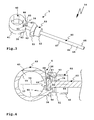
- the clamp 40 surrounds the at least in the region of the clamp 40 substantially cylindrical, for example formed by a tubular body support body 23 by means of an annular body 41, the annular body-exciting 42 are tensioned in a clamping position S by a clamping body 50 in the sense of bracing the support body 23 ,
- a tie rod 60 is further provided, the tensile strength is attached to the ring body 41 by means of a tie rod holder 46.
- Pull projections 62 which are formed for example by a square 63, are accommodated in tie rod receptacles 47 of the annular body 41.
- the tie rod receptacles 47 are at the ring body exciting 42 provided and facing each other open.
- the tie rod receptacles 47 are U-shaped. Due to the angular configuration of the tie rod receptacles 47, the tensile resistance element 61, which, as stated, is polygonal or polygonal on its outer circumference, is received in a rotationally fixed manner.
- the tie rod receptacles 47 have projections 48 arranged between the inner cross section 43 and the tie rod 60, so that the tie rod 60 does not come into contact with the inner cross section 43 in the detachment position.
- the tie rod 60 is radially with a tie rod 64 from the clamp 40 from.
- the tie rod 64 penetrates an opening provided on overlap projections 49.
- the overlapping projections 49 are components of the tie rod receptacles 47 and engage over the tensile resistance element 61 with respect to the inner cross section 43 from radially outside.
- the tie rod 64 penetrates the clamping body 50, the spacer body 35, the clamp 31 close to the clamp bearing 33, expediently arranged between the clamp legs 32 spring 34 and finally a clamping nut assembly 70 which is screwed from the free end 65 of the tie rod 64 forth on this.
- the clamping nut arrangement 70 serves for clamping the fastening device 30.
- the clamping nut arrangement 70 serves to close the clamp 31 or to apply it to its clamping position K and also to clamp the clamp 40, i. for applying the clamping body 50 in its clamping position S.
- the clamping nut arrangement 70 comprises a multipart clamping nut 71, which in the present case has two clamping nut parts 72.
- the clamping nut 71 can be rotatably operated with a handle body 80 to one at least in the region of the free end 65 of the tie rod 60 provided threaded portion 66 to be screwed. In the region of the threaded portion 66, the tie rod 60 forms a threaded body 67.
- the clamping nut 71 By screwing onto the threaded portion 66, the clamping nut 71 first loads the clip 31 or its clip leg 32 into the clip position K and also via the clip 31 and the spacer 35 - it can also be provided more spacers - the clamping body 50 in its clamping position S.
- the spacer body 35 is supported on a support surface 51 of the clamping body 50.
- the support surface 51 is annular and extends around an engagement projection 52, which engages in an inner space of the spacer sleeve 36.
- the engagement projection 52 is circular cylindrical on its outer side to match a circular cylindrical inner circumference of the spacer sleeve 36, so that it sits with little or no play on the clamping body 50.
- the clamping body 50 On its side opposite the engagement projection 52, the clamping body 50 has a clamping surface part 53.
- the clamping surface part 53 is truncated pyramid.
- the tie rod 60 penetrates a passage opening 54 of a wall 55 between the engaging projection 52 and the clamping surface portion 53.
- An inner periphery of the passage opening 54 fits the outer periphery of the tie rod 64, so that the clamping body 50 is guided on the tie rod 60.
- the clamping nut assembly 70 when the clamping nut assembly 70 is screwed onto the threaded portion 66, it acts on the clamping body 50 at least indirectly, this being guided along a clamping movement path 37 defined by a central axis of the tie rod 64.
- the clamping body 50 is adjusted in the direction of the clamp 40, wherein inclined surfaces 56 at the inside of the clamping surface portion 53 slide on inclined surfaces 38 along the annular body-exciting 42, so that they are adjusted towards each other.
- the inner cross section 43 decreases, as a result of which the clamp 40 is braced on the carrier body 23.
- the inclined surfaces 38 are provided on the tie rod receptacles 47 facing away from the sides of the annular body-exciting 42.
- the inclined surfaces 38 extend tangentially away from the ends of the annular body-exciting end 42 facing the tie rod 60 in the direction of the substantially circular outer circumference of the annular body 41.
- the inclined surfaces 38 and 56 are present planar surfaces.
- the inclined surfaces 38, 56 are substantially flat against each other, so that the clamping body 50 so to speak slips on the clamp 40 and the ring body 41.
- the clamping body 50 acts on the annular body-exciting 42 to each other, i. in the direction of the tension movement path 37.
- a distance of the inclined surfaces 38, 56 from the tensioning trajectory 37 increases in the direction of a central region 39 of the inner cross section 43.
- a symmetrical arrangement is made in the embodiment, i. the tensioning motion path 37 forms, so to speak, a central axis or mirror axis with respect to the inclined surfaces 38, 56 arranged on both sides thereof. This allows a uniform tensioning of the two annular body tensioning ends 42 towards the tensioning movement path 37.
- the tension projections 62 and the tie rod holder 46 receiving them are provided with a play 68, so that movement of the ring body tensioning faces 42 towards the tensioning movement path 37 is possible. Nevertheless, the pull projections 62 always engage sufficiently deep in the tie rod receptacles 47, so that the tie rod 60 is always held securely on the ring body 41. To also contributes that the annular body-exciting 42 engage in an interior 57 with the inclined surfaces 56 of the clamping body 50.
- the inclined surfaces 56 are also in the region of the Wernerelements 61 on the outside of the annular body-exciting 42, so that the tie rod receptacles 47 are subjected to force in the direction of the tie rod 60.
- the tie rod 60 is thus so particularly safe and firmly held on the ring body 41.
- tie rod 60 which at the same time forms a mounting base for the other components of the fastening device 30, namely the bracket 31, projects radially from the carrier body 23. Side next to the carrier body 23 so no space is necessary.
- the handling of the clamping nut assembly 70 is particularly simple and is fast.
- the handle body 80 is designed knob-like and is conveniently in the hands of an operator.
- the handle body 80 forms a housing 81 for the clamping nut 71 and substantially for an actuating body 90, which is provided for actuating the Spannmuttermaschine 72 in the engaged position E.
- the handle body 80 could be designed in one piece, which in the illustration according to FIG FIGS. 5a, 5b the case is, or even in several parts. From a technical point of view It is advantageous if the interior space 82 is accessible through a mounting opening 83 which can be closed by a cover 84.
- the cover 84 can be fastened to the housing 81, for example, by means of screw bolts or rivets, not shown, through screw openings 85. Also possible would be a thread on the outer circumference of the lid 84, which is screwed into a thread on the inner circumference of the mounting hole 83.
- the cover 84 has a passage opening 86 for a support portion 91 of the actuator body 90.
- a support surface 92 is provided with which the actuator body 90 can be supported on an abutment 93, for example, the bracket 31.
- the support portion 91 is in Essentially cylindrical.
- the support surface 92 has a passage opening 94 for the tie rod 60, in particular its tie rod 64.
- the actuator body 90 projects with the free end of the support portion 91 in front of the lid 84 closed by the housing 81 of the handle body 80, so that the actuating body 90 on the Abutment 93 can be supported to be displaced into the interior 82 into it.
- the actuator body 90 is movably mounted with respect to the handle body 80.
- the handle body 80 is guided, for example, through the inner circumference of the passage opening 86, on which slides the cylindrical outer periphery of the support portion 91 along.
- the passage opening 86 is circular, corresponding to the outer periphery of the support portion 91, so that the actuating body 90 with respect to the passage opening 86 is rotatable.
- a rotation or a rotational drive for example, by a projection on the outer circumference of the support portion 91, which engages in a recess at the passage opening 86 (or vice versa), by a toothing between the two components or the like. It is useful, however, if the actuating body 90, while rotatably on the handle body 80, but axially along a defined by the tie rod 64 Verstellachse 69 movable.
- the tie rod 64 penetrates not only the actuator body 90 (passage opening 94), but also the handle body 80, namely at a tie rod passage opening 88 on a top wall 87 of the housing 81st
- a rotational drive between the handle body 80 and the actuator body 90 is realized by a sprocket 95 of the actuator body 90 and a lock 100 which is rotationally fixed with respect to the handle body 80.
- the lock 100 is shown only schematically and inserted, for example, in a passage opening or insertion opening 89 on the top wall 87.
- the ring gear 95 is located on one of the support surface 92 opposite side of the actuator body 90 and protrudes radially outward in front of the cylindrical outer periphery 96 of the support portion 91.
- the toothing of the ring gear 95 is rounded, i. between teeth 97 of the ring gear 95 are provided rounded portions.
- the lock 100 When the clamping nut assembly 70 is unlocked, the lock 100 is thus in its open position (FIG. FIG. 9a ), engages a driving contour, in this case a cylinder contour 101, of the lock 100 in one of the recesses between the teeth 97 a. As a result, a rotational drive between the lock 100, which in turn sits firmly in the handle body 80 and ultimately realized a rotational drive between the handle body 80 and the actuator body 90.
- a driving contour in this case a cylinder contour 101
- the rotational drive between the clamping nut 71 and the actuator body 90 is realized by a polygonal receptacle 99 in which the Spannmuttermaschine 72, which also have a polygonal contour on the outside, rotationally fixed, but axially adjustable with respect to the adjustment 69, are added.
- the two Spannmuttermaschine 72 are designed as wedge pieces.
- the Spannmuttermaschine 72 have on its threaded portion 66 facing the screw side 73 cylindrical recesses with internal threads 74, which are in the engaged position E into engagement with the threaded portion 66.
- an inclined surface 76 On one of the oblique surface side 75 opposite inclined surface side of a respective Spannmutterteils 72 is an inclined surface 76, with which the Spannmutterteil 72 slides on an inclined surface 98 of the actuator body 90 along.
- the inclined surfaces 98 are provided on a receptacle 99 of the actuating body 90, in which the two Spannmuttermaschine 72 are substantially received.
- a distance between the inclined surfaces 76, 98 of the adjustment axis 69 is smaller in the region of the support surface 92 than at a greater distance from the support surface 92.
- the inclined surfaces 76, 98 are So inclined to the support surface 92 towards obliquely.
- the inclined surfaces 76, 98 form components of a bevel gear or wedge gear 29 for adjusting the Spannmuttermaschine 72 in the engaged position E.
- the receptacle 99 also comprises a spring receptacle 27, in which a spring 25 of a spring assembly 26 is accommodated.
- the spring 25 is supported on the one hand on the actuating body 90 and on the other hand on the two Spannmutter matter 72, namely on a spring support side 77.
- the spring assembly 26 is supported on the bottom of the receptacle 99 from.
- the spring support side 77 extends between the respective screw side 73 and the inclined surface side 75 of a Spannmutterteils 72nd
- the Spannmuttermaschine 72 with its handle body support sides 78, ie the spring support sides 77 opposite sides, supported on the handle body 80, for example on the top wall 87 or disposed thereon support projections ( FIGS. 5a, 5b ).
- the spring assembly 26 acts on the Spannmuttermaschine 72 in the release position F ( FIG. 5a ).
- the clamping nut 71 can be adjusted by applying force in the direction of the abutment 93 in the engaged position E. For example, an operator presses on the top wall 87.
- the handle body 80 loads the tension nut parts 72 in the direction of the abutment 93 against the spring force of the spring arrangement 26.
- the tension nut parts 72 slide with their inclined surfaces 76 along the corresponding inclined surfaces 98 of the actuating body 90, so that the internal thread 74 in the direction of the adjustment axis 69, ie towards the threaded portion 66 toward, be relocated and finally engage in this.
- the clamping nut 71 can be screwed to the abutment 93 out. A loosening of the clamping nut 70 is thereby prevented that the clamping nut 71 presses the actuating body 90 in the direction of the abutment 93, but this can not escape due to the abutment 93 and applied via the wedge gear 29, the two Spannmuttermaschine 72 in the engagement position E with a force ,
Landscapes
- Engineering & Computer Science (AREA)
- Mechanical Engineering (AREA)
- General Engineering & Computer Science (AREA)
- Clamps And Clips (AREA)
Applications Claiming Priority (2)
| Application Number | Priority Date | Filing Date | Title |
|---|---|---|---|
| DE200910039820 DE102009039820A1 (de) | 2009-09-02 | 2009-09-02 | Befestigungseinrichtung mit einer Schelle |
| DE200910039822 DE102009039822A1 (de) | 2009-09-02 | 2009-09-02 | Befestigungseinrichtung mit einer Spannmutteranordnung |
Publications (2)
| Publication Number | Publication Date |
|---|---|
| EP2292469A1 true EP2292469A1 (fr) | 2011-03-09 |
| EP2292469B1 EP2292469B1 (fr) | 2016-03-30 |
Family
ID=43217001
Family Applications (1)
| Application Number | Title | Priority Date | Filing Date |
|---|---|---|---|
| EP10009112.3A Active EP2292469B1 (fr) | 2009-09-02 | 2010-09-02 | Dispositif de fixation doté d'un étrier |
Country Status (1)
| Country | Link |
|---|---|
| EP (1) | EP2292469B1 (fr) |
Cited By (1)
| Publication number | Priority date | Publication date | Assignee | Title |
|---|---|---|---|---|
| CN109373099A (zh) * | 2018-12-18 | 2019-02-22 | 沧州隆泰迪管道科技有限公司 | 四瓣卡箍式快开盲板以及使用方法 |
Citations (9)
| Publication number | Priority date | Publication date | Assignee | Title |
|---|---|---|---|---|
| FR1016817A (fr) * | 1950-04-28 | 1952-11-24 | Système de fixation réglable pour objets cylindriques | |
| US4930961A (en) * | 1988-12-23 | 1990-06-05 | Weis Charles W | Quick lock and release fastener |
| DE4037255A1 (de) * | 1990-11-23 | 1992-05-27 | Bayerische Motoren Werke Ag | Halterung eines reserverades an einer wandung eines kraftfahrzeugs |
| DE4304239A1 (de) * | 1993-02-12 | 1994-08-18 | Rixen & Kaul Gmbh | Befestigungsvorrichtung für Zubehör an Rohren und Stangen |
| WO2000066899A1 (fr) * | 1999-04-28 | 2000-11-09 | Oliveira Et Irmao S.A. | Ecrou a montage et demontage rapide |
| US20020001504A1 (en) * | 2000-01-10 | 2002-01-03 | Mccallion James P. | Threaded compression-enhanced fastening device for use with threaded rods |
| EP1233192A2 (fr) * | 2001-02-20 | 2002-08-21 | Wolfgang Dipl.-Ing. Rixen | Raccord pour tube à élément de connexion |
| WO2007015976A2 (fr) * | 2005-07-26 | 2007-02-08 | Alan Virdee | Mécanisme de couplage fileté comprenant une fonction d’introduction et de retrait |
| FR2902473A1 (fr) * | 2006-06-15 | 2007-12-21 | Peugeot Citroen Automobiles Sa | Dispositif formant ecrou a montage rapide |
-
2010
- 2010-09-02 EP EP10009112.3A patent/EP2292469B1/fr active Active
Patent Citations (9)
| Publication number | Priority date | Publication date | Assignee | Title |
|---|---|---|---|---|
| FR1016817A (fr) * | 1950-04-28 | 1952-11-24 | Système de fixation réglable pour objets cylindriques | |
| US4930961A (en) * | 1988-12-23 | 1990-06-05 | Weis Charles W | Quick lock and release fastener |
| DE4037255A1 (de) * | 1990-11-23 | 1992-05-27 | Bayerische Motoren Werke Ag | Halterung eines reserverades an einer wandung eines kraftfahrzeugs |
| DE4304239A1 (de) * | 1993-02-12 | 1994-08-18 | Rixen & Kaul Gmbh | Befestigungsvorrichtung für Zubehör an Rohren und Stangen |
| WO2000066899A1 (fr) * | 1999-04-28 | 2000-11-09 | Oliveira Et Irmao S.A. | Ecrou a montage et demontage rapide |
| US20020001504A1 (en) * | 2000-01-10 | 2002-01-03 | Mccallion James P. | Threaded compression-enhanced fastening device for use with threaded rods |
| EP1233192A2 (fr) * | 2001-02-20 | 2002-08-21 | Wolfgang Dipl.-Ing. Rixen | Raccord pour tube à élément de connexion |
| WO2007015976A2 (fr) * | 2005-07-26 | 2007-02-08 | Alan Virdee | Mécanisme de couplage fileté comprenant une fonction d’introduction et de retrait |
| FR2902473A1 (fr) * | 2006-06-15 | 2007-12-21 | Peugeot Citroen Automobiles Sa | Dispositif formant ecrou a montage rapide |
Cited By (1)
| Publication number | Priority date | Publication date | Assignee | Title |
|---|---|---|---|---|
| CN109373099A (zh) * | 2018-12-18 | 2019-02-22 | 沧州隆泰迪管道科技有限公司 | 四瓣卡箍式快开盲板以及使用方法 |
Also Published As
| Publication number | Publication date |
|---|---|
| EP2292469B1 (fr) | 2016-03-30 |
Similar Documents
| Publication | Publication Date | Title |
|---|---|---|
| EP2163358B1 (fr) | Poignée supplémentaire pour une machine-outil manuelle | |
| EP2292471B1 (fr) | Dispositif de fixation doté d'un étrier | |
| DE102009039822A1 (de) | Befestigungseinrichtung mit einer Spannmutteranordnung | |
| EP0754595B1 (fr) | Système variable de fixation rapide d?un coffre de toit sur les transverses d'une galerie de toit | |
| DE202019005604U1 (de) | Vorrichtung zum Verbinden zweier Gegenstände | |
| EP2271537A1 (fr) | Poussette repliable pour enfants et/ou poupées | |
| EP2766226A1 (fr) | Porte-charge de toit pour véhicule automobile | |
| EP2210709B1 (fr) | Pied de support pour visseuses | |
| DE102004059339A1 (de) | Ratschenspannvorrichtung zum Spannen von Gegenständen wie Gurten und Planen | |
| EP2292469B1 (fr) | Dispositif de fixation doté d'un étrier | |
| DE102005030054B4 (de) | Öffnungsvorrichtung | |
| DE202007008802U1 (de) | Verstellgriffmechanismus für Rollwagen, Stapelkarren u.dgl. | |
| WO2022002673A1 (fr) | Dispositif de tension pour tendre des chaînes, des courroies, des câbles ou des moyens en tension analogues | |
| DE3409988C2 (fr) | ||
| EP2345558B1 (fr) | Dispositif de serrage pour un support de véhicule automobile ou pour un attelage | |
| EP0015303B1 (fr) | Galerie pour véhicules | |
| EP2316673B1 (fr) | Dispositif de liaison pour un attelage ou un support de charge | |
| DE19715081A1 (de) | Radmutternschlüssel | |
| DE102011083358A1 (de) | Spannvorrichtung, insbesondere für einen Dachträger eines Kraftfahrzeugs | |
| DE202021003452U1 (de) | Spindelspanner | |
| DE202017103040U1 (de) | Trägeranordnung für ein Fahrzeug | |
| DE4324803A1 (de) | Unterfahrschutz-Vorrichtung für Lastkraftwagen | |
| DE10327652B3 (de) | Koppelvorrichtung zum lösbaren Anbringen eines Behältnisses an der Lenkstange eines Zweirades | |
| EP2256000B1 (fr) | Support de charge déployable par translation avec dispositif de verrouillage | |
| DE3413284C1 (de) | Schraubenschlüssel mit Handantrieb eines Schraubengetriebes |
Legal Events
| Date | Code | Title | Description |
|---|---|---|---|
| PUAI | Public reference made under article 153(3) epc to a published international application that has entered the european phase |
Free format text: ORIGINAL CODE: 0009012 |
|
| AK | Designated contracting states |
Kind code of ref document: A1 Designated state(s): AL AT BE BG CH CY CZ DE DK EE ES FI FR GB GR HR HU IE IS IT LI LT LU LV MC MK MT NL NO PL PT RO SE SI SK SM TR |
|
| AX | Request for extension of the european patent |
Extension state: BA ME RS |
|
| 17P | Request for examination filed |
Effective date: 20110831 |
|
| GRAJ | Information related to disapproval of communication of intention to grant by the applicant or resumption of examination proceedings by the epo deleted |
Free format text: ORIGINAL CODE: EPIDOSDIGR1 |
|
| GRAP | Despatch of communication of intention to grant a patent |
Free format text: ORIGINAL CODE: EPIDOSNIGR1 |
|
| RIC1 | Information provided on ipc code assigned before grant |
Ipc: B60R 9/06 20060101AFI20150924BHEP Ipc: F16B 37/08 20060101ALI20150924BHEP |
|
| INTG | Intention to grant announced |
Effective date: 20151023 |
|
| GRAS | Grant fee paid |
Free format text: ORIGINAL CODE: EPIDOSNIGR3 |
|
| GRAA | (expected) grant |
Free format text: ORIGINAL CODE: 0009210 |
|
| AK | Designated contracting states |
Kind code of ref document: B1 Designated state(s): AL AT BE BG CH CY CZ DE DK EE ES FI FR GB GR HR HU IE IS IT LI LT LU LV MC MK MT NL NO PL PT RO SE SI SK SM TR |
|
| REG | Reference to a national code |
Ref country code: GB Ref legal event code: FG4D Free format text: NOT ENGLISH |
|
| REG | Reference to a national code |
Ref country code: CH Ref legal event code: EP |
|
| REG | Reference to a national code |
Ref country code: AT Ref legal event code: REF Ref document number: 784998 Country of ref document: AT Kind code of ref document: T Effective date: 20160415 |
|
| REG | Reference to a national code |
Ref country code: IE Ref legal event code: FG4D Free format text: LANGUAGE OF EP DOCUMENT: GERMAN |
|
| REG | Reference to a national code |
Ref country code: DE Ref legal event code: R096 Ref document number: 502010011301 Country of ref document: DE |
|
| REG | Reference to a national code |
Ref country code: LT Ref legal event code: MG4D |
|
| PG25 | Lapsed in a contracting state [announced via postgrant information from national office to epo] |
Ref country code: NO Free format text: LAPSE BECAUSE OF FAILURE TO SUBMIT A TRANSLATION OF THE DESCRIPTION OR TO PAY THE FEE WITHIN THE PRESCRIBED TIME-LIMIT Effective date: 20160630 Ref country code: FI Free format text: LAPSE BECAUSE OF FAILURE TO SUBMIT A TRANSLATION OF THE DESCRIPTION OR TO PAY THE FEE WITHIN THE PRESCRIBED TIME-LIMIT Effective date: 20160330 Ref country code: HR Free format text: LAPSE BECAUSE OF FAILURE TO SUBMIT A TRANSLATION OF THE DESCRIPTION OR TO PAY THE FEE WITHIN THE PRESCRIBED TIME-LIMIT Effective date: 20160330 Ref country code: GR Free format text: LAPSE BECAUSE OF FAILURE TO SUBMIT A TRANSLATION OF THE DESCRIPTION OR TO PAY THE FEE WITHIN THE PRESCRIBED TIME-LIMIT Effective date: 20160701 |
|
| REG | Reference to a national code |
Ref country code: NL Ref legal event code: MP Effective date: 20160330 |
|
| PG25 | Lapsed in a contracting state [announced via postgrant information from national office to epo] |
Ref country code: LV Free format text: LAPSE BECAUSE OF FAILURE TO SUBMIT A TRANSLATION OF THE DESCRIPTION OR TO PAY THE FEE WITHIN THE PRESCRIBED TIME-LIMIT Effective date: 20160330 Ref country code: SE Free format text: LAPSE BECAUSE OF FAILURE TO SUBMIT A TRANSLATION OF THE DESCRIPTION OR TO PAY THE FEE WITHIN THE PRESCRIBED TIME-LIMIT Effective date: 20160330 Ref country code: LT Free format text: LAPSE BECAUSE OF FAILURE TO SUBMIT A TRANSLATION OF THE DESCRIPTION OR TO PAY THE FEE WITHIN THE PRESCRIBED TIME-LIMIT Effective date: 20160330 |
|
| REG | Reference to a national code |
Ref country code: FR Ref legal event code: PLFP Year of fee payment: 7 |
|
| PG25 | Lapsed in a contracting state [announced via postgrant information from national office to epo] |
Ref country code: NL Free format text: LAPSE BECAUSE OF FAILURE TO SUBMIT A TRANSLATION OF THE DESCRIPTION OR TO PAY THE FEE WITHIN THE PRESCRIBED TIME-LIMIT Effective date: 20160330 |
|
| PG25 | Lapsed in a contracting state [announced via postgrant information from national office to epo] |
Ref country code: IS Free format text: LAPSE BECAUSE OF FAILURE TO SUBMIT A TRANSLATION OF THE DESCRIPTION OR TO PAY THE FEE WITHIN THE PRESCRIBED TIME-LIMIT Effective date: 20160730 Ref country code: PL Free format text: LAPSE BECAUSE OF FAILURE TO SUBMIT A TRANSLATION OF THE DESCRIPTION OR TO PAY THE FEE WITHIN THE PRESCRIBED TIME-LIMIT Effective date: 20160330 Ref country code: EE Free format text: LAPSE BECAUSE OF FAILURE TO SUBMIT A TRANSLATION OF THE DESCRIPTION OR TO PAY THE FEE WITHIN THE PRESCRIBED TIME-LIMIT Effective date: 20160330 |
|
| PG25 | Lapsed in a contracting state [announced via postgrant information from national office to epo] |
Ref country code: ES Free format text: LAPSE BECAUSE OF FAILURE TO SUBMIT A TRANSLATION OF THE DESCRIPTION OR TO PAY THE FEE WITHIN THE PRESCRIBED TIME-LIMIT Effective date: 20160330 Ref country code: SK Free format text: LAPSE BECAUSE OF FAILURE TO SUBMIT A TRANSLATION OF THE DESCRIPTION OR TO PAY THE FEE WITHIN THE PRESCRIBED TIME-LIMIT Effective date: 20160330 Ref country code: SM Free format text: LAPSE BECAUSE OF FAILURE TO SUBMIT A TRANSLATION OF THE DESCRIPTION OR TO PAY THE FEE WITHIN THE PRESCRIBED TIME-LIMIT Effective date: 20160330 Ref country code: RO Free format text: LAPSE BECAUSE OF FAILURE TO SUBMIT A TRANSLATION OF THE DESCRIPTION OR TO PAY THE FEE WITHIN THE PRESCRIBED TIME-LIMIT Effective date: 20160330 Ref country code: PT Free format text: LAPSE BECAUSE OF FAILURE TO SUBMIT A TRANSLATION OF THE DESCRIPTION OR TO PAY THE FEE WITHIN THE PRESCRIBED TIME-LIMIT Effective date: 20160801 Ref country code: CZ Free format text: LAPSE BECAUSE OF FAILURE TO SUBMIT A TRANSLATION OF THE DESCRIPTION OR TO PAY THE FEE WITHIN THE PRESCRIBED TIME-LIMIT Effective date: 20160330 |
|
| PG25 | Lapsed in a contracting state [announced via postgrant information from national office to epo] |
Ref country code: IT Free format text: LAPSE BECAUSE OF FAILURE TO SUBMIT A TRANSLATION OF THE DESCRIPTION OR TO PAY THE FEE WITHIN THE PRESCRIBED TIME-LIMIT Effective date: 20160330 |
|
| REG | Reference to a national code |
Ref country code: DE Ref legal event code: R097 Ref document number: 502010011301 Country of ref document: DE |
|
| PG25 | Lapsed in a contracting state [announced via postgrant information from national office to epo] |
Ref country code: DK Free format text: LAPSE BECAUSE OF FAILURE TO SUBMIT A TRANSLATION OF THE DESCRIPTION OR TO PAY THE FEE WITHIN THE PRESCRIBED TIME-LIMIT Effective date: 20160330 |
|
| PLBE | No opposition filed within time limit |
Free format text: ORIGINAL CODE: 0009261 |
|
| STAA | Information on the status of an ep patent application or granted ep patent |
Free format text: STATUS: NO OPPOSITION FILED WITHIN TIME LIMIT |
|
| PG25 | Lapsed in a contracting state [announced via postgrant information from national office to epo] |
Ref country code: BE Free format text: LAPSE BECAUSE OF NON-PAYMENT OF DUE FEES Effective date: 20160930 |
|
| 26N | No opposition filed |
Effective date: 20170103 |
|
| PG25 | Lapsed in a contracting state [announced via postgrant information from national office to epo] |
Ref country code: MC Free format text: LAPSE BECAUSE OF FAILURE TO SUBMIT A TRANSLATION OF THE DESCRIPTION OR TO PAY THE FEE WITHIN THE PRESCRIBED TIME-LIMIT Effective date: 20160330 |
|
| REG | Reference to a national code |
Ref country code: CH Ref legal event code: PL |
|
| GBPC | Gb: european patent ceased through non-payment of renewal fee |
Effective date: 20160902 |
|
| PG25 | Lapsed in a contracting state [announced via postgrant information from national office to epo] |
Ref country code: SI Free format text: LAPSE BECAUSE OF FAILURE TO SUBMIT A TRANSLATION OF THE DESCRIPTION OR TO PAY THE FEE WITHIN THE PRESCRIBED TIME-LIMIT Effective date: 20160330 |
|
| REG | Reference to a national code |
Ref country code: IE Ref legal event code: MM4A |
|
| PG25 | Lapsed in a contracting state [announced via postgrant information from national office to epo] |
Ref country code: IE Free format text: LAPSE BECAUSE OF NON-PAYMENT OF DUE FEES Effective date: 20160902 Ref country code: GB Free format text: LAPSE BECAUSE OF NON-PAYMENT OF DUE FEES Effective date: 20160902 Ref country code: LI Free format text: LAPSE BECAUSE OF NON-PAYMENT OF DUE FEES Effective date: 20160930 Ref country code: CH Free format text: LAPSE BECAUSE OF NON-PAYMENT OF DUE FEES Effective date: 20160930 |
|
| PG25 | Lapsed in a contracting state [announced via postgrant information from national office to epo] |
Ref country code: LU Free format text: LAPSE BECAUSE OF NON-PAYMENT OF DUE FEES Effective date: 20160902 |
|
| REG | Reference to a national code |
Ref country code: FR Ref legal event code: PLFP Year of fee payment: 8 |
|
| REG | Reference to a national code |
Ref country code: AT Ref legal event code: MM01 Ref document number: 784998 Country of ref document: AT Kind code of ref document: T Effective date: 20160902 |
|
| REG | Reference to a national code |
Ref country code: BE Ref legal event code: MM Effective date: 20160930 |
|
| PG25 | Lapsed in a contracting state [announced via postgrant information from national office to epo] |
Ref country code: AT Free format text: LAPSE BECAUSE OF NON-PAYMENT OF DUE FEES Effective date: 20160902 |
|
| PG25 | Lapsed in a contracting state [announced via postgrant information from national office to epo] |
Ref country code: CY Free format text: LAPSE BECAUSE OF FAILURE TO SUBMIT A TRANSLATION OF THE DESCRIPTION OR TO PAY THE FEE WITHIN THE PRESCRIBED TIME-LIMIT Effective date: 20160330 Ref country code: HU Free format text: LAPSE BECAUSE OF FAILURE TO SUBMIT A TRANSLATION OF THE DESCRIPTION OR TO PAY THE FEE WITHIN THE PRESCRIBED TIME-LIMIT; INVALID AB INITIO Effective date: 20100902 |
|
| PG25 | Lapsed in a contracting state [announced via postgrant information from national office to epo] |
Ref country code: MK Free format text: LAPSE BECAUSE OF FAILURE TO SUBMIT A TRANSLATION OF THE DESCRIPTION OR TO PAY THE FEE WITHIN THE PRESCRIBED TIME-LIMIT Effective date: 20160330 Ref country code: MT Free format text: LAPSE BECAUSE OF FAILURE TO SUBMIT A TRANSLATION OF THE DESCRIPTION OR TO PAY THE FEE WITHIN THE PRESCRIBED TIME-LIMIT Effective date: 20160330 Ref country code: TR Free format text: LAPSE BECAUSE OF FAILURE TO SUBMIT A TRANSLATION OF THE DESCRIPTION OR TO PAY THE FEE WITHIN THE PRESCRIBED TIME-LIMIT Effective date: 20160330 |
|
| PG25 | Lapsed in a contracting state [announced via postgrant information from national office to epo] |
Ref country code: BG Free format text: LAPSE BECAUSE OF FAILURE TO SUBMIT A TRANSLATION OF THE DESCRIPTION OR TO PAY THE FEE WITHIN THE PRESCRIBED TIME-LIMIT Effective date: 20160330 |
|
| REG | Reference to a national code |
Ref country code: FR Ref legal event code: PLFP Year of fee payment: 9 |
|
| PG25 | Lapsed in a contracting state [announced via postgrant information from national office to epo] |
Ref country code: AL Free format text: LAPSE BECAUSE OF FAILURE TO SUBMIT A TRANSLATION OF THE DESCRIPTION OR TO PAY THE FEE WITHIN THE PRESCRIBED TIME-LIMIT Effective date: 20160330 |
|
| PGFP | Annual fee paid to national office [announced via postgrant information from national office to epo] |
Ref country code: FR Payment date: 20210719 Year of fee payment: 12 |
|
| PG25 | Lapsed in a contracting state [announced via postgrant information from national office to epo] |
Ref country code: FR Free format text: LAPSE BECAUSE OF NON-PAYMENT OF DUE FEES Effective date: 20220930 |
|
| PGFP | Annual fee paid to national office [announced via postgrant information from national office to epo] |
Ref country code: DE Payment date: 20250929 Year of fee payment: 16 |