EP2292471A1 - Dispositif de fixation doté d'un étrier - Google Patents
Dispositif de fixation doté d'un étrier Download PDFInfo
- Publication number
- EP2292471A1 EP2292471A1 EP10009113A EP10009113A EP2292471A1 EP 2292471 A1 EP2292471 A1 EP 2292471A1 EP 10009113 A EP10009113 A EP 10009113A EP 10009113 A EP10009113 A EP 10009113A EP 2292471 A1 EP2292471 A1 EP 2292471A1
- Authority
- EP
- European Patent Office
- Prior art keywords
- clamping
- tie rod
- fastening device
- annular
- annular body
- Prior art date
- Legal status (The legal status is an assumption and is not a legal conclusion. Google has not performed a legal analysis and makes no representation as to the accuracy of the status listed.)
- Granted
Links
Images


Classifications
-
- B—PERFORMING OPERATIONS; TRANSPORTING
- B60—VEHICLES IN GENERAL
- B60R—VEHICLES, VEHICLE FITTINGS, OR VEHICLE PARTS, NOT OTHERWISE PROVIDED FOR
- B60R9/00—Supplementary fittings on vehicle exterior for carrying loads, e.g. luggage, sports gear or the like
- B60R9/08—Supplementary fittings on vehicle exterior for carrying loads, e.g. luggage, sports gear or the like specially adapted for sports gear
- B60R9/10—Supplementary fittings on vehicle exterior for carrying loads, e.g. luggage, sports gear or the like specially adapted for sports gear for cycles
-
- F—MECHANICAL ENGINEERING; LIGHTING; HEATING; WEAPONS; BLASTING
- F16—ENGINEERING ELEMENTS AND UNITS; GENERAL MEASURES FOR PRODUCING AND MAINTAINING EFFECTIVE FUNCTIONING OF MACHINES OR INSTALLATIONS; THERMAL INSULATION IN GENERAL
- F16B—DEVICES FOR FASTENING OR SECURING CONSTRUCTIONAL ELEMENTS OR MACHINE PARTS TOGETHER, e.g. NAILS, BOLTS, CIRCLIPS, CLAMPS, CLIPS OR WEDGES; JOINTS OR JOINTING
- F16B7/00—Connections of rods or tubes, e.g. of non-circular section, mutually, including resilient connections
- F16B7/04—Clamping or clipping connections
- F16B7/044—Clamping or clipping connections for rods or tubes being in angled relationship
- F16B7/048—Clamping or clipping connections for rods or tubes being in angled relationship for rods or for tubes without using the innerside thereof
- F16B7/0486—Clamping or clipping connections for rods or tubes being in angled relationship for rods or for tubes without using the innerside thereof forming an abutting connection of at least one tube
Definitions
- the invention relates to a fastening device for a motor vehicle carrier, in particular a bicycle carrier, with a clamp for attachment to a carrier body in particular of the motor vehicle carrier, with a clamping body for bracing a first annular body exciting end and a second annular body exciting an annular body of the clamp to each other towards, wherein the clamping body is supported on opposite outer sides of the two annular body-exciting, such that an intended for engagement or penetration of the support body inner cross section of the annular body at an adjustment of the clamping body from a release position into a clamping position in the sense of bracing the fastening device to the Carrier body is changed.
- the invention further relates to a motor vehicle carrier equipped with such a fastening device.
- a fastening device for example, bicycles can be attached to a bicycle carrier.
- the motor vehicle carrier is attached, for example, at the rear of the motor vehicle in the manner of a drawer or to a trailer hitch or on the roof.
- the clamp is clamped to, for example, a support tube, a bracket or the like, to which in turn by means of the fastening device, an object to be transported can be fastened, for example a bicycle by means of a clamp, which is held by the fastening device.
- the space is very cramped.
- motor vehicle carriers can be at least partially collapsed to take a lesser amount of space.
- the fastening device should be as compact as possible.
- a requirement of a fastening device is that it has a high load capacity and stability.
- the forces occurring during driving of the motor vehicle carrier can be absorbed by the fastening device. It is advantageous if a fastening device of the type mentioned is conveniently operated.
- the clamping body is movably mounted along a to an inner cross section, in particular to a central region of the inner cross section, the clamp out, in particular linear, clamping movement path from the release position to the clamping position, and at least one oblique surface is provided between the clamping body and at least one of the annular body-exciting to a Spannkraftbeetzschlagung transversely to the clamping movement path, the distance from the Spanniolosbahn in the direction of the inner cross-section, in particular the central region increases.
- the clamp has an optimal introduction of force. Unlike conventional clamps, in which the clamping force is introduced laterally next to the support body, such as a pipe, bracket or the like, in the clamp, so that, for example, between a threaded rod, which serves as a clamping body of the usual clamp, and the inner cross section, in particular The central region of the inner cross section, the clamp or the clamp center is a lever. Thus, therefore, no optimal introduction of force or force transmission between the support body and the clamp or attached to the clamp other components of the fastening device in the prior art is possible.
- the power flow is optimal, since, for example, the threaded rod, which serves as a clamping body, so to speak, protrudes from the inner cross-section, in particular its central region, the clamp or from the center of the clamp.
- the clamping body for example the threaded rod, protrudes directly from the carrier body and is not arranged laterally next to it, as is the case in the prior art.
- the at least one inclined surface is for example a wedge surface.
- a wedge gear or a bevel gear is provided between the clamping body and the ring body.
- inclined surfaces are provided on opposite sides of the annular body-exciting and / or on mutually facing sides of the clamping body.
- the inclined surfaces are flat surfaces or flat surfaces. But it is also possible that each other angled or curved, in particular cylindrical, inclined surfaces are provided.
- the at least one inclined surface may also be stepped and / or toothed.
- the inclined surface runs, for example, tangentially away from the respective annular body-exciting.
- the inclined surface (s) has / have a non-self-locking inclination.
- the respective inclined surface may have an inclination in the range of 20 to 60 degrees, preferably about 30 degrees, obliquely to the clamping path.
- the clamping body could in principle be supported on its surroundings, for example any component of the motor vehicle carrier.
- a self-supporting and supporting construction is preferred.
- the fastening device preferably has a tie rod, which is fastened or fastened to a tie rod holder of the ring body tensile strength.
- the clamping body is supported on the tie rod directly or at least in its clamping position indirectly.
- a direct support could, for example, be created by the fact that there is a thread on the tie rod, which meshes with a thread of the clamping body.
- an actuating element could be provided on the tie rod, which in turn is supported on the tie rod, for example, a clamping nut.
- tie rod next to the ring body exciting on the ring body tensile strength supported For example, the ring body-exciting between two tie rod holders, which are provided on the ring body, could be arranged.
- At least one, preferably both, of the annular body-exciting has at least one support part of the tie rod holder.
- the tie rod is supported on both annular body exciting or is held by two annular body exciting tension.
- a preferred embodiment of the invention provides that the tie rod is a total detachable from the clamp.
- two ring body or exciting ends with a tie rod holder are provided on the ring body, with the tie rod, For example, a projection of the same or a recording on this, are connectable.
- the tie rod is thus releasably connectable to the ring body.
- a preferred embodiment provides that a plug connection is provided on the annular body-exciting and the tie rod such that, for example, at the annular body-exciting a plug-in receptacle, on the tie rod one or more plug-in projections are provided or vice versa, i.
- a plug-in projection on an annular body-exciting which is designed for engagement in a plug-in receptacle on the tie rod.
- tie rod is attached to the clamp or the annular body by means of a screw connection.
- annular-exciting connecting means may be provided for connection to the tie rod.
- the at least one tie rod holder of the annular body and a Switzerlandwiderlagerelement of Switzerlandankers preferably comprise a Switzerlandankerfact and at least one tensile projection which engages in the tie rod receiving.
- the tensile projection is provided, for example, on the tie rod, the tie rod receptacle on the annular body. But it is also the reverse arrangement (recording on the ring body, projection on the tie rod, projection on the ring body) possible.
- a clearance is present at least in the release position of the clamping body, which is reduced in the clamping position or no longer exists.
- the respective annular body exciting can move in the direction of the movement path.
- an elastic property of the annular body which preferably consists of plastic, may be sufficient to allow the closing movement or clamping movement of the respective annular body exciting.
- At least one, preferably a plurality of form-fitting contours (s) are provided on a pull projection which engages in a tie rod receptacle, which engage with one another in a form-fitting manner.
- These form-fitting contours which are preferably oriented and / or effective transversely to the pulling direction or transversely to the tensioning movement path, are, for example, projections, recesses or the like.
- there is a form-fitting projection which engages in a form-fit receptacle on the pull projection. The reverse is also possible.
- the annular body exciting advantageously comprise at least one part of the tie rod holder. Preference is given to facing each other open tie rod receptacles, engage in the oppositely arranged on the Buchwiderlagerelement of the tie rod Wervorsprünge. For example, a kind of plate or a compression is provided at the end of the tie rod as Ceiwiderlagerelement.
- the tie rod is suitably held against rotation on the ring body. This facilitates, for example, the screwing of an actuator on the tie rod, which preferably has a threaded portion.
- the tie rod expediently penetrates the clamping body. As a result, an optimal introduction of force and support of the clamping body on the tie rod is possible.
- the clamping body is guided on the tie rod.
- An advantageous measure provides that a longitudinal axis of the particular rod-shaped or rectilinear tie rod defines the clamping movement.
- the tie rod does not necessarily have to have a straight course, but also can be curved.
- the tie rod is expediently at least partially rigid.
- the tie rod is rod-shaped at one or more of its sections.
- the tie rod could be made of spring steel.
- the annular body may conveniently be integral. Thus, for example, it is manufactured as a single plastic component.
- the ring body is also closed in a preferred embodiment, i. it is, for example, from an open end of the carrier body, e.g. a free end of a U-bracket, her forth on the carrier body applied.
- the ring body is preferably closed.
- the closed configuration can for example also be multi-part.
- the annular body is connected to its annular body clamping elements by a connecting element or a connecting portion, so that an overall closed annular body is formed.
- the ring body for example, be captively fixed to the carrier body.
- the connecting element is expediently flexible or movable such that the annular body-exciting are mutually movable toward or away from each other.
- the connecting element is a film hinge or the like.
- the geometry of the clamp is preferably adapted to the respective geometry of the carrier body.
- the carrier body has, for example, a rectangular outer contour
- the inner circumference or the inner contour of the annular body is expediently likewise adapted in a rectangular manner.
- you will then also to save material also advantageously provide substantially rectangular outer periphery or a rectangular outer contour of the annular body.
- the carrier body is cylindrical, designed for example as a cylindrical tube
- the inner circumference of the annular body is expediently essentially annular.
- the outer circumference of the annular body may advantageously be substantially annular.
- the clamping body is expediently sleeve-like, i. designed as a sleeve, or ring-like.
- the clamping body can also be partial ring-like.
- the clamping body can also be multi-part or that several clamping bodies can be provided.
- the clamping body does not act directly on the annular body, but via a ausgestaltetes example as a wedge element transmission element.
- the ring body is not only a one-piece design, but also a multi-part possible.
- the ring body may consist of two or more interconnected or connectable ring segments.
- the fastening device expediently has a clamp for the clamp-like holding of an article, for example a bicycle or another article to be conveyed with, in particular, the motor vehicle carrier.
- the clamp is held, for example, by the tie rod, which is connected to the clamp.
- one and the same clamping nut on the one hand serves to clamp the clamp on the carrier body and on the other hand to adjust the clamp in its holding the object holding position.
- a single actuating action namely a twisting of the clamping nut, on the one hand the clip and on the other hand to close or clamp the clamp.
- one could also use separate components for the aforementioned actuating actions for example two mutually separate clamping nuts, or instead of a clamping nut, another clamping or fastening component, for example a lever element.
- the clamping body is expediently a clamping nut with which the clamping body is adjustable in its clamping position.
- a clamping nut with which the clamping body is adjustable in its clamping position.
- the ring body presses, so to speak, the clamping body in its release position. It is preferred here that due to the non-self-locking tendency of the at least one inclined surface no self-locking between on the one hand the ring body and on the other hand, the clamping body occurs.
- a spacer sleeve or another spacer can be provided between the clamping body and the clamping nut.
- the spacer sleeve is expediently provided between the clamp and the clamp.
- the tie rod expediently has a threaded portion.
- the tie rod is designed as a threaded rod or has such.
- the clamping nut combs expediently with a threaded portion of the tie rod.
- the clamping nut preferably forms part of a clamping nut arrangement and can be rotationally actuated by means of a handle body which can be connected to it in a torsionally rigid or interconnected manner.
- the clamping nut expediently has at least two tensioning nut parts mounted relative to one another in a manner movable relative to one another on.
- the Spannmuttermaschine have internal thread, with which they can be screwed along the threaded portion.
- the Spannmutterer are movable relative to each other, wherein they are adjustable between an engagement position in which the internal threads of the Spannmuttermaschine are in engagement with the threaded portion of the threaded body, and a release position in which the internal threads of the Spannmuttermaschine are out of engagement with the threaded portion.
- an actuator body is provided. If the tensioner parts are out of engagement with the threaded portion, they can be displaced very rapidly along it.
- the operation of the clamping nut assembly is very simple and fast.
- the actuating body - it can also be provided a plurality of actuator body - the clamping nut can be adjusted to its release position, so that an operator can move the clamping nut without a rotary actuator along the threaded portion.
- the operating body moves the clamping nut parts into engagement with the threaded portion, so that the clamping nut is in engagement with the threaded portion and can be screwed.
- At least one of the tension nut members may also be fixedly connected to or integral with the actuator body provided that the actuator body is transverse to the threaded portion, i. transverse to the screw axis, is movable and thus can be brought out of engagement with the threaded portion.
- the clamping nut For adjusting the clamping nut between the release position and the engaged position between the actuating body and the Spannmutter practically expediently an inclined surface and / or a wedge gear available.
- the actuating body has a corresponding oblique surface or a plurality of corresponding inclined surfaces.
- a spring arrangement which acts on the Spannmuttermaschine in the release position.
- This spring arrangement is expediently provided between the actuating body and the clamping nut parts.
- the actuating body has expediently a receptacle for at least partial, preferably total absorption of the clamping nut and / or arranged between the actuating body and the clamping nut spring.
- This recording can for example be equipped with the aforementioned inclined surfaces.
- the actuator body has a pot-like recess in which one or more springs are received, said recess widening with inclined surfaces to the outside, which at the same time form the inclined surfaces for the wedge gear. At these inclined surfaces, the clamping nut, or their Spannmutter compiler are slidably mounted.
- the actuating body expediently has a support surface facing away from the clamping nut for supporting on an abutment such that the actuating body loads the clamping nut into the engagement position when it is supported on the support surface.
- the abutment is provided for example by a spacer element or by another to exciting component of the fastening device.
- the clamping nut or the Spannmutter compiler are advantageous acted upon by the handle body of a side remote from the support surface of the actuating body side, or supported.
- An operator pushes over the handle body on the clamping nut in the direction of the object to be clamped.
- the clamping nut assembly can be displaced axially out of engagement with the threaded portion therealong in the direction of the object to be clamped.
- the support surface of the actuator body on the object - is supported directly or indirectly, presses the actuating body against the spring force of the spring assembly on the Spannmuttermaschine and acts on these in the engaged position.
- the clamping nut can be screwed in the direction of the object to be fastened or the object to be clamped.
- the actuator body holds it in engagement with the threaded portion.
- the support surface protrudes in front of the handle body. But it is also an indirect support possible, for example by an object, such as a spacer or the like, engages in the handle body and there acts on the support surface of the actuator body.
- the threaded portion penetrates expediently the actuating body. But it is also conceivable that the threaded portion extends adjacent to the actuator body.
- the actuator body is suitably rotatably connected to the clamping nut or connectable. This is readily realizable, for example, by a toothing, by one or more grooves, in which corresponding projections engage.
- the actuator body and the handle body are in fact advantageous rotatably connected or connectable.
- connection or “connectable” is to be understood that the respective rotational strength may be permanent or temporary, for example, depending on an axial position of the respective components (actuator body to clamping nut, nut to handle body, actuator body to handle body).
- actuator body to clamping nut, nut to handle body, actuator body to handle body.
- a non-rotatable combination handle body - actuator body - clamping nut for example, realized by the fact that the handle body rotatably with the actuator body and the actuator body rotatably with the clamping nut connectable or connected. Again, it should be emphasized that a direct torsional strength between the one hand the hand body and the other part of the clamping nut is readily feasible.
- the clamping nut assembly for rotational fixing of the handle body with respect to the clamping nut has a lock which is adjustable between a rotational drive of the clamping nut realizing the open position and a closed position in which the handle body against the clamping nut is freely rotatable.
- a lock is advantageously provided, which is adjustable between a rotational drive of the clamping nut realizing the open position and a closed position in which the handle body relative to the clamping nut is freely rotatable.
- the lock is suitably rotatably connected to the handle body.
- the lock has an advantageous effect on the operating body on the clamping nut and is in the closed position out of engagement with the actuating body. In the open position, it is in engagement with the actuating body. Now, if the actuating body in turn rotatably connected or connectable with the clamping nut, a rotational grip between the handle body and clamping nut is realized in this way.
- a lock could be provided which cooperates with the threaded portion.
- the lock could for example have a closing projection which engages in the closed position of the lock in the threaded portion and so an adjustment the clamping nut assembly, in particular the clamping nut or one of the Spannmuttermaschine, obstructed in the sense of locking.
- the fastening device expediently has a lock, in particular arranged on the clamping nut arrangement and / or on the actuating body, with which the clamping nut can be closed in a stationary manner on the threaded body.
- the actuating body in particular axially, is movably mounted on the handle body and / or the threaded portion.
- the actuating body is thus expediently movably mounted on the handle body, for example, axially movable.
- a mobility transverse to the axis or along a curved trajectory is conceivable.
- the axis is defined, for example, by the threaded portion.
- the fastening device is advantageously provided that the actuating body and / or the clamping nut is received substantially in an interior of the handle body.
- the motor vehicle carrier can be fastened or fastened, for example, at the rear or on the roof of a motor vehicle.
- the motor vehicle carrier for example, a rear carrier, which is in particular drawer-like extendable from a motor vehicle rear.
- an attachment of the motor vehicle carrier on a hitch for example a ball-and-socket coupling, is advantageous.
- the motor vehicle carrier has a corresponding fastening device for attachment to the trailer coupling.
- the fastening device is expediently designed for fastening an object to the motor vehicle carrier, but can also serve for fixing components of the motor vehicle carrier.
- a motor vehicle carrier 10 can be fastened (schematically) to the rear of a motor vehicle 11, for example to its trailer coupling, not shown, by means of a holding device 12.
- the holding device 12 is located on a substantially U-shaped carrier base 13, on which a pivoting frame 14 of the motor vehicle Carrier 10 is pivotally mounted.
- the pivoting frame 14 is pivotable about a pivot axis, which runs substantially parallel to a light carrier 15 of the motor vehicle carrier 10.
- the light carrier 15 carries lights 16 and a license plate carrier 17.
- the pivoting frame 14 also has a U-shaped configuration.
- the carrier base 13 and the pivoting frame 14 serve to carry and convey articles on the motor vehicle carrier 10.
- bicycle carrier troughs 19 for mounting bicycles on the motor vehicle carrier 10 are provided on the carrier arms 18. These bicycles can be fastened with flexible straps 20.
- U-shaped bracket 21 which projects angularly from the support base 13 and the support arms 18 in the position of use of the motor vehicle support 10.
- This upwardly in front of the support arms 18 projecting position of the bracket 21 can be fixed by means of clamping screws 22, which allow in its release position pivoting of the bracket 21 in the direction of the support arms 18.
- This builds the motor vehicle carrier 10 in its non-use position, in which its components are substantially folded, ie, for example, the Bicycle carrier troughs 19 are pivoted into an inner space between the support arms 18, extremely small.
- the fastening device 30 comprises a clamp 31 whose clip legs 32 are mounted on a clamp bearing 33 movable between an open position and a clamp position.
- the staple position K is shown, which serves for grasping or stapling the object to be held, for example, a frame tube of a bicycle.
- a schematically illustrated spring 34 may be arranged in a conventional manner, which urges the two clip legs 32 in their open position.
- a spacer body 35 for example, a spacer sleeve 36 is provided.
- a fastening device which is assigned to the more distant from the motor vehicle 11 bike carrier channels 19, one would provide a correspondingly longer spacer sleeve 36.
- the respective fastening device 30 can be fastened to the bracket 21 by means of a clamp 40, which in this respect forms a carrier body 23 for the fastening device 30.
- the clamp 40 surrounds the at least in the region of the clamp 40 substantially cylindrical, for example formed by a tubular body support body 23, by means of an annular body 41, the annular body-exciting 42 are clamped in a clamping position S by a clamping body 50 in the sense of bracing the support body 23 ,
- a tie rod 60 is further provided, the tensile strength is attached to the ring body 41 by means of a tie rod holder 46.
- Pull projections 62 which are formed for example by a square 63, are accommodated in tie rod receptacles 47 of the annular body 41.
- the tie rod receptacles 47 are provided on the annular body-exciting 42 and facing each other open.
- the tie rod receptacles 47 are U-shaped. Due to the angular configuration of the tie rod receptacles 47, the tensile resistance element 61, which, as stated, is polygonal or polygonal on its outer circumference, is received in a rotationally fixed manner.
- the tie rod receptacles 47 have between the inner cross section 43 and the tie rod 60 arranged projections 48, so that the tie rod 60 is not directly in contact with the inner cross-section 43 arranged support body 23 in the release position comes.
- the tie rod 60 is radially with a tie rod 64 from the clamp 40 from.
- the tie rod 64 penetrates an opening provided on overlap projections 49.
- the overlapping projections 49 are components of the tie rod receptacles 47 and engage over the tensile resistance element 61 with respect to the inner cross section 43 from radially outside.
- the tie rod 64 penetrates the clamping body 50, the spacer body 35, the clamp 31 close to the clamp bearing 33, expediently arranged between the clamp legs 32 spring 34 and finally a clamping nut assembly 70 which is screwed from the free end 65 of the tie rod 64 forth on this.
- the clamping nut arrangement 70 serves for clamping the fastening device 30.
- the clamping nut arrangement 70 serves to close the clamp 31 or to apply it to its clamping position K and also to clamp the clamp 40, i. for applying the clamping body 50 in its clamping position S.
- a conventional clamping nut could be used instead of the clamping nut assembly 70 and a conventional clamping nut could be used.
- the clamping nut arrangement 70 comprises a multipart clamping nut 71, which in the present case has two clamping nut parts 72.
- the clamping nut 71 can be rotationally actuated with a handle body 80 to be screwed on a provided at least in the region of the free end 65 of the tie rod 60 threaded portion 66. In the region of the threaded portion 66, the tie rod 60 forms a threaded body 67.
- the clamping nut 71 By screwing onto the threaded portion 66, the clamping nut 71 first loads the clip 31 or its clip legs 32 in the stapling position K and also on the bracket 31 and the spacer body 35 - it can also be provided more spacers - the clamping body 50 in its clamping position S.
- the spacer body 35 is supported on a support surface 51 of the clamping body 50.
- the support surface 51 is annular and extends around an engagement projection 52, which engages in an inner space of the spacer sleeve 36.
- the engagement projection 52 is circular cylindrical on its outer side to match a circular cylindrical inner circumference of the spacer sleeve 36, so that it sits with little or no play on the clamping body 50.
- the clamping body 50 On its side opposite the engagement projection 52, the clamping body 50 has a clamping surface part 53.
- the clamping surface part 53 is truncated pyramid.
- the tie rod 60 penetrates a passage opening 54 of a wall 55 between the engaging projection 52 and the clamping surface portion 53.
- An inner periphery of the passage opening 54 fits the outer periphery of the tie rod 64, so that the clamping body 50 is guided on the tie rod 60.
- the clamping nut assembly 70 when the clamping nut assembly 70 is screwed onto the threaded portion 66, it acts on the clamping body 50 at least indirectly, this being guided along a clamping movement path 37 defined by a central axis of the tie rod 64.
- the clamping body 50 is thereby adjusted in the direction of the clamp 40, with inclined surfaces 56 on the inside of the clamping surface part 53 slide on inclined surfaces 38 along the annular body-exciting 42, such that they are adjusted towards each other.
- the inner cross section 43 decreases, as a result of which the clamp 40 is braced on the carrier body 23.
- the inclined surfaces 38 are on the tie rod receptacles 47 facing away from the sides of the ring-exciting 42 provided.
- the inclined surfaces 38 extend tangentially away from the ends of the annular body-exciting end 42 facing the tie rod 60 in the direction of the substantially circular outer circumference of the annular body 41.
- the inclined surfaces 38 and 56 are present planar surfaces.
- the inclined surfaces 38, 56 are substantially flat against each other, so that the clamping body 50 so to speak slips on the clamp 40 and the ring body 41.
- the clamping body 50 acts on the annular body-exciting 42 to each other, i. in the direction of the tension movement path 37.
- a distance of the inclined surfaces 38, 56 from the tensioning trajectory 37 increases in the direction of a central region 39 of the inner cross section 43.
- a symmetrical arrangement is made in the embodiment, i. the tensioning motion path 37 forms, so to speak, a central axis or mirror axis with respect to the inclined surfaces 38, 56 arranged on both sides thereof. This allows a uniform tensioning of the two annular body tensioning ends 42 towards the tensioning movement path 37.
- the tension projections 62 and the tie rod holder 46 receiving them are provided with a play 68, so that movement of the ring body tensioning faces 42 towards the tensioning movement path 37 is possible. Nevertheless, the pull projections 62 always engage sufficiently deep in the tie rod receptacles 47, so that the tie rod 60 is always held securely on the ring body 41. This also contributes to the annular body-exciting 42 engage in an interior 57 with the inclined surfaces 56 of the clamping body 50.
- the inclined surfaces 56 are also in the region of the Wernerelements 61 on the outside of the annular body-exciting 42, so that the Glasanker recordings 47 in the direction of the tie rod 60 subjected to force are.
- the tie rod 60 is thus so particularly safe and firmly held on the ring body 41.
- tie rod 60 which at the same time forms a mounting base for the other components of the fastening device 30, namely the bracket 31, projects radially from the carrier body 23. Side next to the carrier body 23 so no space is necessary.
- the handling of the clamping nut assembly 70 is particularly simple and is fast.
- the handle body 80 is designed knob-like and is conveniently in the hands of an operator.
- the handle body 80 forms a housing 81 for the clamping nut 71 and substantially for an actuating body 90, which is provided for actuating the Spannmuttermaschine 72 in the engaged position E.
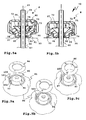
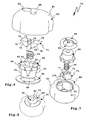
- the handle body 80 could be designed in one piece, which in the illustration according to FIG FIGS. 5a, 5b the case is, or even in several parts. From an assembly point of view, it is advantageous if the interior space 82 is accessible through a mounting opening 83 which can be closed by a cover 84.
- the cover 84 can be fastened to the housing 81, for example, by means of screw bolts or rivets, not shown, through screw openings 85. Also possible would be a thread on the outer circumference of the lid 84, which is screwed into a thread on the inner circumference of the mounting hole 83.
- the cover 84 has a passage opening 86 for a support portion 91 of the actuator body 90.
- a support surface 92 is provided, with which the actuator body 90 can be supported on an abutment 93, for example, the bracket 31.
- the support portion 91 is in Essentially cylindrical.
- the support surface 92 has a passage opening 94 for the tie rod 60, in particular its tie rod 64.
- the actuator body 90 projects with the free end of the support portion 91 in front of the lid 84 closed by the housing 81 of the handle body 80, so that the actuating body 90 on the Abutment 93 can be supported to be displaced into the interior 82 into it.
- the actuator body 90 is movably mounted with respect to the handle body 80.
- the handle body 80 is guided, for example, through the inner circumference of the passage opening 86, on which slides the cylindrical outer periphery of the support portion 91 along.
- the passage opening 86 is circular, corresponding to the outer periphery of the support portion 91, so that the actuating body 90 with respect to the passage opening 86 is rotatable.
- a rotation or a rotational drive for example, by a projection on the outer circumference of the support portion 91 which engages in a recess at the passage opening 86 (or vice versa), by a toothing between the two components or the like. It is useful, however, if the actuating body 90, while rotatably on the handle body 80, but axially along a defined by the tie rod 64 Verstellachse 69 movable.
- the tie rod 64 penetrates not only the actuator body 90 (passage opening 94), but also the handle body 80, namely at a tie rod passage opening 88 on a top wall 87 of the housing 81st
- a rotational drive between the handle body 80 and the actuator body 90 is realized by a sprocket 95 of the actuator body 90 and a lock 100 which is rotationally fixed with respect to the handle body 80.
- the lock 100 is shown only schematically and inserted, for example, in a passage opening or insertion opening 89 on the top wall 87.
- the ring gear 95 is located on one of the support surface 92 opposite side of the actuator body 90 and protrudes radially outward in front of the cylindrical outer periphery 96 of the support portion 91.
- the toothing of the ring gear 95 is rounded, i. between teeth 97 of the ring gear 95 are provided rounded portions.
- the lock 100 When the clamping nut assembly 70 is unlocked, the lock 100 is thus in its open position (FIG. FIG. 9a ), engages a driving contour, in this case a cylinder contour 101, of the lock 100 in one of the recesses between the teeth 97 a. As a result, a rotational drive between the lock 100, which in turn sits firmly in the handle body 80 and ultimately realized a rotational drive between the handle body 80 and the actuator body 90.
- a driving contour in this case a cylinder contour 101
- the rotational drive between the clamping nut 71 and the actuator body 90 is realized by a polygonal receptacle 99 in which the Spannmuttermaschine 72, which also have a polygonal contour on the outside, rotationally fixed, but axially adjustable with respect to the adjustment 69, are added.
- the two Spannmuttermaschine 72 are designed as wedge pieces.
- the Spannmuttermaschine 72 have on its threaded portion 66 facing the screw side 73 cylindrical recesses with internal threads 74, which are in the engaged position E into engagement with the threaded portion 66.
- an inclined surface 76 On one of the oblique surface side 75 opposite inclined surface side of a respective Spannmutterteils 72 is an inclined surface 76, with which the Spannmutterteil 72 slides on an inclined surface 98 of the actuator body 90 along.
- the inclined surfaces 98 are provided on a receptacle 99 of the actuating body 90, in which the two Spannmuttermaschine 72 are substantially received.
- a distance between the inclined surfaces 76, 98 of the adjustment axis 69 is smaller in the region of the support surface 92 than at a greater distance from the support surface 92.
- the inclined surfaces 76, 98 are thus inclined obliquely to the support surface 92.
- the inclined surfaces 76, 98 form components of a bevel gear or wedge gear 29 for adjusting the Spannmuttermaschine 72 in the engaged position E.
- the receptacle 99 also comprises a spring receptacle 27, in which a spring 25 of a spring assembly 26 is accommodated.
- the spring 25 is supported on the one hand on the actuating body 90 and on the other hand on the two Spannmutter matter 72, namely on a spring support side 77.
- the spring assembly 26 is supported on the bottom of the receptacle 99 from.
- the spring support side 77 extends between the respective screw side 73 and the inclined surface side 75 of a Spannmutterteils 72nd
- the Spannmuttermaschine 72 with its handle body support sides 78, ie the spring support sides 77 opposite sides, supported on the handle body 80, for example on the top wall 87 or disposed thereon support projections ( FIGS. 5a, 5b ).
- the spring assembly 26 acts on the Spannmuttermaschine 72 in the release position F ( FIG. 5a ).
- the operation of the clamping nut assembly 70 is as follows: As long as the support surface is not yet supported on the abutment 93 ( FIG. 5a ), which holds on the actuating body 90 spring assembly 26 holds the Spannmuttermaschine 72 in the release position F. Here, the actuating body 90 is supported against the force of the spring assembly 26 on the handle body 80, for example, at the bottom of the housing 81 or in the multi-part design according to FIGS. 6 to 9c on the lid 84.
- an edge projection of the actuating body 90 in this case, for example, the ring gear 95, serves as a support.
- the clamping nut arrangement 70 can be moved freely along the threaded section 66 without rotational actuation, ie. along the adjustment axis 69.
- the clamping nut 71 can be adjusted by applying force in the direction of the abutment 93 in the engaged position E. For example, an operator presses on the top wall 87.
- the handle body 80 loads the tension nut parts 72 in the direction of the abutment 93 against the spring force of the spring arrangement 26.
- the tension nut parts 72 slide with their inclined surfaces 76 along the corresponding inclined surfaces 98 of the actuating body 90, so that the internal thread 74 in the direction of the adjustment axis 69, ie towards the threaded portion 66 toward, be relocated and finally engage in this.
- the clamping nut 71 can be screwed to the abutment 93 out. A loosening of the clamping nut 70 is thereby prevented that the clamping nut 71 presses the actuating body 90 in the direction of the abutment 93, but this can not escape due to the abutment 93 and applied via the wedge gear 29, the two Spannmuttermaschine 72 in the engagement position E with a force ,
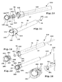
- Fastening device 130 shown partially have similar components as the previously explained fastener 30. As far as the components are the same or the same, the same reference numerals are used and are not explained in detail. To illustrate differences, the reference numerals in the fastener 130 by 100, in the fastener 230 increased by 200.
- the fastening devices 130, 230 are only partially shown, ie they may be provided for example with the bracket 31 and are suitably operated by means of a clamping nut, preferably with a clamping nut according to the invention, described later in detail, which is not shown for reasons of simplicity.
- the fastening device 130 shows a different connection concept compared to the fastening device 30 for the connection between the clamp and the tie rod.
- a clamp 140 of the fastening device 130 has on its annular body 141 annular body-exciting 142, where tie rod holders 146 are provided.
- the tie rod retainers 146 are not configured as recesses or receptacles or have the same, but have pull projections.
- the tension projections 147 serve to engage in tension receptacles 162 of a tie rod 160.
- the tension receptacles 162 are arranged on a tension abutment element 161 of the tie rod 160.
- the ring body 141 has a certain flexibility, so that it can be clipped to the carrier body 23 quasi. He can be widened until he surrounds the carrier body 23 or the bracket 21 and receives in its annular inner cross section 43.
- the two ring-body exciting 42 are then, as in FIG. 10 shown, approximately radially or parallel to a plane extending from the center of the inner cross section 43 radial line in parallel. Then, in cross-section, for example, round, preferably circular, pulling projections 147 in the manner of plug-in projections in the form-fitting receiving Switzerlandfactn 162 are inserted.
- the Switzerlandfactn 162 have a keyhole-like shape, wherein a substantially round, the Wervorsprünge 147 receiving portion of the Wergoingn 162 has a larger inner cross-section, in this case to the Buchvorsprüngen 147 has a circular inner cross-section, as on one side free openings 163, for receiving protruding sections 148 of the annular body-exciting 142 are provided.
- the Switzerlandwiderlagerelement 161 is configured block-shaped, for example, substantially cuboid, and is arranged at the end of the tie rod 64 of the tie rod 160.
- a clamping body 150 is provided, which does not affect the region of the annular body-exciting 42, unlike the clamping body 50, but the circumference of the annular body 141 in the sense of tensioning in the direction of the inner cross section 43 acted upon.
- the clamping body 150 is designed as a kind of clamping housing.
- Inner sides of side walls 131 of the clamping body 150 extend obliquely to the clamping movement path 37, so that they slide in a pulling movement of the tie rod 160 into the interior of the clamping body 150 / clamping housing into the peripheral outer sides 180 of the annular body 140 and this in the sense of narrowing the inner cross section 43 act in particular radially inward.
- An additional clamping effect or holding effect unfolds a Anpresskontur 133 of the clamping body 150.
- the Anpresskontur 133 is advantageously provided on a front side of a front wall 132.
- two contact contours 133 are provided on opposite front walls 132 of the clamping body 150.
- the Anpresskonturen 133 serve for pressing or pressing the clamping body 50 against the support body 23.
- the Anpresskonturen 133 In a round, for example, in the outer cross-section support body 23, e.g. a tube, the Anpresskonturen 133 have a correspondingly round, for example, circular course, which of course other Anpresskontur geometries are possible in adaptation to other outer contours of support bodies.
- the annular body 41 or 141 could be annularly closed, ie, for example, between the two annular body-exciting 42, 142 a connection, preferably with a sliding and / or pivotable and / or elastic connecting element, is present.
- the attachment device 230 is similar in construction to the connection concept between its tie rod 260 and its clamp 240 as the attachment means 30.
- the tie rod receptacles 47 are thus substantially U-shaped.
- Contours 280, 281 are provided on opposite sides of the tensile abutment element 262 and the tie rod receptacles 247 receiving this, for example at the bottom of the tie rod receptacles 47.
- These contours 280, 281 can be configured as form-fitting contours, so that the two components engage in one another in a form-fitting manner. Thus, an additional support is achieved.
- a kind of locking seat may be desired, so that the contours 280, 281 form latching contours.
- the contours 280, 281 form distance contours, which are expediently resilient, that the annular body-exciting 242 are transversely to the clamping path 37 toward each other or away from each other movable.
- the connecting element 282 is expediently designed as a film hinge.
- the connector 282 has two relatively movably mounted portions 283. The portions 283, in turn, are preferably movable with respect to the annular exciter 242, e.g. swiveling or kink-movable.
- annular body 241 Although a circular shape is expedient, it is not absolutely necessary.
- the leg sections 285 have angled, for example, approximately right-angled sections 286, 287 to each other. From the respective section 287 is the annular body-exciting 242 before or is formed thereby.
- a relatively long support projection 244 protrudes at the inside of the section 287 assigned to the inner cross section 43, so that the support projections 44, 244 define a substantially annular interior or retention space which is in any case adapted to the outer contour of the support body 23.
- At least one of the side walls 288, preferably two opposite side walls 288, have an oblique course transversely to the clamping movement path 37, so that their inner sides define inclined surfaces 56.
- all side walls 288 have this oblique course, so that the clamping body 250 can press or press its clamping function onto the outer sides of the annular body tensioning end 42 in a plurality of rotational positions relative to the tensioning movement path 37.
- These outsides are expediently designed as inclined surfaces (inclined surfaces 38).
Landscapes
- Engineering & Computer Science (AREA)
- General Engineering & Computer Science (AREA)
- Mechanical Engineering (AREA)
- Clamps And Clips (AREA)
Applications Claiming Priority (1)
| Application Number | Priority Date | Filing Date | Title |
|---|---|---|---|
| DE200910039820 DE102009039820A1 (de) | 2009-09-02 | 2009-09-02 | Befestigungseinrichtung mit einer Schelle |
Publications (2)
| Publication Number | Publication Date |
|---|---|
| EP2292471A1 true EP2292471A1 (fr) | 2011-03-09 |
| EP2292471B1 EP2292471B1 (fr) | 2013-03-27 |
Family
ID=43014248
Family Applications (1)
| Application Number | Title | Priority Date | Filing Date |
|---|---|---|---|
| EP10009113A Active EP2292471B1 (fr) | 2009-09-02 | 2010-09-02 | Dispositif de fixation doté d'un étrier |
Country Status (2)
| Country | Link |
|---|---|
| EP (1) | EP2292471B1 (fr) |
| DE (1) | DE102009039820A1 (fr) |
Cited By (4)
| Publication number | Priority date | Publication date | Assignee | Title |
|---|---|---|---|---|
| US9376065B2 (en) | 2013-07-26 | 2016-06-28 | Thule Sweden Ab | Anchor on a load carrier for a bicycle through-axle |
| CN107176289A (zh) * | 2017-05-24 | 2017-09-19 | 深圳大学 | 飞行器 |
| GB2563594A (en) * | 2017-06-19 | 2018-12-26 | Jaguar Land Rover Ltd | Releasable connector for a vehicle |
| CN114041881A (zh) * | 2022-01-10 | 2022-02-15 | 极限人工智能(北京)有限公司 | 器械夹持装置和微创手术机器人 |
Families Citing this family (3)
| Publication number | Priority date | Publication date | Assignee | Title |
|---|---|---|---|---|
| DE102012010049B4 (de) * | 2012-05-22 | 2015-11-26 | Springer Gmbh | Beidseitiger Schwenkarm für ein Werkstückhalteelement, insbesondere einen Werkstückgreifer insbesondere zum Halten und/oder Transportieren von Karosserieteilen im Kraftfahrzeug-Rohbau |
| DE202014101765U1 (de) | 2014-04-14 | 2015-07-17 | Carman Enterprise Co., Ltd. | Befestigungsstrebe zum Sichern eines Fahrrads auf Fahrradträgern |
| CN110154913A (zh) * | 2019-04-25 | 2019-08-23 | 兰庆 | 车顶装备物品电动收纳盒 |
Citations (3)
| Publication number | Priority date | Publication date | Assignee | Title |
|---|---|---|---|---|
| FR1016817A (fr) * | 1950-04-28 | 1952-11-24 | Système de fixation réglable pour objets cylindriques | |
| DE4304239A1 (de) * | 1993-02-12 | 1994-08-18 | Rixen & Kaul Gmbh | Befestigungsvorrichtung für Zubehör an Rohren und Stangen |
| EP1233192A2 (fr) * | 2001-02-20 | 2002-08-21 | Wolfgang Dipl.-Ing. Rixen | Raccord pour tube à élément de connexion |
Family Cites Families (1)
| Publication number | Priority date | Publication date | Assignee | Title |
|---|---|---|---|---|
| PL2212156T3 (pl) * | 2007-11-21 | 2014-04-30 | Thule Sweden Ab | Zespół wspornika do mocowania rowerów stosowany wraz z bagażnikiem samochodowym |
-
2009
- 2009-09-02 DE DE200910039820 patent/DE102009039820A1/de not_active Withdrawn
-
2010
- 2010-09-02 EP EP10009113A patent/EP2292471B1/fr active Active
Patent Citations (3)
| Publication number | Priority date | Publication date | Assignee | Title |
|---|---|---|---|---|
| FR1016817A (fr) * | 1950-04-28 | 1952-11-24 | Système de fixation réglable pour objets cylindriques | |
| DE4304239A1 (de) * | 1993-02-12 | 1994-08-18 | Rixen & Kaul Gmbh | Befestigungsvorrichtung für Zubehör an Rohren und Stangen |
| EP1233192A2 (fr) * | 2001-02-20 | 2002-08-21 | Wolfgang Dipl.-Ing. Rixen | Raccord pour tube à élément de connexion |
Cited By (7)
| Publication number | Priority date | Publication date | Assignee | Title |
|---|---|---|---|---|
| US9376065B2 (en) | 2013-07-26 | 2016-06-28 | Thule Sweden Ab | Anchor on a load carrier for a bicycle through-axle |
| CN107176289A (zh) * | 2017-05-24 | 2017-09-19 | 深圳大学 | 飞行器 |
| CN107176289B (zh) * | 2017-05-24 | 2023-04-18 | 深圳大学 | 飞行器 |
| GB2563594A (en) * | 2017-06-19 | 2018-12-26 | Jaguar Land Rover Ltd | Releasable connector for a vehicle |
| GB2563594B (en) * | 2017-06-19 | 2020-01-22 | Jaguar Land Rover Ltd | Releasable connector for a vehicle |
| CN114041881A (zh) * | 2022-01-10 | 2022-02-15 | 极限人工智能(北京)有限公司 | 器械夹持装置和微创手术机器人 |
| CN114041881B (zh) * | 2022-01-10 | 2022-04-12 | 极限人工智能(北京)有限公司 | 器械夹持装置和微创手术机器人 |
Also Published As
| Publication number | Publication date |
|---|---|
| DE102009039820A1 (de) | 2011-03-03 |
| EP2292471B1 (fr) | 2013-03-27 |
| DE102009039820A8 (de) | 2011-06-01 |
Similar Documents
| Publication | Publication Date | Title |
|---|---|---|
| EP2292471B1 (fr) | Dispositif de fixation doté d'un étrier | |
| DE10147588B4 (de) | Befestigungskloben zur Halterung von Gegenständen an einer Profilschiene | |
| DE102009039822A1 (de) | Befestigungseinrichtung mit einer Spannmutteranordnung | |
| DE202012102159U1 (de) | Lenksäule für ein Kraftfahrzeug | |
| DE102008002834B4 (de) | Zusammenklappbarer Schiebewagen für Kinder und/oder Puppen | |
| EP3409502A1 (fr) | Masse d'alourdissement de roue pour un véhicule utilitaire | |
| EP0754595B1 (fr) | Système variable de fixation rapide d?un coffre de toit sur les transverses d'une galerie de toit | |
| DE102009022622A1 (de) | Kraftfahrzeuganbaukomponente, insbesondere Lastenträger oder Anhängerkupplung | |
| DE202019005604U1 (de) | Vorrichtung zum Verbinden zweier Gegenstände | |
| DE102014211138A1 (de) | Vorrichtung zum manuellen oder elektromotorischen Verstellen und/oder Feststellen eines ersten Fahrzeugteils und eines zweiten Fahrzeugteils relativ zueinander | |
| DE19860264A1 (de) | Wischeranlage für ein Kraftfahrzeug | |
| EP2497701A1 (fr) | Plateforme pivotante pour un véhicule articulé | |
| DE102004059339A1 (de) | Ratschenspannvorrichtung zum Spannen von Gegenständen wie Gurten und Planen | |
| DE102014014427A1 (de) | Stielgeführtes Werkzeug und Stützvorrichtung zum Abstellen eines stielgeführten Werkzeuges | |
| DE102009005997A1 (de) | Stützfuß für Kraftschrauber | |
| EP4006241A1 (fr) | Dispositif de maintien pouvant être monté sur un poteau et dispositif de maintien de douchette sanitaire | |
| EP2292469B1 (fr) | Dispositif de fixation doté d'un étrier | |
| DE10321347B4 (de) | Halterungsvorrichtung für Dachkoffer | |
| EP2345558B1 (fr) | Dispositif de serrage pour un support de véhicule automobile ou pour un attelage | |
| EP2316673B1 (fr) | Dispositif de liaison pour un attelage ou un support de charge | |
| DE2747096A1 (de) | Kofferraumdeckelhalter | |
| DE202017103040U1 (de) | Trägeranordnung für ein Fahrzeug | |
| DE102007029130B4 (de) | Halter für Gebrauchs-Gegenstände | |
| DE202021003452U1 (de) | Spindelspanner | |
| EP0572873A1 (fr) | Dispositif de raccordement |
Legal Events
| Date | Code | Title | Description |
|---|---|---|---|
| PUAI | Public reference made under article 153(3) epc to a published international application that has entered the european phase |
Free format text: ORIGINAL CODE: 0009012 |
|
| AK | Designated contracting states |
Kind code of ref document: A1 Designated state(s): AL AT BE BG CH CY CZ DE DK EE ES FI FR GB GR HR HU IE IS IT LI LT LU LV MC MK MT NL NO PL PT RO SE SI SK SM TR |
|
| AX | Request for extension of the european patent |
Extension state: BA ME RS |
|
| RIN1 | Information on inventor provided before grant (corrected) |
Inventor name: RECKER, ANDREAS Inventor name: AUFDERHEIDE, REINHOLD Inventor name: HERMBUSCH, GERHARD |
|
| 17P | Request for examination filed |
Effective date: 20110831 |
|
| GRAP | Despatch of communication of intention to grant a patent |
Free format text: ORIGINAL CODE: EPIDOSNIGR1 |
|
| GRAS | Grant fee paid |
Free format text: ORIGINAL CODE: EPIDOSNIGR3 |
|
| GRAA | (expected) grant |
Free format text: ORIGINAL CODE: 0009210 |
|
| AK | Designated contracting states |
Kind code of ref document: B1 Designated state(s): AL AT BE BG CH CY CZ DE DK EE ES FI FR GB GR HR HU IE IS IT LI LT LU LV MC MK MT NL NO PL PT RO SE SI SK SM TR |
|
| REG | Reference to a national code |
Ref country code: GB Ref legal event code: FG4D Free format text: NOT ENGLISH |
|
| REG | Reference to a national code |
Ref country code: CH Ref legal event code: EP |
|
| REG | Reference to a national code |
Ref country code: AT Ref legal event code: REF Ref document number: 603167 Country of ref document: AT Kind code of ref document: T Effective date: 20130415 |
|
| REG | Reference to a national code |
Ref country code: IE Ref legal event code: FG4D Free format text: LANGUAGE OF EP DOCUMENT: GERMAN |
|
| REG | Reference to a national code |
Ref country code: DE Ref legal event code: R096 Ref document number: 502010002675 Country of ref document: DE Effective date: 20130523 |
|
| PG25 | Lapsed in a contracting state [announced via postgrant information from national office to epo] |
Ref country code: BG Free format text: LAPSE BECAUSE OF FAILURE TO SUBMIT A TRANSLATION OF THE DESCRIPTION OR TO PAY THE FEE WITHIN THE PRESCRIBED TIME-LIMIT Effective date: 20130627 Ref country code: SE Free format text: LAPSE BECAUSE OF FAILURE TO SUBMIT A TRANSLATION OF THE DESCRIPTION OR TO PAY THE FEE WITHIN THE PRESCRIBED TIME-LIMIT Effective date: 20130327 Ref country code: NO Free format text: LAPSE BECAUSE OF FAILURE TO SUBMIT A TRANSLATION OF THE DESCRIPTION OR TO PAY THE FEE WITHIN THE PRESCRIBED TIME-LIMIT Effective date: 20130627 Ref country code: LT Free format text: LAPSE BECAUSE OF FAILURE TO SUBMIT A TRANSLATION OF THE DESCRIPTION OR TO PAY THE FEE WITHIN THE PRESCRIBED TIME-LIMIT Effective date: 20130327 |
|
| REG | Reference to a national code |
Ref country code: LT Ref legal event code: MG4D |
|
| PG25 | Lapsed in a contracting state [announced via postgrant information from national office to epo] |
Ref country code: SI Free format text: LAPSE BECAUSE OF FAILURE TO SUBMIT A TRANSLATION OF THE DESCRIPTION OR TO PAY THE FEE WITHIN THE PRESCRIBED TIME-LIMIT Effective date: 20130327 Ref country code: FI Free format text: LAPSE BECAUSE OF FAILURE TO SUBMIT A TRANSLATION OF THE DESCRIPTION OR TO PAY THE FEE WITHIN THE PRESCRIBED TIME-LIMIT Effective date: 20130327 Ref country code: LV Free format text: LAPSE BECAUSE OF FAILURE TO SUBMIT A TRANSLATION OF THE DESCRIPTION OR TO PAY THE FEE WITHIN THE PRESCRIBED TIME-LIMIT Effective date: 20130327 Ref country code: GR Free format text: LAPSE BECAUSE OF FAILURE TO SUBMIT A TRANSLATION OF THE DESCRIPTION OR TO PAY THE FEE WITHIN THE PRESCRIBED TIME-LIMIT Effective date: 20130628 |
|
| REG | Reference to a national code |
Ref country code: NL Ref legal event code: VDEP Effective date: 20130327 |
|
| PG25 | Lapsed in a contracting state [announced via postgrant information from national office to epo] |
Ref country code: HR Free format text: LAPSE BECAUSE OF FAILURE TO SUBMIT A TRANSLATION OF THE DESCRIPTION OR TO PAY THE FEE WITHIN THE PRESCRIBED TIME-LIMIT Effective date: 20130327 |
|
| PG25 | Lapsed in a contracting state [announced via postgrant information from national office to epo] |
Ref country code: CZ Free format text: LAPSE BECAUSE OF FAILURE TO SUBMIT A TRANSLATION OF THE DESCRIPTION OR TO PAY THE FEE WITHIN THE PRESCRIBED TIME-LIMIT Effective date: 20130327 Ref country code: IS Free format text: LAPSE BECAUSE OF FAILURE TO SUBMIT A TRANSLATION OF THE DESCRIPTION OR TO PAY THE FEE WITHIN THE PRESCRIBED TIME-LIMIT Effective date: 20130727 Ref country code: RO Free format text: LAPSE BECAUSE OF FAILURE TO SUBMIT A TRANSLATION OF THE DESCRIPTION OR TO PAY THE FEE WITHIN THE PRESCRIBED TIME-LIMIT Effective date: 20130327 Ref country code: PT Free format text: LAPSE BECAUSE OF FAILURE TO SUBMIT A TRANSLATION OF THE DESCRIPTION OR TO PAY THE FEE WITHIN THE PRESCRIBED TIME-LIMIT Effective date: 20130729 Ref country code: SK Free format text: LAPSE BECAUSE OF FAILURE TO SUBMIT A TRANSLATION OF THE DESCRIPTION OR TO PAY THE FEE WITHIN THE PRESCRIBED TIME-LIMIT Effective date: 20130327 Ref country code: ES Free format text: LAPSE BECAUSE OF FAILURE TO SUBMIT A TRANSLATION OF THE DESCRIPTION OR TO PAY THE FEE WITHIN THE PRESCRIBED TIME-LIMIT Effective date: 20130708 Ref country code: EE Free format text: LAPSE BECAUSE OF FAILURE TO SUBMIT A TRANSLATION OF THE DESCRIPTION OR TO PAY THE FEE WITHIN THE PRESCRIBED TIME-LIMIT Effective date: 20130327 Ref country code: NL Free format text: LAPSE BECAUSE OF FAILURE TO SUBMIT A TRANSLATION OF THE DESCRIPTION OR TO PAY THE FEE WITHIN THE PRESCRIBED TIME-LIMIT Effective date: 20130327 |
|
| PG25 | Lapsed in a contracting state [announced via postgrant information from national office to epo] |
Ref country code: CY Free format text: LAPSE BECAUSE OF FAILURE TO SUBMIT A TRANSLATION OF THE DESCRIPTION OR TO PAY THE FEE WITHIN THE PRESCRIBED TIME-LIMIT Effective date: 20130327 Ref country code: PL Free format text: LAPSE BECAUSE OF FAILURE TO SUBMIT A TRANSLATION OF THE DESCRIPTION OR TO PAY THE FEE WITHIN THE PRESCRIBED TIME-LIMIT Effective date: 20130327 |
|
| PG25 | Lapsed in a contracting state [announced via postgrant information from national office to epo] |
Ref country code: DK Free format text: LAPSE BECAUSE OF FAILURE TO SUBMIT A TRANSLATION OF THE DESCRIPTION OR TO PAY THE FEE WITHIN THE PRESCRIBED TIME-LIMIT Effective date: 20130327 |
|
| PLBE | No opposition filed within time limit |
Free format text: ORIGINAL CODE: 0009261 |
|
| STAA | Information on the status of an ep patent application or granted ep patent |
Free format text: STATUS: NO OPPOSITION FILED WITHIN TIME LIMIT |
|
| PG25 | Lapsed in a contracting state [announced via postgrant information from national office to epo] |
Ref country code: IT Free format text: LAPSE BECAUSE OF FAILURE TO SUBMIT A TRANSLATION OF THE DESCRIPTION OR TO PAY THE FEE WITHIN THE PRESCRIBED TIME-LIMIT Effective date: 20130327 |
|
| 26N | No opposition filed |
Effective date: 20140103 |
|
| BERE | Be: lapsed |
Owner name: WESTFALIA - AUTOMOTIVE G.M.B.H. Effective date: 20130930 |
|
| REG | Reference to a national code |
Ref country code: DE Ref legal event code: R097 Ref document number: 502010002675 Country of ref document: DE Effective date: 20140103 |
|
| PG25 | Lapsed in a contracting state [announced via postgrant information from national office to epo] |
Ref country code: MC Free format text: LAPSE BECAUSE OF FAILURE TO SUBMIT A TRANSLATION OF THE DESCRIPTION OR TO PAY THE FEE WITHIN THE PRESCRIBED TIME-LIMIT Effective date: 20130327 |
|
| REG | Reference to a national code |
Ref country code: IE Ref legal event code: MM4A |
|
| PG25 | Lapsed in a contracting state [announced via postgrant information from national office to epo] |
Ref country code: IE Free format text: LAPSE BECAUSE OF NON-PAYMENT OF DUE FEES Effective date: 20130902 Ref country code: BE Free format text: LAPSE BECAUSE OF NON-PAYMENT OF DUE FEES Effective date: 20130930 |
|
| REG | Reference to a national code |
Ref country code: DE Ref legal event code: R082 Ref document number: 502010002675 Country of ref document: DE Representative=s name: BREGENZER, MICHAEL, DIPL.-ING., DE Ref country code: DE Ref legal event code: R082 Ref document number: 502010002675 Country of ref document: DE Representative=s name: PATENTANWAELTE BREGENZER UND REULE PARTNERSCHA, DE |
|
| REG | Reference to a national code |
Ref country code: DE Ref legal event code: R082 Ref document number: 502010002675 Country of ref document: DE Representative=s name: PATENTANWAELTE BREGENZER UND REULE PARTNERSCHA, DE |
|
| REG | Reference to a national code |
Ref country code: CH Ref legal event code: PL |
|
| GBPC | Gb: european patent ceased through non-payment of renewal fee |
Effective date: 20140902 |
|
| PG25 | Lapsed in a contracting state [announced via postgrant information from national office to epo] |
Ref country code: SM Free format text: LAPSE BECAUSE OF FAILURE TO SUBMIT A TRANSLATION OF THE DESCRIPTION OR TO PAY THE FEE WITHIN THE PRESCRIBED TIME-LIMIT Effective date: 20130327 |
|
| PG25 | Lapsed in a contracting state [announced via postgrant information from national office to epo] |
Ref country code: TR Free format text: LAPSE BECAUSE OF FAILURE TO SUBMIT A TRANSLATION OF THE DESCRIPTION OR TO PAY THE FEE WITHIN THE PRESCRIBED TIME-LIMIT Effective date: 20130327 Ref country code: MT Free format text: LAPSE BECAUSE OF FAILURE TO SUBMIT A TRANSLATION OF THE DESCRIPTION OR TO PAY THE FEE WITHIN THE PRESCRIBED TIME-LIMIT Effective date: 20130327 |
|
| PG25 | Lapsed in a contracting state [announced via postgrant information from national office to epo] |
Ref country code: LI Free format text: LAPSE BECAUSE OF NON-PAYMENT OF DUE FEES Effective date: 20140930 Ref country code: LU Free format text: LAPSE BECAUSE OF NON-PAYMENT OF DUE FEES Effective date: 20130902 Ref country code: MK Free format text: LAPSE BECAUSE OF FAILURE TO SUBMIT A TRANSLATION OF THE DESCRIPTION OR TO PAY THE FEE WITHIN THE PRESCRIBED TIME-LIMIT Effective date: 20130327 Ref country code: GB Free format text: LAPSE BECAUSE OF NON-PAYMENT OF DUE FEES Effective date: 20140902 Ref country code: HU Free format text: LAPSE BECAUSE OF FAILURE TO SUBMIT A TRANSLATION OF THE DESCRIPTION OR TO PAY THE FEE WITHIN THE PRESCRIBED TIME-LIMIT; INVALID AB INITIO Effective date: 20100902 Ref country code: CH Free format text: LAPSE BECAUSE OF NON-PAYMENT OF DUE FEES Effective date: 20140930 |
|
| REG | Reference to a national code |
Ref country code: FR Ref legal event code: PLFP Year of fee payment: 6 |
|
| REG | Reference to a national code |
Ref country code: FR Ref legal event code: PLFP Year of fee payment: 7 |
|
| REG | Reference to a national code |
Ref country code: AT Ref legal event code: MM01 Ref document number: 603167 Country of ref document: AT Kind code of ref document: T Effective date: 20150902 |
|
| PG25 | Lapsed in a contracting state [announced via postgrant information from national office to epo] |
Ref country code: AT Free format text: LAPSE BECAUSE OF NON-PAYMENT OF DUE FEES Effective date: 20150902 |
|
| REG | Reference to a national code |
Ref country code: FR Ref legal event code: PLFP Year of fee payment: 8 |
|
| REG | Reference to a national code |
Ref country code: FR Ref legal event code: PLFP Year of fee payment: 9 |
|
| PG25 | Lapsed in a contracting state [announced via postgrant information from national office to epo] |
Ref country code: AL Free format text: LAPSE BECAUSE OF FAILURE TO SUBMIT A TRANSLATION OF THE DESCRIPTION OR TO PAY THE FEE WITHIN THE PRESCRIBED TIME-LIMIT Effective date: 20130327 |
|
| PGFP | Annual fee paid to national office [announced via postgrant information from national office to epo] |
Ref country code: FR Payment date: 20210719 Year of fee payment: 12 |
|
| PG25 | Lapsed in a contracting state [announced via postgrant information from national office to epo] |
Ref country code: FR Free format text: LAPSE BECAUSE OF NON-PAYMENT OF DUE FEES Effective date: 20220930 |
|
| PGFP | Annual fee paid to national office [announced via postgrant information from national office to epo] |
Ref country code: DE Payment date: 20250929 Year of fee payment: 16 |