EP2292480B1 - Système de retardateur pour un véhicule automobile - Google Patents
Système de retardateur pour un véhicule automobile Download PDFInfo
- Publication number
- EP2292480B1 EP2292480B1 EP10169472A EP10169472A EP2292480B1 EP 2292480 B1 EP2292480 B1 EP 2292480B1 EP 10169472 A EP10169472 A EP 10169472A EP 10169472 A EP10169472 A EP 10169472A EP 2292480 B1 EP2292480 B1 EP 2292480B1
- Authority
- EP
- European Patent Office
- Prior art keywords
- closing element
- pressure
- valve
- retarder system
- valve piston
- Prior art date
- Legal status (The legal status is an assumption and is not a legal conclusion. Google has not performed a legal analysis and makes no representation as to the accuracy of the status listed.)
- Not-in-force
Links
- 239000012530 fluid Substances 0.000 claims description 35
- 230000005540 biological transmission Effects 0.000 description 4
- 238000004519 manufacturing process Methods 0.000 description 3
- 230000008878 coupling Effects 0.000 description 2
- 238000010168 coupling process Methods 0.000 description 2
- 238000005859 coupling reaction Methods 0.000 description 2
- 238000000034 method Methods 0.000 description 2
- 230000006978 adaptation Effects 0.000 description 1
- 230000006399 behavior Effects 0.000 description 1
- 239000000872 buffer Substances 0.000 description 1
- 230000006835 compression Effects 0.000 description 1
- 238000007906 compression Methods 0.000 description 1
- 230000007423 decrease Effects 0.000 description 1
- 230000001419 dependent effect Effects 0.000 description 1
- 238000006073 displacement reaction Methods 0.000 description 1
- 230000000694 effects Effects 0.000 description 1
- 210000003746 feather Anatomy 0.000 description 1
- 238000009434 installation Methods 0.000 description 1
- 230000010354 integration Effects 0.000 description 1
- 239000012528 membrane Substances 0.000 description 1
- 230000001629 suppression Effects 0.000 description 1
- 230000002459 sustained effect Effects 0.000 description 1
- 238000011144 upstream manufacturing Methods 0.000 description 1
Images
Classifications
-
- B—PERFORMING OPERATIONS; TRANSPORTING
- B60—VEHICLES IN GENERAL
- B60T—VEHICLE BRAKE CONTROL SYSTEMS OR PARTS THEREOF; BRAKE CONTROL SYSTEMS OR PARTS THEREOF, IN GENERAL; ARRANGEMENT OF BRAKING ELEMENTS ON VEHICLES IN GENERAL; PORTABLE DEVICES FOR PREVENTING UNWANTED MOVEMENT OF VEHICLES; VEHICLE MODIFICATIONS TO FACILITATE COOLING OF BRAKES
- B60T10/00—Control or regulation for continuous braking making use of fluid or powdered medium, e.g. for use when descending a long slope
- B60T10/02—Control or regulation for continuous braking making use of fluid or powdered medium, e.g. for use when descending a long slope with hydrodynamic brake
-
- F—MECHANICAL ENGINEERING; LIGHTING; HEATING; WEAPONS; BLASTING
- F16—ENGINEERING ELEMENTS AND UNITS; GENERAL MEASURES FOR PRODUCING AND MAINTAINING EFFECTIVE FUNCTIONING OF MACHINES OR INSTALLATIONS; THERMAL INSULATION IN GENERAL
- F16D—COUPLINGS FOR TRANSMITTING ROTATION; CLUTCHES; BRAKES
- F16D57/00—Liquid-resistance brakes; Brakes using the internal friction of fluids or fluid-like media, e.g. powders
- F16D57/04—Liquid-resistance brakes; Brakes using the internal friction of fluids or fluid-like media, e.g. powders with blades causing a directed flow, e.g. Föttinger type
-
- F—MECHANICAL ENGINEERING; LIGHTING; HEATING; WEAPONS; BLASTING
- F16—ENGINEERING ELEMENTS AND UNITS; GENERAL MEASURES FOR PRODUCING AND MAINTAINING EFFECTIVE FUNCTIONING OF MACHINES OR INSTALLATIONS; THERMAL INSULATION IN GENERAL
- F16K—VALVES; TAPS; COCKS; ACTUATING-FLOATS; DEVICES FOR VENTING OR AERATING
- F16K11/00—Multiple-way valves, e.g. mixing valves; Pipe fittings incorporating such valves
- F16K11/02—Multiple-way valves, e.g. mixing valves; Pipe fittings incorporating such valves with all movable sealing faces moving as one unit
- F16K11/06—Multiple-way valves, e.g. mixing valves; Pipe fittings incorporating such valves with all movable sealing faces moving as one unit comprising only sliding valves, i.e. sliding closure elements
- F16K11/065—Multiple-way valves, e.g. mixing valves; Pipe fittings incorporating such valves with all movable sealing faces moving as one unit comprising only sliding valves, i.e. sliding closure elements with linearly sliding closure members
- F16K11/07—Multiple-way valves, e.g. mixing valves; Pipe fittings incorporating such valves with all movable sealing faces moving as one unit comprising only sliding valves, i.e. sliding closure elements with linearly sliding closure members with cylindrical slides
- F16K11/0708—Multiple-way valves, e.g. mixing valves; Pipe fittings incorporating such valves with all movable sealing faces moving as one unit comprising only sliding valves, i.e. sliding closure elements with linearly sliding closure members with cylindrical slides comprising means to avoid jamming of the slide or means to modify the flow
Definitions
- the invention relates to a retarder system for a drive train of a motor vehicle, with a rotor and a stator, which are each equipped with blades and facing each other placed in a common housing, wherein a trained between the rotor and the stator working space via an external pressure source with a defined Amount of fluid corresponding to a switching position of a switching valve can be filled, which is designed in the manner of a directional control valve with a valve housing slidably guided in a valve piston and a fluid flow in a first switching position of the valve piston between at least one, connected to the working space working port and at least one pressure port of the pressure source allows while the at least one working port can be connected in a second switching position with at least one return port.
- a common embodiment of a retarder is a so-called hydrodynamic retarder, in which the flow energy of a fluid is used to decelerate the motor vehicle.
- a distinction is made between primary retarders in the arrangement between engine and transmission and secondary retarders in the arrangement between the transmission and drive axle.
- This control is usually represented by controlling a fluid circuit via valves.
- a hydrodynamic retarder for a motor vehicle having a rotor arranged on a shaft, which is coupled to the output shaft of a transmission and a stator, wherein rotor and stator are arranged in a housing which is connected to an oil circuit, which has a memory, a pump, a switching valve and a control arrangement.
- a control valve is provided that promotes the contents of the memory when it is supplied with compressed air via the high-pressure side in the retarder and controls in addition to the emptying of the memory and its filling.
- a retarder system for a drive train of a motor vehicle in which a defined amount of fluid from a circuit to a working space of a retarder can be supplied, wherein the working space is formed between a rotor and a stator.
- the work space is preceded by a changeover valve, which is designed in the manner of a directional control valve with a valve piston which is displaceably guided in a valve housing.
- a changeover valve which is designed in the manner of a directional control valve with a valve piston which is displaceably guided in a valve housing.
- a filling of the working space via an upstream pressure source in the form of a pump or an emptying of the working space is shown in a return.
- corresponding connections are provided on the valve housing.
- the invention comprises the technical teaching that at least one closing element which can be displaced relative to the valve piston is guided on a shaft of the valve piston, which is placed between shoulders of the valve piston.
- this closing element is coupled to one of the paragraphs via means which transfer the closing element into a position interrupting the fluid flow, as soon as the valve piston is in a switching position, in which the Working space is connected to the return and falls below a defined fluid pressure at the working port of the working space is recorded.
- the changeover valve is characterized due to the only minor change and the arrangement of the closing element on the valve piston by a low manufacturing effort and an extremely space-saving solution.
- the at least one closing element in the region of an outer diameter is additionally guided on the side placed by the return connection over an extension in a recess corresponding thereto. Due to the additional guidance of the closing element in the outer region, tilting of the same can be prevented during a displacement within the surrounding valve housing and at the same time a smaller gap dimension relative to the valve housing in the radial direction can be achieved.
- the means are accommodated in an interior, which is formed between the side of the at least one return port placed paragraph and the at least one closing element.
- the at least one closing element has a step on a side facing the pressure connection-side shoulder.
- a stop with a low, technical manufacturing effort is thereby formed during a movement of the closing element in the direction of the pressure connection side paragraph.
- the means are each formed by an elastic element.
- this elastic element is a spring in this case.
- the inventive Coupling of the closing element with the respective shoulder of the valve piston realize very space-saving, the definition of the pressure value from which a transfer takes place in the interrupting position, by selecting a corresponding spring stiffness can be displayed.
- the use of rubber buffers or membranes as elastic elements is also conceivable here.
- the means are formed by a control hydraulics. Consequently, a transfer to the interrupting position can take place by targeted actuation of this control hydraulics, so that changes in the defined pressure value of the fluid can also be realized without difficulty. Thus, an individual adaptation to the emptying behavior of the respective retarder can be made. At this point, however, the application of a pneumatic or electromagnetic control system comes into question.
- an end face of the valve piston can be acted upon by an actuating pressure, while a return spring is provided on an end face opposite thereto.
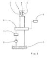
- Fig. 1 is a schematic view of the retarder system of the invention.
- the retarder system has a retarder 1, which receives in a housing a rotor 2 and a stator 3, each equipped with blades and facing each other form an intermediate working space 4.
- the retarder 1 is supplied with fluid in the form of oil from a reservoir 5 via a pressure source 6 in the form of a feed pump.
- the storage container 5 may be, for example, an oil sump of an adjacent motor vehicle transmission.
- the fluid sucked in via the pressure source 6 is subsequently conveyed to a control valve 7 (not shown in greater detail), which performs a pressure adjustment in accordance with the braking torque to be generated in the retarder 1.
- a switching valve 8 in the further course, which regulates the fluid flow to the working space 4 of the retarder 1 or out of the working space 4 by respectively associated switching positions.
- a switching valve 9 is provided, which can cause the corresponding switching positions by pressurizing.
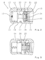
- Fig. 2 a sectional view of the switching valve 8 is shown.
- this is designed in the manner of a directional control valve which accommodates a valve piston 11 displaceably in a valve housing 10, wherein the valve piston 11 is spring-loaded at a front end via a return spring 12, while at an opposite end face a pressure chamber thirteenth is provided for pressurizing via the switching valve 9.
- the valve piston 11 furthermore has two shoulders 14 and 15, via which, depending on the axial position of the valve piston 11 in the valve housing 10, a fluid flow from a pressure port 16, which in the further course communicates with the pressure source 6, to a working port 17 of the retarder 1 or from the working port 17 to a return port 18 of the reservoir 5 is made possible.
- a closing element 19 is provided between the paragraphs 14 and 15, that is guided displaceably on the valve piston 11 with a central through hole 20. Furthermore, this closing element 19 has a circumferential extension 21, via which the closing element 19 in the region of its outer diameter in a this corresponding recess 22 of the paragraph 15 is guided. In this case, the closing element 19 and the shoulder 15 define an intermediate interior 23, in which a spring 24 is placed.
- Fig. 2 the switching valve 8 is shown in a first switching position, in which the valve piston 11 is acted upon in the region of the pressure chamber 13 with pressurized fluid and assumes the position shown under compression of the return spring 12.
- a flow of fluid from the pressure port 16 into the working port 17, ie from the pressure source 6 to the retarder 1 is made possible.
- the closing element 19 is pressed against the spring 24 against the shoulder 15. Consequently, the fluid can flow unhindered to the working port 17.
- the return spring 12 causes the valve piston 11 to be moved back axially in the direction of the pressure chamber 13. From a certain axial position of the paragraph 14 in this case closes the pressure port 16, while still pressed against the shoulder 15 closing element 19 releases the return port 18. From this point on, fluid can flow back into the return port 18 via the working connection 17. However, the increasing emptying of the retarder 1 has the effect that the fluid pressure at the working connection 17 also steadily decreases. From below a defined fluid pressure at the working port 17, which is preferably just above a pressure within the return to the reservoir 5, the pressure acting on the closing element 19 is no longer sufficient to compress the spring 24.
- valve piston 11 Upon renewed pressurization of the pressure chamber 13, the valve piston 11 is again moved in the direction opposite to the return spring 12, wherein the shoulder 14 again releases the pressure port 16 in this way from a certain position.
- the closing element 19 By then flowing back under pressure fluid, the closing element 19 is again pressed against the spring 24 to the shoulder 15 so that when reaching the final position of the valve piston 11 turn the in Fig. 2 shown switching position is taken.
Landscapes
- Engineering & Computer Science (AREA)
- General Engineering & Computer Science (AREA)
- Mechanical Engineering (AREA)
- Physics & Mathematics (AREA)
- Fluid Mechanics (AREA)
- Transportation (AREA)
- Transmission Of Braking Force In Braking Systems (AREA)
- Braking Arrangements (AREA)
Claims (8)
- Système de retardateur pour une chaîne cinématique d'un véhicule automobile, comprenant un rotor (2) et un stator (3), qui sont chacun munis d'aubes et qui, tournés l'un vers l'autre, sont placés dans un boîtier commun, un espace de travail (4) réalisé entre le rotor (2) et le stator (3) pouvant être rempli par le biais d'une source de pression externe (6) d'une quantité de fluide définie correspondant à une position de commutation d'une soupape d'inversion (8), qui est configurée à la manière d'une soupape de distribution avec un piston de soupape (11) guidé de manière déplaçable dans un boîtier de soupape (10) et qui permet un flux de fluide dans une première position de commutation du piston de soupape (11) entre au moins un raccord de travail (17) connecté à l'espace de travail (4) et au moins un raccord de pression (16) de la source de pression (6), tandis que l'au moins un raccord de travail (17) peut être connecté dans une deuxième position de commutation à au moins un raccord de retour (18), caractérisé en ce que sur une tige du piston de soupape (11) est guidé au moins un élément de fermeture (19) pouvant être fermé de manière relative par rapport au piston de soupape (11), lequel élément de fermeture est placé entre des épaulements (14, 15) du piston de soupape (11) et est accouplé à l'un des épaulements (15) par le biais de moyens qui transfèrent l'au moins un élément de fermeture (19) dans la deuxième position de commutation et à partir d'une pression en dessous d'une pression de fluide définie au niveau d'au moins un raccord de travail (17), le transfèrent dans une position interrompant le flux de fluide.
- Système de retardateur selon la revendication 1, caractérisé en ce que l'au moins un élément de fermeture (19) est guidé en outre dans la région d'un diamètre extérieur sur une distance (21) dans un évidement (22) correspondant, au niveau de l'épaulement (15) placé du côté de l'au moins un raccord de retour (18).
- Système de retardateur selon la revendication 2, caractérisé en ce que les moyens sont reçus dans un espace interne (23) qui est réalisé entre l'épaulement (15) placé du côté de l'au moins un raccord de retour (18) et l'au moins un élément de fermeture (19).
- Système de retardateur selon l'une quelconque des revendications 1 à 3, caractérisé en ce que l'au moins un élément de fermeture (19) présente un gradin (25) qui s'étend dans la direction de l'épaulement (14) prévu du côté de l'au moins un raccord de pression (16).
- Système de retardateur selon l'une quelconque des revendications précédentes, caractérisé en ce que les moyens sont formés par un élément élastique respectif.
- Système de retardateur selon la revendication 5, caractérisé en ce que l'élément élastique respectif est un ressort (24).
- Système de retardateur selon l'une quelconque des revendications 1 à 4, caractérisé en ce que les moyens sont formés par un système hydraulique de commande respectif.
- Système de retardateur selon l'une quelconque des revendications précédentes, caractérisé en ce qu'un côté frontal du piston de soupape (11) peut être sollicité par une pression d'actionnement, tandis qu'un ressort de rappel (12) est prévu sur un côté frontal opposé.
Applications Claiming Priority (1)
| Application Number | Priority Date | Filing Date | Title |
|---|---|---|---|
| DE102009029150A DE102009029150A1 (de) | 2009-09-03 | 2009-09-03 | Retardersystem für ein Kraftfahrzeug |
Publications (2)
| Publication Number | Publication Date |
|---|---|
| EP2292480A1 EP2292480A1 (fr) | 2011-03-09 |
| EP2292480B1 true EP2292480B1 (fr) | 2012-05-09 |
Family
ID=43027699
Family Applications (1)
| Application Number | Title | Priority Date | Filing Date |
|---|---|---|---|
| EP10169472A Not-in-force EP2292480B1 (fr) | 2009-09-03 | 2010-07-14 | Système de retardateur pour un véhicule automobile |
Country Status (3)
| Country | Link |
|---|---|
| EP (1) | EP2292480B1 (fr) |
| AT (1) | ATE556903T1 (fr) |
| DE (1) | DE102009029150A1 (fr) |
Cited By (1)
| Publication number | Priority date | Publication date | Assignee | Title |
|---|---|---|---|---|
| KR101666119B1 (ko) * | 2015-04-22 | 2016-10-14 | 한국파워트레인 주식회사 | 로터-스테이터의 간격 제어가 가능한 유체식 리타더 |
Family Cites Families (6)
| Publication number | Priority date | Publication date | Assignee | Title |
|---|---|---|---|---|
| DE2018652A1 (de) * | 1970-04-18 | 1971-12-02 | Daimler-Benz AG, 7000 Stuttgart-Untertürkheim | Hydrodynamische Bremse (Retarder) für Fahrzeuge, insbesondere Kraftfahrzeuge |
| DE19616426C1 (de) * | 1996-04-25 | 1997-08-14 | Voith Turbo Kg | Antriebseinheit mit einem Motor und einem Retarder |
| DE19833891A1 (de) * | 1998-07-28 | 2000-02-03 | Zahnradfabrik Friedrichshafen | Hydrodynamischer Retarder für ein Kraftfahrzeug |
| DE19860706A1 (de) * | 1998-12-30 | 2000-07-06 | Voith Turbo Kg | Hydrodynamischer Retarder mit Mitteln zum Erzeugen von Druckimpulsen |
| DE10149061A1 (de) | 2001-10-05 | 2003-04-24 | Zahnradfabrik Friedrichshafen | Hydrodynamischer Retarder für ein Kraftfahrzeug |
| DE102006008110A1 (de) * | 2006-02-20 | 2007-08-30 | Voith Turbo Gmbh & Co. Kg | Füllungssteuervorrichtung für eine hydrodynamische Maschine |
-
2009
- 2009-09-03 DE DE102009029150A patent/DE102009029150A1/de not_active Withdrawn
-
2010
- 2010-07-14 EP EP10169472A patent/EP2292480B1/fr not_active Not-in-force
- 2010-07-14 AT AT10169472T patent/ATE556903T1/de active
Cited By (1)
| Publication number | Priority date | Publication date | Assignee | Title |
|---|---|---|---|---|
| KR101666119B1 (ko) * | 2015-04-22 | 2016-10-14 | 한국파워트레인 주식회사 | 로터-스테이터의 간격 제어가 가능한 유체식 리타더 |
Also Published As
| Publication number | Publication date |
|---|---|
| ATE556903T1 (de) | 2012-05-15 |
| DE102009029150A1 (de) | 2011-03-10 |
| EP2292480A1 (fr) | 2011-03-09 |
Similar Documents
| Publication | Publication Date | Title |
|---|---|---|
| EP1592887B1 (fr) | Pompe haute pression | |
| EP2294316B1 (fr) | Pompe à piston d'un système hydraulique de freinage de véhicule | |
| EP2303652B1 (fr) | Soupape de réglage pour un système de freinage de véhicule et système de freinage de véhicule avec une soupape de ce type | |
| DE102013006990B4 (de) | Druckdämpfungsvorrichtung für Bremssystem | |
| EP1101035A1 (fr) | Pompe a piston | |
| DE102016222562A1 (de) | Pedalwegsimulator und Hydraulikblock mit einem Pedalwegsimulator | |
| EP1108141A1 (fr) | Pompe a piston | |
| EP2486280B1 (fr) | Pompe volumétrique rotative à palettes | |
| EP1558478B1 (fr) | Dispositif de pompage | |
| DE102017222546A1 (de) | Kolbenpumpe zur Förderung von Druckmittel in einem Druckmittelkreis | |
| EP1903238B1 (fr) | Système hydraulique | |
| EP0804686B1 (fr) | Pompe a piston | |
| DE19527402A1 (de) | Pumpe | |
| EP0850166A1 (fr) | Maitre-cylindre | |
| DE102012202904A1 (de) | Pumpenanordnung zum Erzeugen eines variablen Volumenstromes | |
| WO2008058801A1 (fr) | Pompe à piston pour un système de freinage de véhicule | |
| EP2292480B1 (fr) | Système de retardateur pour un véhicule automobile | |
| DE4402734C2 (de) | Bremsschlupf- und antriebsschlupfgeregelte Bremsanlage | |
| DE19751421A1 (de) | Kolbenpumpe | |
| DE4444381A1 (de) | Druckübersetzer | |
| WO1995025653A1 (fr) | Systeme de freinage hydraulique a regulation antipatinage et antiblocage | |
| EP1635071A2 (fr) | Système hydraulique, en particulier pour véhicules à moteur | |
| EP1810904A2 (fr) | Dispositif de pompe | |
| EP2049793B1 (fr) | Pompe à piston pour systèmes de freinage de véhicules, munie d'un piston | |
| DE102006061462A1 (de) | Elektrohydraulisches Pumpensystem |
Legal Events
| Date | Code | Title | Description |
|---|---|---|---|
| PUAI | Public reference made under article 153(3) epc to a published international application that has entered the european phase |
Free format text: ORIGINAL CODE: 0009012 |
|
| AK | Designated contracting states |
Kind code of ref document: A1 Designated state(s): AL AT BE BG CH CY CZ DE DK EE ES FI FR GB GR HR HU IE IS IT LI LT LU LV MC MK MT NL NO PL PT RO SE SI SK SM TR |
|
| AX | Request for extension of the european patent |
Extension state: BA ME RS |
|
| 17P | Request for examination filed |
Effective date: 20110802 |
|
| RIC1 | Information provided on ipc code assigned before grant |
Ipc: B60T 10/02 20060101ALI20110823BHEP Ipc: F16D 57/02 20060101ALI20110823BHEP Ipc: B60T 1/087 20060101AFI20110823BHEP Ipc: F16K 11/07 20060101ALI20110823BHEP |
|
| GRAP | Despatch of communication of intention to grant a patent |
Free format text: ORIGINAL CODE: EPIDOSNIGR1 |
|
| RIN1 | Information on inventor provided before grant (corrected) |
Inventor name: SAUTER, FRANK Inventor name: WANNINGER, HEINZ |
|
| GRAS | Grant fee paid |
Free format text: ORIGINAL CODE: EPIDOSNIGR3 |
|
| GRAA | (expected) grant |
Free format text: ORIGINAL CODE: 0009210 |
|
| AK | Designated contracting states |
Kind code of ref document: B1 Designated state(s): AL AT BE BG CH CY CZ DE DK EE ES FI FR GB GR HR HU IE IS IT LI LT LU LV MC MK MT NL NO PL PT RO SE SI SK SM TR |
|
| REG | Reference to a national code |
Ref country code: GB Ref legal event code: FG4D Free format text: NOT ENGLISH |
|
| REG | Reference to a national code |
Ref country code: AT Ref legal event code: REF Ref document number: 556903 Country of ref document: AT Kind code of ref document: T Effective date: 20120515 Ref country code: CH Ref legal event code: EP |
|
| REG | Reference to a national code |
Ref country code: IE Ref legal event code: FG4D Free format text: LANGUAGE OF EP DOCUMENT: GERMAN |
|
| REG | Reference to a national code |
Ref country code: SE Ref legal event code: TRGR |
|
| REG | Reference to a national code |
Ref country code: DE Ref legal event code: R096 Ref document number: 502010000697 Country of ref document: DE Effective date: 20120712 |
|
| REG | Reference to a national code |
Ref country code: NL Ref legal event code: VDEP Effective date: 20120509 |
|
| REG | Reference to a national code |
Ref country code: LT Ref legal event code: MG4D Effective date: 20120509 |
|
| PG25 | Lapsed in a contracting state [announced via postgrant information from national office to epo] |
Ref country code: NO Free format text: LAPSE BECAUSE OF FAILURE TO SUBMIT A TRANSLATION OF THE DESCRIPTION OR TO PAY THE FEE WITHIN THE PRESCRIBED TIME-LIMIT Effective date: 20120809 Ref country code: PL Free format text: LAPSE BECAUSE OF FAILURE TO SUBMIT A TRANSLATION OF THE DESCRIPTION OR TO PAY THE FEE WITHIN THE PRESCRIBED TIME-LIMIT Effective date: 20120509 Ref country code: IS Free format text: LAPSE BECAUSE OF FAILURE TO SUBMIT A TRANSLATION OF THE DESCRIPTION OR TO PAY THE FEE WITHIN THE PRESCRIBED TIME-LIMIT Effective date: 20120909 Ref country code: CY Free format text: LAPSE BECAUSE OF FAILURE TO SUBMIT A TRANSLATION OF THE DESCRIPTION OR TO PAY THE FEE WITHIN THE PRESCRIBED TIME-LIMIT Effective date: 20120509 Ref country code: LT Free format text: LAPSE BECAUSE OF FAILURE TO SUBMIT A TRANSLATION OF THE DESCRIPTION OR TO PAY THE FEE WITHIN THE PRESCRIBED TIME-LIMIT Effective date: 20120509 Ref country code: FI Free format text: LAPSE BECAUSE OF FAILURE TO SUBMIT A TRANSLATION OF THE DESCRIPTION OR TO PAY THE FEE WITHIN THE PRESCRIBED TIME-LIMIT Effective date: 20120509 |
|
| PGFP | Annual fee paid to national office [announced via postgrant information from national office to epo] |
Ref country code: SE Payment date: 20120711 Year of fee payment: 3 |
|
| PG25 | Lapsed in a contracting state [announced via postgrant information from national office to epo] |
Ref country code: SI Free format text: LAPSE BECAUSE OF FAILURE TO SUBMIT A TRANSLATION OF THE DESCRIPTION OR TO PAY THE FEE WITHIN THE PRESCRIBED TIME-LIMIT Effective date: 20120509 Ref country code: PT Free format text: LAPSE BECAUSE OF FAILURE TO SUBMIT A TRANSLATION OF THE DESCRIPTION OR TO PAY THE FEE WITHIN THE PRESCRIBED TIME-LIMIT Effective date: 20120910 Ref country code: LV Free format text: LAPSE BECAUSE OF FAILURE TO SUBMIT A TRANSLATION OF THE DESCRIPTION OR TO PAY THE FEE WITHIN THE PRESCRIBED TIME-LIMIT Effective date: 20120509 Ref country code: GR Free format text: LAPSE BECAUSE OF FAILURE TO SUBMIT A TRANSLATION OF THE DESCRIPTION OR TO PAY THE FEE WITHIN THE PRESCRIBED TIME-LIMIT Effective date: 20120810 Ref country code: HR Free format text: LAPSE BECAUSE OF FAILURE TO SUBMIT A TRANSLATION OF THE DESCRIPTION OR TO PAY THE FEE WITHIN THE PRESCRIBED TIME-LIMIT Effective date: 20120509 |
|
| PGFP | Annual fee paid to national office [announced via postgrant information from national office to epo] |
Ref country code: DE Payment date: 20120711 Year of fee payment: 3 |
|
| BERE | Be: lapsed |
Owner name: ZF FRIEDRICHSHAFEN A.G. Effective date: 20120731 |
|
| PG25 | Lapsed in a contracting state [announced via postgrant information from national office to epo] |
Ref country code: EE Free format text: LAPSE BECAUSE OF FAILURE TO SUBMIT A TRANSLATION OF THE DESCRIPTION OR TO PAY THE FEE WITHIN THE PRESCRIBED TIME-LIMIT Effective date: 20120509 Ref country code: NL Free format text: LAPSE BECAUSE OF FAILURE TO SUBMIT A TRANSLATION OF THE DESCRIPTION OR TO PAY THE FEE WITHIN THE PRESCRIBED TIME-LIMIT Effective date: 20120509 Ref country code: RO Free format text: LAPSE BECAUSE OF FAILURE TO SUBMIT A TRANSLATION OF THE DESCRIPTION OR TO PAY THE FEE WITHIN THE PRESCRIBED TIME-LIMIT Effective date: 20120509 Ref country code: DK Free format text: LAPSE BECAUSE OF FAILURE TO SUBMIT A TRANSLATION OF THE DESCRIPTION OR TO PAY THE FEE WITHIN THE PRESCRIBED TIME-LIMIT Effective date: 20120509 Ref country code: CZ Free format text: LAPSE BECAUSE OF FAILURE TO SUBMIT A TRANSLATION OF THE DESCRIPTION OR TO PAY THE FEE WITHIN THE PRESCRIBED TIME-LIMIT Effective date: 20120509 Ref country code: SK Free format text: LAPSE BECAUSE OF FAILURE TO SUBMIT A TRANSLATION OF THE DESCRIPTION OR TO PAY THE FEE WITHIN THE PRESCRIBED TIME-LIMIT Effective date: 20120509 |
|
| PG25 | Lapsed in a contracting state [announced via postgrant information from national office to epo] |
Ref country code: MC Free format text: LAPSE BECAUSE OF NON-PAYMENT OF DUE FEES Effective date: 20120731 Ref country code: IT Free format text: LAPSE BECAUSE OF FAILURE TO SUBMIT A TRANSLATION OF THE DESCRIPTION OR TO PAY THE FEE WITHIN THE PRESCRIBED TIME-LIMIT Effective date: 20120509 Ref country code: MK Free format text: LAPSE BECAUSE OF FAILURE TO SUBMIT A TRANSLATION OF THE DESCRIPTION OR TO PAY THE FEE WITHIN THE PRESCRIBED TIME-LIMIT Effective date: 20120509 |
|
| PLBE | No opposition filed within time limit |
Free format text: ORIGINAL CODE: 0009261 |
|
| STAA | Information on the status of an ep patent application or granted ep patent |
Free format text: STATUS: NO OPPOSITION FILED WITHIN TIME LIMIT |
|
| 26N | No opposition filed |
Effective date: 20130212 |
|
| REG | Reference to a national code |
Ref country code: FR Ref legal event code: ST Effective date: 20130329 |
|
| PG25 | Lapsed in a contracting state [announced via postgrant information from national office to epo] |
Ref country code: ES Free format text: LAPSE BECAUSE OF FAILURE TO SUBMIT A TRANSLATION OF THE DESCRIPTION OR TO PAY THE FEE WITHIN THE PRESCRIBED TIME-LIMIT Effective date: 20120820 Ref country code: FR Free format text: LAPSE BECAUSE OF NON-PAYMENT OF DUE FEES Effective date: 20120731 |
|
| REG | Reference to a national code |
Ref country code: IE Ref legal event code: MM4A |
|
| PG25 | Lapsed in a contracting state [announced via postgrant information from national office to epo] |
Ref country code: BE Free format text: LAPSE BECAUSE OF NON-PAYMENT OF DUE FEES Effective date: 20120731 |
|
| REG | Reference to a national code |
Ref country code: DE Ref legal event code: R097 Ref document number: 502010000697 Country of ref document: DE Effective date: 20130212 |
|
| PG25 | Lapsed in a contracting state [announced via postgrant information from national office to epo] |
Ref country code: BG Free format text: LAPSE BECAUSE OF FAILURE TO SUBMIT A TRANSLATION OF THE DESCRIPTION OR TO PAY THE FEE WITHIN THE PRESCRIBED TIME-LIMIT Effective date: 20120809 Ref country code: MT Free format text: LAPSE BECAUSE OF FAILURE TO SUBMIT A TRANSLATION OF THE DESCRIPTION OR TO PAY THE FEE WITHIN THE PRESCRIBED TIME-LIMIT Effective date: 20120509 Ref country code: IE Free format text: LAPSE BECAUSE OF NON-PAYMENT OF DUE FEES Effective date: 20120714 |
|
| PG25 | Lapsed in a contracting state [announced via postgrant information from national office to epo] |
Ref country code: AL Free format text: LAPSE BECAUSE OF FAILURE TO SUBMIT A TRANSLATION OF THE DESCRIPTION OR TO PAY THE FEE WITHIN THE PRESCRIBED TIME-LIMIT Effective date: 20120509 |
|
| REG | Reference to a national code |
Ref country code: SE Ref legal event code: EUG |
|
| REG | Reference to a national code |
Ref country code: DE Ref legal event code: R119 Ref document number: 502010000697 Country of ref document: DE Effective date: 20140201 |
|
| PG25 | Lapsed in a contracting state [announced via postgrant information from national office to epo] |
Ref country code: DE Free format text: LAPSE BECAUSE OF NON-PAYMENT OF DUE FEES Effective date: 20140201 Ref country code: TR Free format text: LAPSE BECAUSE OF FAILURE TO SUBMIT A TRANSLATION OF THE DESCRIPTION OR TO PAY THE FEE WITHIN THE PRESCRIBED TIME-LIMIT Effective date: 20120509 Ref country code: SE Free format text: LAPSE BECAUSE OF NON-PAYMENT OF DUE FEES Effective date: 20130715 |
|
| PG25 | Lapsed in a contracting state [announced via postgrant information from national office to epo] |
Ref country code: LU Free format text: LAPSE BECAUSE OF NON-PAYMENT OF DUE FEES Effective date: 20120714 Ref country code: SM Free format text: LAPSE BECAUSE OF FAILURE TO SUBMIT A TRANSLATION OF THE DESCRIPTION OR TO PAY THE FEE WITHIN THE PRESCRIBED TIME-LIMIT Effective date: 20120509 |
|
| PG25 | Lapsed in a contracting state [announced via postgrant information from national office to epo] |
Ref country code: HU Free format text: LAPSE BECAUSE OF FAILURE TO SUBMIT A TRANSLATION OF THE DESCRIPTION OR TO PAY THE FEE WITHIN THE PRESCRIBED TIME-LIMIT Effective date: 20100714 |
|
| REG | Reference to a national code |
Ref country code: CH Ref legal event code: PL |
|
| GBPC | Gb: european patent ceased through non-payment of renewal fee |
Effective date: 20140714 |
|
| PG25 | Lapsed in a contracting state [announced via postgrant information from national office to epo] |
Ref country code: CH Free format text: LAPSE BECAUSE OF NON-PAYMENT OF DUE FEES Effective date: 20140731 Ref country code: LI Free format text: LAPSE BECAUSE OF NON-PAYMENT OF DUE FEES Effective date: 20140731 |
|
| PG25 | Lapsed in a contracting state [announced via postgrant information from national office to epo] |
Ref country code: GB Free format text: LAPSE BECAUSE OF NON-PAYMENT OF DUE FEES Effective date: 20140714 |
|
| REG | Reference to a national code |
Ref country code: AT Ref legal event code: MM01 Ref document number: 556903 Country of ref document: AT Kind code of ref document: T Effective date: 20150714 |
|
| PG25 | Lapsed in a contracting state [announced via postgrant information from national office to epo] |
Ref country code: AT Free format text: LAPSE BECAUSE OF NON-PAYMENT OF DUE FEES Effective date: 20150714 |