EP2303652B1 - Soupape de réglage pour un système de freinage de véhicule et système de freinage de véhicule avec une soupape de ce type - Google Patents
Soupape de réglage pour un système de freinage de véhicule et système de freinage de véhicule avec une soupape de ce type Download PDFInfo
- Publication number
- EP2303652B1 EP2303652B1 EP09765661.5A EP09765661A EP2303652B1 EP 2303652 B1 EP2303652 B1 EP 2303652B1 EP 09765661 A EP09765661 A EP 09765661A EP 2303652 B1 EP2303652 B1 EP 2303652B1
- Authority
- EP
- European Patent Office
- Prior art keywords
- connector
- pressure
- fluid
- control
- valve
- Prior art date
- Legal status (The legal status is an assumption and is not a legal conclusion. Google has not performed a legal analysis and makes no representation as to the accuracy of the status listed.)
- Not-in-force
Links
- 238000007789 sealing Methods 0.000 claims description 93
- 239000012530 fluid Substances 0.000 claims description 68
- 230000003134 recirculating effect Effects 0.000 claims 4
- 230000001419 dependent effect Effects 0.000 description 2
- 238000010586 diagram Methods 0.000 description 2
- 238000001125 extrusion Methods 0.000 description 2
- 238000004519 manufacturing process Methods 0.000 description 2
- 230000008901 benefit Effects 0.000 description 1
- 230000008878 coupling Effects 0.000 description 1
- 238000010168 coupling process Methods 0.000 description 1
- 238000005859 coupling reaction Methods 0.000 description 1
- 230000007704 transition Effects 0.000 description 1
Images

Classifications
-
- B—PERFORMING OPERATIONS; TRANSPORTING
- B60—VEHICLES IN GENERAL
- B60T—VEHICLE BRAKE CONTROL SYSTEMS OR PARTS THEREOF; BRAKE CONTROL SYSTEMS OR PARTS THEREOF, IN GENERAL; ARRANGEMENT OF BRAKING ELEMENTS ON VEHICLES IN GENERAL; PORTABLE DEVICES FOR PREVENTING UNWANTED MOVEMENT OF VEHICLES; VEHICLE MODIFICATIONS TO FACILITATE COOLING OF BRAKES
- B60T8/00—Arrangements for adjusting wheel-braking force to meet varying vehicular or ground-surface conditions, e.g. limiting or varying distribution of braking force
- B60T8/32—Arrangements for adjusting wheel-braking force to meet varying vehicular or ground-surface conditions, e.g. limiting or varying distribution of braking force responsive to a speed condition, e.g. acceleration or deceleration
- B60T8/34—Arrangements for adjusting wheel-braking force to meet varying vehicular or ground-surface conditions, e.g. limiting or varying distribution of braking force responsive to a speed condition, e.g. acceleration or deceleration having a fluid pressure regulator responsive to a speed condition
- B60T8/48—Arrangements for adjusting wheel-braking force to meet varying vehicular or ground-surface conditions, e.g. limiting or varying distribution of braking force responsive to a speed condition, e.g. acceleration or deceleration having a fluid pressure regulator responsive to a speed condition connecting the brake actuator to an alternative or additional source of fluid pressure, e.g. traction control systems
- B60T8/4809—Traction control, stability control, using both the wheel brakes and other automatic braking systems
- B60T8/4827—Traction control, stability control, using both the wheel brakes and other automatic braking systems in hydraulic brake systems
- B60T8/4863—Traction control, stability control, using both the wheel brakes and other automatic braking systems in hydraulic brake systems closed systems
- B60T8/4872—Traction control, stability control, using both the wheel brakes and other automatic braking systems in hydraulic brake systems closed systems pump-back systems
-
- B—PERFORMING OPERATIONS; TRANSPORTING
- B60—VEHICLES IN GENERAL
- B60T—VEHICLE BRAKE CONTROL SYSTEMS OR PARTS THEREOF; BRAKE CONTROL SYSTEMS OR PARTS THEREOF, IN GENERAL; ARRANGEMENT OF BRAKING ELEMENTS ON VEHICLES IN GENERAL; PORTABLE DEVICES FOR PREVENTING UNWANTED MOVEMENT OF VEHICLES; VEHICLE MODIFICATIONS TO FACILITATE COOLING OF BRAKES
- B60T8/00—Arrangements for adjusting wheel-braking force to meet varying vehicular or ground-surface conditions, e.g. limiting or varying distribution of braking force
- B60T8/32—Arrangements for adjusting wheel-braking force to meet varying vehicular or ground-surface conditions, e.g. limiting or varying distribution of braking force responsive to a speed condition, e.g. acceleration or deceleration
- B60T8/34—Arrangements for adjusting wheel-braking force to meet varying vehicular or ground-surface conditions, e.g. limiting or varying distribution of braking force responsive to a speed condition, e.g. acceleration or deceleration having a fluid pressure regulator responsive to a speed condition
- B60T8/341—Systems characterised by their valves
-
- F—MECHANICAL ENGINEERING; LIGHTING; HEATING; WEAPONS; BLASTING
- F15—FLUID-PRESSURE ACTUATORS; HYDRAULICS OR PNEUMATICS IN GENERAL
- F15B—SYSTEMS ACTING BY MEANS OF FLUIDS IN GENERAL; FLUID-PRESSURE ACTUATORS, e.g. SERVOMOTORS; DETAILS OF FLUID-PRESSURE SYSTEMS, NOT OTHERWISE PROVIDED FOR
- F15B13/00—Details of servomotor systems ; Valves for servomotor systems
- F15B13/02—Fluid distribution or supply devices characterised by their adaptation to the control of servomotors
- F15B13/025—Pressure reducing valves
-
- F—MECHANICAL ENGINEERING; LIGHTING; HEATING; WEAPONS; BLASTING
- F16—ENGINEERING ELEMENTS AND UNITS; GENERAL MEASURES FOR PRODUCING AND MAINTAINING EFFECTIVE FUNCTIONING OF MACHINES OR INSTALLATIONS; THERMAL INSULATION IN GENERAL
- F16K—VALVES; TAPS; COCKS; ACTUATING-FLOATS; DEVICES FOR VENTING OR AERATING
- F16K31/00—Actuating devices; Operating means; Releasing devices
- F16K31/12—Actuating devices; Operating means; Releasing devices actuated by fluid
- F16K31/122—Actuating devices; Operating means; Releasing devices actuated by fluid the fluid acting on a piston
- F16K31/1223—Actuating devices; Operating means; Releasing devices actuated by fluid the fluid acting on a piston one side of the piston being acted upon by the circulating fluid
Definitions
- the invention relates to a control valve for a vehicle brake system according to the preamble of independent claim 1.
- Vehicle braking systems are known in the art which include various safety systems such as an anti-lock braking system (ABS), electronic stability program (ESP), etc., and various safety functions such as anti-lock braking, traction control (ASR), etc.
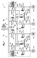
- Fig. 1 shows a vehicle brake system with which various safety functions can be performed.
- a conventional vehicle brake system 1 comprises a master cylinder 2, a dash-dotted line fluid control unit 3 and four wheel brakes 4.1, to 4.4, each having an associated wheel brake cylinder, not shown.
- two of the four wheel brakes 4.1 to 4.4 are associated with a brake circuit 10, 20, wherein each brake circuit 10, 20 is connected to the master cylinder 2.
- a first wheel brake 4.1 which is arranged for example on a vehicle rear axle on the left side
- a second wheel 4.2 which is arranged for example on a vehicle front axle on the right side, associated with a first brake circuit 10
- a third wheel brake 4.3 is arranged for example on the vehicle front axle on the right side
- a fourth wheel 4.4 which is arranged for example on a vehicle rear axle on the left side, are associated with a second brake circuit 20.
- Each wheel brake 4.1 to 4.4 is associated with an inlet valve 13.1, 13.2, 23.1, 23.2 and an outlet valve 14.1, 14.2, 24.1, 24.2, wherein via the inlet valves 13.1, 13.2, 23.1, 23.2 each pressure in the corresponding wheel brake 4.1, can be built up to 4.4, and wherein via the exhaust valves 14.1, 14.2, 24.1, 24.2 each pressure in the corresponding wheel 4.1, 4.4 can be reduced.
- the first brake circuit 10 a first intake valve 11, a first switching valve 12, a first fluid reservoir 16 and a first return pump 15.
- the second brake circuit 20 has a second intake valve 21, a second changeover valve 22, a second fluid reservoir 26 and a second return pump 25, wherein the first and second return pump 15, 25 are driven in the example shown by a common electric motor 35.
- the fluid control unit 3 uses for braking pressure modulation in the first brake circuit 10, the first switching valve 12, the first intake valve 11 and the first return pump 15 and the brake pressure modulation in the second brake circuit 20, the second switching valve 22nd , the second intake valve 21 and the second return pump 25.
- the return pumps 15, 25 of the two brake circuits 10, 20 can be designed, for example, as piston pumps or as gear pumps.
- a brake pressure of up to 140 bar can be set by the open intake valves 11 and 21, with which the suction side of the corresponding return pump 15, 25 is loaded when the system has to be braked. Even in a partially active system state, the return pump 15, 25 can be acted upon suction side with up to 140 bar.
- Fig. 1 how out Fig. 1 can be seen, is to limit the effective pressure on the suction side of the corresponding return pump 15, 25, as in a non-prepublished patent application of the applicant WO 2009/021778 A1 is described, in each case an additional control valve 40, 40 'looped into a suction line between the corresponding return pump 15, 25 and the master cylinder 2, so that the corresponding return pump 15, 25 on the suction side via the control valve 40, 40' or the suction valve 11, 21 with the master cylinder 2 is connected, ie the control valve 40, 40 'is connected in parallel to the intake valve 11,21 and limits the effective pressure on the suction side of the return pump 15 to the predetermined maximum pressure value.
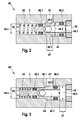
- the control valve 40, 40 ' has a master cylinder connection 41, 41', a pump connection 42, 42 ', a pressure-relieved connection 43, 43' to the atmosphere and a longitudinally movable piston 44.
- the longitudinally movable piston 44 is embodied as a graduated piston 44, which has a first diameter 48.1 for the pressure-relieved connection 43, 43 'and has a second diameter 48.2 to the pump connection 42, 42', the second diameter 48.2 being larger than the first diameter 48.1 is.
- the piston 44 is sealed to the pressure-relieved connection 43, 43 'and to the pump connection 42, 42' in each case via a sealing ring 46.1, 46.2 against the housing.
- a transition of the piston 44 from the first to the second diameter 48.1, 48.2 is designed as a sealing cone 49.1, which corresponds to a sealing seat 49.2 in the housing.
- the longitudinally movable piston 44 is acted upon at the pressure-relieved side by a spring 45 with a spring force and remains in a non-pressurized state in a starting position, the Fig. 2 is shown, in which a via a piston bore 44.1 existing fluid connection between the master brake cylinder port 41 and the pump port 42 is completely released.
- the piston 44 is acted upon by a side of the master brake cylinder port 41, which moves the piston 44 against the spring force of the spring 45 in the direction of the pressure-relieved connection 43 '.
- the in Fig. 3 Upon reaching the maximum pressure value and the corresponding stop position, the in Fig. 3 is shown seals the sealing cone 49.1 of the piston 44 in the sealing seat 49.2 of the housing, and the connection between the master brake cylinder port 41 'and the pump port 42' is completely interrupted by the piston 44. Thereby, the inflow from the master cylinder 2 to the return pump 25 is inhibited and the fluid control unit 3 can perform an ABS control in this state.
- the piston 44 of the control valve 40, 40 'from the side of the master cylinder connection 41, 41' is acted upon by a pressure which moves the piston 44 against the spring force of the spring 45 in the direction of the pressure-relieved connection 43, 43 ', wherein the fluid communication between the master brake cylinder port 41, 41 'and the pump port 42, 42' is reduced by the piston movement.
- the piston 44 Upon reaching the maximum pressure value, the piston 44 is in the corresponding stop position, the in Fig. 3 is shown, in which the connection between the master brake cylinder port 41 'and the pump port 42' is completely interrupted by the piston 44. As a result, a further pressure build-up to the return pump 25 is prevented.
- control valve 40, 40 ' is the diameter 48.1 of the piston 44, which is moved over the upcoming control pressure against the return spring 45 in the closing direction, smaller than the diameter 48.2 of the sealing seat 49.1, which receives the sealing cone 49.2. Therefore, the control pressure for actuating the control valve 40, 40 'should be relatively high, wherein the friction of the sealing elements can lead to increased hysteresis of the closing pressure.
- the documents DE 42 02 388 A1 . EP 0 606 840 A1 . WO 98/00323 A1 and WO 93/19960 each disclose a hydraulic brake system for motor vehicles.
- the disclosed hydraulic brake system includes a control valve having a first fluid port, a second fluid port and a pressure-relieved port to the atmosphere. Furthermore, a longitudinally movable control piston is acted upon by a spring with a spring force on the pressure-relieved side and, in an initial position, provides a fluid connection between the first fluid connection and the second fluid connection completely free.
- a valve body with a sealing seat and a sealing element coupled to the control piston are provided, wherein a sealing region of the sealing element cooperates with the sealing seat of the valve body in order to limit an effective pressure at the second fluid connection to a predefinable maximum pressure value.
- an effective diameter of the control piston is made greater than or equal to an effective diameter of the sealing element, wherein the control piston is coupled by a pin to the sealing element.
- the control piston and the sealing element are arranged on different sides of the valve body, and the pin is guided through a flow opening of the valve body.
- the control valve according to the invention for a vehicle brake system with the features of independent claim 1 has the advantage that it has a valve body with a sealing seat and a coupled with a control piston sealing element.
- a sealing region of the sealing element cooperates with the sealing seat of the valve body to limit an effective pressure at a second fluid port to a predeterminable maximum pressure value, wherein an effective diameter of the control piston is greater than or equal to an effective diameter of the sealing element, to the control performance of the control valve to improve or to reduce a required control pressure for actuating the control valve.
- the control valve according to the invention has a first fluid connection, a second fluid connection and a pressure-relieved connection to the atmosphere, wherein the longitudinally movable control piston is acted upon by a spring with a spring force on the pressure-relieved side and in a starting position a fluid connection between the first fluid connection and the second fluid connection completely releases.
- the control valve according to the invention can advantageously take over the function of an intake valve in the vehicle brake system and can additionally protect a return pump from elevated admission pressure on the suction side.
- control piston is coupled by a pin to the sealing element, wherein the control piston and the sealing element are arranged on different sides of the valve body, and the pin is guided through a flow opening of the valve body.
- the sealing element can for example be plugged onto the pin and be sealed at the rear region via a sealing lip on the pin.
- the sealing element at the front sealing region has a radial range of motion to the pin.
- the pin is connected at one end to the control piston, which is sealed by a first seal against a first valve wall, and has at the other end a collar on which a second seal is applied, which via a on Sealing member supporting spring element is axially biased and seals the pin against a second valve wall.
- the seal on the pin should be as low-friction as possible in order to avoid excessive hysteresis. This is achieved by the axial bias of the second seal by the spring element. This can be avoided in an advantageous manner, a radial bias of the seal, which could lead to a basic friction in the unpressurized state.
- the seal can seal pressure when applied a higher pressure.
- a pressure building up on the first fluid connection moves the control piston against the spring force of the positioning spring in the direction of the pressure-relieved connection, wherein the fluid connection between the first fluid connection and the second fluid connection is advantageously achieved by the movement of the sealing element coupled to the control piston can be reduced.
- the fluid connection between the first fluid port and the second fluid port is completely interrupted at the predetermined maximum pressure value at the second fluid port by a stop position of the sealing region of the sealing element in the sealing seat of the valve body, and the spring force of the actuating spring moves the control piston from the stop position back toward the starting position, if at the second fluid port, the current pressure drops below the maximum pressure value.
- the first fluid port is designed, for example, as a master brake cylinder port, which is coupled to a master brake cylinder in the vehicle brake system
- the second fluid port is designed, for example, as a pump port, which is coupled to a return pump.
- An inventive vehicle brake system with the features of claim 6 comprises a master cylinder, a fluid control unit and at least one wheel brake, the fluid control unit for brake pressure modulation of at least one wheel brake in at least one brake circuit each comprise a switching valve, a suction valve and a return pump.
- the intake valve of the at least one brake circuit is designed as a control valve described above according to the invention, which is looped in each case in a suction line between the corresponding return pump and the master cylinder.
- the control valve according to the invention in the vehicle brake system advantageously takes over the function of the intake valve and protects the remindfiihrungspumpe in addition to increased admission pressure on the suction side.
- control piston of the control valve during a suction operation of the return pump remains in the starting position, and is acted upon during a partially active state of the vehicle brake system from the master cylinder connection with a pressure which moves the control piston against the spring force of the spring in the direction of the pressure-relieved terminal.
- the piston Upon reaching the maximum pressure value and the corresponding stop position, in which the sealing region of the sealing element coupled to the control piston seals in the sealing seat of the valve body, the piston completely interrupts the fluid connection between the master brake cylinder connection and the pump connection.
- the spring force of the adjusting spring moves the control piston from the stop position back to the starting position when the current pressure at the pump connection drops below the maximum pressure value.
- the control piston of the control valve remains in the pressureless state in the starting position, and is during a ABS engagement of the master brake cylinder port is subjected to a pressure that moves the spool against the spring force of the spring in the direction of the pressure-relieved port.
- the control piston Upon reaching the maximum pressure value and the corresponding stop position, in which the sealing region of the sealing element coupled to the control piston seals in the sealing seat of the valve body, the control piston completely interrupts the fluid connection between the master brake cylinder connection and the pump connection, the fluid control unit performing an ABS control in this state ,
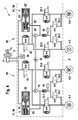
- FIG. 4 illustrated embodiment of a vehicle brake system 1 ' is substantially the same as the conventional vehicle brake system 1 according to Fig. 1 constructed and includes except a first control valve 50 and a second control valve 50 ', the same components that perform the same or analog functions.
- the embodiment of the vehicle brake system 1 ' comprises a master cylinder 2, a dash-dotted fluid control unit 3' and four wheel brakes 4.1, to 4.4, each having an associated wheel brake cylinder, not shown.
- Each two of the four wheel brakes 4.1 to 4.4 are associated with a brake circuit 10 ', 20', wherein each brake circuit 10 ', 20' is connected to the master cylinder 2.
- a first wheel brake 4.1 which is arranged for example on a vehicle rear axle on the left side
- a second wheel brake 4.2 which is arranged for example on a vehicle front axle on the right side
- a first brake circuit 10 'associated with and a third wheel 4.3, which is arranged for example on the vehicle front axle on the right side
- a fourth wheel 4.4 which is arranged for example on a vehicle rear axle on the left side, are associated with a second brake circuit 20 '.
- Each wheel brake 4.1 to 4.4 is associated with an inlet valve 13.1, 13.2, 23.1, 23.2 and an outlet valve 14.1, 14.2, 24.1, 24.2, wherein via the inlet valves 13.1, 13.2, 23.1, 23.2 each pressure in the corresponding Wheel brake 4.1, can be built up to 4.4, and wherein via the exhaust valves 14.1, 14.2, 24.1, 24.2 each pressure in the corresponding wheel 4.1, 4.4 can be reduced.
- the first wheel brake 4.1 is assigned a first inlet valve 13.1 and a first outlet valve 14.1; the second wheel brake 4.2 is assigned a second inlet valve 13.2 and a second outlet valve 14.2.
- the third wheel brake 4.3 are associated with a third inlet valve 23.1 and a third outlet valve 24.2 and the fourth wheel 4.4 are associated with a fourth inlet valve 23.1 and a fourth outlet valve 24.1.
- the first brake circuit 10 has a first intake valve 11', a first switching valve 12, a first fluid reservoir 16 and a first return pump 15.
- the second brake circuit 20 ' has a second intake valve 21', a second changeover valve 22, a second fluid accumulator 26 and a second return pump 25.
- the return pumps 15, 25 of the two brake circuits 10 ', 20' can be designed for example as piston pumps or as gear pumps and are driven in the illustrated embodiment by a common electric motor 35. Furthermore, the fluid control unit 3 'uses a sensor unit 30 to determine the current brake pressure. The fluid control unit 3' uses the first switching valve 12, the first intake valve 11 'and the first return pump 15 and the brake pressure modulation in the second brake circuit 20 for brake pressure modulation in the first brake circuit 10''the second switching valve 22, the second intake valve 21' and the second return pump 25th
- the intake valves 11 ', 21' are designed as control valves 50, 50 ', which are each looped in a suction line between the corresponding return pump 15, 25 and the master cylinder 2.
- the control valves 50, 50 ' are described below with reference to FIG Fig. 5 and 6 described.
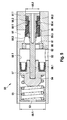
- the first control valve 50 in Fig. 4 and 5 shown in the open initial state during a suction operation of the first return pump 15, and the second control valve 50 'is in Fig. 4 and 6 shown in the closed state.
- control valves 50, 50 'each have a master cylinder connection 51, 51', a pump port 52, 52 'and a pressure-relieved port 53, 53' to the atmosphere.
- control valves 50, 50 'each comprise a valve body 60 with a sealing seat 61 and one with a control piston 54 coupled sealing element 59.
- a sealing region 59.2 of the sealing element 59 cooperates with the sealing seat 61 of the valve body 60 to limit an effective pressure at the pump port 52, 52 'to a predetermined maximum pressure value.
- valve body 60 is caulked to a Verstemm Siemens 62 with a valve wall, and an effective diameter 58.1 of the control piston 54 is greater than an effective diameter 58.2 of the sealing member 59 executed.
- the longitudinally movable control piston 54 is acted upon at the pressure-relieved side by a spring 55 with a spring force and are in the in Fig. 5 illustrated starting position a fluid connection between the master brake cylinder port 51 and the pump port 52 completely free.
- the control piston 54 is coupled by a pin 57 with the sealing element 59, wherein the control piston 54 and the sealing element 59 are arranged on different sides of the valve body 60, ie the control piston 54 is arranged in the illustrated embodiment, left of the valve body 60, and the sealing element 59 is arranged in the illustrated embodiment, right of the valve body 60.
- the pin 57 is guided for coupling the control piston 54 with the sealing element 59 through a flow opening of the valve body 60.
- the sealing element 59 is plugged onto the pin 57 and is sealed at the rear region via a sealing lip 59.1, for example made of plastic, on the pin 57.
- the sealing element 59 has a radial movement clearance 59.3 to the pin 57 to compensate for manufacturing tolerances and to ensure a safe closing of the control valve.
- the pin 57 is latched at one end via locking lugs in a blind bore in the control piston 54 and so firmly connected to the control piston 54, which is sealed by a first sealing ring 56.1 against a first valve wall 50.1.
- the pin 57 can be pressed at one end into the blind bore in the control piston 54 and so firmly connected to the control piston 54.
- the pin 57 has a collar 57.1, against which a second sealing ring 56.2 abuts, which is axially biased by a spring element 59.4 supported on the sealing element 59 and seals the pin 57 against a second valve wall 50.2.
- the first diameter 58.1 of the control piston 54 is forced from the side of the master brake cylinder port 51, 51 'with a pressure of approximately 2 bar acted upon, the control piston 54 moves against the spring force of the spring 55 in the direction of the pressure-relieved terminal 53, 53 'and pulls over the pin 57, the sealing member 59 with the second diameter 58.2, until the designed as a sealing cone sealing area 59.2 of the sealing element 59 in one in Fig. 6 shown stop position on the sealing seat 61 of the valve body 60 is applied.
- the piston 54 of the control valve 50 is pressurized from the side of the master brake cylinder port 51, which moves the piston 54 against the spring force of the spring 55 in the direction of the pressure-relieved port 53, wherein the fluid connection between the master brake cylinder port 51st and the pump port 52 is reduced by the corresponding movement of the sealing member 59.
- the piston 54 is in the corresponding stop position, the in Fig. 6 is shown, in which the connection between the master brake cylinder port 51 'and the pump port 52' is completely interrupted by the sealing element 59.
- control valve according to the invention thereby enables the diameter of the control piston to be made greater than or equal to the diameter of the sealing element, that the control quality can be improved or the control pressure for actuating the control valve can be reduced.
- control valve according to the invention in the vehicle brake system can take over the task of the intake valve and can additionally protect the return pump against elevated pressure on the suction side.
Landscapes
- Engineering & Computer Science (AREA)
- Physics & Mathematics (AREA)
- Fluid Mechanics (AREA)
- Mechanical Engineering (AREA)
- General Engineering & Computer Science (AREA)
- Transportation (AREA)
- Regulating Braking Force (AREA)
- Valves And Accessory Devices For Braking Systems (AREA)
Claims (8)
- Soupape de régulation pour un système de freinage de véhicule comprenant un premier raccord de fluide (51, 51'), un deuxième raccord de fluide (52, 52') et un raccord (53, 53') détendu en pression vers l'atmosphère, un piston de commande (54) déplaçable longitudinalement étant sollicité, au niveau du côté détendu en pression, par une force de ressort d'un ressort de réglage (55) et, dans une position de départ, libérant entièrement une liaison fluidique entre le premier raccord de fluide (51, 51') et le deuxième raccord de fluide (52, 52'), un corps de soupape (60) pourvu d'un siège d'étanchéité (61) et un élément d'étanchéité (59) accouplé au piston de commande (54) étant prévus, une zone d'étanchéité avant (59.2) de l'élément d'étanchéité (59) coopérant avec le siège d'étanchéité (61) du corps de soupape (60), afin de limiter une pression effective au niveau du deuxième raccord de fluide (52, 52') à une valeur de pression maximale pouvant être prédéfinie, un diamètre effectif (58.1) du piston de commande (54) étant réalisé plus grand que, ou égal à, un diamètre effectif (58.2) de l'élément d'étanchéité (59), le piston de commande (54) étant accouplé à l'élément d'étanchéité (59) au moyen d'une goupille (57), et le piston de commande (54) et l'élément d'étanchéité (59) étant disposés sur des côtés différents du corps de soupape (60), et la goupille (57) étant guidée à travers une ouverture de passage du corps de soupape (60), caractérisée en ce que l'élément d'étanchéité (59) présente, sur la zone d'étanchéité avant (59.2), un jeu de déplacement radial (59.3) par rapport à la goupille (57).
- Soupape de régulation selon la revendication 1, caractérisée en ce que l'élément d'étanchéité (59) est enfoncé sur la goupille (57) et, au niveau de la zone arrière, réalise l'étanchéité sur la goupille (57) par le biais d'une lèvre d'étanchéité (59.1).
- Soupape de régulation selon la revendication 1 ou 2, caractérisée en ce que la goupille (57) est reliée au piston de commande (54) à une extrémité, lequel piston de commande réalise l'étanchéité contre une première paroi de soupape (50.1) par le biais d'un premier joint d'étanchéité (56.1), et présente, à l'autre extrémité, un épaulement (57.1) contre lequel s'applique un deuxième élément d'étanchéité (56.2) qui est précontraint axialement par le biais d'un élément ressort (59.4) s'appuyant contre l'élément d'étanchéité (59) et réalise l'étanchéité de la goupille (57) contre une deuxième paroi de soupape (50.2).
- Soupape de régulation selon l'une quelconque des revendications 1 à 3, caractérisée en ce qu'une pression augmentant au niveau du premier raccord de fluide (51, 51') déplace le piston de commande (54) à l'encontre de la force de ressort du ressort de réglage (55) en direction du raccord détendu en pression (53, 53'), la liaison fluidique entre le premier raccord de fluide (51, 51') et le deuxième raccord de fluide (52, 52') pouvant être réduite par le déplacement de l'élément d'étanchéité (59) accouplé au piston de commande (57), la liaison fluidique entre le premier raccord de fluide (51, 51') et le deuxième raccord de fluide (52, 52') étant, en cas de valeur de pression maximale prédéfinie au niveau du deuxième raccord de fluide (52, 52'), entièrement interrompue par une position de butée de la zone d'étanchéité (59.2) de l'élément d'étanchéité (59) dans le siège d'étanchéité (61) du corps de soupape (60), et la force de ressort du ressort de réglage (55) déplaçant le piston de commande (54) hors de la position de butée à nouveau en direction de la position de départ lorsque la pression instantanée au niveau du deuxième raccord de fluide (52, 52') descend en dessous de la valeur de pression maximale.
- Soupape de régulation selon l'une quelconque des revendications 1 à 4, caractérisée en ce que le premier raccord de fluide est réalisé sous forme de raccord de maître-cylindre de frein (51, 51'), lequel peut être accouplé avec un maître-cylindre de frein (2) dans le système de freinage de véhicule (1'), et le deuxième raccord de fluide est réalisé sous forme de raccord de pompe (52, 52') qui peut être accouplé avec une pompe de retour (15, 25).
- Système de freinage de véhicule comprenant un maître-cylindre de frein (2), une unité de commande de fluide (3') et au moins un frein de roue (4.1 à 4.4), l'unité de commande de fluide (3') comportant, pour la modulation de la pression de freinage de l'au moins un frein de roue (4.1 à 4.4) dans au moins un circuit de freinage (10', 20'), respectivement une soupape d'inversion (12, 22), une soupape d'aspiration (11', 21') et une pompe de retour (15, 25), caractérisé en ce que la soupape d'aspiration (11', 21') est réalisée sous forme de soupape de régulation (50, 50') selon l'une quelconque des revendications 1 à 5, laquelle est respectivement insérée dans une conduite d'aspiration entre la pompe de retour (15, 25) correspondante et le maître-cylindre de frein (2).
- Système de freinage selon la revendication 6, caractérisé en ce que le piston de commande (54) de la soupape de régulation (50, 50') demeure dans la position de départ pendant le fonctionnement d'aspiration de la pompe de retour (15, 25) et est, pendant un état partiellement actif du système de freinage, sollicité par le raccord de maître-cylindre de frein (51, 51') avec une pression qui déplace le piston de commande (54) à l'encontre de la force de ressort du ressort de réglage (55) en direction du raccord (53) détendu en pression, le piston (54), à l'obtention de la valeur de pression maximale et de la position de butée correspondante, dans laquelle la zone d'étanchéité (59.2) de l'élément d'étanchéité (59) accouplé au piston de commande (54) réalise l'étanchéité dans le siège d'étanchéité (61) du corps de soupape (60), interrompant entièrement la liaison fluidique entre le raccord de maître-cylindre de frein (51, 51') et le raccord de pompe (52, 52'), et la force de ressort du ressort de réglage (55) déplaçant le piston de commande (54) hors de la position de butée en direction de la position de départ lorsque la pression instantanée au niveau du raccord de pompe (52, 52') descend en dessous de la valeur de pression maximale.
- Système de freinage selon la revendication 6 ou 7, caractérisé en ce que le piston de commande (54) de la soupape de régulation (50, 50') demeure dans la position de départ dans l'état non sollicité en pression, et pendant un engagement d'ABS par le raccord de maître-cylindre de frein (51, 51'), est sollicité avec une pression qui déplace le piston de commande (54) à l'encontre de la force de ressort du ressort de réglage (55) en direction du raccord détendu en pression (53, 53'), le piston de commande (54), à l'obtention de la valeur de pression maximale et de la position de butée correspondante, dans laquelle la zone d'étanchéité (59.2) de l'élément d'étanchéité (59) accouplé au piston de commande (54) réalise l'étanchéité dans le siège d'étanchéité (61) du corps de soupape (60), interrompant entièrement la liaison fluidique entre le raccord de maître-cylindre de frein (51, 51') et le raccord de pompe (52, 52'), l'unité de commande de fluide (3') effectuant dans cet état une régulation d'ABS.
Applications Claiming Priority (2)
| Application Number | Priority Date | Filing Date | Title |
|---|---|---|---|
| DE102008002539A DE102008002539A1 (de) | 2008-06-19 | 2008-06-19 | Regelventil für ein Fahrzeugbremssystem und korrespondierendes Fahrzeugbremssystem |
| PCT/EP2009/054648 WO2009153081A1 (fr) | 2008-06-19 | 2009-04-20 | Soupape de réglage pour un système de freinage de véhicule et système de freinage de véhicule avec une soupape de ce type |
Publications (2)
| Publication Number | Publication Date |
|---|---|
| EP2303652A1 EP2303652A1 (fr) | 2011-04-06 |
| EP2303652B1 true EP2303652B1 (fr) | 2014-09-03 |
Family
ID=40834327
Family Applications (1)
| Application Number | Title | Priority Date | Filing Date |
|---|---|---|---|
| EP09765661.5A Not-in-force EP2303652B1 (fr) | 2008-06-19 | 2009-04-20 | Soupape de réglage pour un système de freinage de véhicule et système de freinage de véhicule avec une soupape de ce type |
Country Status (6)
| Country | Link |
|---|---|
| US (1) | US20110101772A1 (fr) |
| EP (1) | EP2303652B1 (fr) |
| JP (1) | JP5328901B2 (fr) |
| CN (1) | CN102066169B (fr) |
| DE (1) | DE102008002539A1 (fr) |
| WO (1) | WO2009153081A1 (fr) |
Families Citing this family (17)
| Publication number | Priority date | Publication date | Assignee | Title |
|---|---|---|---|---|
| DE102011085881A1 (de) * | 2011-11-08 | 2013-05-08 | Robert Bosch Gmbh | Hydraulisch betätigtes Regelventil für ein Fahrzeugbremssystem und zugehöriges Fahrzeugbremssystem |
| ITMO20120087A1 (it) * | 2012-04-02 | 2013-10-03 | Atlantic Fluid Tech S R L | Valvola di sostentamento carico |
| DE102013222346A1 (de) | 2013-11-04 | 2015-05-07 | Robert Bosch Gmbh | Druckmittelventil |
| DE102013224067B4 (de) | 2013-11-26 | 2026-02-19 | Robert Bosch Gmbh | Bremssystem für ein Fahrzeug |
| DE102013224980A1 (de) | 2013-12-05 | 2015-06-11 | Robert Bosch Gmbh | Druckbegrenzungsventil |
| DE102014224597A1 (de) | 2014-12-02 | 2016-06-02 | Robert Bosch Gmbh | Druckmittelventil |
| KR101536096B1 (ko) * | 2015-01-26 | 2015-07-10 | 김성민 | 브레이크 압력증폭장치 |
| FR3037029B1 (fr) * | 2015-06-05 | 2017-07-14 | Faiveley Transp Amiens | Systeme de freinage ferroviaire pour vehicule ferroviaire |
| US10793133B2 (en) * | 2016-07-01 | 2020-10-06 | Borgwarner Inc. | Valve assembly and system including same for controlling fluid flow to and from a clutch |
| DE102016216347A1 (de) * | 2016-08-30 | 2018-03-01 | Robert Bosch Gmbh | Ventilanker und Ventilpatrone für ein Magnetventil |
| CN106627542B (zh) * | 2016-11-16 | 2023-05-02 | 眉山中车制动科技股份有限公司 | 一种多通路橡胶圆柱密封分配阀 |
| CN108571609B (zh) * | 2017-03-10 | 2022-12-23 | 艾默生过程管理调节技术公司 | 用于内阀的弹簧座 |
| CN109958806B (zh) * | 2019-03-22 | 2020-04-10 | 桂林航天工业学院 | 一种气动汽车用气动动力控制装置 |
| US12311402B2 (en) * | 2019-06-18 | 2025-05-27 | Panasonic Intellectual Property Management Co., Ltd. | Intermittent valve and intermittent coating apparatus |
| IT202000028418A1 (it) * | 2020-11-25 | 2022-05-25 | Raicam Driveline S R L | Unità valvolare per un sistema di frenatura antibloccaggio |
| EP4454962B1 (fr) * | 2023-04-28 | 2025-11-19 | ZF CV Systems Global GmbH | Soupape, système pneumatique et véhicule, en particulier véhicule utilitaire |
| CN116498755B (zh) * | 2023-06-27 | 2023-08-29 | 中北大学 | 一种超临界二氧化碳压差控制式快速开关阀 |
Family Cites Families (12)
| Publication number | Priority date | Publication date | Assignee | Title |
|---|---|---|---|---|
| US2899976A (en) * | 1959-08-18 | Release relief valve | ||
| DE4202388A1 (de) * | 1992-01-29 | 1993-08-05 | Bosch Gmbh Robert | Hydraulische bremsanlage mit blockierschutz- und antriebsschlupf-regeleinrichtung, insbesondere fuer kraftfahrzeuge |
| DE4236045A1 (de) * | 1992-04-03 | 1993-11-04 | Teves Gmbh Alfred | Hydraulisches umschaltventil fuer eine fahrzeugbremsanlage |
| JPH0655909U (ja) | 1993-01-14 | 1994-08-02 | 住友電気工業株式会社 | ブレーキ液圧制御装置 |
| JP3246366B2 (ja) * | 1996-03-29 | 2002-01-15 | 住友電気工業株式会社 | ブレーキ液圧制御装置 |
| DE19626289B4 (de) | 1996-07-01 | 2008-08-14 | Continental Teves Ag & Co. Ohg | Hydraulische Bremsanlage mit einer Rückförderpumpe |
| US5996966A (en) * | 1998-04-02 | 1999-12-07 | Tri-Clover, Inc. | Snap-on valve gasket |
| DE50207312D1 (de) * | 2001-06-30 | 2006-08-03 | Bosch Gmbh Robert | Kolbenpumpe |
| DE102006025027A1 (de) * | 2006-05-26 | 2007-11-29 | Robert Bosch Gmbh | Kolbenpumpe |
| DE102007038397A1 (de) | 2007-08-14 | 2009-02-19 | Robert Bosch Gmbh | Bremssystem für ein Fahrzeug |
| DE102007052664A1 (de) * | 2007-11-05 | 2009-05-07 | Robert Bosch Gmbh | Führungsring für eine Kolbenpumpe sowie Kolbenpumpe |
| JP5080521B2 (ja) * | 2009-03-24 | 2012-11-21 | 日立オートモティブシステムズ株式会社 | ブレーキ装置 |
-
2008
- 2008-06-19 DE DE102008002539A patent/DE102008002539A1/de not_active Withdrawn
-
2009
- 2009-04-20 WO PCT/EP2009/054648 patent/WO2009153081A1/fr not_active Ceased
- 2009-04-20 EP EP09765661.5A patent/EP2303652B1/fr not_active Not-in-force
- 2009-04-20 US US12/737,202 patent/US20110101772A1/en not_active Abandoned
- 2009-04-20 CN CN200980122740.XA patent/CN102066169B/zh not_active Expired - Fee Related
- 2009-04-20 JP JP2011513962A patent/JP5328901B2/ja not_active Expired - Fee Related
Also Published As
| Publication number | Publication date |
|---|---|
| CN102066169B (zh) | 2014-06-11 |
| DE102008002539A1 (de) | 2009-12-24 |
| CN102066169A (zh) | 2011-05-18 |
| JP5328901B2 (ja) | 2013-10-30 |
| US20110101772A1 (en) | 2011-05-05 |
| EP2303652A1 (fr) | 2011-04-06 |
| JP2011524301A (ja) | 2011-09-01 |
| WO2009153081A1 (fr) | 2009-12-23 |
Similar Documents
| Publication | Publication Date | Title |
|---|---|---|
| EP2303652B1 (fr) | Soupape de réglage pour un système de freinage de véhicule et système de freinage de véhicule avec une soupape de ce type | |
| EP2178727B1 (fr) | Système de freinage pour un véhicule | |
| EP0807038B1 (fr) | Vanne electromagnetique pourvue d'une fonction de limitation de pression dans un systeme de freinage hydraulique d'automobile a anti-patinage et/ou enclenchement automatique des freins pour la regulation de la dynamique de route | |
| DE69927928T2 (de) | Bremssystem | |
| EP2205865B1 (fr) | Pompe à piston destinée au refoulement d'un fluide et système de freinage associé | |
| EP1894803A2 (fr) | Elément d'étanchéité pour un cylindre de frein d'une installation de frein de véhicule | |
| WO2012097963A1 (fr) | Dispositif d'actionnement, procédé permettant de faire fonctionner un dispositif d'actionnement et ensemble d'électrovannes | |
| EP3526087B1 (fr) | Électrovanne et système de freinage hydraulique pour véhicule | |
| EP2427355B1 (fr) | Unité d'actionnement de frein pour l'actionnement d'un système de freinage de véhicule automobile | |
| DE102015218263A1 (de) | Magnetventil | |
| EP0477523A2 (fr) | Soupape de limitation de pression, notamment pour systèmes hydrauliques de freinage de véhicules automobiles | |
| DE102009027706A1 (de) | Regelventil für ein Fahrzeugbremssystem und korrespondierendes Fahrzeugbremssystem | |
| DE102006013626A1 (de) | Elektrohydraulische Bremsanlage mit Fahrdynamikregelung | |
| EP3795436B1 (fr) | Modulateur de pression pour un système antiblocage d'un vélo | |
| DE102019216715A1 (de) | Zweistufiges Magnetventil | |
| EP2852783A1 (fr) | Dispositif à soupape pour circuit hydraulique et dispositif de commande d'une pompe à huile | |
| EP2018303A1 (fr) | Dispositif de freinage hydraulique | |
| WO1998041430A1 (fr) | Systeme de freinage hydraulique commande par une force exterieure | |
| WO2008058801A1 (fr) | Pompe à piston pour un système de freinage de véhicule | |
| EP2086805A1 (fr) | Pompe à piston | |
| EP1322510A1 (fr) | Servofrein pneumatique a rapport de demultiplication de force variable | |
| DE3812832C1 (fr) | ||
| EP3177493B1 (fr) | Seromoteur pneumatique d'assistance au freinage | |
| DE102013224067B4 (de) | Bremssystem für ein Fahrzeug | |
| DE102004056661A1 (de) | Elektronisch regelbare Fahrzeugbremsanlage |
Legal Events
| Date | Code | Title | Description |
|---|---|---|---|
| PUAI | Public reference made under article 153(3) epc to a published international application that has entered the european phase |
Free format text: ORIGINAL CODE: 0009012 |
|
| 17P | Request for examination filed |
Effective date: 20110119 |
|
| AK | Designated contracting states |
Kind code of ref document: A1 Designated state(s): AT BE BG CH CY CZ DE DK EE ES FI FR GB GR HR HU IE IS IT LI LT LU LV MC MK MT NL NO PL PT RO SE SI SK TR |
|
| AX | Request for extension of the european patent |
Extension state: AL BA RS |
|
| DAX | Request for extension of the european patent (deleted) | ||
| GRAP | Despatch of communication of intention to grant a patent |
Free format text: ORIGINAL CODE: EPIDOSNIGR1 |
|
| INTG | Intention to grant announced |
Effective date: 20140606 |
|
| GRAS | Grant fee paid |
Free format text: ORIGINAL CODE: EPIDOSNIGR3 |
|
| GRAA | (expected) grant |
Free format text: ORIGINAL CODE: 0009210 |
|
| AK | Designated contracting states |
Kind code of ref document: B1 Designated state(s): AT BE BG CH CY CZ DE DK EE ES FI FR GB GR HR HU IE IS IT LI LT LU LV MC MK MT NL NO PL PT RO SE SI SK TR |
|
| REG | Reference to a national code |
Ref country code: GB Ref legal event code: FG4D Free format text: NOT ENGLISH |
|
| REG | Reference to a national code |
Ref country code: CH Ref legal event code: EP Ref country code: AT Ref legal event code: REF Ref document number: 685408 Country of ref document: AT Kind code of ref document: T Effective date: 20140915 |
|
| REG | Reference to a national code |
Ref country code: IE Ref legal event code: FG4D Free format text: LANGUAGE OF EP DOCUMENT: GERMAN |
|
| REG | Reference to a national code |
Ref country code: DE Ref legal event code: R096 Ref document number: 502009009901 Country of ref document: DE Effective date: 20141016 |
|
| PG25 | Lapsed in a contracting state [announced via postgrant information from national office to epo] |
Ref country code: GR Free format text: LAPSE BECAUSE OF FAILURE TO SUBMIT A TRANSLATION OF THE DESCRIPTION OR TO PAY THE FEE WITHIN THE PRESCRIBED TIME-LIMIT Effective date: 20141204 Ref country code: ES Free format text: LAPSE BECAUSE OF FAILURE TO SUBMIT A TRANSLATION OF THE DESCRIPTION OR TO PAY THE FEE WITHIN THE PRESCRIBED TIME-LIMIT Effective date: 20140903 Ref country code: NO Free format text: LAPSE BECAUSE OF FAILURE TO SUBMIT A TRANSLATION OF THE DESCRIPTION OR TO PAY THE FEE WITHIN THE PRESCRIBED TIME-LIMIT Effective date: 20141203 Ref country code: LT Free format text: LAPSE BECAUSE OF FAILURE TO SUBMIT A TRANSLATION OF THE DESCRIPTION OR TO PAY THE FEE WITHIN THE PRESCRIBED TIME-LIMIT Effective date: 20140903 Ref country code: FI Free format text: LAPSE BECAUSE OF FAILURE TO SUBMIT A TRANSLATION OF THE DESCRIPTION OR TO PAY THE FEE WITHIN THE PRESCRIBED TIME-LIMIT Effective date: 20140903 Ref country code: SE Free format text: LAPSE BECAUSE OF FAILURE TO SUBMIT A TRANSLATION OF THE DESCRIPTION OR TO PAY THE FEE WITHIN THE PRESCRIBED TIME-LIMIT Effective date: 20140903 |
|
| REG | Reference to a national code |
Ref country code: NL Ref legal event code: VDEP Effective date: 20140903 |
|
| REG | Reference to a national code |
Ref country code: LT Ref legal event code: MG4D |
|
| PG25 | Lapsed in a contracting state [announced via postgrant information from national office to epo] |
Ref country code: HR Free format text: LAPSE BECAUSE OF FAILURE TO SUBMIT A TRANSLATION OF THE DESCRIPTION OR TO PAY THE FEE WITHIN THE PRESCRIBED TIME-LIMIT Effective date: 20140903 Ref country code: CY Free format text: LAPSE BECAUSE OF FAILURE TO SUBMIT A TRANSLATION OF THE DESCRIPTION OR TO PAY THE FEE WITHIN THE PRESCRIBED TIME-LIMIT Effective date: 20140903 Ref country code: LV Free format text: LAPSE BECAUSE OF FAILURE TO SUBMIT A TRANSLATION OF THE DESCRIPTION OR TO PAY THE FEE WITHIN THE PRESCRIBED TIME-LIMIT Effective date: 20140903 |
|
| PG25 | Lapsed in a contracting state [announced via postgrant information from national office to epo] |
Ref country code: NL Free format text: LAPSE BECAUSE OF FAILURE TO SUBMIT A TRANSLATION OF THE DESCRIPTION OR TO PAY THE FEE WITHIN THE PRESCRIBED TIME-LIMIT Effective date: 20140903 |
|
| PG25 | Lapsed in a contracting state [announced via postgrant information from national office to epo] |
Ref country code: IS Free format text: LAPSE BECAUSE OF FAILURE TO SUBMIT A TRANSLATION OF THE DESCRIPTION OR TO PAY THE FEE WITHIN THE PRESCRIBED TIME-LIMIT Effective date: 20150103 Ref country code: CZ Free format text: LAPSE BECAUSE OF FAILURE TO SUBMIT A TRANSLATION OF THE DESCRIPTION OR TO PAY THE FEE WITHIN THE PRESCRIBED TIME-LIMIT Effective date: 20140903 Ref country code: RO Free format text: LAPSE BECAUSE OF FAILURE TO SUBMIT A TRANSLATION OF THE DESCRIPTION OR TO PAY THE FEE WITHIN THE PRESCRIBED TIME-LIMIT Effective date: 20140903 Ref country code: EE Free format text: LAPSE BECAUSE OF FAILURE TO SUBMIT A TRANSLATION OF THE DESCRIPTION OR TO PAY THE FEE WITHIN THE PRESCRIBED TIME-LIMIT Effective date: 20140903 Ref country code: PT Free format text: LAPSE BECAUSE OF FAILURE TO SUBMIT A TRANSLATION OF THE DESCRIPTION OR TO PAY THE FEE WITHIN THE PRESCRIBED TIME-LIMIT Effective date: 20150105 Ref country code: SK Free format text: LAPSE BECAUSE OF FAILURE TO SUBMIT A TRANSLATION OF THE DESCRIPTION OR TO PAY THE FEE WITHIN THE PRESCRIBED TIME-LIMIT Effective date: 20140903 |
|
| PG25 | Lapsed in a contracting state [announced via postgrant information from national office to epo] |
Ref country code: PL Free format text: LAPSE BECAUSE OF FAILURE TO SUBMIT A TRANSLATION OF THE DESCRIPTION OR TO PAY THE FEE WITHIN THE PRESCRIBED TIME-LIMIT Effective date: 20140903 |
|
| REG | Reference to a national code |
Ref country code: DE Ref legal event code: R097 Ref document number: 502009009901 Country of ref document: DE |
|
| PLBE | No opposition filed within time limit |
Free format text: ORIGINAL CODE: 0009261 |
|
| STAA | Information on the status of an ep patent application or granted ep patent |
Free format text: STATUS: NO OPPOSITION FILED WITHIN TIME LIMIT |
|
| PG25 | Lapsed in a contracting state [announced via postgrant information from national office to epo] |
Ref country code: DK Free format text: LAPSE BECAUSE OF FAILURE TO SUBMIT A TRANSLATION OF THE DESCRIPTION OR TO PAY THE FEE WITHIN THE PRESCRIBED TIME-LIMIT Effective date: 20140903 |
|
| 26N | No opposition filed |
Effective date: 20150604 |
|
| PG25 | Lapsed in a contracting state [announced via postgrant information from national office to epo] |
Ref country code: IT Free format text: LAPSE BECAUSE OF FAILURE TO SUBMIT A TRANSLATION OF THE DESCRIPTION OR TO PAY THE FEE WITHIN THE PRESCRIBED TIME-LIMIT Effective date: 20140903 |
|
| PG25 | Lapsed in a contracting state [announced via postgrant information from national office to epo] |
Ref country code: LU Free format text: LAPSE BECAUSE OF FAILURE TO SUBMIT A TRANSLATION OF THE DESCRIPTION OR TO PAY THE FEE WITHIN THE PRESCRIBED TIME-LIMIT Effective date: 20150420 Ref country code: SI Free format text: LAPSE BECAUSE OF FAILURE TO SUBMIT A TRANSLATION OF THE DESCRIPTION OR TO PAY THE FEE WITHIN THE PRESCRIBED TIME-LIMIT Effective date: 20140903 Ref country code: MC Free format text: LAPSE BECAUSE OF FAILURE TO SUBMIT A TRANSLATION OF THE DESCRIPTION OR TO PAY THE FEE WITHIN THE PRESCRIBED TIME-LIMIT Effective date: 20140903 |
|
| REG | Reference to a national code |
Ref country code: CH Ref legal event code: PL |
|
| GBPC | Gb: european patent ceased through non-payment of renewal fee |
Effective date: 20150420 |
|
| REG | Reference to a national code |
Ref country code: IE Ref legal event code: MM4A |
|
| PG25 | Lapsed in a contracting state [announced via postgrant information from national office to epo] |
Ref country code: LI Free format text: LAPSE BECAUSE OF NON-PAYMENT OF DUE FEES Effective date: 20150430 Ref country code: CH Free format text: LAPSE BECAUSE OF NON-PAYMENT OF DUE FEES Effective date: 20150430 Ref country code: GB Free format text: LAPSE BECAUSE OF NON-PAYMENT OF DUE FEES Effective date: 20150420 |
|
| REG | Reference to a national code |
Ref country code: FR Ref legal event code: ST Effective date: 20151231 |
|
| PG25 | Lapsed in a contracting state [announced via postgrant information from national office to epo] |
Ref country code: FR Free format text: LAPSE BECAUSE OF NON-PAYMENT OF DUE FEES Effective date: 20150430 |
|
| PG25 | Lapsed in a contracting state [announced via postgrant information from national office to epo] |
Ref country code: IE Free format text: LAPSE BECAUSE OF NON-PAYMENT OF DUE FEES Effective date: 20150420 |
|
| REG | Reference to a national code |
Ref country code: AT Ref legal event code: MM01 Ref document number: 685408 Country of ref document: AT Kind code of ref document: T Effective date: 20150420 |
|
| PG25 | Lapsed in a contracting state [announced via postgrant information from national office to epo] |
Ref country code: AT Free format text: LAPSE BECAUSE OF NON-PAYMENT OF DUE FEES Effective date: 20150420 |
|
| PG25 | Lapsed in a contracting state [announced via postgrant information from national office to epo] |
Ref country code: MT Free format text: LAPSE BECAUSE OF FAILURE TO SUBMIT A TRANSLATION OF THE DESCRIPTION OR TO PAY THE FEE WITHIN THE PRESCRIBED TIME-LIMIT Effective date: 20140903 |
|
| PG25 | Lapsed in a contracting state [announced via postgrant information from national office to epo] |
Ref country code: HU Free format text: LAPSE BECAUSE OF FAILURE TO SUBMIT A TRANSLATION OF THE DESCRIPTION OR TO PAY THE FEE WITHIN THE PRESCRIBED TIME-LIMIT; INVALID AB INITIO Effective date: 20090420 Ref country code: BG Free format text: LAPSE BECAUSE OF FAILURE TO SUBMIT A TRANSLATION OF THE DESCRIPTION OR TO PAY THE FEE WITHIN THE PRESCRIBED TIME-LIMIT Effective date: 20140903 |
|
| PG25 | Lapsed in a contracting state [announced via postgrant information from national office to epo] |
Ref country code: BE Free format text: LAPSE BECAUSE OF NON-PAYMENT OF DUE FEES Effective date: 20150430 |
|
| PG25 | Lapsed in a contracting state [announced via postgrant information from national office to epo] |
Ref country code: TR Free format text: LAPSE BECAUSE OF FAILURE TO SUBMIT A TRANSLATION OF THE DESCRIPTION OR TO PAY THE FEE WITHIN THE PRESCRIBED TIME-LIMIT Effective date: 20140903 |
|
| PG25 | Lapsed in a contracting state [announced via postgrant information from national office to epo] |
Ref country code: MK Free format text: LAPSE BECAUSE OF FAILURE TO SUBMIT A TRANSLATION OF THE DESCRIPTION OR TO PAY THE FEE WITHIN THE PRESCRIBED TIME-LIMIT Effective date: 20140903 |
|
| REG | Reference to a national code |
Ref country code: DE Ref legal event code: R084 Ref document number: 502009009901 Country of ref document: DE |
|
| PGFP | Annual fee paid to national office [announced via postgrant information from national office to epo] |
Ref country code: DE Payment date: 20230627 Year of fee payment: 15 |
|
| REG | Reference to a national code |
Ref country code: DE Ref legal event code: R119 Ref document number: 502009009901 Country of ref document: DE |
|
| PG25 | Lapsed in a contracting state [announced via postgrant information from national office to epo] |
Ref country code: DE Free format text: LAPSE BECAUSE OF NON-PAYMENT OF DUE FEES Effective date: 20241105 |
|
| PG25 | Lapsed in a contracting state [announced via postgrant information from national office to epo] |
Ref country code: DE Free format text: LAPSE BECAUSE OF NON-PAYMENT OF DUE FEES Effective date: 20241105 |