EP2292674B1 - Elément de mousse doté d'au moins deux structures géométriques différentiables - Google Patents
Elément de mousse doté d'au moins deux structures géométriques différentiables Download PDFInfo
- Publication number
- EP2292674B1 EP2292674B1 EP10007930.0A EP10007930A EP2292674B1 EP 2292674 B1 EP2292674 B1 EP 2292674B1 EP 10007930 A EP10007930 A EP 10007930A EP 2292674 B1 EP2292674 B1 EP 2292674B1
- Authority
- EP
- European Patent Office
- Prior art keywords
- foam
- moulded
- foam element
- element according
- molded foam
- Prior art date
- Legal status (The legal status is an assumption and is not a legal conclusion. Google has not performed a legal analysis and makes no representation as to the accuracy of the status listed.)
- Active
Links
Images

Classifications
-
- E—FIXED CONSTRUCTIONS
- E04—BUILDING
- E04B—GENERAL BUILDING CONSTRUCTIONS; WALLS, e.g. PARTITIONS; ROOFS; FLOORS; CEILINGS; INSULATION OR OTHER PROTECTION OF BUILDINGS
- E04B1/00—Constructions in general; Structures which are not restricted either to walls, e.g. partitions, or floors or ceilings or roofs
- E04B1/62—Insulation or other protection; Elements or use of specified material therefor
- E04B1/92—Protection against other undesired influences or dangers
- E04B1/94—Protection against other undesired influences or dangers against fire
- E04B1/941—Building elements specially adapted therefor
- E04B1/943—Building elements specially adapted therefor elongated
-
- C—CHEMISTRY; METALLURGY
- C08—ORGANIC MACROMOLECULAR COMPOUNDS; THEIR PREPARATION OR CHEMICAL WORKING-UP; COMPOSITIONS BASED THEREON
- C08G—MACROMOLECULAR COMPOUNDS OBTAINED OTHERWISE THAN BY REACTIONS ONLY INVOLVING UNSATURATED CARBON-TO-CARBON BONDS
- C08G18/00—Polymeric products of isocyanates or isothiocyanates
- C08G18/06—Polymeric products of isocyanates or isothiocyanates with compounds having active hydrogen
- C08G18/08—Processes
-
- B—PERFORMING OPERATIONS; TRANSPORTING
- B29—WORKING OF PLASTICS; WORKING OF SUBSTANCES IN A PLASTIC STATE IN GENERAL
- B29C—SHAPING OR JOINING OF PLASTICS; SHAPING OF MATERIAL IN A PLASTIC STATE, NOT OTHERWISE PROVIDED FOR; AFTER-TREATMENT OF THE SHAPED PRODUCTS, e.g. REPAIRING
- B29C44/00—Shaping by internal pressure generated in the material, e.g. swelling or foaming ; Producing porous or cellular expanded plastics articles
- B29C44/34—Auxiliary operations
- B29C44/35—Component parts; Details or accessories
- B29C44/352—Means for giving the foam different characteristics in different directions
-
- B—PERFORMING OPERATIONS; TRANSPORTING
- B29—WORKING OF PLASTICS; WORKING OF SUBSTANCES IN A PLASTIC STATE IN GENERAL
- B29K—INDEXING SCHEME ASSOCIATED WITH SUBCLASSES B29B, B29C OR B29D, RELATING TO MOULDING MATERIALS OR TO MATERIALS FOR MOULDS, REINFORCEMENTS, FILLERS OR PREFORMED PARTS, e.g. INSERTS
- B29K2075/00—Use of PU, i.e. polyureas or polyurethanes or derivatives thereof, as moulding material
-
- C—CHEMISTRY; METALLURGY
- C08—ORGANIC MACROMOLECULAR COMPOUNDS; THEIR PREPARATION OR CHEMICAL WORKING-UP; COMPOSITIONS BASED THEREON
- C08G—MACROMOLECULAR COMPOUNDS OBTAINED OTHERWISE THAN BY REACTIONS ONLY INVOLVING UNSATURATED CARBON-TO-CARBON BONDS
- C08G2110/00—Foam properties
- C08G2110/0025—Foam properties rigid
-
- C—CHEMISTRY; METALLURGY
- C08—ORGANIC MACROMOLECULAR COMPOUNDS; THEIR PREPARATION OR CHEMICAL WORKING-UP; COMPOSITIONS BASED THEREON
- C08G—MACROMOLECULAR COMPOUNDS OBTAINED OTHERWISE THAN BY REACTIONS ONLY INVOLVING UNSATURATED CARBON-TO-CARBON BONDS
- C08G2110/00—Foam properties
- C08G2110/0041—Foam properties having specified density
- C08G2110/005—< 50kg/m3
-
- C—CHEMISTRY; METALLURGY
- C08—ORGANIC MACROMOLECULAR COMPOUNDS; THEIR PREPARATION OR CHEMICAL WORKING-UP; COMPOSITIONS BASED THEREON
- C08G—MACROMOLECULAR COMPOUNDS OBTAINED OTHERWISE THAN BY REACTIONS ONLY INVOLVING UNSATURATED CARBON-TO-CARBON BONDS
- C08G2115/00—Oligomerisation
- C08G2115/02—Oligomerisation to isocyanurate groups
-
- E—FIXED CONSTRUCTIONS
- E04—BUILDING
- E04B—GENERAL BUILDING CONSTRUCTIONS; WALLS, e.g. PARTITIONS; ROOFS; FLOORS; CEILINGS; INSULATION OR OTHER PROTECTION OF BUILDINGS
- E04B1/00—Constructions in general; Structures which are not restricted either to walls, e.g. partitions, or floors or ceilings or roofs
- E04B1/62—Insulation or other protection; Elements or use of specified material therefor
- E04B1/74—Heat, sound or noise insulation, absorption, or reflection; Other building methods affording favourable thermal or acoustical conditions, e.g. accumulating of heat within walls
- E04B1/76—Heat, sound or noise insulation, absorption, or reflection; Other building methods affording favourable thermal or acoustical conditions, e.g. accumulating of heat within walls specifically with respect to heat only
- E04B1/762—Exterior insulation of exterior walls
Definitions
- PUR foam Polyurethane foams
- PIR foam polyisocyanurate foams
- EP 1 571 167 A2 a sandwich element in which an isocyanate-based rigid foam is foamed between two metallic or flexible cover layers by means of a double-band process.
- these PUR / PIR rigid foams have a more advantageous thermal conductivity and thus a higher insulation performance. In thermal insulation composite systems, especially for the insulation of buildings, however, these are problematic.
- the invention has for its object to provide an inexpensive molded foam element. It is solved according to the invention by the features of claim 1. Further refinements result from the subclaims.
- a molded foam element is at least essentially, ie more than 50%, and particularly preferably completely made of polyurethane foam (PUR foam) and / or polyisocyanurate foam (PIR foam), which has been produced in a continuous process and has a homogeneous bulk density between 28 and has 40 kg / m 3 , in particular for thermal insulation composite systems (ETICS) on buildings, with a cell structure that at least has two mutually perpendicular spatial structures which are distinguishable from one another and which film-free design is proposed.
- PUR foam polyurethane foam
- PIR foam polyisocyanurate foam
- a foam element that is anisotropic in terms of its properties can be realized, which means that a Molded foam element can be easily opened up a variety of uses. This can simplify the production of molded foam elements, such as for thermal insulation composite systems or fire protection bars, which can reduce costs.
- a “cell structure” is to be understood in particular to mean a geometric structure of the polyurethane foam (PUR foam) and / or of the polyisocyanurate foam. In particular, this is to be understood to mean a geometric structure of individual gas cells within the PUR / PIR foam.
- the cell structure can be determined using microscopic means.
- the cell structure which is defined by the gas cells within the polyurethane, is comparable to an ellipsoidal structure, ie the gas cells which are arranged as gas inclusions in the PUR / PIR foam have an ellipsoidal shape on average.
- the gas cells thus each form a geometric structure along the spatial directions, the mean geometric properties of which can be distinguished.
- a “geometry structure” is to be understood in particular to mean an average geometric dimension of the gas cells along the corresponding spatial direction.
- An “average geometric dimension” is to be understood in particular to mean an average value of a distribution, the distribution advantageously being designed as a size distribution of dimensions of the gas cells along the corresponding spatial direction.
- distinguishable geometry structures is to be understood in particular that the mean values of the dimensions of the gas cells for the different spatial directions by at least 5%, advantageously by at least 10% and particularly preferably by at least 20% differ from each other.
- a “spatial direction” should be understood to mean one of three spatial directions perpendicular to one another.
- the cell structure have distinct compressive stresses assigned to the individual spatial directions. This enables a particularly simple adaptation of the properties of the molded element.
- “distinguishable compressive stresses” should in particular be understood to mean that values of the compressive stresses along the spatial directions differ from one another by at least 5%, advantageously by at least 10% and particularly preferably by at least 20%.
- the cell structure has distinguishable compressive strengths assigned to the individual spatial directions.
- the molded foam element can advantageously be provided for applications in composite thermal insulation systems.
- a “compressive strength” is to be understood in particular to mean a compressive strength in accordance with DIN 53421.
- “distinguishable compressive strengths” is to be understood in particular to mean that values of the compressive strengths differ from one another by at least 5%, advantageously by at least 10% and particularly preferably by at least 20%.
- the compressive strengths of all spatial directions are preferably at least 0.10 N / mm 2 .
- the cell structure have a geometry structure oriented in a third spatial direction that is distinguishable from the other two geometry structures.
- This allows the molded foam element to be used in a particularly varied manner.
- Such an embodiment differentiates the cell structure from the egg-shaped cell structure in particular in that it is rotationally asymmetrical with respect to the spatial direction along which the geometry structure with the largest dimension is oriented.
- One of the geometry structures is preferably oriented along a foaming direction.
- the geometry structure with the largest dimension is preferably oriented along the foaming direction.
- a “foaming direction” is understood to mean in particular a direction along which the PUR / PIR foam foams after being applied to a belt system.
- the molded foam element has a bulk density that is between 28 and 40 kg / m 3 .
- a "bulk density”, specified in kg / m 3 is to be understood in particular to mean a density of a material, the determination of which includes a pore volume in a material volume.
- the bulk density of the molded foam element is homogeneous.
- a "homogeneous" bulk density should be used can be understood in particular that in a distribution of measured values of the bulk density, which is determined on sample volumes in the form of cubes with an edge length of ten millimeters, that consists of part of the molded foam element from a central plane lying parallel to an outer surface through a center of volume up to outer surface, at least 70% of the determined measured values of the bulk density lie in an interval of ⁇ 20%, in particular in an interval of ⁇ 10%, around a statistical mean.
- the "center of volume” should in particular be understood as identical to a center of gravity of the fire protection bolt element with a bulk density assumed to be constant.
- the molded foam element has a coefficient of thermal conductivity, the calculated value of which is at most 0.028 W / (m • K). This enables particularly efficient thermal insulation to be achieved.
- a “calculated value” is to be understood in particular to mean a value corrected by an aging standard parameter.
- a “calculated value” is to be understood to mean a value which has been corrected according to DIN EN 13165 by an aging standard parameter which depends on a thickness of the thermal insulation board.
- the calculated value of the coefficient of thermal conductivity for thin molded foam elements is preferably at most 0.028 W / (m • K), whereby thin molded foam elements are to be understood to mean plates whose thickness is less than 80 mm.
- the calculated value of the coefficient of thermal conductivity for medium-sized molded foam elements is preferably at most 0.027 W / (m • K), wherein "medium-sized molded foam elements" are to be understood as sheets whose Thickness is at least 80 mm and is less than 120 mm.
- the calculated value of the coefficient of thermal conductivity for thick molded foam elements is advantageously not more than 0.027 W / (m • K), whereby thick molded foam elements are to be understood to mean plates whose thickness is at least 120 mm.
- a further 0.001 can be subtracted from the calculated values of the thermal conductivity figures, which results in a calculated value of 0.027 W / (m • K) for thin molded foam elements, a calculated value of 0.026 W / (m • K) and a calculation value of 0.025 W / (m • K) results for thick molded foam elements.
- the molded foam element has at least one partial surface area to which a coating is applied.
- a surface of the molded foam element can advantageously be adapted to different requirements.
- a “coating” is to be understood to mean the application of an informal material, in particular in contrast to the application of a layer of a material with a shape, to the outer surface, in particular by a spraying or brushing method, depending on the person skilled in the art of the material used, common methods are known.
- the molded foam element is thereby designed to be film-free, a “film” being understood to mean in particular a thin-layered element, that is to say in particular an element less than five millimeters thick, in particular an element which is also connected without a carrier material.
- the coating is particularly advantageously applied to the molded foam element for the purpose of a color design and / or for fastening without intermediate supports, which enables a particularly simple construction of fire protection.
- Plaster structures can advantageously be applied directly to the molded foam element, as a result of which exterior facades of buildings with molded foam elements can be created in a particularly simple manner.
- the coating is preferably provided to protect against UV radiation. This can prevent degradation of the properties of the fire protection bolt element and in particular of its near-surface material during a construction phase in which the molded foam element can be exposed to UV radiation.
- the coating is provided to reduce dust formation. In particular, this can reduce a load during processing.
- a “reduction in the formation of dust” is to be understood here in particular to mean that a dust released by the molded foam element is reduced.
- the molded foam element is particularly preferably dust-free, i.e. there is no dust.
- a method for producing a thermal insulation element from a molded foam element according to the invention in which the molded foam element is cut in such a way that a normal of the surface extension of the thermal insulation element is directed along a production direction.
- a compressive strength can easily be provided, through which sufficient dimensional stability can be achieved to avoid warping.
- a production direction should in particular be understood to mean a direction along which the molded foam element is applied to a belt system for foaming.
- a method for producing a fire protection bolt element from a molded foam element according to the invention is proposed, the molded foam element being cut in such a way that a normal of the surface extension of the fire protection bolt element is directed along a foaming direction.
- a compressive strength can also be provided in a simple manner for the fire protection bolt element, which also forms a molded foam element according to the invention, by means of which sufficient dimensional stability can be achieved to avoid warping.
- a “foaming direction” is to be understood in particular to mean a direction along which the molded foam element expands on a belt system during foaming. In particular, this is to be understood to mean a direction that is oriented perpendicular to a surface extension of the belt system.
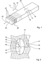
- FIGS 1 to 3 schematically show a molded foam element made of a polyurethane foam (PUR foam) or a polyisocyanurate foam (PIR foam), which was produced according to a foaming process known to those skilled in the art.
- PUR foam polyurethane foam
- PIR foam polyisocyanurate foam
- a degree of anisotropy of the PUR / PIR foam can be set by means of the additives, some of which act as catalysts for the foaming process, an inclination angle of the belt system and a production speed.
- the catalysis controls a reaction rate with which the components of the PUR / PIR foam react with each other.
- the catalysis is defined by the additives.
- the molded foam element has a cell structure 13 which forms three distinguishable geometry structures 14, 15, 16.
- the geometric structures 14, 15, 16 are oriented along the three perpendicular spatial directions 10, 11, 12.
- the different geometry structures 14, 15, 16 cause different compressive stresses for the three spatial directions 10, 11, 12 of the molded foam element.
- the different compressive stresses in turn result in the molded foam element being able to withstand different loads in the different spatial directions 10, 11, 12.
- the load capacity can be determined by means of suitable measurement methods known to the person skilled in the art.
- the person skilled in the art can also determine the different geometry structures 14, 15, 16 in the three spatial directions 10, 11, 12 directly by means of microscopic analysis.
- a load capacity resulting from the compressive stresses according to DIN 53421 is at least 10 N / mm 2 in each of the spatial directions 10, 11, 12.
- the load capacity along the first spatial direction 10 is approximately 0.14-0.20 N / mm 2 .
- the load capacity along the second spatial direction 11 is approximately 0.11-0.14 N / mm 2 .
- the load capacity along the third spatial direction 12 is approximately 0.10-0.11 N / mm 2 .
- the three spatial directions 10, 11, 12 can be defined by means of a production direction 18, which is determined by applying the PUR / PIR foam to the belt system.
- the production direction 18 corresponds to a direction in which the belt system is moved.
- the continuously applied molded foam element has a main extension 25, which is directed along the production direction 18.
- the conveyor system forms a production area to which the PUR / PIR foam is applied.
- the PUR / PIR foam applied to the conveyor system foams vertically to the production area after application.
- a direction perpendicular to the production area is thus defined as a foaming direction 17.
- a direction parallel to the production area and perpendicular to the production direction 18 or perpendicular to the foaming direction 17 is defined as a transverse direction 19.
- the foaming direction 17, the production direction 18 and the transverse direction 19 correspond to the three perpendicular spatial directions 10, 11, 12.
- the first spatial direction 10 is defined parallel to the foaming direction 17.
- the second spatial direction 11 is parallel to the production direction 18 defined.
- the third spatial direction 12 is defined parallel to the transverse direction 19.
- the three different geometry structures 14, 15, 16 are designed as geometry properties, which are defined by different dimensions of the cell structure 13 along the spatial directions 10, 11, 12.
- the cell structure 13 comprises gas cells which are arranged within the polyurethane or polyisocyanurate.
- the dimensions that form the geometric structures 14, 15, 16 describe a spatial size of the gas cells. Individual gas cells can have different dimensions.
- the geometric structures 14, 15, 16 are each formed by an average value of a size distribution, which the dimension of the gas cells has along the assigned spatial direction 10, 11, 12.
- the size distribution is determined within a unit volume, such as within a cube with an edge length of 1 cm.
- the geometry structure 14, which is oriented along the first spatial direction 10, corresponds to the largest dimension within the cell structure 13. It is therefore assigned the highest load capacity.
- the geometry structure 16, which is oriented along the third spatial direction 12, has the smallest dimension within the cell structure 13. It is therefore assigned the lowest resilience.
- the geometry structure 15, which is oriented along the second spatial direction 11, has a dimension that is greater than that of the geometry structure 16 and smaller than that of the geometry structure 14.
- the geometry structures 14, 15, 16 each differ by at least 20%. Values of the geometry structures can be determined directly using the load capacities specified above.
- the molded foam element made from the PUR / PIR foam has a bulk density that is between 28 and 40 kg / m 3 .
- a PIR foam for example, which has a homogeneous bulk density, is used to form fire protection bolt elements 23 by means of the molded foam element.
- the bulk density is 32 kg / m 3 .
- Each fire protection bolt element 23 is designed in a shape which essentially corresponds to a prismatic body, namely in particular a cuboid. Its rectangular cross-sectional shape has a height dimension of 220 mm and a material thickness of 160 mm.
- Molded foam elements 26 cut from the molded foam element which are designed, for example, as thermal insulation elements 21 or fire protection locking elements 23, have a coefficient of thermal conductivity whose calculated value, depending on a standardized thickness of the cut molded foam elements 26, is less than 0.026 W / (m • K) to 0.028 W / (m • K) is.
- the coefficient of thermal conductivity is, for example, 0.026 W / (m • K).
- the cut molded foam elements 26 have partial surface areas to which a coating 20 is applied.
- the coating 20 is designed to protect UV radiation. It has at least one component that at least largely absorbs UV radiation, in particular UV-A radiation and UV-B radiation. Means of the UV coating, the cut molded foam elements 26 are protected in particular against natural UV radiation from the sun. An entire surface of the molded foam elements 26 is coated with the coating.
- the coating 20 is provided to reduce dust formation.
- the coating 20 encloses the PUR / PIR foam of the molded foam elements 26.
- the PUR / PIR foam is thereby bound within the coating 20, as a result of which dust formation by the PUR / PIR foam is suppressed. Since the coating 20 completely encloses the molded foam elements 26, the cut and coated molded foam elements 26 are dust-free.
- the continuously produced, unprocessed molded foam element has a main direction of extension 25 which is directed along the production direction 18.
- the molded foam element is first cut to a rectangular cross section.
- the preprocessed molded foam element is then present as a cuboid, the main direction of extension 25 of which is directed along the production direction 18.
- the now cuboid shaped foam element has an extension which is smaller than the remaining extensions of the preprocessed molded foam element.
- the preprocessed molded foam element has an average extension along the transverse direction 19.
- the pre-processed molded foam element can be assembled for different types of application by a further cut.
- molded foam elements 26 are obtained which can be used as the thermal insulation elements 21 for thermal insulation composite systems on buildings.
- the molded foam elements 26 cut along the planes defined by the spatial directions 10, 12 have surface extensions along the two spatial directions 10, 12.
- a normal 22 of the surface extension is thus oriented along the production direction 18.
- a thickness of the molded foam elements 26, which is determined along the normal 22 of the surface extension, is thereby oriented along the second spatial direction 11 (cf. Figure 1 ).
- molded foam elements 26 are obtained which can be used as fire protection bolt elements 23 on buildings.
- the shaped foam elements 26 cut in this way have a surface extension along the plane defined by the spatial directions 11, 12.
- a normal 24 of the surface extension is thus oriented along the foaming direction 17.
- a thickness of the molded foam elements 26, which is determined along the normal 24 of the surface extension, is thereby oriented along the first spatial direction 10 (cf. Figure 3 ).
Landscapes
- Chemical & Material Sciences (AREA)
- Engineering & Computer Science (AREA)
- Architecture (AREA)
- Health & Medical Sciences (AREA)
- Civil Engineering (AREA)
- Structural Engineering (AREA)
- Physics & Mathematics (AREA)
- Electromagnetism (AREA)
- Chemical Kinetics & Catalysis (AREA)
- Medicinal Chemistry (AREA)
- Polymers & Plastics (AREA)
- Organic Chemistry (AREA)
- Building Environments (AREA)
- Polyurethanes Or Polyureas (AREA)
Claims (11)
- Élément en mousse moulée composé de mousse de polyuréthane (mousse PUR) et/ou de mousse de polyisocyanurate (mousse PIR) produite dans un procédé continu et ayant une densité apparente homogène entre 28 kg/m3 et 40 kg/m3, en particulier pour des systèmes composites d'isolation thermique (ITE/ETICS) aux immeubles,
avec une structure cellulaire (13) qui comporte des structures géométriques différenciables (14, 15, 16) dans au moins deux directions spatiales (10, 11, 12) orientées perpendiculairement l'une par rapport à l'autre, et qui est réalisée sans film. - Élément en mousse moulée selon la revendication 1,
caractérisé en ce que
la structure cellulaire (13) présente des tensions compressives différenciables allouées aux directions spatiales individuelles (10, 11, 12). - Élément en mousse moulée selon la revendication 1 ou 2,
caractérisé en ce que
la structure cellulaire (13) présente des résistances à compression différenciables allouées aux directions spatiales individuelles (10, 11, 12). - Élément en mousse moulée selon l'une quelconque des revendications précédentes,
caractérisé en ce que
la structure cellulaire (13) présente une structure géométrique (16) qui est orientée dans une troisième direction spatiale (12) et est différenciable des deux autres structures géométriques (14, 15). - Élément en mousse moulée selon l'une quelconque des revendications précédentes,
caractérisé en ce que
l'une des structures géométriques (14) et orientée le long d'une direction de moussage (17). - Élément en mousse moulée selon l'une quelconque des revendications précédentes,
caractérisé par
une conductivité thermique la valeur de calcul de laquelle est maximalement 0,028 W/m∗K), la valeur de calcul étant une valeur corrigée selon DIN EN 13165 par un paramètre standard de vieillissement qui dépend d'une épaisseur de la plaque d'isolation thermique. - Élément en mousse moulée selon l'une quelconque des revendications précédentes,
caractérisé par
au moins une zone partielle de superficie, sur laquelle un revêtement (20) a été appliqué. - Élément en mousse moulée selon la revendication 7,
caractérisé en ce que
le revêtement (20) est prévu pour une protection contre rayonnement UV. - Élément en mousse moulée selon la revendication 7 ou 8,
caractérisé en ce que
le revêtement (20) est prévu pour une réduction d'une formation de poussière. - Procédé pour la production d'au moins un élément d'isolation thermique (21) d'un élément en mousse moulée selon l'une quelconque des revendications précédentes,
caractérisé en ce que
l'élément en mousse moulée est coupé à mesure de telle manière qu'une normale (22) d'une étendue planaire de l'élément d'isolation thermique (21) est orientée le long d'une direction de production (18). - Procédé pour la production d'un élément de verrou ignifuge (23) d'un élément en mousse moulée selon les revendications 1 à 9,
caractérisé en ce que
l'élément en mousse moulée est coupé à mesure de telle manière qu'une normale (24) d'une étendue planaire de l'élément de verrou ignifuge (23) est orientée le long d'une direction de moussage (17).
Applications Claiming Priority (1)
| Application Number | Priority Date | Filing Date | Title |
|---|---|---|---|
| DE102009040203A DE102009040203A1 (de) | 2009-09-07 | 2009-09-07 | Formschaumelement mit zumindest zwei unterscheidbaren Geometriestrukturen |
Publications (3)
| Publication Number | Publication Date |
|---|---|
| EP2292674A2 EP2292674A2 (fr) | 2011-03-09 |
| EP2292674A3 EP2292674A3 (fr) | 2013-02-20 |
| EP2292674B1 true EP2292674B1 (fr) | 2020-07-29 |
Family
ID=43234266
Family Applications (1)
| Application Number | Title | Priority Date | Filing Date |
|---|---|---|---|
| EP10007930.0A Active EP2292674B1 (fr) | 2009-09-07 | 2010-07-29 | Elément de mousse doté d'au moins deux structures géométriques différentiables |
Country Status (2)
| Country | Link |
|---|---|
| EP (1) | EP2292674B1 (fr) |
| DE (1) | DE102009040203A1 (fr) |
Families Citing this family (3)
| Publication number | Priority date | Publication date | Assignee | Title |
|---|---|---|---|---|
| EP2653287A1 (fr) * | 2012-04-20 | 2013-10-23 | URSA Insulation, S.A. | Panneau isolant et procédé de fabrication le-même |
| EP2845959B1 (fr) | 2013-09-04 | 2017-03-01 | Daw Se | Système composite d'isolation thermique avec élément pare-feu ou pare-feu et utilisation d'un tel système pour l'inhibition de la propagation du feu entre étages |
| EP3023556B1 (fr) | 2014-11-19 | 2018-02-28 | Daw Se | Élément pare-feu et pare-feu constitué d'éléments pare-feu |
Family Cites Families (9)
| Publication number | Priority date | Publication date | Assignee | Title |
|---|---|---|---|---|
| DE4208759A1 (de) * | 1992-03-19 | 1993-09-23 | Basf Ag | Schaumstoffplatten mit verbesserten waermedaemmeigenschaften und verfahren zu ihrer herstellung |
| CZ163699A3 (cs) * | 1996-11-08 | 1999-08-11 | Huntsman Ici Chemicals, Llc | Nové pružné polyurethanové pěny |
| US20030225172A1 (en) * | 2002-05-31 | 2003-12-04 | Miller Larry M. | To enhance the thermal insulation of polymeric foam by reducing cell anisotropic ratio and the method for production thereof |
| US20040157945A1 (en) * | 2002-12-30 | 2004-08-12 | Barber Thomas Allan | Rigid urethane foams |
| DE102004011346A1 (de) * | 2004-03-05 | 2005-09-22 | Basf Ag | Verfahren zur Herstellung von Hartschaumstoffen auf Isocyanatbasis |
| GB0415629D0 (en) * | 2004-07-13 | 2004-08-18 | Leuven K U Res & Dev | Novel protective helmet |
| DE102004041143A1 (de) * | 2004-08-24 | 2006-03-02 | Basf Ag | Katalysatorsystem, insbesondere zur Herstellung von Polyurethanhartschaumstoffen |
| CA2584822A1 (fr) * | 2004-11-12 | 2006-05-18 | Dow Global Technologies Inc. | Elements amortissant les chocs pour applications d'impacts dynamiques |
| JPWO2008069013A1 (ja) * | 2006-12-05 | 2010-03-18 | 株式会社カネカ | エネルギー吸収材に適した樹脂発泡体 |
-
2009
- 2009-09-07 DE DE102009040203A patent/DE102009040203A1/de not_active Ceased
-
2010
- 2010-07-29 EP EP10007930.0A patent/EP2292674B1/fr active Active
Non-Patent Citations (1)
| Title |
|---|
| None * |
Also Published As
| Publication number | Publication date |
|---|---|
| DE102009040203A1 (de) | 2011-03-10 |
| EP2292674A3 (fr) | 2013-02-20 |
| EP2292674A2 (fr) | 2011-03-09 |
Similar Documents
| Publication | Publication Date | Title |
|---|---|---|
| EP1678386B2 (fr) | Nappe de matière isolante en feutre de fibres minérales enroulée sur un rouleau destiné à être bloqué entre poutres | |
| EP2501749B1 (fr) | Mousses de résine contenant des microsphères creuses | |
| EP3938158B1 (fr) | Matériau sous forme de plaque et son procédé de fabrication | |
| EP1749805B1 (fr) | Matériau de construction à base de gypse, ayant une conductivité thermique et un blindage électromagnetique ameliorés. | |
| DE3625534A1 (de) | Bauplatte | |
| WO2012163460A1 (fr) | Module accumulateur d'énergie constitué de plusieurs éléments d'accumulateur notamment en forme de prisme, procédé de production d'un module accumulateur d'énergie et procédé de production d'une plaque d'extrémité pour un module accumulateur d'énergie | |
| DE20307608U1 (de) | Dämmender geschäumter Werkstoff | |
| EP3680509A1 (fr) | Panneau sandwich ayant des propriétés d'amortissement acoustique | |
| EP2292674B1 (fr) | Elément de mousse doté d'au moins deux structures géométriques différentiables | |
| EP0561216B2 (fr) | Plaques de mousse avec des propriétés thermo-isolantes améliorées et méthode pour les fabriquer | |
| EP2147762B1 (fr) | Panneau de plancher d'une plaque de matériau bois et procédé de fabrication | |
| DE102009046257A1 (de) | Plattenförmige Isolationslage für eine Wand, Verfahren zu deren Herstellung sowie plattenförmiges Wandelement | |
| EP3725481A1 (fr) | Matériau sous forme de plaque et son procédé de fabrication | |
| EP0947638B1 (fr) | Panneau d'isolation pour façades extérieures de maisons | |
| WO2008128733A1 (fr) | Plaque d'isolation de façade pour l'isolation de façades externes de bâtiments, système composite d'isolation thermique comportant des plaques d'isolation de façade de ce type et procédé de fabrication d'une plaque d'isolation de façade | |
| DE102007018209A1 (de) | Dämmplatte | |
| AT526148B1 (de) | Holzverbundelement und Verfahren zu dessen Herstellung | |
| EP3603971A1 (fr) | Composant, élément mural pour un bâtiment et procédé de fabrication d'un composant | |
| DE202022101604U1 (de) | Inlay für Metalltüren | |
| DE8617998U1 (de) | Plattenförmiges Verbundelement | |
| EP0959190A2 (fr) | Elément d'isolation thermique | |
| DE102012110225A1 (de) | Wärmedämmelement | |
| DE29919919U1 (de) | Feuerhemmende Sandwichplatte | |
| EP2385208B1 (fr) | Cadre en bois pour un vitrage protégé contre la chute | |
| EP1457615A1 (fr) | Elément de paroi avec des sphères de matière polystyrène |
Legal Events
| Date | Code | Title | Description |
|---|---|---|---|
| PUAI | Public reference made under article 153(3) epc to a published international application that has entered the european phase |
Free format text: ORIGINAL CODE: 0009012 |
|
| AK | Designated contracting states |
Kind code of ref document: A2 Designated state(s): AL AT BE BG CH CY CZ DE DK EE ES FI FR GB GR HR HU IE IS IT LI LT LU LV MC MK MT NL NO PL PT RO SE SI SK SM TR |
|
| AX | Request for extension of the european patent |
Extension state: BA ME RS |
|
| PUAL | Search report despatched |
Free format text: ORIGINAL CODE: 0009013 |
|
| AK | Designated contracting states |
Kind code of ref document: A3 Designated state(s): AL AT BE BG CH CY CZ DE DK EE ES FI FR GB GR HR HU IE IS IT LI LT LU LV MC MK MT NL NO PL PT RO SE SI SK SM TR |
|
| AX | Request for extension of the european patent |
Extension state: BA ME RS |
|
| RIC1 | Information provided on ipc code assigned before grant |
Ipc: C08G 18/08 20060101AFI20130111BHEP Ipc: E04B 1/94 20060101ALI20130111BHEP |
|
| 17P | Request for examination filed |
Effective date: 20130819 |
|
| RBV | Designated contracting states (corrected) |
Designated state(s): AL AT BE BG CH CY CZ DE DK EE ES FI FR GB GR HR HU IE IS IT LI LT LU LV MC MK MT NL NO PL PT RO SE SI SK SM TR |
|
| 17Q | First examination report despatched |
Effective date: 20141001 |
|
| STAA | Information on the status of an ep patent application or granted ep patent |
Free format text: STATUS: EXAMINATION IS IN PROGRESS |
|
| GRAP | Despatch of communication of intention to grant a patent |
Free format text: ORIGINAL CODE: EPIDOSNIGR1 |
|
| STAA | Information on the status of an ep patent application or granted ep patent |
Free format text: STATUS: GRANT OF PATENT IS INTENDED |
|
| RIC1 | Information provided on ipc code assigned before grant |
Ipc: B29C 44/34 20060101ALI20200205BHEP Ipc: C08G 101/00 20060101ALN20200205BHEP Ipc: B29K 75/00 20060101ALI20200205BHEP Ipc: E04B 1/94 20060101ALI20200205BHEP Ipc: E04B 1/76 20060101ALI20200205BHEP Ipc: C08G 18/08 20060101AFI20200205BHEP |
|
| INTG | Intention to grant announced |
Effective date: 20200221 |
|
| GRAS | Grant fee paid |
Free format text: ORIGINAL CODE: EPIDOSNIGR3 |
|
| GRAA | (expected) grant |
Free format text: ORIGINAL CODE: 0009210 |
|
| STAA | Information on the status of an ep patent application or granted ep patent |
Free format text: STATUS: THE PATENT HAS BEEN GRANTED |
|
| AK | Designated contracting states |
Kind code of ref document: B1 Designated state(s): AL AT BE BG CH CY CZ DE DK EE ES FI FR GB GR HR HU IE IS IT LI LT LU LV MC MK MT NL NO PL PT RO SE SI SK SM TR |
|
| REG | Reference to a national code |
Ref country code: GB Ref legal event code: FG4D Free format text: NOT ENGLISH |
|
| REG | Reference to a national code |
Ref country code: CH Ref legal event code: EP |
|
| REG | Reference to a national code |
Ref country code: AT Ref legal event code: REF Ref document number: 1295705 Country of ref document: AT Kind code of ref document: T Effective date: 20200815 |
|
| REG | Reference to a national code |
Ref country code: IE Ref legal event code: FG4D Free format text: LANGUAGE OF EP DOCUMENT: GERMAN |
|
| REG | Reference to a national code |
Ref country code: DE Ref legal event code: R096 Ref document number: 502010016710 Country of ref document: DE |
|
| REG | Reference to a national code |
Ref country code: CH Ref legal event code: NV Representative=s name: PATENTANWALTSKANZLEI DAUB, CH |
|
| REG | Reference to a national code |
Ref country code: NL Ref legal event code: FP |
|
| REG | Reference to a national code |
Ref country code: LT Ref legal event code: MG4D |
|
| PG25 | Lapsed in a contracting state [announced via postgrant information from national office to epo] |
Ref country code: NO Free format text: LAPSE BECAUSE OF FAILURE TO SUBMIT A TRANSLATION OF THE DESCRIPTION OR TO PAY THE FEE WITHIN THE PRESCRIBED TIME-LIMIT Effective date: 20201029 Ref country code: BG Free format text: LAPSE BECAUSE OF FAILURE TO SUBMIT A TRANSLATION OF THE DESCRIPTION OR TO PAY THE FEE WITHIN THE PRESCRIBED TIME-LIMIT Effective date: 20201029 Ref country code: ES Free format text: LAPSE BECAUSE OF FAILURE TO SUBMIT A TRANSLATION OF THE DESCRIPTION OR TO PAY THE FEE WITHIN THE PRESCRIBED TIME-LIMIT Effective date: 20200729 Ref country code: PT Free format text: LAPSE BECAUSE OF FAILURE TO SUBMIT A TRANSLATION OF THE DESCRIPTION OR TO PAY THE FEE WITHIN THE PRESCRIBED TIME-LIMIT Effective date: 20201130 Ref country code: SE Free format text: LAPSE BECAUSE OF FAILURE TO SUBMIT A TRANSLATION OF THE DESCRIPTION OR TO PAY THE FEE WITHIN THE PRESCRIBED TIME-LIMIT Effective date: 20200729 Ref country code: GR Free format text: LAPSE BECAUSE OF FAILURE TO SUBMIT A TRANSLATION OF THE DESCRIPTION OR TO PAY THE FEE WITHIN THE PRESCRIBED TIME-LIMIT Effective date: 20201030 Ref country code: FI Free format text: LAPSE BECAUSE OF FAILURE TO SUBMIT A TRANSLATION OF THE DESCRIPTION OR TO PAY THE FEE WITHIN THE PRESCRIBED TIME-LIMIT Effective date: 20200729 Ref country code: HR Free format text: LAPSE BECAUSE OF FAILURE TO SUBMIT A TRANSLATION OF THE DESCRIPTION OR TO PAY THE FEE WITHIN THE PRESCRIBED TIME-LIMIT Effective date: 20200729 Ref country code: LT Free format text: LAPSE BECAUSE OF FAILURE TO SUBMIT A TRANSLATION OF THE DESCRIPTION OR TO PAY THE FEE WITHIN THE PRESCRIBED TIME-LIMIT Effective date: 20200729 |
|
| PG25 | Lapsed in a contracting state [announced via postgrant information from national office to epo] |
Ref country code: IS Free format text: LAPSE BECAUSE OF FAILURE TO SUBMIT A TRANSLATION OF THE DESCRIPTION OR TO PAY THE FEE WITHIN THE PRESCRIBED TIME-LIMIT Effective date: 20201129 Ref country code: LV Free format text: LAPSE BECAUSE OF FAILURE TO SUBMIT A TRANSLATION OF THE DESCRIPTION OR TO PAY THE FEE WITHIN THE PRESCRIBED TIME-LIMIT Effective date: 20200729 Ref country code: PL Free format text: LAPSE BECAUSE OF FAILURE TO SUBMIT A TRANSLATION OF THE DESCRIPTION OR TO PAY THE FEE WITHIN THE PRESCRIBED TIME-LIMIT Effective date: 20200729 |
|
| PG25 | Lapsed in a contracting state [announced via postgrant information from national office to epo] |
Ref country code: EE Free format text: LAPSE BECAUSE OF FAILURE TO SUBMIT A TRANSLATION OF THE DESCRIPTION OR TO PAY THE FEE WITHIN THE PRESCRIBED TIME-LIMIT Effective date: 20200729 Ref country code: DK Free format text: LAPSE BECAUSE OF FAILURE TO SUBMIT A TRANSLATION OF THE DESCRIPTION OR TO PAY THE FEE WITHIN THE PRESCRIBED TIME-LIMIT Effective date: 20200729 Ref country code: RO Free format text: LAPSE BECAUSE OF FAILURE TO SUBMIT A TRANSLATION OF THE DESCRIPTION OR TO PAY THE FEE WITHIN THE PRESCRIBED TIME-LIMIT Effective date: 20200729 Ref country code: SM Free format text: LAPSE BECAUSE OF FAILURE TO SUBMIT A TRANSLATION OF THE DESCRIPTION OR TO PAY THE FEE WITHIN THE PRESCRIBED TIME-LIMIT Effective date: 20200729 Ref country code: MC Free format text: LAPSE BECAUSE OF FAILURE TO SUBMIT A TRANSLATION OF THE DESCRIPTION OR TO PAY THE FEE WITHIN THE PRESCRIBED TIME-LIMIT Effective date: 20200729 |
|
| REG | Reference to a national code |
Ref country code: DE Ref legal event code: R097 Ref document number: 502010016710 Country of ref document: DE |
|
| PG25 | Lapsed in a contracting state [announced via postgrant information from national office to epo] |
Ref country code: AL Free format text: LAPSE BECAUSE OF FAILURE TO SUBMIT A TRANSLATION OF THE DESCRIPTION OR TO PAY THE FEE WITHIN THE PRESCRIBED TIME-LIMIT Effective date: 20200729 |
|
| PLBE | No opposition filed within time limit |
Free format text: ORIGINAL CODE: 0009261 |
|
| STAA | Information on the status of an ep patent application or granted ep patent |
Free format text: STATUS: NO OPPOSITION FILED WITHIN TIME LIMIT |
|
| GBPC | Gb: european patent ceased through non-payment of renewal fee |
Effective date: 20201029 |
|
| PG25 | Lapsed in a contracting state [announced via postgrant information from national office to epo] |
Ref country code: SK Free format text: LAPSE BECAUSE OF FAILURE TO SUBMIT A TRANSLATION OF THE DESCRIPTION OR TO PAY THE FEE WITHIN THE PRESCRIBED TIME-LIMIT Effective date: 20200729 |
|
| 26N | No opposition filed |
Effective date: 20210430 |
|
| PG25 | Lapsed in a contracting state [announced via postgrant information from national office to epo] |
Ref country code: SI Free format text: LAPSE BECAUSE OF FAILURE TO SUBMIT A TRANSLATION OF THE DESCRIPTION OR TO PAY THE FEE WITHIN THE PRESCRIBED TIME-LIMIT Effective date: 20200729 Ref country code: GB Free format text: LAPSE BECAUSE OF NON-PAYMENT OF DUE FEES Effective date: 20201029 Ref country code: IE Free format text: LAPSE BECAUSE OF NON-PAYMENT OF DUE FEES Effective date: 20200729 |
|
| PG25 | Lapsed in a contracting state [announced via postgrant information from national office to epo] |
Ref country code: TR Free format text: LAPSE BECAUSE OF FAILURE TO SUBMIT A TRANSLATION OF THE DESCRIPTION OR TO PAY THE FEE WITHIN THE PRESCRIBED TIME-LIMIT Effective date: 20200729 Ref country code: MT Free format text: LAPSE BECAUSE OF FAILURE TO SUBMIT A TRANSLATION OF THE DESCRIPTION OR TO PAY THE FEE WITHIN THE PRESCRIBED TIME-LIMIT Effective date: 20200729 Ref country code: CY Free format text: LAPSE BECAUSE OF FAILURE TO SUBMIT A TRANSLATION OF THE DESCRIPTION OR TO PAY THE FEE WITHIN THE PRESCRIBED TIME-LIMIT Effective date: 20200729 |
|
| PG25 | Lapsed in a contracting state [announced via postgrant information from national office to epo] |
Ref country code: MK Free format text: LAPSE BECAUSE OF FAILURE TO SUBMIT A TRANSLATION OF THE DESCRIPTION OR TO PAY THE FEE WITHIN THE PRESCRIBED TIME-LIMIT Effective date: 20200729 |
|
| P01 | Opt-out of the competence of the unified patent court (upc) registered |
Effective date: 20230519 |
|
| PGFP | Annual fee paid to national office [announced via postgrant information from national office to epo] |
Ref country code: NL Payment date: 20230720 Year of fee payment: 14 |
|
| PGFP | Annual fee paid to national office [announced via postgrant information from national office to epo] |
Ref country code: BE Payment date: 20230719 Year of fee payment: 14 |
|
| REG | Reference to a national code |
Ref country code: NL Ref legal event code: MM Effective date: 20240801 |
|
| PG25 | Lapsed in a contracting state [announced via postgrant information from national office to epo] |
Ref country code: NL Free format text: LAPSE BECAUSE OF NON-PAYMENT OF DUE FEES Effective date: 20240801 |
|
| PG25 | Lapsed in a contracting state [announced via postgrant information from national office to epo] |
Ref country code: BE Free format text: LAPSE BECAUSE OF NON-PAYMENT OF DUE FEES Effective date: 20240731 |
|
| REG | Reference to a national code |
Ref country code: BE Ref legal event code: MM Effective date: 20240731 |
|
| PGFP | Annual fee paid to national office [announced via postgrant information from national office to epo] |
Ref country code: LU Payment date: 20250722 Year of fee payment: 16 |
|
| REG | Reference to a national code |
Ref country code: DE Ref legal event code: R082 Ref document number: 502010016710 Country of ref document: DE Representative=s name: DAUB PARTG MBB, DE |
|
| PGFP | Annual fee paid to national office [announced via postgrant information from national office to epo] |
Ref country code: DE Payment date: 20250722 Year of fee payment: 16 |
|
| PGFP | Annual fee paid to national office [announced via postgrant information from national office to epo] |
Ref country code: IT Payment date: 20250731 Year of fee payment: 16 |
|
| PGFP | Annual fee paid to national office [announced via postgrant information from national office to epo] |
Ref country code: FR Payment date: 20250723 Year of fee payment: 16 Ref country code: AT Payment date: 20250721 Year of fee payment: 16 |
|
| PGFP | Annual fee paid to national office [announced via postgrant information from national office to epo] |
Ref country code: CH Payment date: 20250801 Year of fee payment: 16 |
|
| PGFP | Annual fee paid to national office [announced via postgrant information from national office to epo] |
Ref country code: CZ Payment date: 20250717 Year of fee payment: 16 |