EP2292674B1 - Formschaumelement mit zumindest zwei unterscheidbaren Geometriestrukturen - Google Patents
Formschaumelement mit zumindest zwei unterscheidbaren Geometriestrukturen Download PDFInfo
- Publication number
- EP2292674B1 EP2292674B1 EP10007930.0A EP10007930A EP2292674B1 EP 2292674 B1 EP2292674 B1 EP 2292674B1 EP 10007930 A EP10007930 A EP 10007930A EP 2292674 B1 EP2292674 B1 EP 2292674B1
- Authority
- EP
- European Patent Office
- Prior art keywords
- foam
- moulded
- foam element
- element according
- molded foam
- Prior art date
- Legal status (The legal status is an assumption and is not a legal conclusion. Google has not performed a legal analysis and makes no representation as to the accuracy of the status listed.)
- Active
Links
Images

Classifications
-
- E—FIXED CONSTRUCTIONS
- E04—BUILDING
- E04B—GENERAL BUILDING CONSTRUCTIONS; WALLS, e.g. PARTITIONS; ROOFS; FLOORS; CEILINGS; INSULATION OR OTHER PROTECTION OF BUILDINGS
- E04B1/00—Constructions in general; Structures which are not restricted either to walls, e.g. partitions, or floors or ceilings or roofs
- E04B1/62—Insulation or other protection; Elements or use of specified material therefor
- E04B1/92—Protection against other undesired influences or dangers
- E04B1/94—Protection against other undesired influences or dangers against fire
- E04B1/941—Building elements specially adapted therefor
- E04B1/943—Building elements specially adapted therefor elongated
-
- C—CHEMISTRY; METALLURGY
- C08—ORGANIC MACROMOLECULAR COMPOUNDS; THEIR PREPARATION OR CHEMICAL WORKING-UP; COMPOSITIONS BASED THEREON
- C08G—MACROMOLECULAR COMPOUNDS OBTAINED OTHERWISE THAN BY REACTIONS ONLY INVOLVING UNSATURATED CARBON-TO-CARBON BONDS
- C08G18/00—Polymeric products of isocyanates or isothiocyanates
- C08G18/06—Polymeric products of isocyanates or isothiocyanates with compounds having active hydrogen
- C08G18/08—Processes
-
- B—PERFORMING OPERATIONS; TRANSPORTING
- B29—WORKING OF PLASTICS; WORKING OF SUBSTANCES IN A PLASTIC STATE IN GENERAL
- B29C—SHAPING OR JOINING OF PLASTICS; SHAPING OF MATERIAL IN A PLASTIC STATE, NOT OTHERWISE PROVIDED FOR; AFTER-TREATMENT OF THE SHAPED PRODUCTS, e.g. REPAIRING
- B29C44/00—Shaping by internal pressure generated in the material, e.g. swelling or foaming ; Producing porous or cellular expanded plastics articles
- B29C44/34—Auxiliary operations
- B29C44/35—Component parts; Details or accessories
- B29C44/352—Means for giving the foam different characteristics in different directions
-
- B—PERFORMING OPERATIONS; TRANSPORTING
- B29—WORKING OF PLASTICS; WORKING OF SUBSTANCES IN A PLASTIC STATE IN GENERAL
- B29K—INDEXING SCHEME ASSOCIATED WITH SUBCLASSES B29B, B29C OR B29D, RELATING TO MOULDING MATERIALS OR TO MATERIALS FOR MOULDS, REINFORCEMENTS, FILLERS OR PREFORMED PARTS, e.g. INSERTS
- B29K2075/00—Use of PU, i.e. polyureas or polyurethanes or derivatives thereof, as moulding material
-
- C—CHEMISTRY; METALLURGY
- C08—ORGANIC MACROMOLECULAR COMPOUNDS; THEIR PREPARATION OR CHEMICAL WORKING-UP; COMPOSITIONS BASED THEREON
- C08G—MACROMOLECULAR COMPOUNDS OBTAINED OTHERWISE THAN BY REACTIONS ONLY INVOLVING UNSATURATED CARBON-TO-CARBON BONDS
- C08G2110/00—Foam properties
- C08G2110/0025—Foam properties rigid
-
- C—CHEMISTRY; METALLURGY
- C08—ORGANIC MACROMOLECULAR COMPOUNDS; THEIR PREPARATION OR CHEMICAL WORKING-UP; COMPOSITIONS BASED THEREON
- C08G—MACROMOLECULAR COMPOUNDS OBTAINED OTHERWISE THAN BY REACTIONS ONLY INVOLVING UNSATURATED CARBON-TO-CARBON BONDS
- C08G2110/00—Foam properties
- C08G2110/0041—Foam properties having specified density
- C08G2110/005—< 50kg/m3
-
- C—CHEMISTRY; METALLURGY
- C08—ORGANIC MACROMOLECULAR COMPOUNDS; THEIR PREPARATION OR CHEMICAL WORKING-UP; COMPOSITIONS BASED THEREON
- C08G—MACROMOLECULAR COMPOUNDS OBTAINED OTHERWISE THAN BY REACTIONS ONLY INVOLVING UNSATURATED CARBON-TO-CARBON BONDS
- C08G2115/00—Oligomerisation
- C08G2115/02—Oligomerisation to isocyanurate groups
-
- E—FIXED CONSTRUCTIONS
- E04—BUILDING
- E04B—GENERAL BUILDING CONSTRUCTIONS; WALLS, e.g. PARTITIONS; ROOFS; FLOORS; CEILINGS; INSULATION OR OTHER PROTECTION OF BUILDINGS
- E04B1/00—Constructions in general; Structures which are not restricted either to walls, e.g. partitions, or floors or ceilings or roofs
- E04B1/62—Insulation or other protection; Elements or use of specified material therefor
- E04B1/74—Heat, sound or noise insulation, absorption, or reflection; Other building methods affording favourable thermal or acoustical conditions, e.g. accumulating of heat within walls
- E04B1/76—Heat, sound or noise insulation, absorption, or reflection; Other building methods affording favourable thermal or acoustical conditions, e.g. accumulating of heat within walls specifically with respect to heat only
- E04B1/762—Exterior insulation of exterior walls
Definitions
- PUR foam Polyurethane foams
- PIR foam polyisocyanurate foams
- EP 1 571 167 A2 a sandwich element in which an isocyanate-based rigid foam is foamed between two metallic or flexible cover layers by means of a double-band process.
- these PUR / PIR rigid foams have a more advantageous thermal conductivity and thus a higher insulation performance. In thermal insulation composite systems, especially for the insulation of buildings, however, these are problematic.
- the invention has for its object to provide an inexpensive molded foam element. It is solved according to the invention by the features of claim 1. Further refinements result from the subclaims.
- a molded foam element is at least essentially, ie more than 50%, and particularly preferably completely made of polyurethane foam (PUR foam) and / or polyisocyanurate foam (PIR foam), which has been produced in a continuous process and has a homogeneous bulk density between 28 and has 40 kg / m 3 , in particular for thermal insulation composite systems (ETICS) on buildings, with a cell structure that at least has two mutually perpendicular spatial structures which are distinguishable from one another and which film-free design is proposed.
- PUR foam polyurethane foam
- PIR foam polyisocyanurate foam
- a foam element that is anisotropic in terms of its properties can be realized, which means that a Molded foam element can be easily opened up a variety of uses. This can simplify the production of molded foam elements, such as for thermal insulation composite systems or fire protection bars, which can reduce costs.
- a “cell structure” is to be understood in particular to mean a geometric structure of the polyurethane foam (PUR foam) and / or of the polyisocyanurate foam. In particular, this is to be understood to mean a geometric structure of individual gas cells within the PUR / PIR foam.
- the cell structure can be determined using microscopic means.
- the cell structure which is defined by the gas cells within the polyurethane, is comparable to an ellipsoidal structure, ie the gas cells which are arranged as gas inclusions in the PUR / PIR foam have an ellipsoidal shape on average.
- the gas cells thus each form a geometric structure along the spatial directions, the mean geometric properties of which can be distinguished.
- a “geometry structure” is to be understood in particular to mean an average geometric dimension of the gas cells along the corresponding spatial direction.
- An “average geometric dimension” is to be understood in particular to mean an average value of a distribution, the distribution advantageously being designed as a size distribution of dimensions of the gas cells along the corresponding spatial direction.
- distinguishable geometry structures is to be understood in particular that the mean values of the dimensions of the gas cells for the different spatial directions by at least 5%, advantageously by at least 10% and particularly preferably by at least 20% differ from each other.
- a “spatial direction” should be understood to mean one of three spatial directions perpendicular to one another.
- the cell structure have distinct compressive stresses assigned to the individual spatial directions. This enables a particularly simple adaptation of the properties of the molded element.
- “distinguishable compressive stresses” should in particular be understood to mean that values of the compressive stresses along the spatial directions differ from one another by at least 5%, advantageously by at least 10% and particularly preferably by at least 20%.
- the cell structure has distinguishable compressive strengths assigned to the individual spatial directions.
- the molded foam element can advantageously be provided for applications in composite thermal insulation systems.
- a “compressive strength” is to be understood in particular to mean a compressive strength in accordance with DIN 53421.
- “distinguishable compressive strengths” is to be understood in particular to mean that values of the compressive strengths differ from one another by at least 5%, advantageously by at least 10% and particularly preferably by at least 20%.
- the compressive strengths of all spatial directions are preferably at least 0.10 N / mm 2 .
- the cell structure have a geometry structure oriented in a third spatial direction that is distinguishable from the other two geometry structures.
- This allows the molded foam element to be used in a particularly varied manner.
- Such an embodiment differentiates the cell structure from the egg-shaped cell structure in particular in that it is rotationally asymmetrical with respect to the spatial direction along which the geometry structure with the largest dimension is oriented.
- One of the geometry structures is preferably oriented along a foaming direction.
- the geometry structure with the largest dimension is preferably oriented along the foaming direction.
- a “foaming direction” is understood to mean in particular a direction along which the PUR / PIR foam foams after being applied to a belt system.
- the molded foam element has a bulk density that is between 28 and 40 kg / m 3 .
- a "bulk density”, specified in kg / m 3 is to be understood in particular to mean a density of a material, the determination of which includes a pore volume in a material volume.
- the bulk density of the molded foam element is homogeneous.
- a "homogeneous" bulk density should be used can be understood in particular that in a distribution of measured values of the bulk density, which is determined on sample volumes in the form of cubes with an edge length of ten millimeters, that consists of part of the molded foam element from a central plane lying parallel to an outer surface through a center of volume up to outer surface, at least 70% of the determined measured values of the bulk density lie in an interval of ⁇ 20%, in particular in an interval of ⁇ 10%, around a statistical mean.
- the "center of volume” should in particular be understood as identical to a center of gravity of the fire protection bolt element with a bulk density assumed to be constant.
- the molded foam element has a coefficient of thermal conductivity, the calculated value of which is at most 0.028 W / (m • K). This enables particularly efficient thermal insulation to be achieved.
- a “calculated value” is to be understood in particular to mean a value corrected by an aging standard parameter.
- a “calculated value” is to be understood to mean a value which has been corrected according to DIN EN 13165 by an aging standard parameter which depends on a thickness of the thermal insulation board.
- the calculated value of the coefficient of thermal conductivity for thin molded foam elements is preferably at most 0.028 W / (m • K), whereby thin molded foam elements are to be understood to mean plates whose thickness is less than 80 mm.
- the calculated value of the coefficient of thermal conductivity for medium-sized molded foam elements is preferably at most 0.027 W / (m • K), wherein "medium-sized molded foam elements" are to be understood as sheets whose Thickness is at least 80 mm and is less than 120 mm.
- the calculated value of the coefficient of thermal conductivity for thick molded foam elements is advantageously not more than 0.027 W / (m • K), whereby thick molded foam elements are to be understood to mean plates whose thickness is at least 120 mm.
- a further 0.001 can be subtracted from the calculated values of the thermal conductivity figures, which results in a calculated value of 0.027 W / (m • K) for thin molded foam elements, a calculated value of 0.026 W / (m • K) and a calculation value of 0.025 W / (m • K) results for thick molded foam elements.
- the molded foam element has at least one partial surface area to which a coating is applied.
- a surface of the molded foam element can advantageously be adapted to different requirements.
- a “coating” is to be understood to mean the application of an informal material, in particular in contrast to the application of a layer of a material with a shape, to the outer surface, in particular by a spraying or brushing method, depending on the person skilled in the art of the material used, common methods are known.
- the molded foam element is thereby designed to be film-free, a “film” being understood to mean in particular a thin-layered element, that is to say in particular an element less than five millimeters thick, in particular an element which is also connected without a carrier material.
- the coating is particularly advantageously applied to the molded foam element for the purpose of a color design and / or for fastening without intermediate supports, which enables a particularly simple construction of fire protection.
- Plaster structures can advantageously be applied directly to the molded foam element, as a result of which exterior facades of buildings with molded foam elements can be created in a particularly simple manner.
- the coating is preferably provided to protect against UV radiation. This can prevent degradation of the properties of the fire protection bolt element and in particular of its near-surface material during a construction phase in which the molded foam element can be exposed to UV radiation.
- the coating is provided to reduce dust formation. In particular, this can reduce a load during processing.
- a “reduction in the formation of dust” is to be understood here in particular to mean that a dust released by the molded foam element is reduced.
- the molded foam element is particularly preferably dust-free, i.e. there is no dust.
- a method for producing a thermal insulation element from a molded foam element according to the invention in which the molded foam element is cut in such a way that a normal of the surface extension of the thermal insulation element is directed along a production direction.
- a compressive strength can easily be provided, through which sufficient dimensional stability can be achieved to avoid warping.
- a production direction should in particular be understood to mean a direction along which the molded foam element is applied to a belt system for foaming.
- a method for producing a fire protection bolt element from a molded foam element according to the invention is proposed, the molded foam element being cut in such a way that a normal of the surface extension of the fire protection bolt element is directed along a foaming direction.
- a compressive strength can also be provided in a simple manner for the fire protection bolt element, which also forms a molded foam element according to the invention, by means of which sufficient dimensional stability can be achieved to avoid warping.
- a “foaming direction” is to be understood in particular to mean a direction along which the molded foam element expands on a belt system during foaming. In particular, this is to be understood to mean a direction that is oriented perpendicular to a surface extension of the belt system.
- FIGS 1 to 3 schematically show a molded foam element made of a polyurethane foam (PUR foam) or a polyisocyanurate foam (PIR foam), which was produced according to a foaming process known to those skilled in the art.
- PUR foam polyurethane foam
- PIR foam polyisocyanurate foam
- a degree of anisotropy of the PUR / PIR foam can be set by means of the additives, some of which act as catalysts for the foaming process, an inclination angle of the belt system and a production speed.
- the catalysis controls a reaction rate with which the components of the PUR / PIR foam react with each other.
- the catalysis is defined by the additives.
- the molded foam element has a cell structure 13 which forms three distinguishable geometry structures 14, 15, 16.
- the geometric structures 14, 15, 16 are oriented along the three perpendicular spatial directions 10, 11, 12.
- the different geometry structures 14, 15, 16 cause different compressive stresses for the three spatial directions 10, 11, 12 of the molded foam element.
- the different compressive stresses in turn result in the molded foam element being able to withstand different loads in the different spatial directions 10, 11, 12.
- the load capacity can be determined by means of suitable measurement methods known to the person skilled in the art.
- the person skilled in the art can also determine the different geometry structures 14, 15, 16 in the three spatial directions 10, 11, 12 directly by means of microscopic analysis.
- a load capacity resulting from the compressive stresses according to DIN 53421 is at least 10 N / mm 2 in each of the spatial directions 10, 11, 12.
- the load capacity along the first spatial direction 10 is approximately 0.14-0.20 N / mm 2 .
- the load capacity along the second spatial direction 11 is approximately 0.11-0.14 N / mm 2 .
- the load capacity along the third spatial direction 12 is approximately 0.10-0.11 N / mm 2 .
- the three spatial directions 10, 11, 12 can be defined by means of a production direction 18, which is determined by applying the PUR / PIR foam to the belt system.
- the production direction 18 corresponds to a direction in which the belt system is moved.
- the continuously applied molded foam element has a main extension 25, which is directed along the production direction 18.
- the conveyor system forms a production area to which the PUR / PIR foam is applied.
- the PUR / PIR foam applied to the conveyor system foams vertically to the production area after application.
- a direction perpendicular to the production area is thus defined as a foaming direction 17.
- a direction parallel to the production area and perpendicular to the production direction 18 or perpendicular to the foaming direction 17 is defined as a transverse direction 19.
- the foaming direction 17, the production direction 18 and the transverse direction 19 correspond to the three perpendicular spatial directions 10, 11, 12.
- the first spatial direction 10 is defined parallel to the foaming direction 17.
- the second spatial direction 11 is parallel to the production direction 18 defined.
- the third spatial direction 12 is defined parallel to the transverse direction 19.
- the three different geometry structures 14, 15, 16 are designed as geometry properties, which are defined by different dimensions of the cell structure 13 along the spatial directions 10, 11, 12.
- the cell structure 13 comprises gas cells which are arranged within the polyurethane or polyisocyanurate.
- the dimensions that form the geometric structures 14, 15, 16 describe a spatial size of the gas cells. Individual gas cells can have different dimensions.
- the geometric structures 14, 15, 16 are each formed by an average value of a size distribution, which the dimension of the gas cells has along the assigned spatial direction 10, 11, 12.
- the size distribution is determined within a unit volume, such as within a cube with an edge length of 1 cm.
- the geometry structure 14, which is oriented along the first spatial direction 10, corresponds to the largest dimension within the cell structure 13. It is therefore assigned the highest load capacity.
- the geometry structure 16, which is oriented along the third spatial direction 12, has the smallest dimension within the cell structure 13. It is therefore assigned the lowest resilience.
- the geometry structure 15, which is oriented along the second spatial direction 11, has a dimension that is greater than that of the geometry structure 16 and smaller than that of the geometry structure 14.
- the geometry structures 14, 15, 16 each differ by at least 20%. Values of the geometry structures can be determined directly using the load capacities specified above.
- the molded foam element made from the PUR / PIR foam has a bulk density that is between 28 and 40 kg / m 3 .
- a PIR foam for example, which has a homogeneous bulk density, is used to form fire protection bolt elements 23 by means of the molded foam element.
- the bulk density is 32 kg / m 3 .
- Each fire protection bolt element 23 is designed in a shape which essentially corresponds to a prismatic body, namely in particular a cuboid. Its rectangular cross-sectional shape has a height dimension of 220 mm and a material thickness of 160 mm.
- Molded foam elements 26 cut from the molded foam element which are designed, for example, as thermal insulation elements 21 or fire protection locking elements 23, have a coefficient of thermal conductivity whose calculated value, depending on a standardized thickness of the cut molded foam elements 26, is less than 0.026 W / (m • K) to 0.028 W / (m • K) is.
- the coefficient of thermal conductivity is, for example, 0.026 W / (m • K).
- the cut molded foam elements 26 have partial surface areas to which a coating 20 is applied.
- the coating 20 is designed to protect UV radiation. It has at least one component that at least largely absorbs UV radiation, in particular UV-A radiation and UV-B radiation. Means of the UV coating, the cut molded foam elements 26 are protected in particular against natural UV radiation from the sun. An entire surface of the molded foam elements 26 is coated with the coating.
- the coating 20 is provided to reduce dust formation.
- the coating 20 encloses the PUR / PIR foam of the molded foam elements 26.
- the PUR / PIR foam is thereby bound within the coating 20, as a result of which dust formation by the PUR / PIR foam is suppressed. Since the coating 20 completely encloses the molded foam elements 26, the cut and coated molded foam elements 26 are dust-free.
- the continuously produced, unprocessed molded foam element has a main direction of extension 25 which is directed along the production direction 18.
- the molded foam element is first cut to a rectangular cross section.
- the preprocessed molded foam element is then present as a cuboid, the main direction of extension 25 of which is directed along the production direction 18.
- the now cuboid shaped foam element has an extension which is smaller than the remaining extensions of the preprocessed molded foam element.
- the preprocessed molded foam element has an average extension along the transverse direction 19.
- the pre-processed molded foam element can be assembled for different types of application by a further cut.
- molded foam elements 26 are obtained which can be used as the thermal insulation elements 21 for thermal insulation composite systems on buildings.
- the molded foam elements 26 cut along the planes defined by the spatial directions 10, 12 have surface extensions along the two spatial directions 10, 12.
- a normal 22 of the surface extension is thus oriented along the production direction 18.
- a thickness of the molded foam elements 26, which is determined along the normal 22 of the surface extension, is thereby oriented along the second spatial direction 11 (cf. Figure 1 ).
- molded foam elements 26 are obtained which can be used as fire protection bolt elements 23 on buildings.
- the shaped foam elements 26 cut in this way have a surface extension along the plane defined by the spatial directions 11, 12.
- a normal 24 of the surface extension is thus oriented along the foaming direction 17.
- a thickness of the molded foam elements 26, which is determined along the normal 24 of the surface extension, is thereby oriented along the first spatial direction 10 (cf. Figure 3 ).
Landscapes
- Chemical & Material Sciences (AREA)
- Engineering & Computer Science (AREA)
- Architecture (AREA)
- Health & Medical Sciences (AREA)
- Civil Engineering (AREA)
- Structural Engineering (AREA)
- Physics & Mathematics (AREA)
- Electromagnetism (AREA)
- Chemical Kinetics & Catalysis (AREA)
- Medicinal Chemistry (AREA)
- Polymers & Plastics (AREA)
- Organic Chemistry (AREA)
- Building Environments (AREA)
- Polyurethanes Or Polyureas (AREA)
Description
- Es sind bereits Polyurethanschäume (PUR-Schaum) und Polyisocyanuratschäume (PIR-Schaum) bekannt, die eine Vlieskaschierung aufweisen, die prozesstechnisch während einer Herstellung des PUR-Schaums oder des PIR-Schaums eingefahren werden. Beispielsweise offenbart die
EP 1 571 167 A2 ein Sandwichelement, bei welchem mittels Doppelbandverfahren ein Hartschaumstoff auf Isocyanatbasis zwischen zwei metallischen oder flexiblen Deckschichten aufgeschäumt wird. Diese PUR-/PIR-Hartschäume weisen gegenüber Polystyrol-, Mineralfaser, Holzfaser- oder Schaumglasdämmungen eine vorteilhaftere Wärmeleitzahl und damit eine höhere Dämmleistung auf. In Wärmedämmverbundsystemen, insbesondere zur Dämmung von Gebäuden, sind diese jedoch problematisch. - Bekannte PUR-/PIR-Hartschäume weisen produktimmanente Deckschichten auf, die an Haftzugfestigkeit verlieren, wenn sie durchfeuchten, beispielsweise bei einer Lagerung oder während einer Verarbeitung oder durch Diffusionsvorgänge über lange Zeit. Hinzu kommt eine Erhöhung einer kantendynamischen Steifigkeit, die zu Rissbildungen führen kann.
- Weiter ist es produktionstechnisch nicht auszuschließen, dass unmittelbar unter der eingefahrenen Deckschicht Luft- oder Gasansammlungen stattfinden, die bei der späteren extremen Belastung von Wärmedämmverbundsystemen zu Blasenbildungen oder gar zu Ablösungen führen können.
- Grundsätzlich ist es weiter bekannt, PUR-/PIR-Hartschäume ohne Deckschichten zu verwenden. Beispielsweise ist aus der
US 2006/0148919 A1 ein Verfahren zur Herstellung von Prallschutzelementen aus Polyurethanschaum mit anisotroper Geometriestruktur bekannt. Diese sind jedoch nicht für die Verwendung und Beanspruchung im Wärmedämm-Verbundsystem (WDVS) konzipiert. Solche PUR-/PIR-Hartschäume weisen deshalb eine Geometriestruktur auf, die bei einer Langzeitbeanspruchung unter extremen Witterungsbedingungen Veränderungen zeigen. - Der Erfindung liegt die Aufgabe zugrunde, ein kostengünstiges Formschaumelement bereitzustellen. Sie wird gemäß der Erfindung durch die Merkmale des Anspruchs 1 gelöst. Weitere Ausgestaltungen ergeben sich aus den Unteransprüchen.
- Erfindungsgemäß wird ein Formschaumelement zumindest im Wesentlichen, d.h. aus mehr als 50%, und besonders bevorzugt vollständig aus Polyurethanschaum (PUR-Schaum) und/oder Polyisocyanuratschaum (PIR-Schaum), der in einem kontinuierlichen Verfahren hergestellt worden ist und eine homogene Rohdichte zwischen 28 und 40 kg/m3 aufweist, insbesondere für Wärmedämm-Verbundsysteme (WDVS) an Gebäuden, mit einer Zellstruktur, die in zumindest zwei senkrecht zueinander orientierten Raumrichtungen unterscheidbare Geometriestrukturen aufweist, und welches folienfrei ausgebildet ist vorgeschlagen.
- Dadurch kann ein bezüglich seiner Eigenschaften anisotropes Formschaumelement realisiert werden, wodurch mittels eines Formschaumelements einfach eine Vielzahl von Anwendungsarten erschlossen werden kann. Dadurch kann eine Herstellung von Formschaumelementen, wie für Wärmedämm-Verbundsysteme oder Brandschutzriegel, vereinfacht werden, wodurch Kosten gesenkt werden können.
- Unter einer "Zellstruktur" soll dabei insbesondere eine geometrische Struktur des Polyurethanschaums (PUR-Schaum) und/oder des Polyisocyanuratschaums verstanden werden. Insbesondere soll darunter eine geometrische Struktur von einzelnen Gaszellen innerhalb des PUR-/PIR-Schaums verstanden werden. Die Zellstruktur ist mittels mikroskopischer Mittel bestimmbar. Die Zellstruktur, die durch die Gaszellen innerhalb des Polyurethans definiert ist, ist mit einer ellipsoiden Struktur vergleichbar, d.h. die Gaszellen, die als Gaseinschlüsse in dem PUR-/PIR-Schaum angeordnet sind, weisen im Mittel eine ellipsoide Form auf. Die Gaszellen bilden somit entlang den Raumrichtungen jeweils eine Geometriestruktur aus, deren mittlere geometrische Eigenschaften unterscheidbar sind. Unter einer "Geometriestruktur" soll dabei insbesondere eine mittlere geometrische Abmessung der Gaszellen entlang der entsprechenden Raumrichtung verstanden werden. Unter einer "mittleren geometrischen Abmessung" soll dabei insbesondere ein Mittelwert einer Verteilung verstanden werden, wobei die Verteilung vorteilhaft als eine Größenverteilung von Abmessungen der Gaszellen entlang der entsprechenden Raumrichtung ausgebildet ist. Unter "unterscheidbaren Geometriestrukturen" soll damit insbesondere verstanden werden, dass die Mittelwerte der Abmessungen der Gaszellen für die unterschiedlichen Raumrichtungen um zumindest 5%, vorteilhafterweise um zumindest 10% und besonders bevorzugt um zumindest 20% voneinander abweichen. Unter einer "Raumrichtung" soll dabei eine von drei senkrecht aufeinander stehenden Raumrichtungen verstanden werden. Unter einem PUR-/PIR-Schaum soll im Folgenden zur Vereinfachung ein Polyurethanschaum und/oder Polyisocyanuratschaum verstanden werden. Unter "vorgesehen" soll insbesondere speziell ausgestattet und/oder ausgelegt verstanden werden.
- Weiter wird vorgeschlagen, dass die Zellstruktur den einzelnen Raumrichtungen zugeordnete unterscheidbare Druckspannungen aufweist. Dadurch kann eine besonders einfache Anpassung der Eigenschaften des Formelements erreicht werden. Unter "unterscheidbaren Druckspannungen" soll dabei insbesondere verstanden werden, dass Werte der Druckspannungen entlang der Raumrichtungen um zumindest 5%, vorteilhafterweise um zumindest 10% und besonders bevorzugt um zumindest 20% voneinander abweichen.
- Ferner ist es insbesondere vorteilhaft, wenn die Zellstruktur den einzelnen Raumrichtungen zugeordnete unterscheidbare Druckfestigkeiten aufweist. Dadurch kann das Formschaumelement vorteilhaft für Anwendungen in Wärmedämm-Verbundsystemen vorgesehen werden. Unter einer "Druckfestigkeit" soll dabei insbesondere eine Druckfestigkeit gemäß DIN 53421 verstanden werden. Unter "unterscheidbaren Druckfestigkeiten" soll dabei insbesondere verstanden werden, dass Werte der Druckfestigkeiten entlang der Raumrichtungen um zumindest 5%, vorteilhafterweise um zumindest 10% und besonders bevorzugt um zumindest 20% voneinander abweichen. Vorzugsweise betragen die Druckfestigkeiten aller Raumrichtungen zumindest 0,10 N/mm2.
- Weiter wird vorgeschlagen, dass die Zellstruktur eine in einer dritten Raumrichtung orientierte Geometriestruktur aufweist, die unterscheidbar von den beiden anderen Geometriestrukturen ist. Dadurch kann eine besonders vielfältige Einsetzbarkeit des Formschaumelements erreicht werden. Durch eine solche Ausgestaltung unterscheidet sich die Zellstruktur von der eiförmigen Zellstruktur insbesondere dadurch, dass in Bezug auf die Raumrichtung, entlang der die Geometriestruktur mit der größten Abmessung orientiert ist, rotationsasymmetrisch ist.
- Vorzugsweise ist eine der Geometriestrukturen entlang einer Aufschäumrichtung orientiert. Dadurch kann das Formschaumelement vorteilhaft einfach hergestellt werden. Vorzugsweise ist die Geometriestruktur mit der größten Abmessung entlang der Aufschäumrichtung orientiert. Unter einer "Aufschäumrichtung" soll dabei insbesondere eine Richtung verstanden, entlang der der PUR-/PIR-Schaum nach dem Aufbringen auf eine Bandanlage aufschäumt.
- Erfindungsgemäß weist das Formschaumelement eine Rohdichte auf, die zwischen 28 und 40 kg/m3 beträgt. Dadurch kann ein leichtes und vielseitig einsetzbares Formschaumelement realisiert werden. Unter einer "Rohdichte", angegeben in kg/m3, soll in diesem Zusammenhang insbesondere eine Dichte eines Materials verstanden werden, zu deren Ermittlung ein Porenvolumen in einem Materialvolumen mit einbezogen wird.
- Erfindungsgemäß ist die Rohdichte des Formschaumelements homogen. Unter einer "homogenen" Rohdichte soll in diesem Zusammenhang insbesondere verstanden werden, dass in einer Verteilung von Messwerten der Rohdichte, die an Probevolumina in Form von Würfeln mit einer Kantenlänge von zehn Millimetern bestimmt wird, die aus einem Teil des Formschaumelements von einer parallel zu einer äußeren Oberfläche liegenden Mittelebene durch einen Volumenmittelpunkt bis zu der äußeren Oberfläche gewonnen werden, mindestens 70% der ermittelten Messwerte der Rohdichte in einem Intervall von ±20%, insbesondere in einem Intervall von ±10%, um einen statistischen Mittelwert liegen. Der "Volumenmittelpunkt" soll in diesem Zusammenhang insbesondere als identisch mit einem Schwerpunkt des Brandschutzriegelelements bei einer als konstant angenommenen Rohdichte verstanden werden.
- Weiter ist es vorteilhaft, wenn das Formschaumelement eine Wärmeleitzahl aufweist, deren Rechenwert höchstens 0,028 W/(m•K) beträgt. Dadurch kann eine besonders effiziente Wärmedämmung erreicht werden. Unter einem "Rechenwert" soll dabei insbesondere ein um eine Alterungsnormkenngröße korrigierter Wert verstanden werden. Insbesondere soll damit unter einem "Rechenwert" ein Wert verstanden werden, der gemäß DIN EN 13165 um eine Alterungsnormkenngröße korrigiert wurde, die von einer Dicke der Wärmedämmplatte abhängt.
- Vorzugsweise beträgt der Rechenwert der Wärmeleitzahl für dünne Formschaumelemente höchstens 0,028 W/(m•K), wobei unter dünnen Formschaumelementen Platten verstanden werden sollen, deren Dicke kleiner als 80 mm ist. Weiter beträgt der Rechenwert der Wärmeleitzahl für mittlere Formschaumelemente vorzugsweise höchstens 0,027 W/(m•K), wobei unter "mittleren Formschaumelementen" Platten verstanden werden sollen, deren Dicke zumindest 80 mm beträgt und kleiner als 120 mm ist. Ferner beträgt der Rechenwert der Wärmeleitzahl für dicke Formschaumelemente vorteilhafterweise höchstens 0,027 W/ (m•K), wobei unter dicken Formschaumelementen Platten verstanden werden sollen, deren Dicke zumindest 120 mm beträgt. In einer besonders vorteilhaften Ausgestaltung der Wärmedämmplatten kann von den Rechenwerten der Wärmeleitzahlen nochmals 0,001 abgezogen werden, wodurch sich für dünne Formschaumelemente ein Rechenwert von 0,027 W/(m•K), für mittlere Formschaumelemente ein Rechenwert von 0,026 W/(m•K) und für dicke Formschaumelemente ein Rechenwert von 0,025 W/(m•K) ergibt.
- In einer Weiterbildung wird vorgeschlagen, dass das Formschaumelement zumindest einen Oberflächenteilbereich aufweist, auf den eine Beschichtung aufgebracht ist. Dadurch kann eine Oberfläche des Formschaumelements vorteilhaft an unterschiedliche Anforderungen angepasst werden. Insbesondere ist es vorteilhaft, wenn eine Oberfläche des Formschaumelements vollständig beschichtet ist. Unter einer "Beschichtung" soll in diesem Zusammenhang ein Aufbringen eines formlosen Materials, insbesondere im Unterschied zu einem Anbringen einer Schicht aus einem formbehafteten Material, auf die äußere Oberfläche verstanden werden, und zwar insbesondere durch ein Sprüh- oder Streichverfahren, wobei dem Fachmann, abhängig von dem verwendeten Material, gängige Methoden bekannt sind. Insbesondere ist das Formschaumelement dadurch folienfrei ausgebildet, wobei unter einer "Folie" insbesondere ein dünnschichtiges, d.h. insbesondere ein weniger als fünf Millimeter dickes, insbesondere ein auch ohne Trägermaterial zusammenhängendes Element verstanden werden soll.
- Besonders vorteilhaft ist die Beschichtung zum Zweck einer farblichen Gestaltung und/oder zur Befestigung zwischenträgerfrei auf das Formschaumelement aufgebracht, wodurch ein besonders einfacher Aufbau eines Brandschutzes ermöglicht wird. Vorteilhaft können Putzaufbauten direkt auf das Formschaumelement aufgetragen werden, wodurch sich auf besonders einfache Weise Außenfassaden von Gebäuden mit Formschaumelementen erstellen lassen.
- Vorzugsweise ist die Beschichtung zum Schutz vor UV-Strahlung vorgesehen. Dadurch kann eine Degradation von Eigenschaften des Brandschutzriegelelements und insbesondere seines oberflächennahen Materials während einer Aufbauphase, in der das Formschaumelement einer UV-Strahlung ausgesetzt sein kann, verhindert werden.
- Zudem ist es vorteilhaft, wenn die Beschichtung zur Reduzierung einer Staubbildung vorgesehen ist. Dadurch kann insbesondere eine Belastung bei einer Verarbeitung gesenkt werden. Unter einer "Reduzierung einer Staubbildung" soll dabei insbesondere verstanden werden, dass ein von dem Formschaumelement abgegebener Staub reduziert wird. Besonders bevorzugt ist das Formschaumelement staubfrei, d.h. es gibt keinen Staub ab.
- Weiter wird ein Verfahren zur Herstellung eines Wärmedämmelements aus einem erfindungsgemäßen Formschaumelement vorgeschlagen, bei dem das Formschaumelement derart zugeschnitten wird, dass eine Normale der Flächenerstreckung des Wärmedämmelements entlang einer Produktionsrichtung gerichtet ist. Dadurch kann für das Wärmedämmelement, das für sich genommen ebenfalls ein erfindungsgemäßes Formschaumelement bildet, einfach eine Druckfestigkeit bereitgestellt werden, durch die eine ausreichende Dimensionsstabilität zur Vermeidung von Verzügen erreicht werden kann. Unter einer Produktionsrichtung soll dabei insbesondere eine Richtung verstanden werden, entlang der das Formschaumelement zum Aufschäumen auf eine Bandanlage aufgebracht wird.
- Außerdem wird ein Verfahren zur Herstellung eines Brandschutzriegelelements aus einem erfindungsgemäßen Formschaumelement vorgeschlagen, wobei das Formschaumelement derart zugeschnitten wird, dass eine Normale der Flächenerstreckung des Brandschutzriegelelements entlang einer Aufschäumrichtung gerichtet ist. Dadurch kann für das Brandschutzriegelelement, das für sich genommen ebenfalls ein erfindungsgemäßes Formschaumelement bildet, ebenfalls einfach eine Druckfestigkeit bereitgestellt werden, durch die eine ausreichende Dimensionsstabilität zur Vermeidung von Verzügen erreicht werden kann. Unter einer "Aufschäumrichtung" soll dabei insbesondere eine Richtung verstanden werden, entlang der sich das Formschaumelement auf einer Bandanlage während des Aufschäumens ausdehnt. Insbesondere soll darunter eine Richtung verstanden werden, die senkrecht zu einer Flächenerstreckung der Bandanlage orientiert ist.
- Weitere Vorteile ergeben sich aus der folgenden Zeichnungsbeschreibung. In den Zeichnungen ist ein Ausführungsbeispiel der Erfindung dargestellt. Die Zeichnungen, die Beschreibung und die Ansprüche enthalten zahlreiche Merkmale in Kombination. Der Fachmann wird die Merkmale zweckmäßigerweise auch einzeln betrachten und zu sinnvollen weiteren Kombinationen zusammenfassen.
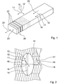
- Es zeigen:
- Fig. 1
- ein Formschaumelement und ein Zuschnittverfahren zur Herstellung von Wärmedämmelementen,
- Fig. 2
- schematisch eine Zellstruktur des Formschaumelements und
- Fig. 3
- ein Formschaumelement und ein Zuschnittverfahren zur Herstellung von Brandriegelelementen.
- Die
Figuren 1 bis 3 zeigen schematisch ein Formschaumelement aus einem Polyurethanschaum (PUR-Schaum) bzw. einen Polyisocyanuratschaum (PIR-Schaum), der gemäß einem dem Fachmann bekannten Aufschäumverfahren hergestellt wurde. Der PUR-/PIR-Schaum ist in einem kontinuierlichen Verfahren hergestellt. - In dem kontinuierlichen Aufschäumverfahren werden in einem kontinuierlichen Prozess chemische Grundstoffe, beispielsweise Polyol und Isocyanat für den PIR-Schaum, mit weiteren Zusatzstoffen gemischt und anschließend auf eine Bandanlage aufgetragen. Auf dieser Bandanlage erfolgen eine physikalische bzw. chemische Aufschäumung des Gemisches sowie gleichzeitig eine Vernetzungsreaktion der Komponenten, an deren Ende das Formschaumelement aus dem formstabilen PUR-/PIR-Schaum vorliegt. Der PUR-/PIR-Schaum wird anschließend durch Zuschnitt konfektioniert.
- Mittels der Zusatzstoffe, die teilweise als Katalysatoren für das Aufschäumverfahren wirken, einem Neigungswinkel der Bandanlage und einer Produktionsgeschwindigkeit ist ein Grad einer Anisotropie des PUR-/PIR-Schaums einstellbar. Die Katalyse steuert eine Reaktionsgeschwindigkeit, mit der die Komponenten des PUR-/PIR-Schaums miteinander reagieren. Die Katalyse ist durch die Zusatzstoffe definiert.
- Durch die Anisotropie weist das Formschaumelement eine Zellstruktur 13 auf, die drei unterscheidbare Geometriestrukturen 14, 15, 16 ausbildet. Die Geometriestrukturen 14, 15, 16 sind entlang der drei senkrecht aufeinander stehenden Raumrichtungen 10, 11, 12 orientiert. Die unterschiedlichen Geometriestrukturen 14, 15, 16 bewirken für die drei Raumrichtungen 10, 11, 12 des Formschaumelements unterschiedliche Druckspannungen.
- Die unterschiedlichen Druckspannungen wiederum führen dazu, dass das Formschaumelement in den unterschiedlichen Raumrichtungen 10, 11, 12 unterschiedlich belastbar ist. Die Belastbarkeit ist mittels geeigneter, dem Fachmann bekannter Messverfahren, bestimmbar. Zudem kann der Fachmann die unterschiedlichen Geometriestrukturen 14, 15, 16 in den drei Raumrichtungen 10, 11, 12 auch direkt mittels mikroskopischer Analyse bestimmen.
- Eine aus den Druckspannungen resultierende Belastbarkeit gemäß DIN 53421 beträgt in den einzelnen Raumrichtungen 10, 11, 12 jeweils mindestens 10 N/mm2. Entlang der ersten Raumrichtung 10 beträgt die Belastbarkeit ca. 0,14 - 0,20 N/mm2. Entlang der zweiten Raumrichtung 11 beträgt die Belastbarkeit ca. 0,11 - 0,14 N/mm2. Entlang der dritten Raumrichtung 12 beträgt die Belastbarkeit ca. 0,10 - 0,11 N/mm2.
- Die drei Raumrichtungen 10, 11, 12 sind mittels einer Produktionsrichtung 18, die durch eine Aufbringung des PUR-/PIR-Schaums auf die Bandanlage festgelegt ist, definierbar. Die Produktionsrichtung 18 entspricht einer Richtung, in der die Bandanlage verfahren wird. Das kontinuierlich aufgebrachte Formschaumelement weist eine Haupterstreckung 25 auf, die entlang der Produktionsrichtung 18 gerichtet ist.
- Die Bandanlage bildet eine Produktionsfläche aus, auf die der PUR-/PIR-Schaum aufgebracht wird. Der auf die Bandanlage aufgebrachte PUR-/PIR-Schaum schäumt nach dem Aufbringen senkrecht zu der Produktionsfläche auf. Eine Richtung senkrecht zu der Produktionsfläche ist somit als eine Aufschäumrichtung 17 definiert. Eine Richtung parallel zu der Produktionsfläche und senkrecht zu der Produktionsrichtung 18 bzw. senkrecht zu der Aufschäumrichtung 17 ist als eine Querrichtung 19 definiert.
- Die Aufschäumrichtung 17, die Produktionsrichtung 18 und die Querrichtung 19 entsprechen den drei senkrecht zueinander orientierten Raumrichtungen 10, 11, 12. Die erste Raumrichtung 10 ist parallel zu der Aufschäumrichtung 17 definiert. Die zweite Raumrichtung 11 ist parallel zu der Produktionsrichtung 18 definiert. Die dritte Raumrichtung 12 ist parallel zu der Querrichtung 19 definiert.
- Die drei unterschiedlichen Geometriestrukturen 14, 15, 16 sind als Geometrieeigenschaften ausgebildet, die durch unterschiedliche Abmessungen der Zellstruktur 13 entlang der Raumrichtungen 10, 11, 12 definiert sind. Die Zellstruktur 13 umfasst Gaszellen, die innerhalb des Polyurethans bzw. Polyisocyanurats angeordnet sind. Die Abmessungen, die die Geometriestrukturen 14, 15, 16 ausbilden, beschreiben eine räumliche Größe der Gaszellen. Einzelne Gaszellen können dabei unterschiedliche Abmessungen aufweisen. Die Geometriestrukturen 14, 15, 16 sind jeweils durch einen Mittelwert einer Größenverteilung ausgebildet, den die Abmessung der Gaszellen entlang der zugeordneten Raumrichtung 10, 11, 12 aufweist. Die Größenverteilung wird dabei innerhalb eines Einheitsvolumens, wie beispielsweise innerhalb von einem Würfel mit 1 cm Kantenlänge, bestimmt.
- Die Geometriestruktur 14, die entlang der ersten Raumrichtung 10 orientiert ist, entspricht der größten Abmessung innerhalb der Zellstruktur 13. Ihr ist daher die höchste Belastbarkeit zugeordnet. Die Geometriestruktur 16, die entlang der dritten Raumrichtung 12 orientiert ist, weist die geringste Abmessung innerhalb der Zellstruktur 13 auf. Ihr ist daher die geringste Belastbarkeit zugeordnet. Die Geometriestruktur 15, die entlang der zweiten Raumrichtung 11 orientiert ist, weist eine Abmessung auf, die größer ist als die der Geometriestruktur 16 und kleiner als die der Geometriestruktur 14. Die Geometriestrukturen 14, 15, 16 unterscheiden sich jeweils um zumindest 20%. Werte der Geometriestrukturen sind direkt mittels der oben angegebenen Belastbarkeiten bestimmbar.
- Das aus dem PUR-/PIR-Schaum hergestellte Formschaumelement weist eine Rohdichte auf, die zwischen 28 und 40 kg/m3 beträgt. Zur Ausbildung von Brandschutzriegelelementen 23 mittels des Formschaumelements wird beispielsweise ein PIR-Schaum verwendet, der eine homogene Rohdichte aufweist. Die Rohdichte beträgt dabei 32 kg/m3. Jedes Brandschutzriegelelement 23 ist in einer Form ausgestaltet, die im Wesentlichen einem prismatischen Körper, nämlich insbesondere einem Quader, entspricht. Seine rechteckige Querschnittsform besitzt eine Höhenabmessung von 220 mm und eine Materialdicke von 160 mm.
- Aus dem Formschaumelement zugeschnittene Formschaumelemente 26, die beispielsweise als Wärmedämmelemente 21 oder Brandschutzriegelelemente 23 ausgebildet sind, weisen eine Wärmeleitzahl auf, deren Rechenwert je nach einer genormten Dicke der zugeschnittenen Formschaumelemente 26 kleiner als 0,026 W/(m•K) bis 0,028 W/(m•K) ist. Bei einer Materialdicke des Wärmedämmelements 21 ab 120 mm, was einer großen Dicke zugeordnet ist, beträgt die Wärmeleitzahl beispielsweise 0,026 W/(m•K).
- Die zugeschnittenen Formschaumelemente 26 weisen Oberflächenteilbereiche auf, auf die eine Beschichtung 20 aufgebracht ist. Die Beschichtung 20 ist zum Schutz einer UV-Strahlung ausgebildet. Sie weist zumindest eine Komponente auf, die eine UV-Strahlung, wie insbesondere eine UV-A-Strahlung und eine UV-B-Strahlung, zumindest weitgehend absorbiert. Mittels der UV-Beschichtung sind die zugeschnittenen Formschaumelemente 26 insbesondere gegen eine natürliche UV-Strahlung der Sonne geschützt. Eine gesamte Oberfläche der Formschaumelemente 26 ist mit der Beschichtung überzogen.
- Zudem ist die Beschichtung 20 zur Reduzierung einer Staubbildung vorgesehen. Die Beschichtung 20 umschließt den PUR-/PIR-Schaum der Formschaumelemente 26. Der PUR-/PIR-Schaum ist dadurch innerhalb der Beschichtung 20 gebunden, wodurch eine Staubbildung durch den PUR-/PIR-Schaum unterdrückt ist. Da die Beschichtung 20 die Formschaumelemente 26 vollständig umschließt, sind die zugeschnittenen und beschichteten Formschaumelemente 26 staubfrei.
- Das kontinuierlich hergestellte, unverarbeitete Formschaumelement weist eine Haupterstreckungsrichtung 25 auf, die entlang der Produktionsrichtung 18 gerichtet ist. Zur Weiterverarbeitung wird das Formschaumelement zunächst auf einen rechteckförmigen Querschnitt zugeschnitten. Das vorverarbeitete Formschaumelement liegt danach als ein Quader vor, dessen Haupterstreckungsrichtung 25 entlang der Produktionsrichtung 18 gerichtet ist. Entlang der Aufschäumrichtung 17 weist das nun quaderförmige Formschaumelement eine Erstreckung auf, die kleiner ist als restliche Erstreckungen des vorverarbeiteten Formschaumelements. Entlang der Querrichtung 19 weist das vorverarbeitete Formschaumelement eine mittlere Erstreckung auf. Durch einen weiteren Zuschnitt kann das vorverarbeitete Formschaumelement für verschiedene Anwendungsarten konfektioniert werden.
- Wird das vorverarbeitete Formschaumelement entlang einer Ebene geschnitten, die durch die erste Raumrichtung 10 und die dritte Raumrichtung 12 definiert ist, erhält man Formschaumelemente 26, die als die Wärmedämmelemente 21 für Wärmedämm-Verbundsysteme an Gebäuden verwendet werden können. Die entlang der durch die Raumrichtungen 10, 12 definierten Ebenen geschnittenen Formschaumelemente 26 weisen Flächenerstreckungen entlang der beiden Raumrichtungen 10, 12 auf. Eine Normale 22 der Flächenerstreckung ist somit entlang der Produktionsrichtung 18 orientiert. Eine Dicke der Formschaumelemente 26, die entlang der Normale 22 der Flächenerstreckung bestimmt wird, ist dadurch entlang der zweiten Raumrichtung 11 orientiert (vgl.
Figur 1 ). - Wird das vorverarbeitete Formschaumelement zunächst entlang einer Ebene geschnitten, die durch die zweite Raumrichtung 11 und die dritte Raumrichtung 12 definiert ist, und anschließend entlang einer Ebene, die durch die erste Raumrichtung 10 und die zweite Raumrichtung 11 definiert ist, erhält man Formschaumelemente 26, die als Brandschutzriegelelemente 23 an Gebäuden verwendet werden können. Die so geschnittenen Formschaumelemente 26 weisen eine Flächenerstreckung entlang der durch die Raumrichtungen 11, 12 definierten Ebene auf. Eine Normale 24 der Flächenerstreckung ist somit entlang der Aufschäumrichtung 17 orientiert. Eine Dicke der Formschaumelemente 26, die entlang der Normale 24 der Flächenerstreckung bestimmt wird, ist dadurch entlang der ersten Raumrichtung 10 orientiert (vgl.
Figur 3 ).Bezugszeichen 10 Raumrichtung 22 Normale 11 Raumrichtung 23 Brandschutzriegelelement 12 Raumrichtung 13 Zellstruktur 24 Normale 14 Geometriestruktur 25 Haupterstreckung 15 Geometriestruktur 26 Formschaumelement 16 Geometriestruktur 17 Aufschäumrichtung 18 Produktionsrichtung 19 Querrichtung 20 Beschichtung 21 Wärmedämmelement
Claims (11)
- Formschaumelement aus Polyurethanschaum (PUR-Schaum) und/oder Polyisocyanuratschaum (PIR-Schaum), der in einem kontinuierlichen Verfahren hergestellt worden ist und eine homogene Rohdichte zwischen 28 und 40 kg/m3 aufweist, insbesondere für Wärmedämm-Verbundsysteme (WDVS) an Gebäuden, mit einer Zellstruktur (13), die in zumindest zwei senkrecht zueinander orientierten Raumrichtungen (10, 11, 12) unterscheidbare Geometriestrukturen (14, 15, 16) aufweist, und welches folienfrei ausgebildet ist.
- Formschaumelement nach Anspruch 1,
dadurch gekennzeichnet, dass
die Zellstruktur (13) den einzelnen Raumrichtungen (10, 11, 12) zugeordnete unterscheidbare Druckspannungen aufweist. - Formschaumelement nach Anspruch 1 oder 2,
dadurch gekennzeichnet, dass
die Zellstruktur (13) den einzelnen Raumrichtungen (10, 11, 12) zugeordnete unterscheidbare Druckfestigkeiten aufweist. - Formschaumelement nach einem der vorhergehenden Ansprüche,
dadurch gekennzeichnet, dass
die Zellstruktur (13) eine in einer dritten Raumrichtung (12) orientierte Geometriestruktur (16) aufweist, die unterscheidbar von den beiden anderen Geometriestrukturen (14, 15) ist. - Formschaumelement nach einem der vorhergehenden Ansprüche,
dadurch gekennzeichnet, dass
eine der Geometriestrukturen (14) entlang einer Aufschäumrichtung (17) orientiert ist. - Formschaumelement nach einem der vorhergehenden Ansprüche,
gekennzeichnet durch
eine Wärmeleitzahl, deren Rechenwert höchstens 0,028 W/(m•K) beträgt, wobei der Rechenwert ein Wert ist, der gemäß DIN EN 13165 um eine Alterungsnormkenngröße korrigiert wurde, die von einer Dicke der Wärmedämmplatte abhängt. - Formschaumelement nach einem der vorhergehenden Ansprüche,
gekennzeichnet durch
zumindest einen Oberflächenteilbereich, auf den eine Beschichtung (20) aufgebracht ist. - Formschaumelement nach Anspruch 7,
dadurch gekennzeichnet, dass
die Beschichtung (20) zum Schutz vor UV-Strahlung vorgesehen ist. - Formschaumelement nach Anspruch 7 oder 8,
dadurch gekennzeichnet, dass
die Beschichtung (20) zur Reduzierung einer Staubbildung vorgesehen ist. - Verfahren zur Herstellung wenigstens eines Wärmedämmelements (21) aus einem Formschaumelement nach einem der vorhergehenden Ansprüche,
dadurch gekennzeichnet, dass
das Formschaumelement derart zugeschnitten wird, dass eine Normale (22) einer Flächenerstreckung des Wärmedämmelements (21) entlang einer Produktionsrichtung (18) gerichtet ist. - Verfahren zur Herstellung eines Brandschutzriegelelements (23) aus einem Formschaumelement nach den Ansprüchen 1 bis 9,
dadurch gekennzeichnet, dass
das Formschaumelement derart zugeschnitten wird, dass eine Normale (24) einer Flächenerstreckung des Brandschutzriegelelements (23) entlang einer Aufschäumrichtung (17) gerichtet ist.
Applications Claiming Priority (1)
| Application Number | Priority Date | Filing Date | Title |
|---|---|---|---|
| DE102009040203A DE102009040203A1 (de) | 2009-09-07 | 2009-09-07 | Formschaumelement mit zumindest zwei unterscheidbaren Geometriestrukturen |
Publications (3)
| Publication Number | Publication Date |
|---|---|
| EP2292674A2 EP2292674A2 (de) | 2011-03-09 |
| EP2292674A3 EP2292674A3 (de) | 2013-02-20 |
| EP2292674B1 true EP2292674B1 (de) | 2020-07-29 |
Family
ID=43234266
Family Applications (1)
| Application Number | Title | Priority Date | Filing Date |
|---|---|---|---|
| EP10007930.0A Active EP2292674B1 (de) | 2009-09-07 | 2010-07-29 | Formschaumelement mit zumindest zwei unterscheidbaren Geometriestrukturen |
Country Status (2)
| Country | Link |
|---|---|
| EP (1) | EP2292674B1 (de) |
| DE (1) | DE102009040203A1 (de) |
Families Citing this family (3)
| Publication number | Priority date | Publication date | Assignee | Title |
|---|---|---|---|---|
| EP2653287A1 (de) * | 2012-04-20 | 2013-10-23 | URSA Insulation, S.A. | Dämmplatte und Verfahren zu deren Herstellung |
| EP2845959B1 (de) | 2013-09-04 | 2017-03-01 | Daw Se | Wärmedämmverbundsystem, enthaltend ein Brandriegelelement oder einen Brandriegel und Verwendung des Wärmedämmverbundsystems zur Ver- oder Behinderung einer geschossübergreifenden Brandweiterleitung |
| EP3023556B1 (de) | 2014-11-19 | 2018-02-28 | Daw Se | Brandriegelelement sowie Brandriegel gebildet aus Brandriegelelementen |
Family Cites Families (9)
| Publication number | Priority date | Publication date | Assignee | Title |
|---|---|---|---|---|
| DE4208759A1 (de) * | 1992-03-19 | 1993-09-23 | Basf Ag | Schaumstoffplatten mit verbesserten waermedaemmeigenschaften und verfahren zu ihrer herstellung |
| CZ163699A3 (cs) * | 1996-11-08 | 1999-08-11 | Huntsman Ici Chemicals, Llc | Nové pružné polyurethanové pěny |
| US20030225172A1 (en) * | 2002-05-31 | 2003-12-04 | Miller Larry M. | To enhance the thermal insulation of polymeric foam by reducing cell anisotropic ratio and the method for production thereof |
| US20040157945A1 (en) * | 2002-12-30 | 2004-08-12 | Barber Thomas Allan | Rigid urethane foams |
| DE102004011346A1 (de) * | 2004-03-05 | 2005-09-22 | Basf Ag | Verfahren zur Herstellung von Hartschaumstoffen auf Isocyanatbasis |
| GB0415629D0 (en) * | 2004-07-13 | 2004-08-18 | Leuven K U Res & Dev | Novel protective helmet |
| DE102004041143A1 (de) * | 2004-08-24 | 2006-03-02 | Basf Ag | Katalysatorsystem, insbesondere zur Herstellung von Polyurethanhartschaumstoffen |
| CA2584822A1 (en) * | 2004-11-12 | 2006-05-18 | Dow Global Technologies Inc. | Impact-absorbing members for dynamic impact applications |
| JPWO2008069013A1 (ja) * | 2006-12-05 | 2010-03-18 | 株式会社カネカ | エネルギー吸収材に適した樹脂発泡体 |
-
2009
- 2009-09-07 DE DE102009040203A patent/DE102009040203A1/de not_active Ceased
-
2010
- 2010-07-29 EP EP10007930.0A patent/EP2292674B1/de active Active
Non-Patent Citations (1)
| Title |
|---|
| None * |
Also Published As
| Publication number | Publication date |
|---|---|
| DE102009040203A1 (de) | 2011-03-10 |
| EP2292674A3 (de) | 2013-02-20 |
| EP2292674A2 (de) | 2011-03-09 |
Similar Documents
| Publication | Publication Date | Title |
|---|---|---|
| EP1678386B2 (de) | Dämmstoffelement aus Mineralfaserfilz für den klemmenden Einbau zwischen Balken | |
| EP2501749B1 (de) | Mikrohohlkugeln enthaltende harzschaumstoffe | |
| EP3938158B1 (de) | Plattenförmiger werkstoff und verfahren zu dessen herstellung | |
| EP1749805B1 (de) | Gipsbaustoffe mit erhöhter wärmeleitfähigkeit und abschirmung gegen elektromagnetische strahlen. | |
| DE3625534A1 (de) | Bauplatte | |
| WO2012163460A1 (de) | Energiespeichermodul aus mehreren insbesondere prismatischen speicherzellen und verfahren zur herstellung eines energiespeichermoduls sowie verfahren zur herstellung einer endplatte für ein energiespeichermodul | |
| DE20307608U1 (de) | Dämmender geschäumter Werkstoff | |
| EP3680509A1 (de) | Sandwichplatte mit akustischen dämpfungseigenschaften | |
| EP2292674B1 (de) | Formschaumelement mit zumindest zwei unterscheidbaren Geometriestrukturen | |
| EP0561216B2 (de) | Schaumstoffplatten mit verbesserten Wärmedämmeigenschaften und Verfahren zu ihrer Herstellung | |
| EP2147762B1 (de) | Fußbodenpaneel aus einer Holzwerkstoffplatte und Verfahren zur Herstellung | |
| DE102009046257A1 (de) | Plattenförmige Isolationslage für eine Wand, Verfahren zu deren Herstellung sowie plattenförmiges Wandelement | |
| EP3725481A1 (de) | Plattenförmiger werkstoff und verfahren zu dessen herstellung | |
| EP0947638B1 (de) | Dämmplatte zur Verwendung an Aussenfassaden von Häusern | |
| WO2008128733A1 (de) | Fassadendämmplatte für die dämmung von aussenfassaden von gebäuden, wärmedämm-verbundsystem mit derartigen fassadendämmplatten sowie verfahren zur herstellung einer fassadendämmplatte | |
| DE102007018209A1 (de) | Dämmplatte | |
| AT526148B1 (de) | Holzverbundelement und Verfahren zu dessen Herstellung | |
| EP3603971A1 (de) | Bauelement, wandelement für ein bauwerk und verfahren zum herstellen eines bauelementes | |
| DE202022101604U1 (de) | Inlay für Metalltüren | |
| DE8617998U1 (de) | Plattenförmiges Verbundelement | |
| EP0959190A2 (de) | Wärmedämmelement | |
| DE102012110225A1 (de) | Wärmedämmelement | |
| DE29919919U1 (de) | Feuerhemmende Sandwichplatte | |
| EP2385208B1 (de) | Holzrahmen für eine absturzsichernde Verglasung | |
| EP1457615A1 (de) | Wandelement mit Styroporkugeln |
Legal Events
| Date | Code | Title | Description |
|---|---|---|---|
| PUAI | Public reference made under article 153(3) epc to a published international application that has entered the european phase |
Free format text: ORIGINAL CODE: 0009012 |
|
| AK | Designated contracting states |
Kind code of ref document: A2 Designated state(s): AL AT BE BG CH CY CZ DE DK EE ES FI FR GB GR HR HU IE IS IT LI LT LU LV MC MK MT NL NO PL PT RO SE SI SK SM TR |
|
| AX | Request for extension of the european patent |
Extension state: BA ME RS |
|
| PUAL | Search report despatched |
Free format text: ORIGINAL CODE: 0009013 |
|
| AK | Designated contracting states |
Kind code of ref document: A3 Designated state(s): AL AT BE BG CH CY CZ DE DK EE ES FI FR GB GR HR HU IE IS IT LI LT LU LV MC MK MT NL NO PL PT RO SE SI SK SM TR |
|
| AX | Request for extension of the european patent |
Extension state: BA ME RS |
|
| RIC1 | Information provided on ipc code assigned before grant |
Ipc: C08G 18/08 20060101AFI20130111BHEP Ipc: E04B 1/94 20060101ALI20130111BHEP |
|
| 17P | Request for examination filed |
Effective date: 20130819 |
|
| RBV | Designated contracting states (corrected) |
Designated state(s): AL AT BE BG CH CY CZ DE DK EE ES FI FR GB GR HR HU IE IS IT LI LT LU LV MC MK MT NL NO PL PT RO SE SI SK SM TR |
|
| 17Q | First examination report despatched |
Effective date: 20141001 |
|
| STAA | Information on the status of an ep patent application or granted ep patent |
Free format text: STATUS: EXAMINATION IS IN PROGRESS |
|
| GRAP | Despatch of communication of intention to grant a patent |
Free format text: ORIGINAL CODE: EPIDOSNIGR1 |
|
| STAA | Information on the status of an ep patent application or granted ep patent |
Free format text: STATUS: GRANT OF PATENT IS INTENDED |
|
| RIC1 | Information provided on ipc code assigned before grant |
Ipc: B29C 44/34 20060101ALI20200205BHEP Ipc: C08G 101/00 20060101ALN20200205BHEP Ipc: B29K 75/00 20060101ALI20200205BHEP Ipc: E04B 1/94 20060101ALI20200205BHEP Ipc: E04B 1/76 20060101ALI20200205BHEP Ipc: C08G 18/08 20060101AFI20200205BHEP |
|
| INTG | Intention to grant announced |
Effective date: 20200221 |
|
| GRAS | Grant fee paid |
Free format text: ORIGINAL CODE: EPIDOSNIGR3 |
|
| GRAA | (expected) grant |
Free format text: ORIGINAL CODE: 0009210 |
|
| STAA | Information on the status of an ep patent application or granted ep patent |
Free format text: STATUS: THE PATENT HAS BEEN GRANTED |
|
| AK | Designated contracting states |
Kind code of ref document: B1 Designated state(s): AL AT BE BG CH CY CZ DE DK EE ES FI FR GB GR HR HU IE IS IT LI LT LU LV MC MK MT NL NO PL PT RO SE SI SK SM TR |
|
| REG | Reference to a national code |
Ref country code: GB Ref legal event code: FG4D Free format text: NOT ENGLISH |
|
| REG | Reference to a national code |
Ref country code: CH Ref legal event code: EP |
|
| REG | Reference to a national code |
Ref country code: AT Ref legal event code: REF Ref document number: 1295705 Country of ref document: AT Kind code of ref document: T Effective date: 20200815 |
|
| REG | Reference to a national code |
Ref country code: IE Ref legal event code: FG4D Free format text: LANGUAGE OF EP DOCUMENT: GERMAN |
|
| REG | Reference to a national code |
Ref country code: DE Ref legal event code: R096 Ref document number: 502010016710 Country of ref document: DE |
|
| REG | Reference to a national code |
Ref country code: CH Ref legal event code: NV Representative=s name: PATENTANWALTSKANZLEI DAUB, CH |
|
| REG | Reference to a national code |
Ref country code: NL Ref legal event code: FP |
|
| REG | Reference to a national code |
Ref country code: LT Ref legal event code: MG4D |
|
| PG25 | Lapsed in a contracting state [announced via postgrant information from national office to epo] |
Ref country code: NO Free format text: LAPSE BECAUSE OF FAILURE TO SUBMIT A TRANSLATION OF THE DESCRIPTION OR TO PAY THE FEE WITHIN THE PRESCRIBED TIME-LIMIT Effective date: 20201029 Ref country code: BG Free format text: LAPSE BECAUSE OF FAILURE TO SUBMIT A TRANSLATION OF THE DESCRIPTION OR TO PAY THE FEE WITHIN THE PRESCRIBED TIME-LIMIT Effective date: 20201029 Ref country code: ES Free format text: LAPSE BECAUSE OF FAILURE TO SUBMIT A TRANSLATION OF THE DESCRIPTION OR TO PAY THE FEE WITHIN THE PRESCRIBED TIME-LIMIT Effective date: 20200729 Ref country code: PT Free format text: LAPSE BECAUSE OF FAILURE TO SUBMIT A TRANSLATION OF THE DESCRIPTION OR TO PAY THE FEE WITHIN THE PRESCRIBED TIME-LIMIT Effective date: 20201130 Ref country code: SE Free format text: LAPSE BECAUSE OF FAILURE TO SUBMIT A TRANSLATION OF THE DESCRIPTION OR TO PAY THE FEE WITHIN THE PRESCRIBED TIME-LIMIT Effective date: 20200729 Ref country code: GR Free format text: LAPSE BECAUSE OF FAILURE TO SUBMIT A TRANSLATION OF THE DESCRIPTION OR TO PAY THE FEE WITHIN THE PRESCRIBED TIME-LIMIT Effective date: 20201030 Ref country code: FI Free format text: LAPSE BECAUSE OF FAILURE TO SUBMIT A TRANSLATION OF THE DESCRIPTION OR TO PAY THE FEE WITHIN THE PRESCRIBED TIME-LIMIT Effective date: 20200729 Ref country code: HR Free format text: LAPSE BECAUSE OF FAILURE TO SUBMIT A TRANSLATION OF THE DESCRIPTION OR TO PAY THE FEE WITHIN THE PRESCRIBED TIME-LIMIT Effective date: 20200729 Ref country code: LT Free format text: LAPSE BECAUSE OF FAILURE TO SUBMIT A TRANSLATION OF THE DESCRIPTION OR TO PAY THE FEE WITHIN THE PRESCRIBED TIME-LIMIT Effective date: 20200729 |
|
| PG25 | Lapsed in a contracting state [announced via postgrant information from national office to epo] |
Ref country code: IS Free format text: LAPSE BECAUSE OF FAILURE TO SUBMIT A TRANSLATION OF THE DESCRIPTION OR TO PAY THE FEE WITHIN THE PRESCRIBED TIME-LIMIT Effective date: 20201129 Ref country code: LV Free format text: LAPSE BECAUSE OF FAILURE TO SUBMIT A TRANSLATION OF THE DESCRIPTION OR TO PAY THE FEE WITHIN THE PRESCRIBED TIME-LIMIT Effective date: 20200729 Ref country code: PL Free format text: LAPSE BECAUSE OF FAILURE TO SUBMIT A TRANSLATION OF THE DESCRIPTION OR TO PAY THE FEE WITHIN THE PRESCRIBED TIME-LIMIT Effective date: 20200729 |
|
| PG25 | Lapsed in a contracting state [announced via postgrant information from national office to epo] |
Ref country code: EE Free format text: LAPSE BECAUSE OF FAILURE TO SUBMIT A TRANSLATION OF THE DESCRIPTION OR TO PAY THE FEE WITHIN THE PRESCRIBED TIME-LIMIT Effective date: 20200729 Ref country code: DK Free format text: LAPSE BECAUSE OF FAILURE TO SUBMIT A TRANSLATION OF THE DESCRIPTION OR TO PAY THE FEE WITHIN THE PRESCRIBED TIME-LIMIT Effective date: 20200729 Ref country code: RO Free format text: LAPSE BECAUSE OF FAILURE TO SUBMIT A TRANSLATION OF THE DESCRIPTION OR TO PAY THE FEE WITHIN THE PRESCRIBED TIME-LIMIT Effective date: 20200729 Ref country code: SM Free format text: LAPSE BECAUSE OF FAILURE TO SUBMIT A TRANSLATION OF THE DESCRIPTION OR TO PAY THE FEE WITHIN THE PRESCRIBED TIME-LIMIT Effective date: 20200729 Ref country code: MC Free format text: LAPSE BECAUSE OF FAILURE TO SUBMIT A TRANSLATION OF THE DESCRIPTION OR TO PAY THE FEE WITHIN THE PRESCRIBED TIME-LIMIT Effective date: 20200729 |
|
| REG | Reference to a national code |
Ref country code: DE Ref legal event code: R097 Ref document number: 502010016710 Country of ref document: DE |
|
| PG25 | Lapsed in a contracting state [announced via postgrant information from national office to epo] |
Ref country code: AL Free format text: LAPSE BECAUSE OF FAILURE TO SUBMIT A TRANSLATION OF THE DESCRIPTION OR TO PAY THE FEE WITHIN THE PRESCRIBED TIME-LIMIT Effective date: 20200729 |
|
| PLBE | No opposition filed within time limit |
Free format text: ORIGINAL CODE: 0009261 |
|
| STAA | Information on the status of an ep patent application or granted ep patent |
Free format text: STATUS: NO OPPOSITION FILED WITHIN TIME LIMIT |
|
| GBPC | Gb: european patent ceased through non-payment of renewal fee |
Effective date: 20201029 |
|
| PG25 | Lapsed in a contracting state [announced via postgrant information from national office to epo] |
Ref country code: SK Free format text: LAPSE BECAUSE OF FAILURE TO SUBMIT A TRANSLATION OF THE DESCRIPTION OR TO PAY THE FEE WITHIN THE PRESCRIBED TIME-LIMIT Effective date: 20200729 |
|
| 26N | No opposition filed |
Effective date: 20210430 |
|
| PG25 | Lapsed in a contracting state [announced via postgrant information from national office to epo] |
Ref country code: SI Free format text: LAPSE BECAUSE OF FAILURE TO SUBMIT A TRANSLATION OF THE DESCRIPTION OR TO PAY THE FEE WITHIN THE PRESCRIBED TIME-LIMIT Effective date: 20200729 Ref country code: GB Free format text: LAPSE BECAUSE OF NON-PAYMENT OF DUE FEES Effective date: 20201029 Ref country code: IE Free format text: LAPSE BECAUSE OF NON-PAYMENT OF DUE FEES Effective date: 20200729 |
|
| PG25 | Lapsed in a contracting state [announced via postgrant information from national office to epo] |
Ref country code: TR Free format text: LAPSE BECAUSE OF FAILURE TO SUBMIT A TRANSLATION OF THE DESCRIPTION OR TO PAY THE FEE WITHIN THE PRESCRIBED TIME-LIMIT Effective date: 20200729 Ref country code: MT Free format text: LAPSE BECAUSE OF FAILURE TO SUBMIT A TRANSLATION OF THE DESCRIPTION OR TO PAY THE FEE WITHIN THE PRESCRIBED TIME-LIMIT Effective date: 20200729 Ref country code: CY Free format text: LAPSE BECAUSE OF FAILURE TO SUBMIT A TRANSLATION OF THE DESCRIPTION OR TO PAY THE FEE WITHIN THE PRESCRIBED TIME-LIMIT Effective date: 20200729 |
|
| PG25 | Lapsed in a contracting state [announced via postgrant information from national office to epo] |
Ref country code: MK Free format text: LAPSE BECAUSE OF FAILURE TO SUBMIT A TRANSLATION OF THE DESCRIPTION OR TO PAY THE FEE WITHIN THE PRESCRIBED TIME-LIMIT Effective date: 20200729 |
|
| P01 | Opt-out of the competence of the unified patent court (upc) registered |
Effective date: 20230519 |
|
| PGFP | Annual fee paid to national office [announced via postgrant information from national office to epo] |
Ref country code: NL Payment date: 20230720 Year of fee payment: 14 |
|
| PGFP | Annual fee paid to national office [announced via postgrant information from national office to epo] |
Ref country code: BE Payment date: 20230719 Year of fee payment: 14 |
|
| REG | Reference to a national code |
Ref country code: NL Ref legal event code: MM Effective date: 20240801 |
|
| PG25 | Lapsed in a contracting state [announced via postgrant information from national office to epo] |
Ref country code: NL Free format text: LAPSE BECAUSE OF NON-PAYMENT OF DUE FEES Effective date: 20240801 |
|
| PG25 | Lapsed in a contracting state [announced via postgrant information from national office to epo] |
Ref country code: BE Free format text: LAPSE BECAUSE OF NON-PAYMENT OF DUE FEES Effective date: 20240731 |
|
| REG | Reference to a national code |
Ref country code: BE Ref legal event code: MM Effective date: 20240731 |
|
| PGFP | Annual fee paid to national office [announced via postgrant information from national office to epo] |
Ref country code: LU Payment date: 20250722 Year of fee payment: 16 |
|
| REG | Reference to a national code |
Ref country code: DE Ref legal event code: R082 Ref document number: 502010016710 Country of ref document: DE Representative=s name: DAUB PARTG MBB, DE |
|
| PGFP | Annual fee paid to national office [announced via postgrant information from national office to epo] |
Ref country code: DE Payment date: 20250722 Year of fee payment: 16 |
|
| PGFP | Annual fee paid to national office [announced via postgrant information from national office to epo] |
Ref country code: IT Payment date: 20250731 Year of fee payment: 16 |
|
| PGFP | Annual fee paid to national office [announced via postgrant information from national office to epo] |
Ref country code: FR Payment date: 20250723 Year of fee payment: 16 Ref country code: AT Payment date: 20250721 Year of fee payment: 16 |
|
| PGFP | Annual fee paid to national office [announced via postgrant information from national office to epo] |
Ref country code: CH Payment date: 20250801 Year of fee payment: 16 |
|
| PGFP | Annual fee paid to national office [announced via postgrant information from national office to epo] |
Ref country code: CZ Payment date: 20250717 Year of fee payment: 16 |