EP2292976B1 - Dispositif de chauffage par rayonnement - Google Patents
Dispositif de chauffage par rayonnement Download PDFInfo
- Publication number
- EP2292976B1 EP2292976B1 EP10172233.8A EP10172233A EP2292976B1 EP 2292976 B1 EP2292976 B1 EP 2292976B1 EP 10172233 A EP10172233 A EP 10172233A EP 2292976 B1 EP2292976 B1 EP 2292976B1
- Authority
- EP
- European Patent Office
- Prior art keywords
- pressure
- burner
- mbar
- combustion air
- combustion
- Prior art date
- Legal status (The legal status is an assumption and is not a legal conclusion. Google has not performed a legal analysis and makes no representation as to the accuracy of the status listed.)
- Not-in-force
Links
Images
Classifications
-
- F—MECHANICAL ENGINEERING; LIGHTING; HEATING; WEAPONS; BLASTING
- F23—COMBUSTION APPARATUS; COMBUSTION PROCESSES
- F23N—REGULATING OR CONTROLLING COMBUSTION
- F23N5/00—Systems for controlling combustion
- F23N5/24—Preventing development of abnormal or undesired conditions, i.e. safety arrangements
- F23N5/242—Preventing development of abnormal or undesired conditions, i.e. safety arrangements using electronic means
-
- F—MECHANICAL ENGINEERING; LIGHTING; HEATING; WEAPONS; BLASTING
- F23—COMBUSTION APPARATUS; COMBUSTION PROCESSES
- F23D—BURNERS
- F23D14/00—Burners for combustion of a gas, e.g. of a gas stored under pressure as a liquid
- F23D14/12—Radiant burners
- F23D14/126—Radiant burners cooperating with refractory wall surfaces
-
- F—MECHANICAL ENGINEERING; LIGHTING; HEATING; WEAPONS; BLASTING
- F23—COMBUSTION APPARATUS; COMBUSTION PROCESSES
- F23N—REGULATING OR CONTROLLING COMBUSTION
- F23N3/00—Regulating air supply or draught
- F23N3/002—Regulating air supply or draught using electronic means
-
- F—MECHANICAL ENGINEERING; LIGHTING; HEATING; WEAPONS; BLASTING
- F23—COMBUSTION APPARATUS; COMBUSTION PROCESSES
- F23N—REGULATING OR CONTROLLING COMBUSTION
- F23N2225/00—Measuring
- F23N2225/04—Measuring pressure
- F23N2225/06—Measuring pressure for determining flow
-
- F—MECHANICAL ENGINEERING; LIGHTING; HEATING; WEAPONS; BLASTING
- F23—COMBUSTION APPARATUS; COMBUSTION PROCESSES
- F23N—REGULATING OR CONTROLLING COMBUSTION
- F23N2231/00—Fail safe
- F23N2231/18—Detecting fluid leaks
-
- F—MECHANICAL ENGINEERING; LIGHTING; HEATING; WEAPONS; BLASTING
- F23—COMBUSTION APPARATUS; COMBUSTION PROCESSES
- F23N—REGULATING OR CONTROLLING COMBUSTION
- F23N5/00—Systems for controlling combustion
- F23N5/18—Systems for controlling combustion using detectors sensitive to rate of flow of air or fuel
Definitions
- the invention relates to a radiant heater and a method for monitoring the radiant heater.
- the invention relates to a radiant heater for a furnace, such as an industrial furnace, and to a method of monitoring such a radiant heater having at least one burner disposed within a ceramic radiant tube and connected via a combustion gas line to a gas manifold and via a combustion air line to an air manifold is.
- recuperative burners are used, in which the heat of exhaust gases is used for Verbrennungs Kunststoffvormaschinermung.
- at least one burner and a recuperator are associated with a radiant heating tube.
- the aim is to transfer as much of the exhaust heat as possible to the air.
- part of the exhaust gas flowing back into the radiant heating pipe is used for preheating the combustion air or fresh air, the heat transfer or the heat exchange taking place in the recuperator.
- Such burners are used in industrial furnaces heated indirectly with radiant tubes, in which the material introduced into the furnace chamber or the atmosphere present in the furnace chamber must not be exposed to exhaust gases and / or contaminated.
- the known Strahlhardrohre consist of at least one burner with a burner nozzle, a combustion air supply and a combustion tube and an outer tube.
- the outer tube or jacket tube is closed by a bottom, so that the exhaust gases are returned to an annular space between the combustion tube and outer tube.
- a recuperator is installed, by means of which the combustion air necessary for the operation of the burner is preheated in countercurrent.
- the exhaust gases leave the outer pipe via an annular gap and are passed directly or via an exhaust gas collecting head into a pipe system.
- From the EP 1 479 973 A2 is a method and apparatus for monitoring the tightness of a steel tube fired by a gas burner.
- a trained as a differential pressure sensor sensor is used to monitor the exhaust gas flow of the gas burner and outputs when exceeding a predetermined threshold, a characteristic of this exhaust signal.
- the exhaust gas signal together with a burner signal indicating the on-state of the burner, is supplied to a monitoring circuit which outputs an error signal in the event of an inadmissible combination of the burner signal and the exhaust gas signal.
- the differential pressure measurement takes place with the aid of a differential pressure diaphragm which is arranged in the exhaust gas flow.
- a method for monitoring a furnace using a responsive to the O 2 partial pressure in the exhaust gas sensor known.
- the output signal of the measuring sensor is evaluated in a controller, wherein a warning signal is output in response to a corresponding signal change in order to close shut-off devices of the media accesses and outlets.
- the O 2 partial pressure is used to monitor the combustion, whether it is stoichiometric (normal operating range) or sub-stoichiometric (flame extinguished or unfavorable combustion conditions).
- a change of combustion from the superstoichiometric to the substoichiometric range causes a sudden change in the output signal, so that the warning signal is generated. If the radiant tube breaks, a clear displacement of the measuring signal likewise results, so that cracks in the jacket tube can be detected by such a characteristic signal change.
- the invention has for its object to provide a solution that provides a simplified and improved way of monitoring a jet heater in a structurally simple manner and cost.
- the method according to the invention is suitable for monitoring a jet heating device which is used for indirect heating or cooling of a furnace installation, in particular an industrial furnace, wherein the jet heating device has at least one burner, which is arranged inside a ceramic radiant heating pipe and via a combustion gas duct to a gas manifold and via a combustion air duct is connected to an air manifold.
- the at least one burner is supplied for indirect heating of the furnace system with combustion air and combustion gas.
- the at least one burner is supplied exclusively with cooling air.
- the pressure of combustion air guided in the combustion air line and the pressure of combustion gas in the combustion gas line led to the supply to the at least one burner is lowered to a respective predetermined pressure.
- the supply of the combustion air and / or the combustion gas to the at least one burner are monitored by a monitoring device arranged in the combustion air line and / or in the combustion gas line. During monitoring, the monitoring device determines a current pressure of the combustion air and / or the combustion gas immediately before it is fed to the at least one burner.
- a signal indicating a leakage of the ceramic radiant heat pipe is output when the pressure currently detected by the monitoring device falls below a predetermined limit value and / or when a pressure difference ⁇ p formed from the currently determined pressure and a pressure of a corresponding manifold exceeds a limit value.
- the jet heating device for a furnace installation, in particular for an industrial furnace, has at least one burner which is arranged within a ceramic radiant heat pipe and is connected via a combustion gas line to a gas manifold and via a combustion air line to an air manifold.
- a monitoring device for determining a current pressure is provided in the combustion air line and / or in the combustion gas line immediately before entering the housing of the at least one burner and outputs the currently determined pressure to a burner control.
- the monitoring device and / or the burner control is configured such that it compares the currently determined pressure with a predetermined limit value and / or a pressure difference ⁇ p formed from a currently determined pressure and a pressure of a corresponding manifold with a predetermined Limit value is compared.
- the monitoring device and / or the burner control device also outputs a signal indicating a leakage of the ceramic radiant heat pipe if the currently determined pressure falls below the predetermined limit value and / or if the pressure difference ⁇ p formed from the currently determined pressure and a pressure of a corresponding manifold exceeds a predetermined limit value ,
- the invention provides a possibility with which a damage of a radiant heating pipe is reliably detected and, moreover, it is prevented that, in the event of damage, a material introduced into a furnace during a heat treatment is exposed to exhaust gases and contaminated.
- the monitoring is just as safe for a furnace system, which will operate with protective or reaction gas. According to the invention, this is achieved by continuously monitoring a characteristic pressure value in the combustion air line and / or in the combustion gas line.
- a value of 10 mbar, preferably of 5 mbar, more preferably of 3 mbar, in particular of 2 mbar, can be used.
- the limit value for the pressure difference ⁇ p formed may be 70 mbar, preferably 50 mbar, more preferably 30 mbar.
- the monitoring device comprises a pressure switch.
- a recuperator is present, which uses a portion of the flowing gas in the ceramic radiant heat pipe for preheating the combustion air.
- the invention provides for the use of at least one radiant heater according to any one of claims 4 to 8 using the method of any of claims 1 to 3 for heating or cooling a furnace.
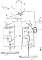
- FIG. 1 a schematic representation of a radiant heater according to the invention 1.
- the radiant heater 1 has a burner 2, not shown in detail on the type of a recuperative burner.
- the burner 2 within a hollow casing tube, the so-called radiant tube 3 of the radiant heater 1, arranged and has to monitor a flame monitoring device or a flame detector (for example, a UV monitoring) 4, which is or is coupled to a burner control 5 ,
- the radiant tube 3 is usually made of a ceramic material, wherein a metallic radiant tube 3 is conceivable.
- the burner controller 5 designed as a gas burner control unit is configured such that it can indicate operating and fault states of the radiant heater device 1.
- the burner control 5 serves to ignite and control the burner 2, to set various operations of the radiant heater 1 and to control the supply of combustion air and combustion gas.
- the various modes of operation of the burner control unit 5 can be input via a programmable logic controller (PLC) 6.
- PLC programmable logic controller
- the programmable logic controller (PLC) 6 realizes the control and regulation of the burner 2 via the burner control 5 and thereby takes over the flexible part for implementing various modes of operation.
- the programmable logic controller (PLC) 6 can also connect to a central computer or computer, which takes over the control and regulation of a variety of burners 2 and beam heaters 1 a furnace.
- the burner 2 is supplied with combustion air and combustion gas.
- the combustion air of an air manifold 7 and passes through a combustion air line 8 to the burner 2. Further, the combustion gas required for combustion of a gas manifold 9 is removed and passes through a combustion gas line 10 to the burner.
- a manual shut-off valve 11 for manually opening or closing the combustion air supply
- a compensator 12 to compensate for movements in the combustion air duct 8 due to vibration or thermal expansion or shortening
- a metering orifice 13 with a differential switch 14
- a metering valve 15 for easy Setting and precise metering of the combustion air
- a pressure switch 17 is arranged downstream of the solenoid valve 16 and upstream of the burner 2. The pressure switch 17 is coupled to the burner control 5 and designed such that it outputs a signal and / or a pressure value of the combustion air to the burner control unit 5 falls below a predetermined minimum pressure of the combustion air.
- a manual shut-off valve 18 for manually opening or closing the combustion gas supply, a movement in the combustion air duct 8 due to vibrations or thermal expansions or compensations compensating Kompensator 19, a metering orifice 20 with a differential switch 21, a for easy adjustment and precise metering of the combustion gas provided metering valve 22 and a coupled to the burner control 5 solenoid valve 23 is arranged. Downstream of the solenoid valve 23 and upstream of the burner 2, a pressure switch 24 coupled to the burner control 5 is provided, which outputs a signal and / or a pressure value of the combustion gas to the burner control 5 when the combustion gas is below a predetermined minimum pressure.
- the jet heater 1 is a part in a in FIG. 1 not shown wall of a furnace system, in particular an industrial furnace, installed, wherein at least the radiant tube 3 protrudes into the oven interior 25 in order to heat it by means of thermal radiation.
- a furnace system in particular an industrial furnace
- radiant tube 3 protrudes into the oven interior 25 in order to heat it by means of thermal radiation.
- more radiant heaters are of course provided, which are installed side by side lying in the furnace wall and ensure uniform heating of the oven interior 25 and a material introduced therein.
- the combustion gases or exhaust gases recirculated via the radiant heating pipe 3 pass via an outlet of the radiant heating pipe 3 and a train breaker 27 into an exhaust pipe 26.
- the combustion air pressure at the manual shut-off valve 11 of the burner 2 is at least 40 mbar (about 400 mmWS), if possible 60 or 80 mbar (about 600 or 800 mmWS). During operation, the combustion air pressure at the manual shut-off valve 11 of the burner 2 is kept constant with a tolerance of +/- 5%.
- the reduction of the combustion air pressure to the pressure in the radiant tube 3 of about 10 mbar (about 100 mmWS) at full load operation of the burner 2 takes place in the fittings of Combustion air line 8, ie in Handabsperrventil 11, the metering orifice 13 and the metering valve 15, and the air side in the recuperator of the burner 2, ie in the part of the burner 2, through which the combustion air flows for heat exchange with the hot exhaust gas.
- the air-side pressure loss in the recuperator ie the pressure loss of the preheated in the burner 2 combustion air, is also in the order of 10 mbar (about 100 mmWS).
- the pressure of the combustion gas in the combustion gas line 10 is at Handbarperrventil 18 at least 40 mbar (about 400 mmWS), if possible 60 mbar (about 600 mmWS). Diester pressure of the combustion gas at Handabsperrventil 18 of the burner 2 is also kept constant with a tolerance of +/- 5%.
- the pressure of the combustion gas in the combustion gas line 10 is reduced to about the pressure in the radiant tube 3 of about 10 mbar (about 100 mmWS), wherein the pressure reduction in the manual shut-off valve 18, the orifice 20, in the metering valve 22 and takes place in the gas nozzles in the burner mouth of the burner 2.
- the pressure loss in the gas nozzles in the burner mouth is on the order of 10 to 20 mbar (about 100 to 200 mmWS).
- the pressure of guided in the combustion air duct 8 combustion air and the pressure of guided in the combustion gas duct 10 combustion gas is lowered to a supply to the burner 2 to a respective predetermined pressure.
- the supply of the combustion air and the combustion gas are monitored by a respective monitoring device in the form of the pressure switch 17 and 24, wherein each of the two pressure switches 17, 24 a current pressure of the combustion air and the combustion gas immediately upstream of the burner 2 before being supplied to the burner 2 are determined.
- the radiant tube 3 is damaged or broken, take the combustion exhaust no longer the way on the recuperator to the exhaust pipe 26, but occur without much pressure loss in the furnace interior 25 from.
- the pressure in the furnace interior 25 usually lies at less than 1 mbar, for example 0.1 to 0.5 mbar (about 1 to 5 mmWS).
- the pressure increases slightly.
- the pressure of the combustion air and / or the pressure of the combustion gas is monitored immediately before entry into the burner 2 with a monitoring device in the form of the pressure switch 17 or 24. If at full load operation of the burner 2, the pressure of the combustion air and / or the pressure of the combustion gas at the pressure switches 17, 24 falls below a predetermined limit, there is damage to the Strahlsammlungrohres 3, which by a corresponding output from the pressure switch 17 to the burner control 5 Signal is displayed.
- the use of only one pressure switch 17 or 24 is sufficient to determine damage to the radiant tube 3 and to monitor the tightness of the Strahlskyrohres 3.
- Preferably only one pressure switch 17 is used in the combustion air line 8.
- the ratio of the air-side pressure loss in the recuperator to the exhaust-side pressure loss in the recuperator is smaller than the ratio of the pressure loss in the gas nozzles to the exhaust-side pressure loss in the recuperator, so that instead of using a pressure switch in the combustion gas line 10, the use of a pressure switch 17 in the combustion air line. 8 due to the higher sensitivity is more appropriate.
- the pressure drop in the combustion air line 8 and / or the combustion gas line 10 that indicates damage to the radiant heating pipe 3 can also be detected by a pressure difference ⁇ p falling below a limit value.
- the pressure difference .DELTA.p is hiebei from a currently determined pressure value, for example, at the position of the pressure transducer 17, 24, and a corresponding pressure which in the manifold, i. the air manifold 7 or the gas manifold 9, prevails at the transition to the combustion air duct 8 or to the combustion gas duct 10 determined.
- a corresponding signal is thus output, which can be output directly from one or both of the pressure switches 17, 24 or from the burner control 5.
- This signal is output when the currently determined by at least one of the two pressure switches 17, 24 pressure falls below a predetermined limit.
- a value between 2 mbar and 10 mbar can be used as the limit value for the currently determined pressure.
- this signal can also be output when a pressure difference ⁇ p formed from the currently determined pressure and a pressure of a corresponding manifold (air manifold 7 or gas manifold 9) exceeds a limit value.
- a limit value for the pressure difference .DELTA.p formed a value between 30 mbar and 70 mbar is considered.
- the jet heater 1 can not be used only for heating the oven interior 25.
- the air from a combustion air fan but also air from a separate cooling fan can be used.
- Possible damage or breakage of the radiant tube 3 is then also detected as above in the operation for heating the oven interior 25 by detecting the pressure drop from the pressure switch 17 and outputting it to the burner controller 5, which then further processes this signal to supply the air to prevent radiant heating pipe 3 or to take measures to switch off the radiant tube 3.
- the current pressure or the pressure difference .DELTA.p and a signal indicating the operating state of the burner can also be linked to each other, so that in an inadmissible combination of the operating state of the A heating device (heating or cooling) indicating signal and the current pressure or the current pressure difference .DELTA.p a signal indicating damage to the radiant tube 3 is output from at least one of the two pressure switches 17, 24 and measures for switching off the jet heater 3 and the burner 2 are executed become.
Landscapes
- Engineering & Computer Science (AREA)
- Chemical & Material Sciences (AREA)
- Combustion & Propulsion (AREA)
- Mechanical Engineering (AREA)
- General Engineering & Computer Science (AREA)
- Combustion Of Fluid Fuel (AREA)
- Regulation And Control Of Combustion (AREA)
Claims (8)
- Procédé destiné à la surveillance d'un dispositif de chauffage rayonnant (1) pour le chauffage ou le refroidissement indirect d'une installation de four, en particulier d'un four industriel, dans lequel le dispositif de chauffage rayonnant (1) présente au moins un brûleur (2) qui est disposé à l'intérieur d'un tube de chauffage rayonnant céramique (3) et est raccordé à une conduite de collecte de gaz (9) par le biais d'une conduite de gaz de combustion (10) et à une conduite de collecte d'air (7) par le biais d'une conduite d'air de combustion (8),
dans lequel l'au moins un brûleur (2) est alimenté en air de combustion et en gaz de combustion pour le chauffage indirect ou bien l'au moins un brûleur (2) est alimenté exclusivement en air de refroidissement pour le refroidissement indirect,
dans lequel, en cas de chauffage indirect de l'installation de four, la pression de l'air de combustion amené dans la conduite d'air de combustion (8) et la pression du gaz de combustion amené dans la conduite de gaz de combustion (10) sont baissés à une pression prédéfinie respective jusqu'à l'amenée vers au moins un brûleur (2),
dans lequel l'amenée de l'air de combustion et/ou du gaz de combustion vers l'au moins un brûleur (2) est surveillée par un dispositif de surveillance disposé dans la conduite d'air de combustion (8) et/ou dans la conduite de gaz de combustion (10),
dans lequel une pression en cours de l'air de combustion et/ou du gaz de combustion est calculée par le dispositif de surveillance directement avant l'amenée vers l'au moins un brûleur (2),
dans lequel un signal indiquant un défaut d'étanchéité du tube de chauffage rayonnant céramique (3) est émis lorsque la pression en cours calculée par le dispositif de surveillance est en-deçà d'une valeur limite prédéterminée et/ou lorsqu'une pression différentielle Δp formée à partir de la valeur en cours calculée et d'une pression d'une ligne de collecte correspondante dépasse une valeur limite. - Procédé selon la revendication 1, dans lequel une valeur de 10 mbar, de préférence de 5 mbar, plus encore de préférence de 3 mbar, en particulier de 2 mbar, est employée en tant que valeur limite pour la valeur en cours calculée.
- Procédé selon la revendication 1 ou 2, dans lequel une valeur de 70 mbar, de préférence de 50 mbar, plus encore de préférence de 30 mbar, est employée en tant que valeur limite pour la pression différentielle Δp formée.
- Dispositif de chauffage rayonnant (1) pour une installation de four, en particulier pour un four industriel, comprenant au moins un brûleur (2) qui est disposé à l'intérieur d'un tube de chauffage rayonnant céramique (3) et est raccordé à une conduite de collecte de gaz (9) par le biais d'une conduite de gaz de combustion (10) et à une conduite de collecte d'air (7) par le biais d'une conduite d'air de combustion (8),
dans lequel un dispositif de surveillance pour calculer une pression en cours dans la conduite d'air de combustion (8) et/ou dans la conduite de gaz de combustion (10) est prévu directement devant l'entrée dans le logement de l'au moins un brûleur (2), lequel fournit la pression en cours calculée à une commande de brûleur (5),
dans lequel le dispositif de surveillance et/ou la commande de brûleur (5) est ainsi formé(e) qu'il/elle compare la pression en cours calculée à une valeur limite prédéfinie et/ou qu'il/elle compare une pression différentielle Δp formée à partir d'une valeur en cours calculée et d'une pression d'une ligne de collecte correspondante à une valeur limite prédéfinie, et
dans lequel le dispositif de surveillance et/ou la commande de brûleur (5) émet un signal indiquant un défaut d'étanchéité du tube de chauffage rayonnant céramique (3) lorsque la pression en cours calculée est en-deçà de la valeur limite prédéterminée et/ou lorsque la pression différentielle Δp formée à partir de la valeur en cours calculée et d'une pression d'une ligne de collecte correspondante dépasse une valeur limite. - Dispositif de chauffage rayonnant (1) selon la revendication 4, dans lequel le dispositif de surveillance comprend un interrupteur à pression (17, 24).
- Dispositif de chauffage rayonnant (1) selon la revendication 4 ou 5, dans lequel un récupérateur est présent dans le tube de chauffage rayonnant céramique (3), lequel emploie une partie des gaz d'échappement s'écoulant dans le tube de chauffage rayonnant céramique (3) pour le pré-chauffage de l'air de combustion.
- Dispositif de chauffage rayonnant (1) selon l'une des revendications 4 à 6, dans lequel la valeur limite pour la valeur en cours calculée est de 10 mbar, de préférence de 5 mbar, plus encore de préférence de 3 mbar, en particulier de 2 mbar.
- Dispositif de chauffage rayonnant (1) selon l'une des revendications 4 à 7, dans lequel la valeur limite pour la pression différentielle Δp formée est de 70 mbar, de préférence de 50 mbar, plus encore de préférence de 30 mbar.
Applications Claiming Priority (1)
| Application Number | Priority Date | Filing Date | Title |
|---|---|---|---|
| DE102009029118A DE102009029118A1 (de) | 2009-09-02 | 2009-09-02 | Strahlheizvorrichtung |
Publications (3)
| Publication Number | Publication Date |
|---|---|
| EP2292976A2 EP2292976A2 (fr) | 2011-03-09 |
| EP2292976A3 EP2292976A3 (fr) | 2012-11-21 |
| EP2292976B1 true EP2292976B1 (fr) | 2016-06-29 |
Family
ID=43304651
Family Applications (1)
| Application Number | Title | Priority Date | Filing Date |
|---|---|---|---|
| EP10172233.8A Not-in-force EP2292976B1 (fr) | 2009-09-02 | 2010-08-06 | Dispositif de chauffage par rayonnement |
Country Status (3)
| Country | Link |
|---|---|
| US (1) | US20110053099A1 (fr) |
| EP (1) | EP2292976B1 (fr) |
| DE (1) | DE102009029118A1 (fr) |
Families Citing this family (5)
| Publication number | Priority date | Publication date | Assignee | Title |
|---|---|---|---|---|
| EP2995861B1 (fr) * | 2014-09-10 | 2019-08-07 | Siemens Aktiengesellschaft | Actionnement de soupape et diagnostic |
| CN106247334B (zh) * | 2016-08-02 | 2018-05-04 | 贵州钢绳股份有限公司 | 一种分布式天然气加热装置 |
| JP7062993B2 (ja) * | 2018-02-13 | 2022-05-09 | トヨタ自動車株式会社 | 燃料電池の検査方法および検査システム |
| CN110205447A (zh) * | 2019-07-11 | 2019-09-06 | 长春光华学院 | 一种热处理用压力监测装置及其使用方法 |
| DE102022131222A1 (de) | 2022-11-25 | 2024-05-29 | Innovatherm Prof. Dr. Leisenberg Gmbh + Co. Kg | Brennereinheit, Ofen und Verfahren zum Betrieb |
Family Cites Families (9)
| Publication number | Priority date | Publication date | Assignee | Title |
|---|---|---|---|---|
| US4254715A (en) * | 1978-11-15 | 1981-03-10 | Hague International | Solid fuel combustor and method of burning |
| DE3208765A1 (de) * | 1982-03-11 | 1983-09-22 | Ruhrgas Ag, 4300 Essen | Verfahren zur ueberwachung von feuerungsanlagen |
| DE4112865A1 (de) * | 1991-04-19 | 1992-10-22 | Bosch Gmbh Robert | Steuer- bzw. regelvorrichtung fuer gasbrenner mit einem geblaese zum zufuehren der verbrennungsluft |
| US5169301A (en) * | 1992-05-04 | 1992-12-08 | Emerson Electric Co. | Control system for gas fired heating apparatus using radiant heat sense |
| FR2708717B1 (fr) * | 1993-08-04 | 1995-09-22 | Guillet Freres | Procédé de conduite du fonctionnement d'une installation de chauffage par tubes radiants et installation pour la mise en Óoeuvre du procédé. |
| TW338094B (en) * | 1996-05-22 | 1998-08-11 | Toyota Motor Co Ltd | Method and device of burning control of an oxygen sensor |
| DE10324299B3 (de) * | 2003-05-21 | 2004-12-23 | Aichelin Entwicklungszentrum Und Aggregatebau Gesellschaft Mbh | Verfahren und Vorrichtung zur Überwachung der Dichtheit eines von einem Gasbrenner befeuerten Strahlrohres |
| US20070287111A1 (en) * | 2004-06-01 | 2007-12-13 | Roberts-Gordon Llc | Variable input radiant heater |
| KR100745372B1 (ko) * | 2006-02-06 | 2007-08-02 | 삼성전자주식회사 | 반도체 제조설비의 개스플로우량 감시장치 및 그 방법 |
-
2009
- 2009-09-02 DE DE102009029118A patent/DE102009029118A1/de not_active Withdrawn
-
2010
- 2010-08-06 EP EP10172233.8A patent/EP2292976B1/fr not_active Not-in-force
- 2010-09-01 US US12/873,774 patent/US20110053099A1/en not_active Abandoned
Also Published As
| Publication number | Publication date |
|---|---|
| US20110053099A1 (en) | 2011-03-03 |
| DE102009029118A1 (de) | 2011-03-03 |
| EP2292976A2 (fr) | 2011-03-09 |
| EP2292976A3 (fr) | 2012-11-21 |
Similar Documents
| Publication | Publication Date | Title |
|---|---|---|
| EP2292976B1 (fr) | Dispositif de chauffage par rayonnement | |
| EP0696708B1 (fr) | Méthode de régulation de la combustion pour installations de combustion, notammement d'installations d'incinérations de déchets | |
| EP1840465A2 (fr) | Système comportant des brûleurs à injection de carburant étagée | |
| EP0043567B1 (fr) | Procédé et foyer à grille pour la combustion d'un combustible solide | |
| DD209681A5 (de) | Verfahren zur ueberwachung von feuerungsanlagen | |
| EP4047270A1 (fr) | Procédé et agencement destinés à empêcher un retour de flamme dans un brûleur à prémelange | |
| DE60309301T2 (de) | Verfahren und vorrichtung zur regelung der primär- und sekundärlufteinspritzung einer müllverbrennungsanlage | |
| EP2737273B1 (fr) | Procédé d'amélioratiohn de l'efficacité d'une installation d'ncinération, en particulier de l'ncinération de déchets ou d'une centrale de biomasse | |
| DE102013211376B4 (de) | Verfahren und Vorrichtung zur Regelung der Eindüsung von Wasser in den Rauchgaskanal einer Gas- und Dampfturbinenanlage | |
| EP2761241B1 (fr) | Procédé de surveillance | |
| EP1479973B1 (fr) | Méthode et procédé pour controler l'étanchéité d'un tube radiant équipé de brûleur à gaz | |
| WO2013041185A1 (fr) | Installation de post-combustion thermique ainsi que procédé pour faire fonctionner une telle installation | |
| EP1746345B1 (fr) | Procédé de fonctionnement d'un brûleur à gaz | |
| DE2548067C3 (de) | Einrichtung zur Absaugung und Verwertung brennbarer Gase aus Hüttenöfen, insbesondere Konvertern | |
| DE19908885A1 (de) | Verfahren zum Betrieb eines mit Brenngasen wechselnder Zusammensetzungen versorgten Energieumsetzers | |
| EP0643816A1 (fr) | Procede et dispositif visant a reguler la temperature des gaz brules a la sortie d'un generateur de vapeur. | |
| DE69707371T2 (de) | Sicherheitsvorrichtung zur Steuerung von Kohlenoxid erzeugt in Brennern | |
| DE102021116921B4 (de) | Verfahren zum Bestimmen einer Betriebsgröße, Wärmetauscher und rauchgasführendes System | |
| EP2301358A2 (fr) | Installation de récupération de chaleur d'un four de cuisson | |
| EP1241408B1 (fr) | Brûleur pour un mélange air-gaz | |
| WO2015036081A1 (fr) | Dispositif de brûlage de substances gazeuses | |
| EP3798513B1 (fr) | Dispositif chauffant | |
| EP2716973A2 (fr) | Dispositif de production de chaleur à partir d'au moins un fluide porteur d'énergie et sous un apport d'air | |
| EP0879998A2 (fr) | Préchauffeur de gaz | |
| DE102007014032A1 (de) | Vorrichtung zum Verbrennen fossiler Brennstoffe |
Legal Events
| Date | Code | Title | Description |
|---|---|---|---|
| PUAI | Public reference made under article 153(3) epc to a published international application that has entered the european phase |
Free format text: ORIGINAL CODE: 0009012 |
|
| AK | Designated contracting states |
Kind code of ref document: A2 Designated state(s): AL AT BE BG CH CY CZ DE DK EE ES FI FR GB GR HR HU IE IS IT LI LT LU LV MC MK MT NL NO PL PT RO SE SI SK SM TR |
|
| AX | Request for extension of the european patent |
Extension state: BA ME RS |
|
| PUAL | Search report despatched |
Free format text: ORIGINAL CODE: 0009013 |
|
| AK | Designated contracting states |
Kind code of ref document: A3 Designated state(s): AL AT BE BG CH CY CZ DE DK EE ES FI FR GB GR HR HU IE IS IT LI LT LU LV MC MK MT NL NO PL PT RO SE SI SK SM TR |
|
| AX | Request for extension of the european patent |
Extension state: BA ME RS |
|
| RIC1 | Information provided on ipc code assigned before grant |
Ipc: F23D 14/12 20060101ALI20121019BHEP Ipc: F23N 5/18 20060101ALN20121019BHEP Ipc: F23N 5/24 20060101AFI20121019BHEP Ipc: F23N 3/00 20060101ALI20121019BHEP |
|
| 17P | Request for examination filed |
Effective date: 20130507 |
|
| RIC1 | Information provided on ipc code assigned before grant |
Ipc: F23N 3/00 20060101ALI20160112BHEP Ipc: F23N 5/24 20060101AFI20160112BHEP Ipc: F23D 14/12 20060101ALI20160112BHEP Ipc: F23N 5/18 20060101ALN20160112BHEP |
|
| GRAP | Despatch of communication of intention to grant a patent |
Free format text: ORIGINAL CODE: EPIDOSNIGR1 |
|
| INTG | Intention to grant announced |
Effective date: 20160302 |
|
| GRAS | Grant fee paid |
Free format text: ORIGINAL CODE: EPIDOSNIGR3 |
|
| GRAA | (expected) grant |
Free format text: ORIGINAL CODE: 0009210 |
|
| AK | Designated contracting states |
Kind code of ref document: B1 Designated state(s): AL AT BE BG CH CY CZ DE DK EE ES FI FR GB GR HR HU IE IS IT LI LT LU LV MC MK MT NL NO PL PT RO SE SI SK SM TR |
|
| REG | Reference to a national code |
Ref country code: GB Ref legal event code: FG4D Free format text: NOT ENGLISH |
|
| REG | Reference to a national code |
Ref country code: CH Ref legal event code: EP |
|
| REG | Reference to a national code |
Ref country code: AT Ref legal event code: REF Ref document number: 809418 Country of ref document: AT Kind code of ref document: T Effective date: 20160715 |
|
| REG | Reference to a national code |
Ref country code: IE Ref legal event code: FG4D Free format text: LANGUAGE OF EP DOCUMENT: GERMAN |
|
| REG | Reference to a national code |
Ref country code: DE Ref legal event code: R096 Ref document number: 502010011901 Country of ref document: DE |
|
| REG | Reference to a national code |
Ref country code: FR Ref legal event code: PLFP Year of fee payment: 7 |
|
| REG | Reference to a national code |
Ref country code: LT Ref legal event code: MG4D |
|
| PG25 | Lapsed in a contracting state [announced via postgrant information from national office to epo] |
Ref country code: NO Free format text: LAPSE BECAUSE OF FAILURE TO SUBMIT A TRANSLATION OF THE DESCRIPTION OR TO PAY THE FEE WITHIN THE PRESCRIBED TIME-LIMIT Effective date: 20160929 Ref country code: LT Free format text: LAPSE BECAUSE OF FAILURE TO SUBMIT A TRANSLATION OF THE DESCRIPTION OR TO PAY THE FEE WITHIN THE PRESCRIBED TIME-LIMIT Effective date: 20160629 Ref country code: FI Free format text: LAPSE BECAUSE OF FAILURE TO SUBMIT A TRANSLATION OF THE DESCRIPTION OR TO PAY THE FEE WITHIN THE PRESCRIBED TIME-LIMIT Effective date: 20160629 |
|
| REG | Reference to a national code |
Ref country code: NL Ref legal event code: MP Effective date: 20160629 |
|
| PG25 | Lapsed in a contracting state [announced via postgrant information from national office to epo] |
Ref country code: HR Free format text: LAPSE BECAUSE OF FAILURE TO SUBMIT A TRANSLATION OF THE DESCRIPTION OR TO PAY THE FEE WITHIN THE PRESCRIBED TIME-LIMIT Effective date: 20160629 Ref country code: NL Free format text: LAPSE BECAUSE OF FAILURE TO SUBMIT A TRANSLATION OF THE DESCRIPTION OR TO PAY THE FEE WITHIN THE PRESCRIBED TIME-LIMIT Effective date: 20160629 Ref country code: SE Free format text: LAPSE BECAUSE OF FAILURE TO SUBMIT A TRANSLATION OF THE DESCRIPTION OR TO PAY THE FEE WITHIN THE PRESCRIBED TIME-LIMIT Effective date: 20160629 Ref country code: GR Free format text: LAPSE BECAUSE OF FAILURE TO SUBMIT A TRANSLATION OF THE DESCRIPTION OR TO PAY THE FEE WITHIN THE PRESCRIBED TIME-LIMIT Effective date: 20160930 Ref country code: LV Free format text: LAPSE BECAUSE OF FAILURE TO SUBMIT A TRANSLATION OF THE DESCRIPTION OR TO PAY THE FEE WITHIN THE PRESCRIBED TIME-LIMIT Effective date: 20160629 |
|
| PG25 | Lapsed in a contracting state [announced via postgrant information from national office to epo] |
Ref country code: SK Free format text: LAPSE BECAUSE OF FAILURE TO SUBMIT A TRANSLATION OF THE DESCRIPTION OR TO PAY THE FEE WITHIN THE PRESCRIBED TIME-LIMIT Effective date: 20160629 Ref country code: IS Free format text: LAPSE BECAUSE OF FAILURE TO SUBMIT A TRANSLATION OF THE DESCRIPTION OR TO PAY THE FEE WITHIN THE PRESCRIBED TIME-LIMIT Effective date: 20161029 Ref country code: IT Free format text: LAPSE BECAUSE OF FAILURE TO SUBMIT A TRANSLATION OF THE DESCRIPTION OR TO PAY THE FEE WITHIN THE PRESCRIBED TIME-LIMIT Effective date: 20160629 Ref country code: EE Free format text: LAPSE BECAUSE OF FAILURE TO SUBMIT A TRANSLATION OF THE DESCRIPTION OR TO PAY THE FEE WITHIN THE PRESCRIBED TIME-LIMIT Effective date: 20160629 Ref country code: CZ Free format text: LAPSE BECAUSE OF FAILURE TO SUBMIT A TRANSLATION OF THE DESCRIPTION OR TO PAY THE FEE WITHIN THE PRESCRIBED TIME-LIMIT Effective date: 20160629 Ref country code: RO Free format text: LAPSE BECAUSE OF FAILURE TO SUBMIT A TRANSLATION OF THE DESCRIPTION OR TO PAY THE FEE WITHIN THE PRESCRIBED TIME-LIMIT Effective date: 20160629 |
|
| PG25 | Lapsed in a contracting state [announced via postgrant information from national office to epo] |
Ref country code: PL Free format text: LAPSE BECAUSE OF FAILURE TO SUBMIT A TRANSLATION OF THE DESCRIPTION OR TO PAY THE FEE WITHIN THE PRESCRIBED TIME-LIMIT Effective date: 20160629 Ref country code: SM Free format text: LAPSE BECAUSE OF FAILURE TO SUBMIT A TRANSLATION OF THE DESCRIPTION OR TO PAY THE FEE WITHIN THE PRESCRIBED TIME-LIMIT Effective date: 20160629 Ref country code: PT Free format text: LAPSE BECAUSE OF FAILURE TO SUBMIT A TRANSLATION OF THE DESCRIPTION OR TO PAY THE FEE WITHIN THE PRESCRIBED TIME-LIMIT Effective date: 20161031 Ref country code: ES Free format text: LAPSE BECAUSE OF FAILURE TO SUBMIT A TRANSLATION OF THE DESCRIPTION OR TO PAY THE FEE WITHIN THE PRESCRIBED TIME-LIMIT Effective date: 20160629 |
|
| REG | Reference to a national code |
Ref country code: DE Ref legal event code: R097 Ref document number: 502010011901 Country of ref document: DE |
|
| PG25 | Lapsed in a contracting state [announced via postgrant information from national office to epo] |
Ref country code: MC Free format text: LAPSE BECAUSE OF FAILURE TO SUBMIT A TRANSLATION OF THE DESCRIPTION OR TO PAY THE FEE WITHIN THE PRESCRIBED TIME-LIMIT Effective date: 20160629 |
|
| REG | Reference to a national code |
Ref country code: CH Ref legal event code: PL |
|
| PG25 | Lapsed in a contracting state [announced via postgrant information from national office to epo] |
Ref country code: CH Free format text: LAPSE BECAUSE OF NON-PAYMENT OF DUE FEES Effective date: 20160831 Ref country code: LI Free format text: LAPSE BECAUSE OF NON-PAYMENT OF DUE FEES Effective date: 20160831 |
|
| PLBE | No opposition filed within time limit |
Free format text: ORIGINAL CODE: 0009261 |
|
| STAA | Information on the status of an ep patent application or granted ep patent |
Free format text: STATUS: NO OPPOSITION FILED WITHIN TIME LIMIT |
|
| GBPC | Gb: european patent ceased through non-payment of renewal fee |
Effective date: 20160929 |
|
| PG25 | Lapsed in a contracting state [announced via postgrant information from national office to epo] |
Ref country code: DK Free format text: LAPSE BECAUSE OF FAILURE TO SUBMIT A TRANSLATION OF THE DESCRIPTION OR TO PAY THE FEE WITHIN THE PRESCRIBED TIME-LIMIT Effective date: 20160629 |
|
| REG | Reference to a national code |
Ref country code: IE Ref legal event code: MM4A |
|
| 26N | No opposition filed |
Effective date: 20170330 |
|
| PG25 | Lapsed in a contracting state [announced via postgrant information from national office to epo] |
Ref country code: GB Free format text: LAPSE BECAUSE OF NON-PAYMENT OF DUE FEES Effective date: 20160929 Ref country code: IE Free format text: LAPSE BECAUSE OF NON-PAYMENT OF DUE FEES Effective date: 20160806 |
|
| REG | Reference to a national code |
Ref country code: FR Ref legal event code: PLFP Year of fee payment: 8 |
|
| PG25 | Lapsed in a contracting state [announced via postgrant information from national office to epo] |
Ref country code: BG Free format text: LAPSE BECAUSE OF FAILURE TO SUBMIT A TRANSLATION OF THE DESCRIPTION OR TO PAY THE FEE WITHIN THE PRESCRIBED TIME-LIMIT Effective date: 20160929 Ref country code: SI Free format text: LAPSE BECAUSE OF FAILURE TO SUBMIT A TRANSLATION OF THE DESCRIPTION OR TO PAY THE FEE WITHIN THE PRESCRIBED TIME-LIMIT Effective date: 20160629 Ref country code: LU Free format text: LAPSE BECAUSE OF NON-PAYMENT OF DUE FEES Effective date: 20160806 |
|
| PG25 | Lapsed in a contracting state [announced via postgrant information from national office to epo] |
Ref country code: CY Free format text: LAPSE BECAUSE OF FAILURE TO SUBMIT A TRANSLATION OF THE DESCRIPTION OR TO PAY THE FEE WITHIN THE PRESCRIBED TIME-LIMIT Effective date: 20160629 Ref country code: HU Free format text: LAPSE BECAUSE OF FAILURE TO SUBMIT A TRANSLATION OF THE DESCRIPTION OR TO PAY THE FEE WITHIN THE PRESCRIBED TIME-LIMIT; INVALID AB INITIO Effective date: 20100806 |
|
| PG25 | Lapsed in a contracting state [announced via postgrant information from national office to epo] |
Ref country code: TR Free format text: LAPSE BECAUSE OF FAILURE TO SUBMIT A TRANSLATION OF THE DESCRIPTION OR TO PAY THE FEE WITHIN THE PRESCRIBED TIME-LIMIT Effective date: 20160629 Ref country code: MT Free format text: LAPSE BECAUSE OF FAILURE TO SUBMIT A TRANSLATION OF THE DESCRIPTION OR TO PAY THE FEE WITHIN THE PRESCRIBED TIME-LIMIT Effective date: 20160629 Ref country code: MK Free format text: LAPSE BECAUSE OF FAILURE TO SUBMIT A TRANSLATION OF THE DESCRIPTION OR TO PAY THE FEE WITHIN THE PRESCRIBED TIME-LIMIT Effective date: 20160629 |
|
| REG | Reference to a national code |
Ref country code: FR Ref legal event code: PLFP Year of fee payment: 9 |
|
| PG25 | Lapsed in a contracting state [announced via postgrant information from national office to epo] |
Ref country code: AL Free format text: LAPSE BECAUSE OF FAILURE TO SUBMIT A TRANSLATION OF THE DESCRIPTION OR TO PAY THE FEE WITHIN THE PRESCRIBED TIME-LIMIT Effective date: 20160629 |
|
| PGFP | Annual fee paid to national office [announced via postgrant information from national office to epo] |
Ref country code: DE Payment date: 20180823 Year of fee payment: 9 Ref country code: FR Payment date: 20180827 Year of fee payment: 9 |
|
| PGFP | Annual fee paid to national office [announced via postgrant information from national office to epo] |
Ref country code: BE Payment date: 20180821 Year of fee payment: 9 Ref country code: AT Payment date: 20180822 Year of fee payment: 9 |
|
| REG | Reference to a national code |
Ref country code: DE Ref legal event code: R119 Ref document number: 502010011901 Country of ref document: DE |
|
| REG | Reference to a national code |
Ref country code: AT Ref legal event code: MM01 Ref document number: 809418 Country of ref document: AT Kind code of ref document: T Effective date: 20190806 |
|
| PG25 | Lapsed in a contracting state [announced via postgrant information from national office to epo] |
Ref country code: AT Free format text: LAPSE BECAUSE OF NON-PAYMENT OF DUE FEES Effective date: 20190806 |
|
| REG | Reference to a national code |
Ref country code: BE Ref legal event code: MM Effective date: 20190831 |
|
| PG25 | Lapsed in a contracting state [announced via postgrant information from national office to epo] |
Ref country code: FR Free format text: LAPSE BECAUSE OF NON-PAYMENT OF DUE FEES Effective date: 20190831 Ref country code: DE Free format text: LAPSE BECAUSE OF NON-PAYMENT OF DUE FEES Effective date: 20200303 |
|
| PG25 | Lapsed in a contracting state [announced via postgrant information from national office to epo] |
Ref country code: BE Free format text: LAPSE BECAUSE OF NON-PAYMENT OF DUE FEES Effective date: 20190831 |