EP2293009A1 - Dispositif de mesure de la torsion résiduelle - Google Patents
Dispositif de mesure de la torsion résiduelle Download PDFInfo
- Publication number
- EP2293009A1 EP2293009A1 EP10075693A EP10075693A EP2293009A1 EP 2293009 A1 EP2293009 A1 EP 2293009A1 EP 10075693 A EP10075693 A EP 10075693A EP 10075693 A EP10075693 A EP 10075693A EP 2293009 A1 EP2293009 A1 EP 2293009A1
- Authority
- EP
- European Patent Office
- Prior art keywords
- cord
- end portion
- guide
- residual torsion
- arrow
- Prior art date
- Legal status (The legal status is an assumption and is not a legal conclusion. Google has not performed a legal analysis and makes no representation as to the accuracy of the status listed.)
- Granted
Links
- 238000005452 bending Methods 0.000 claims description 19
- 238000001514 detection method Methods 0.000 claims description 18
- 238000005259 measurement Methods 0.000 abstract description 45
- 238000003780 insertion Methods 0.000 description 47
- 230000037431 insertion Effects 0.000 description 47
- 238000005070 sampling Methods 0.000 description 22
- 229910000831 Steel Inorganic materials 0.000 description 18
- 239000010959 steel Substances 0.000 description 18
- 238000010008 shearing Methods 0.000 description 11
- 238000004519 manufacturing process Methods 0.000 description 9
- 239000013307 optical fiber Substances 0.000 description 9
- 230000003014 reinforcing effect Effects 0.000 description 8
- 238000010586 diagram Methods 0.000 description 7
- 239000000463 material Substances 0.000 description 4
- 238000012360 testing method Methods 0.000 description 4
- 238000010276 construction Methods 0.000 description 3
- 238000005520 cutting process Methods 0.000 description 3
- 238000007689 inspection Methods 0.000 description 3
- 238000013459 approach Methods 0.000 description 2
- 238000004804 winding Methods 0.000 description 2
- QNRATNLHPGXHMA-XZHTYLCXSA-N (r)-(6-ethoxyquinolin-4-yl)-[(2s,4s,5r)-5-ethyl-1-azabicyclo[2.2.2]octan-2-yl]methanol;hydrochloride Chemical compound Cl.C([C@H]([C@H](C1)CC)C2)CN1[C@@H]2[C@H](O)C1=CC=NC2=CC=C(OCC)C=C21 QNRATNLHPGXHMA-XZHTYLCXSA-N 0.000 description 1
- 244000145845 chattering Species 0.000 description 1
- 238000012790 confirmation Methods 0.000 description 1
- 230000006866 deterioration Effects 0.000 description 1
- 230000000694 effects Effects 0.000 description 1
- 238000005304 joining Methods 0.000 description 1
- 239000002184 metal Substances 0.000 description 1
- 230000003287 optical effect Effects 0.000 description 1
- 238000010422 painting Methods 0.000 description 1
- 238000002360 preparation method Methods 0.000 description 1
- 238000012545 processing Methods 0.000 description 1
- 238000005476 soldering Methods 0.000 description 1
- 238000003860 storage Methods 0.000 description 1
- 238000012549 training Methods 0.000 description 1
- 238000011144 upstream manufacturing Methods 0.000 description 1
- 230000000007 visual effect Effects 0.000 description 1
- 238000011179 visual inspection Methods 0.000 description 1
Images








Classifications
-
- B—PERFORMING OPERATIONS; TRANSPORTING
- B65—CONVEYING; PACKING; STORING; HANDLING THIN OR FILAMENTARY MATERIAL
- B65H—HANDLING THIN OR FILAMENTARY MATERIAL, e.g. SHEETS, WEBS, CABLES
- B65H65/00—Securing material to cores or formers
-
- G—PHYSICS
- G01—MEASURING; TESTING
- G01N—INVESTIGATING OR ANALYSING MATERIALS BY DETERMINING THEIR CHEMICAL OR PHYSICAL PROPERTIES
- G01N33/00—Investigating or analysing materials by specific methods not covered by groups G01N1/00 - G01N31/00
- G01N33/20—Metals
Definitions
- the present invention relates to a hole center detecting apparatus which can be employed when a wire such as a steel cord for reinforcing a rubber part is wound onto a spool which is a member having a hole. Further, the present invention relates to a straightness measuring apparatus for measuring the straightness of a wire such as a steel cord for reinforcing a rubber part automatically. Still further, the present invention relates to a residual torsion measuring apparatus for measuring the residual torsion of a wire such as a steel cord for reinforcing a rubber part automatically.
- this apparatus since this apparatus employs a CCD camera it is disadvantageous in that the total cost is high. In order to eliminate this disadvantage, it is also conceivable to employ a reflection or transparent type optical sensor which has a lower cost than the CCD camera, and thereby to detect the hole directly. However, it is difficult for this apparatus to detect the center position of the hole with high precision.
- the curvature (or straightness) per unit length of the steel cord for reinforcing a rubber part such as a steel cord to be used in a pneumatic tire is controlled so as to ensure workability in the tire manufacturing process.
- the straightness is inspected visually by the inspector using an inspection plate.
- the residual torsion per unit length is specified in order to ensure the workability in the tire manufacturing process.
- the residual torsion is measured by an inspector having technical ability at or above a predetermined level, and its value is recorded on a check sheet.
- the end portion of an object to be measured is bent. Therefore, there may be some variation in the measurement by the inspector of the length or the angle of the same cord when the end portion is bent. This causes some amount of variation with respect to the precision of the residual torsion measurement.
- Measurement and inspection of residual torsion in steel cord manufacturing is essential for ensuring workability in tire manufacturing.
- the residual torsion is measured and inspected exclusively by an inspector who is qualified by a technical institution and thereby has technical ability that is at or above a predetermined level.
- the productivity tends to deteriorate.
- the residual torsion may be read in either the "plus” or “minus” direction, depending on the kind of steel cord or test standards (e.g., JIS or ASTM) of the steel cord. Therefore, the inspector has to record the direction of the residual torsion according to the kind of the steel cord or the test standards used by the tire manufacturing factory. Therefore, even a qualified inspector may erroneously record the wrong "plus” and "minus” directions for the different steel cord kinds or test standards.
- test standards e.g., JIS or ASTM
- the present invention has an object to provide a hole center detecting apparatus capable of detecting the center of a hole with high precision and at a low cost.
- Another object of the present invention is to provide a straightness measuring apparatus capable of measuring the straightness highly precisely and improving the productivity.
- still another object of the present invention is to provide a residual torsion measuring apparatus capable measuring the residual torsion highly precisely and improving the productivity.
- a hole center detecting apparatus comprising: an object having a round hole; coordinate detecting means for detecting the coordinates of two points at which the inner circumference of said hole and a virtual straight line intersect; and coordinate computing means for computing the coordinates of the center of said hole from the detected coordinates of the two points.
- a straightness measuring apparatus comprising: coordinate detecting means for detecting three different coordinates in the longitudinal direction of an object to be measured; straightness computing means for computing the straightness of said object from the curvature of a curve passing through the three points detected by said coordinate detecting means; and display means for displaying the result of the computations made by said straightness computing means.
- an apparatus for measuring the residual torsion of an object to be measured comprising: chuck means for chucking the other end of the straight portion of the object in a releasable manner; and detection means for electrically detecting the angle of the terminal portion of the chucked object with respect to the axis of the straight portion and the angle of the terminal portion of the released object with respect to the same axis.
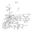
- a cord wind-up unit 10 is provided with a pair of left and right spool holding arms 14 and 16 for holding a spool 12 on the two axial sides.
- One holding arm 14 is enabled by moving means (e.g., an air cylinder) 18 to move in a direction (as indicated by arrow A of Fig. 1 ) to clamp the spool 12 and in a direction (as indicated by arrow B of Fig. 1 ) to release the spool 12 from the clamped state.
- the holding arms 14 and 16 are enabled by a take-up servomotor 20 to rotate the held spool 12 on the axis (i.e., in the direction of arrow C of Fig. 1 or backward).
- the take-up servomotor 20 is electrically connected through a servomotor driver 22 with a control device (or coordinate computing means) 24 having a computer.
- a cord winding portion (or core portion or drum) 12A of the spool 12 is constructed of a coated metal sheet 26, which has a seam (also called the "core edge") 26A formed in the axial direction of the spool 12. In the vicinity of the core edge 26A, there is formed a cord insertion hole 28.
- This cord insertion hole 28 has a center position located at a distance L1 from the closer flange 12B and at a shorter distance L2 taken along the outer circumference from the core edge 26A (Refer to Fig. 1 ).
- a cord insertion guide unit 31 for guiding the leading end of a cord (or insertion member) 30.
- This unit 31 can be moved back and forth by the not-shown drive device (e.g., an air cylinder) between a guide position, which is close to the spool 12 shown in Fig. 1 , and a standby position which is separated therefrom in the depthwise direction of the drawing of Fig. 1 .
- the not-shown drive device e.g., an air cylinder
- dispensing rollers 33 On the upper side of the cord insertion guide unit 31 at the insertion position, there are disposed a pair of dispensing rollers 33. These dispensing rollers 33 are enabled to move up and down and toward and away from each other by the not-shown moving means.
- the dispensing rollers 33 clamp the portion of the cord 30 near the leading end of the cord 30, and move downward in the clamping state to bring the cord leading end portion close to the cord insertion guide unit 31, and then rotate to let the cord leading end portion go into the cord insertion guide unit 31.
- the cord insertion guide unit 31 includes a pair of left and right guides 32 and 34. These two guides 32 and 34 are enabled by the not-shown drive means to move relatively in the direction (as indicated by arrow D of Fig. 1 ) toward each other and in the direction (as indicated by arrow E) away from each other.
- the two guides form a funnel-shaped guide hole 35 when they approach each other relatively.
- a scanning reflection type photosensor (or coordinate detecting means) 36 which is electrically connected with the control device 24.
- a color mark sensor (or auxiliary detecting means) 38 which is electrically connected with the control device 24.
- the guides 32 and 34 and the color mark sensor 38 are enabled to move along a guide rod 40 in the axial directions of the spool 12 (i.e., in the directions of arrows E and F of Fig. 1 ) by a stepping motor 42 and a gear 44 (or moving means) which are mounted on the cord insertion guide unit 31.
- the stepping motor 42 is electrically connected with the control device 24 through a motor driver 46.
- the reflection type photosensor 36 has a light emitting portion and a light receiving portion directed to a predetermined position on the extension of the cord 30 to be guided by the guide hole 35.
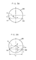
- the coordinates of the points B 1 and B2 are detected by scanning the reflection type photosensor 36 together with the cord insertion guide unit 31 in the direction of arrow E ( Fig. 3A ) along a line C which is made by joining the points B1 and B2 of a semicircle below a center line S with respect to the cod insertion hole 28.
- the cord insertion guide unit 31 approaches and abuts against the spool 12.
- the two guides 32 and 34 form the funnel-shaped guide hole 35, as has been previously described.
- the servomotor 20 is activated by a signal from the control device 24 to rotate the spool 12 in a predetermined direction, i.e., in the direction of arrow C of Fig. 1 in this embodiment. Simultaneously with this rotation, the core edge 26A of the spool 12 is detected by the color mark sensor 38 so that the spool 12 is stopped at the detected position (to determine a measurement reference position).
- the servomotor 20 is turned again by a predetermined amount ⁇ to move the cord insertion hole 28 to the correcting scan starting coordinates generally below the reflection photosensor 36.
- the predetermined amount ⁇ is so set that the leading end portion of the cord insertion guide unit 31 may come to the semicircle below (or upstream of the rotation direction C) the center line S with respect to the cord insertion hole 28.
- the stepping motor 42 is driven to scan the reflection type photosensor 36 together with the cord insertion guide unit 31 in the direction of arrow E along the line C, as shown in Fig. 3A , to thereby detect the coordinates of the points B1 and B2, and is stopped at the point B2.
- the take-up servomotor 20 is turned by a predetermined extent ⁇ on the basis of the data stored in the control device 24, so that the cord insertion hole 28 is moved to the measurement reference position to detect the coordinates the points B1 and B2 again.
- the distance y between the points B1 and B2 is determined in the control device 24 from the coordinates of the points B1 and B2.
- the control device 24 drives and controls the stepping motor 42 to move the cord insertion guide unit 31 by a distance of y/ 2 in the direction of arrow F, and drives the take-up servomotor 20 to rotate the spool 12 so that the center P of the cord insertion hole 28 may move by the distance x in the direction of arrow G of Fig. 3B .
- the leading end center of the guide hole 35 is aligned highly precisely to the center P of the cord insertion hole 28.
- the cord 30 is clamped near its leading end portion by the paired dispensing rollers 33 at the upper standby position. Then, the dispensing rollers 33 are moved downward to bring the cord leading end close to the cord guide hole 35. Next, the dispensing rollers 33 are rotated to dispense the cord 30 to a predetermined extent and insert it into the cord insertion hole 28.
- the two guides 32 and 34 leave each other to form the space for the cord 30 to pass through, and the cord insertion guide unit 31 then moves to a withdrawal position in the depth direction with respect to the paper surface in Fig. 1 .
- the spool 12 is rotated to start the winding-up of the cord 30, and the paired dispensing rollers 33 move apart from each other to release the clamped state of the cord 30 until they return to the upper standby position.
- the coordinates of the two circumferential points B1 and B2 on the straight line C in the cord insertion hole 28 are detected by the reflection type photosensor 36 and are operated by the control device 24 to determine the center coordinates of the cord insertion hole 28.
- the center coordinates of the cord insertion hole 28 can be easily determined at a low cost.
- the core edge 26A of the spool 12 for providing the measurement reference position can be stably detected by the color mark sensor 38 without being affected by a painting flaw or the like, so that the positioning can be speeded up by moving the reflection type photosensor 36 from the measurement reference position to the correcting scan starting coordinates.
- the take-up servomotor 20 is rotated to a predetermined extent ⁇ on the basis of the data stored in the control device 24, to thereby detect the coordinates of the points B1 and B2 again, so that the center of the cord insertion hole 28 can be reliably detected.
- the hole center detecting apparatus should not be limited to the cord insertion hole which is formed in the outer circumference portion of the spool but could be applied to the detection of a hole or the like formed in a flat face.
- the coordinate detecting means should not be limited to the reflection type photosensor 36 and another sensor such as an ultrasonic sensor may be used.
- the auxiliary detecting means should not be limited to the color mark sensor 38 and another sensor such as a mechanical type sensor may be used.
- the moving means should not be limited to the servomotor 20 or the stepping motor 42 and by another moving means may be used.
- the straightness measuring apparatus 110 of the present embodiment includes a measurement plate 114 for placing a cord (or an object to be measured) 112 thereon.
- a measurement plate 114 for placing a cord (or an object to be measured) 112 thereon.
- three slits 116 which are parallel in the widthwise direction (or in the direction of arrow W). These slits 116 are formed to extend from the vicinity of one widthwise end 114A to the other widthwise end 114B continuously and further to a slope portion 114C.
- Above and below those slits 116 there are transparent type optical fiber sensors (or coordinate detecting means) 120, 122 and 124 disposed such that their respective light emitting portions and light receiving portions are opposed to each other. These optical fiber sensors 120, 122 and 124 are fixed on a moving arm 126.
- This moving arm 126 is enabled to move by drive means such as a motor to move between a measurement starting position on the side of the end portion 114B of the measurement plate 114, as indicated by double-dotted lines in Fig. 5 , and a return position on the side of the end portion 114A, as indicated by solid lines in Fig. 5 .
- drive means such as a motor to move between a measurement starting position on the side of the end portion 114B of the measurement plate 114, as indicated by double-dotted lines in Fig. 5 , and a return position on the side of the end portion 114A, as indicated by solid lines in Fig. 5 .
- the moving arm 126 moves in the direction from the measurement starting position to the return position (or in the direction of arrow A of Fig. 4 )
- the coordinates of three different points in the longitudinal direction of the cord 112 can be detected by the sensors 120, 122 and 124.
- the sensors 120, 122 and 124 are electrically connected with a control device (or straightness computing means) including a computer.
- the control device 128 computes the straightness of the cord 112 from the curvature of a curve passing through the coordinates of the three points detected by the respective sensors 120, 122 and 124.
- the control device 128 is provided with a display (or display means) for displaying numerical values for the computed straightness of the cord 112.
- Dispensing pins 132 are disposed respectively at the moving arm portions opposed to the slit 116, as shown in Fig. 5 . These dispensing pins 132 are enabled by the (not-shown) drive means composed of air cylinders or the like to move between fall positions, at which they are hidden below the measurement plate 114, as indicated by double-dotted lines in Fig. 5 , and rise positions at which their leading ends protrude over the measurement plate 114, as indicated by solid lines in Fig. 5 .
- the dispensing pins 132 are moved from the fall positions to the rise positions.
- the cord 112 can be further dispensed to the slope portion 114C by the dispensing pins 132.
- the cord 112 thus dispensed, drops down along the slope portion 114C so that it is stored in the not-shown storage box.
- a straightness sampling device (simply called the “sampling device” hereinafter) for cutting the cord 112 to a predetermined sampling length and placing it on the measurement plate 114 will be described in detail with reference to Figs. 6 to 8 .
- the sampling device 140 of the present embodiment cuts a portion of the cord 112 wired in the cord take-up device or the like from the remaining portion; moves the cut portion to a placing position indicated by solid lines in Fig. 6 , through a rotation position indicated by double-dotted lines in Fig. 6 ; and places the cord sample 112 on the measurement plate 114.
- sampling unit 142 At the leading end portion of the sampling device 140, there is disposed a sampling unit 142.
- This sampling unit 142 is enabled to move back and forth in the cylinder axis directions (or in the directions of arrows C and D) by an air cylinder 144 which is mounted on an arm 143.
- the sampling unit 142 is enabled to rotate with respect to the arm 143 by a rotor 146. More specifically, the sampling unit 142 can rotate from a vertical position, as indicated by double-dotted lines of Fig. 6 , to a horizontal position (or in a state in parallel with the upper face of the measurement plate 114), in which it is inclined downward by 90 degrees (or in the direction of arrow E) and indicated by broken lines, and vice versa.
- the arm 143 is enabled by the not-shown drive means to move in a placing direction (or in the direction of arrow F of Fig. 6 ) from the position for a tilting (or rotating) motion, and vice versa.
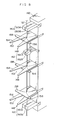
- the sampling unit 142 is provided with three guide units 148 in its longitudinal direction.
- a stationary guide 154 which has a V-shaped recess 152.
- a pair of left and right moving guides 156 and 158 are rotatably mounted on the unit base 150.
- the two guides 156 and 158 are respectively enabled by drive means composed of air cylinders or the like to move between standby positions, at which they are spaced apart, as indicated by solid lines in Fig. 7 , and guide positions at which they partially overlap each other, as indicated by double-dotted lines.
- the opposed guide faces 156A and 158A of the moving guides 156 and 158 have a substantially quarter arc shape. While the moving guides 156 and 158 are moving in the directions from the standby positions to the guide positions (or in the directions of arrows G and H), for example, the cord 112 in the vicinity of the opening of the recess 152 of the stationary guide 154 can be moved to the vicinity of a bottom portion 152A of the recess 152.
- a line of intersection P between the guide face 156A and the guide face 158A is placed in the vicinity of a position opposing the bottom portion 152A of the recess 152 in the stationary guide 154 so that the cord 112 can be positioned in the direction perpendicular to the cord axis.
- the cord 112 thus positioned is restricted relatively loosely so that it can slidably move in the cord axis direction and slidably rotate on the axis to some extent.
- thermal shearing chucks 160 At the two longitudinal ends of the sampling unit 142, as shown in Fig. 8 , there are respectively disposed thermal shearing chucks 160.
- Thermal shearing refers to the cord being cut as a result of being melted due to the high temperature of the chucks.
- Each of these thermal shearing chucks 160 is provided such that they can be opened and include thermal shearing portions 160A and 160B for pinching the cord 112 to thereby thermally shear it.
- a chuck 162 Between the upper guide unit 148 and the central guide unit 148, as shown in Fig. 8 , there is disposed a chuck 162.
- This chuck 162 includes holding portions 162A and 162B for clamping the cord 112 positioned by the guide unit 148, and is provided such that the chuck can be opened.
- the sampling unit 142 moves to the placing position, as shown by the solid lines in Fig. 6
- the chuck 162 is opened to release the clamped state of the cord 112.
- the moving guides 156 and 158 move in the directions from the guide positions to the standby positions (i.e., backwards from the direction of arrow G and the direction of arrow H) so that the cord 112 is entirely released from the hold and drops onto the measurement plate 114.
- the moving guides 156 and 158 of each guide unit 148 move from the standby positions to the guide positions so that the cord 112 is positioned.
- the positioned cord 112 is clamped by the chuck 162 and is cut to the predetermined length by the soldering chucks 160.
- the rotor 146 tilts the air cylinder 144 (and the sampling device 140) into the direction of arrow E so that the sampling device 140 is parallel to the measurement plate 114.
- the arm 143 is moved by the (not-shown) drive means from the rotation position to the placing position, as shown by the solid lines in Fig. 6 .
- the chuck 162 is opened to release the clamped state of the cord 112.
- the moving guides 156 and 158 are moved in the direction from the guide positions to the standby positions so that the cord (sample)of a predetermined length which is thus completely released, drops onto the measurement plate 114 of the straightness measuring apparatus 110.
- the moving arm 126 moves in the direction from the measurement starting position to the return position (or in the direction of arrow A of Fig. 4 ). At this time, the coordinates of the three different points in the longitudinal direction of the cord 112 are detected by the sensors 120, 122 and 124.
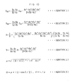
- the control device 128 determines the curvatures of the curves passing through the coordinates of the three points, as detected by the sensors 120, 122 and 124, to compute the parameters relating the straightness of the cord 112, from computing equations (1) to (6) of Fig. 10 , as will be specified in the following.
- the center coordinates (X, Y) of a curve passing through the detected coordinates A, B and C are the intersection of the aforementioned two straight lines and are determined from equations (3) and (4).
- the radius of curvature ⁇ is determined from equation(5).
- the straightness (or the curvature) H per cord length L is determined from equation (6).
- the control device 128 displays the computed straightness H of the cord 112 in numerical values on the display 130.
- the straightness of the cord 112 is computed by detecting the coordinates of the three different points in the longitudinal direction of the cord 112 with the transparent type optical fiber sensors 120, 122 and 124 and by determining the curvature of the curve passing through the coordinates of the three detected points, and the result is displayed on the display 130. Therefore, it is possible to quantitatively confirm the straightness of the cord 112 quickly and automatically. This confirmation eliminates the variation which might otherwise be caused by the manual measurements, so that the productivity can be drastically improved. It is therefore, possible to provide a steel cord for reinforcing a rubber part, or a wire for another application, in a timely manner and at a low cost.
- the coordinates of the three different points in the longitudinal direction of the cord 112 are detected by the transparent type optical fiber sensors 120, 122 and 124. Even where the cord 112 has undulations in the direction toward the transparent type optical fiber sensors 120, 122 and 124, that is, even where the cord 112 comes up from off the measurement plate 114, therefore, the straightness can be measured more precisely than with the apparatus employing the reflection type optical fiber sensors.
- Fig. 9 the results of comparing the values of the straightness of the cord 112 (having a length of 40 cm), as measured by the apparatus of the present embodiment, with the visually measured values are shown. As could be understood from Fig. 9 , the measured values of the straightness of the present embodiment and the visually measured values are substantially equal.
- the coordinate detecting means to be employed could be another sensor such as a reflection type optical fiber sensor, an ultrasonic sensor or a mechanical type sensor.
- the detecting precision can be better improved by scanning the transparent type optical fiber sensors 120, 122 and 124 several times to detect the coordinates of the three points for each scan.
- the construction may be modified such that the coordinates of four or more different points in the longitudinal direction of an object to be measured are detected by the coordinate detecting means.
- this measurement plate 114 could be provided with cord holding means such as an electromagnet or a permanent magnet.
- This residual torsion measuring apparatus basically includes: a bending unit for bending the end portion of a cord at a specified angle; and a unit for measuring and displaying the residual torsion of the bent cord.
- a base 210A of the residual torsion measuring apparatus 210 of the present embodiment is enabled by the (not-shown) drive device to move in the downward direction of a cord 212 or an object to be measured (or in the direction of arrow M of Fig. 11 ) and in the direction away from the cord 212 (or in the direction of arrow N of Fig. 11 ).
- a cord lower end portion 212A is bent at a predetermined angle ⁇ , and the cord portion above a predetermined distance (e.g., 5 m) from the cord lower end is so held by the (not-shown) holding means that the cord 212 may not rotate on the axis.
- a rotor (or drive means) 214 is disposed above the base 210A.
- This rotor 214 is enabled to rotate on a spindle 218 in the directions of arrows A and B by a motor 216 which is disposed in the base 210A.
- the flanged portion of the upper face of the rotor 214 there are disposed two rod-shaped electrodes 220 and 222 which are extended at a predetermined spacing and in parallel with the axial direction of the spindle 218. These electrodes 220 and 222 and the motor 216 are electrically connected with a control device (or operation control means) 224 composed of a computer.
- the control device 224 is provided with an operation portion 228 having a display (or display means) 226.
- switches 228A, 228B and 228C according to the kind or test standards of the cord 212.
- a cover 230 On the upper face of the rotor 214, there is disposed a cover 230.
- This cover 230 is provided with wall portions 230A and 230B which extend from the vicinities of the electrodes 220 and 222 to the rotating center of the rotor 214, so that the end portion 212A of the cord 212 may reliably contact with the electrodes 220 and 222 while being prevented from coming out of the electrodes 220 and 222.
- the diameter, the material and so on of the cord 212 are inputted from the operation portion 228, and the control device 224 changes the rotating speed of the motor 216 accordingly.
- a guide unit (or positioning means) 248 for preventing the cord 212 from moving perpendicularly to the axial direction (or the direction of arrow C).
- This guide unit 248 is enabled by the (not-shown) drive means to move integrally with the base 210A in the direction of arrow M and in the direction of arrow N of Fig. 11 ,thus moving between the positioning position shown in Fig. 11 and the standby position which is spaced apart from the cord 212.
- a stationary guide 254 which has a V-shaped recess 252.
- Two of each pair of left and right moving guides 256 and 258 are aligned above and below the two sides of the stationary guide 254.
- the two guides 256 and 258 are rotatably attached to the unit base 250 and are respectively enabled by drive means such as air cylinders or the like to move between standby positions, at which they are spaced apart, as indicated by solid lines in Fig. 12 , and guide positions at which they partially overlap each other, as indicated by double-dotted lines.
- the opposed guide faces 256A and 258A of the moving guides 256 and 258 have an approximately quarter arc shape. While the moving guides 256 and 258 are moving in the directions from the standby positions to the guide positions (or in the directions of arrows D and E), for example, the cord 212 in the vicinity of the opening of the recess 252 of the stationary guide 254 can be moved to the vicinity of a bottom portion 252A of the recess 252.
- a line of intersection P between the guide face 256A and the guide face 258A is positioned in a vicinity of a position which opposes to the bottom portion 252A of the recess 252 in the stationary guide 254 so that the cord 212 can be positioned in the direction perpendicular to the cord axis.
- the cord 212 thus positioned is restricted relatively loosely so that it can slidably move in the cord axis direction and slidably rotate on the axis to some extent.
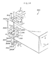
- a bending unit (or bending means) for cutting the cord 212, wired onto a cord take-up device, at its one portion and for bending its end portion 212A at a specified angle.
- the base portion 260A of a bending unit 260 of the present embodiment is enabled by the (not-shown) drive means to move in the direction toward the cord 212 (or in the direction of arrow K of Fig. 14 ) and in the direction away from the cord 212(or in the direction of arrow L of Fig. 14 ).
- This chuck 261 is enabled by the (not-shown) drive means to move in the direction (or in the direction of arrow K of Fig. 14 ) toward the cord 212 and in the direction (or in the direction of arrow L of Fig. 14 ) away from the chuck 212.
- the chuck 261 has holding portions 261A and 261B opened/closed by the (not-shown) drive means so that they can clamp the cord 212, as shown in Fig. 14 .
- thermal shearing chuck 262 is enabled by the (not-shown) drive means to move in the direction toward the cord 212 (or in the direction of arrow K of Fig. 14 ) and in the direction away from the cord 212(or in the direction of arrow L of Fig. 14 ).
- the thermal shearing chuck 262 has thermal shearing portions 262A and 262B opened/closed by the (not-shown) drive means so that they can clamp and thermally shear the cord 212, as shown in Fig. 14 .
- a guide chuck 264 On the side face of the base portion 260A, on the other hand, there is disposed a guide chuck 264.
- This guide chuck 264 is shaped by dividing a column longitudinally so that its holding portion 264A and 264B may receive the cord 212 in between as the bending unit 260 is brought close to the cord 212.
- one holding portion 264A is enabled by the (not-shown) drive means to move in the directions toward and away from the other holding portion 264B(or in the directions of arrows F and G).
- the bending unit 260 comes close to the cord 212 to take a bending position, as shown in Fig. 14 , the holding portion 264A moves toward the holding portion 262B to clamp the cord 212.
- a rotor 266, which is enabled to rotate in the directions of arrows H and J of Fig. 14 by a (not-shown) motor which is disposed as the drive means in the base portion 260A.
- cam 268 On the rotor 214, there is formed cam 268 having a variable rotation angle, and an arcuate shape when viewed in the direction of the rotating axis of the rotor 266. Also, the cam 268 has a height Y (or a protrusion in the direction of the rotating axis) which increases gradually in the rotating direction from one end portion 268A to the other end portion 268B thereby forming a slope face 268C between the two end portions.
- the end portion 268B of the cam 268 disposed on the rotor 266 abuts against the end portion 212A of the cord 212 to push and bend the end portion 212A of the cord 212 in the rotation direction (or in the direction of arrow H).
- the bending angle of the end portion 212A of the cord 212 can be changed by the rotation angle of the rotor 266.
- the chuck 261 of the bending unit 260 moves in the direction of arrow K of Fig. 14 to clamp the cord 212.
- the base portion 260A of the bending unit 260 moves in the direction of arrow K of Fig. 14 .
- the holding portion 264A of the guide chuck 264 moves in the direction of arrow F of Fig. 14 to clamp the cord 212.
- the thermal shearing chuck 262 moves in the direction of arrow K of Fig. 14 to clamp and thermally shear the cord 212.
- the thermal shearing portions 262A and 262B of thermal shearing chuck 262 separate from each other and move in the direction of arrow L of Fig. 14 away from the cord 212.
- the rotor 266 rotates by a predetermined angle in the direction of arrow H to bend the end portion 212A of the cord 212 to a predetermined angle ⁇ .
- the holding portion 264A of the guide chuck 264 moves in the direction of arrow G of Fig. 14 to release the clamped state of the cord 212.
- the rotor 266 rotates (backward) in the direction of arrow J, and the cam 268 goes from the side of the end portion 268A into the space between the straight portion 212B of the cord 212 and the rotor 266 to push the cord 212 out of the guide chuck 264.
- the base portion 260A of the bending unit 260 moves away from the cord 212 in the direction of arrow L of Fig. 14 .
- the residual torsion measuring apparatus 210 moves, for example, in the direction perpendicular to the moving direction of the chuck 261 (or in the direction of arrow M of Fig. 11 ), toward the cord 212 clamped by the chuck 261.
- the moving guides 256 and 258 of the guide unit 248 move from the standby position to the guide position to position the cord 212.
- the end portion 212A of the cord 212 is inserted into the space between the two electrodes 220 and 222, as shown in Fig. 11 .
- the rotor 214 is rotated in the direction of arrow B from the position indicated by the double-dotted lines, as shown in Fig. 13A , to bring one electrode 222 to abut against the end portion 212A of the cord 212.
- an electric signal is inputted to the control device 224 so that the control device 224 stops the rotation of the rotor 214 and stores a detection angle ⁇ 1.
- the holding portions 261A and 261B of the chuck 261 shown in Fig. 11 separate from each other, and move in the direction of arrow L of Fig. 11 to leave the cord 212.
- the residual torsion of the cord 212 turns the end portion 212A of the cord 212 in the direction of arrow R from the position indicated by double-dotted lines, as shown in Fig. 13B , to abut against the other electrode 220.
- control device 224 rotates the rotor 214 in the direction of arrow B. Before the rotation angle of the rotor 214 reaches a predetermined value, as shown in Fig. 13C , the residual torsion of the cord 212 holds the end portion 212A of the cord 212 to abut against the electrode 220.
- the end portion 212A of the cord 212 leaves the electrode 220 and once again abuts against the electrode 222.
- the electric signal at this time is inputted to the control device 224 so that the control device 224 stops the rotation of the rotor 214 and stores a detection angle ⁇ 2.
- the control device 224 computes the residual torsion of the cord 212 from the difference between the detection angle ⁇ 1 and the detection angle ⁇ 2 and displays the computed residual torsion in the display 226 of the operation portion 228.
- the residual torsion measuring apparatus 210 of the present embodiment can measure the residual torsion more precisely than when measured by an inspector and can improve the productivity. Further, by combining the apparatus 210 with other automated devices, moreover, the productivity can be enhanced to provide a steel cord for reinforcing a rubber part or a wire for another application at a low cost.
- the residual torsion which when manually measured had a precision of a quarter to a half rotation, can be measured more precisely than the measurement by the inspector since the residual torsion of the cord 212 is measured using the rotation angle of the rotor 214.
- the two electrodes 220 and 222 disposed across the end portion 212A of the cord 212 are employed to compute the residual torsion from the rotation angle ⁇ 1 of the rotor 214 at the instant when the end portion 212A of the cord 212 contacts with the electrode 222 and the rotation angle ⁇ 2 of the rotor 214 at the instant when the end portion 212A of the cord 212 contact with the electrode 222.
- the electrodes 220 and 222 are formed in a rod shape, and there is provided the cover 230 for ensuring contact of the end portion 212A of the cord 212 with the electrodes 220 and 222 so that it is difficult for the electrodes 220 and 222 to separate from the end portion 212A of the cord 212 during the measurement. As a result, it is possible to ensure that the measurement of the residual torsion is appropriately carried out.
- the rotating speed of the rotor 214 can be made to change in accordance with the diameter, material and so on of the cord 212.
- the rotating speed of the rotor 214 By setting the optimum rotating speed of the rotor 214 according to the diameter, material and so on of the cord 212, it is possible to ensure the measurement of the residual torsion and to shorten the measurement time.
- the cord 212 By attaching the guide unit 248 to the upper portion of the residual torsion measuring apparatus 210, the cord 212 can be prevented from being affected by the straightness of the cord 212 and from moving during the measurement in the direction perpendicular to the axial direction, so that the measurement precision of the residual torsion can be better improved.
- the end portion 212A of the cord 212 can be bent to the specified angle by the bending unit 260 before the start of measurement so that the measurement preparations can be automated.
- Fig. 16 is a graph plotting the results (by symbol O) which were obtained by applying a predetermined torsion to the cord 212 of 5 m and by measuring the torsion twice with the residual torsion measuring apparatus 210 of the present embodiment. From this graph, it is found that the values of the residual torsion measured in the present embodiment were hardly different from the applied torsion.
- the present invention could be constructed such that the residual torsion measuring apparatus 210 has only one electrode 220 or 222.
- the operation portion 228 may be modified into another construction such as a touch panel, and the display means should not be limited to the display 226 but another display means such as a digital meter may be used. Further, the bending unit 260 may also be provided with the guide unit 248.
- a hole center detecting apparatus comprising:
- the apparatus further comprising:
- the apparatus further comprising:
- said moving means moves the object in a manner to correspond to said predetermined coordinate relation at the time of detecting said mark so as to form the points of intersection between the inner circumference of said hole and said virtual straight line.
- said moving means repeats the movement of the object until said intersection points are formed.
- said object is a rotary type spool, and wherein said insertion member is a cord to be wound on a spool outer circumference.
- said mark is a seam on the outer circumference of the object.
- a straightness measuring apparatus comprising:
- said coordinate detecting means includes a transparent type optical fiber sensor.
- sampling means for cutting the object to a predetermined length.
- the object is a cord.
- an apparatus for measuring the residual torsion of an object to be measured the object having a straight portion and a terminal portion bent at a specified angle from one end of said straight portion, and comprising:
- said detection means includes at least one electrode disposed to abut against the end portion of the object.
- the detection means includes two electrodes disposed to abut against the end portion of the object and spaced from each other so that the end portion of the object is positioned therebetween, and wherein the two electrodes are extended in parallel with the axial direction of the straight portion of the object.
- a guide unit for controlling the free movement of the object in a direction which intersects the axial direction.
Landscapes
- Length Measuring Devices With Unspecified Measuring Means (AREA)
- A Measuring Device Byusing Mechanical Method (AREA)
- Tyre Moulding (AREA)
Applications Claiming Priority (4)
| Application Number | Priority Date | Filing Date | Title |
|---|---|---|---|
| JP2000285821A JP2002096973A (ja) | 2000-09-20 | 2000-09-20 | 穴中心検出装置 |
| JP2000285823A JP4278848B2 (ja) | 2000-09-20 | 2000-09-20 | 残留トーション測定装置 |
| JP2000285822A JP4713719B2 (ja) | 2000-09-20 | 2000-09-20 | 真直性測定装置 |
| EP01307931A EP1191304B1 (fr) | 2000-09-20 | 2001-09-18 | Dispositif de détection de centres de trous, dispositif de mesure de la rectitude et dispositif de mesure de la torsion résiduelle |
Related Parent Applications (1)
| Application Number | Title | Priority Date | Filing Date |
|---|---|---|---|
| EP01307931.4 Division | 2001-09-18 |
Publications (2)
| Publication Number | Publication Date |
|---|---|
| EP2293009A1 true EP2293009A1 (fr) | 2011-03-09 |
| EP2293009B1 EP2293009B1 (fr) | 2012-05-09 |
Family
ID=27344683
Family Applications (2)
| Application Number | Title | Priority Date | Filing Date |
|---|---|---|---|
| EP10075693A Expired - Lifetime EP2293009B1 (fr) | 2000-09-20 | 2001-09-18 | Dispositif de mesure de la torsion résiduelle |
| EP01307931A Expired - Lifetime EP1191304B1 (fr) | 2000-09-20 | 2001-09-18 | Dispositif de détection de centres de trous, dispositif de mesure de la rectitude et dispositif de mesure de la torsion résiduelle |
Family Applications After (1)
| Application Number | Title | Priority Date | Filing Date |
|---|---|---|---|
| EP01307931A Expired - Lifetime EP1191304B1 (fr) | 2000-09-20 | 2001-09-18 | Dispositif de détection de centres de trous, dispositif de mesure de la rectitude et dispositif de mesure de la torsion résiduelle |
Country Status (3)
| Country | Link |
|---|---|
| US (3) | US6578280B2 (fr) |
| EP (2) | EP2293009B1 (fr) |
| ES (2) | ES2374265T3 (fr) |
Families Citing this family (29)
| Publication number | Priority date | Publication date | Assignee | Title |
|---|---|---|---|---|
| US6640458B2 (en) * | 2002-03-25 | 2003-11-04 | Btm Corporation | End arm effector set-up |
| US20050262911A1 (en) * | 2004-02-06 | 2005-12-01 | Harry Dankowicz | Computer-aided three-dimensional bending of spinal rod implants, other surgical implants and other articles, systems for three-dimensional shaping, and apparatuses therefor |
| WO2006063324A1 (fr) * | 2004-12-10 | 2006-06-15 | Virginia Tech Intellectual Properties, Inc. | Systemes et procedes pour la caracterisation multidimensionnelle et la classification d'une forme de colonne vertebrale |
| US7957831B2 (en) * | 2008-04-04 | 2011-06-07 | Isaacs Robert E | System and device for designing and forming a surgical implant |
| US8549888B2 (en) | 2008-04-04 | 2013-10-08 | Nuvasive, Inc. | System and device for designing and forming a surgical implant |
| US11207132B2 (en) | 2012-03-12 | 2021-12-28 | Nuvasive, Inc. | Systems and methods for performing spinal surgery |
| US9848922B2 (en) | 2013-10-09 | 2017-12-26 | Nuvasive, Inc. | Systems and methods for performing spine surgery |
| CN105611884B (zh) | 2013-10-09 | 2019-06-28 | 纽文思公司 | 在手术脊椎程序期间术中设计并评定脊椎畸形矫正的系统 |
| AU2015277134B2 (en) | 2014-06-17 | 2019-02-28 | Nuvasive, Inc. | Systems and methods for planning, performing, and assessing spinal correction during surgery |
| CN104057298B (zh) * | 2014-06-30 | 2017-08-08 | 日立电梯电机(广州)有限公司 | 寻孔装置 |
| EP3189318B1 (fr) * | 2014-09-02 | 2018-12-26 | NV Bekaert SA | Appareil et procédé de mesure de torsions résiduelles |
| US9913669B1 (en) | 2014-10-17 | 2018-03-13 | Nuvasive, Inc. | Systems and methods for performing spine surgery |
| CN104535237B (zh) * | 2014-12-31 | 2017-07-28 | 苏州哈工维实自动化科技有限公司 | 一种钢帘线残余扭转检测设备 |
| US10390884B2 (en) | 2015-06-30 | 2019-08-27 | DePuy Synthes Products, Inc. | Methods and templates for shaping patient-specific anatomical-fixation implants |
| CN106053258B (zh) * | 2016-08-01 | 2019-04-09 | 江苏胜达科技有限公司 | 钢丝残余扭转值的检测装置及检测方法 |
| CN106840068B (zh) * | 2017-01-19 | 2023-10-03 | 深圳新智远科技有限公司 | 一种钢帘线的检测系统 |
| CN108088383B (zh) * | 2017-12-05 | 2019-06-25 | 武汉理工大学 | 一种应用于起重机械的摄影测量算法 |
| TWI658880B (zh) * | 2018-01-23 | 2019-05-11 | 正新橡膠工業股份有限公司 | 輪胎鋼絲環帶之角度及間距測量方法 |
| CN109489700B (zh) * | 2018-11-09 | 2021-02-12 | 重庆云天智能技术有限公司 | 一种人工智能化用具有安装固定的检测平台 |
| CN109323726A (zh) * | 2018-11-09 | 2019-02-12 | 北京航天智造科技发展有限公司 | 用于检测钢帘线残余扭转的自动化生产线 |
| TWI693417B (zh) * | 2018-12-12 | 2020-05-11 | 裕群精密科技有限公司 | 電子線夾測試機 |
| JP6836613B2 (ja) * | 2019-03-08 | 2021-03-03 | トクセン工業株式会社 | 線材巻取り装置および線材巻取り方法 |
| CN110864616B (zh) * | 2019-12-04 | 2024-12-17 | 镇江耐丝新型材料有限公司 | 一种钢帘线计米系统及故障判断方法 |
| CN111664785A (zh) * | 2020-07-07 | 2020-09-15 | 宁波赛乐福板材成型技术有限公司 | 调试超长设备直线度的装置及其方法 |
| DE102020127164B3 (de) * | 2020-10-15 | 2021-07-15 | Jenoptik Industrial Metrology Germany Gmbh | Radialkraft-Vorrichtung für ein Konturmessgerät und Messsystem |
| US12576591B2 (en) * | 2022-12-29 | 2026-03-17 | Jf Polymers (Suzhou) Co., Ltd. | Automatic filament ending device |
| CN116124057A (zh) * | 2023-04-13 | 2023-05-16 | 陕西深孔智越科技有限公司 | 直驱式深孔加工检测装置及测量方法 |
| CN117049293B (zh) * | 2023-10-12 | 2023-12-12 | 深圳市睿拓新科技有限公司 | 一种公路施工建设用测量放线设备 |
| CN119648794B (zh) * | 2024-12-06 | 2025-10-31 | 珠海创智科技有限公司 | 一种基于Python的卷轴识别算法 |
Citations (3)
| Publication number | Priority date | Publication date | Assignee | Title |
|---|---|---|---|---|
| EP0328272A2 (fr) * | 1988-02-10 | 1989-08-16 | Amcor Limited | Méthode de mesure de rigidité en cisaillement |
| US5456122A (en) * | 1994-10-13 | 1995-10-10 | The United States Of America As Represented By The Secretary Of The Navy | Cable load transducer |
| US5460052A (en) * | 1994-07-28 | 1995-10-24 | University Of Massachusetts Lowell | Apparatus and method for measuring composite interface properties |
Family Cites Families (36)
| Publication number | Priority date | Publication date | Assignee | Title |
|---|---|---|---|---|
| US3110112A (en) * | 1960-03-02 | 1963-11-12 | John E Dalgleish | Method and apparatus for gauging articles |
| GB1076253A (en) * | 1962-12-19 | 1967-07-19 | Rank Organisation Ltd | Method and apparatus for assessing the co-ordinates of the centre of a roughly circular form relative to a fixed axis |
| GB1199328A (en) * | 1966-09-07 | 1970-07-22 | Yawata Iron & Steel Co | Method of Measuring the Surface Waviness of Sheet or Strip Material |
| SE353958B (fr) * | 1967-04-19 | 1973-02-19 | Asea Ab | |
| US3620071A (en) * | 1970-06-05 | 1971-11-16 | Rohm & Haas | Testing materials for resilience and stiffness |
| SE371630B (fr) * | 1974-01-25 | 1974-11-25 | Skaltek Ab | |
| JPS5517655B2 (fr) * | 1974-02-25 | 1980-05-13 | ||
| ES440899A1 (es) * | 1974-09-19 | 1977-06-16 | Standard Pressed Steel Co | Un metodo de apretar un organo de sujecion. |
| IT1047307B (it) * | 1974-09-24 | 1980-09-10 | Rank Organisation Ltd | Strumento per la misurazione di superfici |
| JPS5617601B2 (fr) * | 1974-11-27 | 1981-04-23 | ||
| SE412286B (sv) * | 1978-07-10 | 1980-02-25 | Saab Scania Ab | Sett och anordning for fotoelektrisk avmetning av breder eller liknande geometriskt obestemda foremal |
| US4386344A (en) * | 1981-04-16 | 1983-05-31 | Vecchiatto Charles L | Electronic edge and center locator and method of using same |
| US4652744A (en) * | 1982-04-14 | 1987-03-24 | The Board Of Trustees Of The Leland Stanford Junior University | Fiber optic sensor for detecting very small displacements of a surface |
| US4589082A (en) * | 1983-01-17 | 1986-05-13 | Westinghouse Electric Corp. | Nuclear fuel rod straightness measuring system and method |
| SU1087368A1 (ru) * | 1983-02-18 | 1984-04-23 | Научно-Исследовательский Ордена Ленина Институт Шинной Промышленности | Диагонально-резательна машина |
| JPS60256003A (ja) * | 1984-06-01 | 1985-12-17 | Furukawa Electric Co Ltd:The | 金属条の走間曲がり測定装置 |
| JPS6171307A (ja) * | 1984-09-17 | 1986-04-12 | Nippon Steel Corp | 管棒状体の曲り測定方法 |
| US4647208A (en) * | 1985-07-22 | 1987-03-03 | Perceptron, Inc. | Method for spatial measurement of holes |
| JPH067073B2 (ja) * | 1986-04-21 | 1994-01-26 | 株式会社日立製作所 | トルク検出方法及びその検出装置 |
| FI88282C (fi) * | 1990-11-28 | 1993-04-26 | Kone Oy | Utrustning foer kontroll av rakheten hos hissgejder |
| JP2949528B2 (ja) * | 1991-03-13 | 1999-09-13 | 東京エレクトロン株式会社 | ウエハの中心位置検出方法及びその装置 |
| US5205046A (en) * | 1991-06-05 | 1993-04-27 | Ford Motor Company | Method for measuring surface waviness |
| JPH05113315A (ja) * | 1991-10-22 | 1993-05-07 | Hitachi Ltd | 円形画像データの中心位置検出方法 |
| JPH05180642A (ja) * | 1991-12-28 | 1993-07-23 | Asahi Glass Co Ltd | 平面物体の真直度測定機 |
| US5460333A (en) * | 1992-07-21 | 1995-10-24 | N.V. Bekaert S.A. | Method apparatus and spool for automated winding |
| GB2276446B (en) * | 1993-03-26 | 1996-07-03 | Honda Motor Co Ltd | Method of measuring the position of a hole |
| FR2705145B1 (fr) * | 1993-05-10 | 1995-08-04 | Exa Ingenierie | Dispositif de mesure de rectitude. |
| JPH07225843A (ja) * | 1994-02-09 | 1995-08-22 | Matsushita Electric Ind Co Ltd | 円中心位置測定方法 |
| JPH08159750A (ja) * | 1994-11-30 | 1996-06-21 | Sumitomo Rubber Ind Ltd | タイヤ測定装置 |
| SE504021C2 (sv) * | 1995-01-26 | 1996-10-21 | Windak Ab | Anordning för automatisk upptagning av kabel, vajer lina eller dylikt |
| US5639506A (en) * | 1996-02-08 | 1997-06-17 | United States Surgical Corporation | Rotary suture cutting apparatus and method of use |
| US5886775A (en) * | 1997-03-12 | 1999-03-23 | M+Ind | Noncontact digitizing imaging system |
| CA2242179C (fr) * | 1997-07-07 | 2006-10-03 | Takao Shibayama | Methode et appareil servant a determiner la position d'un orifice |
| DE19918699B4 (de) * | 1999-04-26 | 2008-03-27 | Betriebsforschungsinstitut VDEh - Institut für angewandte Forschung GmbH | Meßrolle zum Feststellen von Planheitsabweichungen |
| US6668626B2 (en) * | 2001-03-01 | 2003-12-30 | Abb Ab | System and a method for measuring and determining flatness |
| US6711828B2 (en) * | 2001-12-05 | 2004-03-30 | First Data Corporation | Warpage measurement system and methods |
-
2001
- 2001-09-18 EP EP10075693A patent/EP2293009B1/fr not_active Expired - Lifetime
- 2001-09-18 ES ES01307931T patent/ES2374265T3/es not_active Expired - Lifetime
- 2001-09-18 ES ES10075693T patent/ES2383501T3/es not_active Expired - Lifetime
- 2001-09-18 EP EP01307931A patent/EP1191304B1/fr not_active Expired - Lifetime
- 2001-09-19 US US09/955,172 patent/US6578280B2/en not_active Expired - Lifetime
-
2003
- 2003-04-28 US US10/423,990 patent/US6752025B2/en not_active Expired - Lifetime
- 2003-04-28 US US10/423,973 patent/US7013573B2/en not_active Expired - Lifetime
Patent Citations (3)
| Publication number | Priority date | Publication date | Assignee | Title |
|---|---|---|---|---|
| EP0328272A2 (fr) * | 1988-02-10 | 1989-08-16 | Amcor Limited | Méthode de mesure de rigidité en cisaillement |
| US5460052A (en) * | 1994-07-28 | 1995-10-24 | University Of Massachusetts Lowell | Apparatus and method for measuring composite interface properties |
| US5456122A (en) * | 1994-10-13 | 1995-10-10 | The United States Of America As Represented By The Secretary Of The Navy | Cable load transducer |
Also Published As
| Publication number | Publication date |
|---|---|
| US20030200668A1 (en) | 2003-10-30 |
| EP1191304A2 (fr) | 2002-03-27 |
| US7013573B2 (en) | 2006-03-21 |
| US20020038516A1 (en) | 2002-04-04 |
| EP2293009B1 (fr) | 2012-05-09 |
| US20030204964A1 (en) | 2003-11-06 |
| EP1191304B1 (fr) | 2011-11-16 |
| EP1191304A3 (fr) | 2006-04-12 |
| ES2374265T3 (es) | 2012-02-15 |
| ES2383501T3 (es) | 2012-06-21 |
| US6752025B2 (en) | 2004-06-22 |
| US6578280B2 (en) | 2003-06-17 |
Similar Documents
| Publication | Publication Date | Title |
|---|---|---|
| EP2293009B1 (fr) | Dispositif de mesure de la torsion résiduelle | |
| ES3056635T3 (en) | System for determining cause of electrode connection and roll map generation system using same | |
| US6400146B1 (en) | Sensor head for ACFM based crack detection | |
| EP2717042B1 (fr) | Procédé de mesure de propriété magnétique et dispositif de mesure de propriété magnétique | |
| US20250146814A1 (en) | Measuring unit, and measuring method of measuring straightened wire-shaped or tubular material | |
| US5029502A (en) | Method and apparatus for cutting wire-embedded member for use in tire | |
| JP2007205826A (ja) | ワイヤロープの探傷装置 | |
| JP4091121B2 (ja) | 曲げ加工センタ、及び金属シート材部分を曲げ加工センタの曲げ加工ユニットに導入する方法 | |
| EP1995012A2 (fr) | Procédé pour la détermination d'un point support de fil dans une machine de décharge électrique à coupe-pâte et élément de mesure pour le réaliser | |
| JP2002104736A (ja) | 線状材自動巻取り装置 | |
| JP4713719B2 (ja) | 真直性測定装置 | |
| EP0610758A2 (fr) | Procédé et système pour la détermination des dimensions et de la position d'une tête de cylindre | |
| JP4278848B2 (ja) | 残留トーション測定装置 | |
| JPH06307845A (ja) | ロールアライメント測定方法 | |
| JP2007333519A (ja) | ホース検尺装置 | |
| CN112105497B (zh) | 用于分配胎圈芯线的具有方位角控制的系统和方法 | |
| JP4210789B2 (ja) | ボビン検査装置及びこれを用いた検査方法 | |
| EP0702779B1 (fr) | Systeme comprenant un indicateur de position et procede d'exploration d'une surface a la main a l'aide d'un detecteur | |
| JP2006349407A (ja) | ワイヤ位置検出方法及びその装置 | |
| JP2025139054A (ja) | 巻線装置、及び、巻線方法 | |
| CN120446599A (zh) | 一种元器件插入损耗测试方法及系统 | |
| JPH0730190Y2 (ja) | コイリングマシン | |
| JP2000055604A (ja) | ケーブルの条長確認方法 | |
| JPH10160449A (ja) | 管の主要寸法測定装置 | |
| JPH05126800A (ja) | チユーブ内面検査装置 |
Legal Events
| Date | Code | Title | Description |
|---|---|---|---|
| PUAI | Public reference made under article 153(3) epc to a published international application that has entered the european phase |
Free format text: ORIGINAL CODE: 0009012 |
|
| 17P | Request for examination filed |
Effective date: 20101026 |
|
| AC | Divisional application: reference to earlier application |
Ref document number: 1191304 Country of ref document: EP Kind code of ref document: P |
|
| AK | Designated contracting states |
Kind code of ref document: A1 Designated state(s): DE ES FR GB IT |
|
| GRAP | Despatch of communication of intention to grant a patent |
Free format text: ORIGINAL CODE: EPIDOSNIGR1 |
|
| GRAS | Grant fee paid |
Free format text: ORIGINAL CODE: EPIDOSNIGR3 |
|
| GRAA | (expected) grant |
Free format text: ORIGINAL CODE: 0009210 |
|
| AC | Divisional application: reference to earlier application |
Ref document number: 1191304 Country of ref document: EP Kind code of ref document: P |
|
| AK | Designated contracting states |
Kind code of ref document: B1 Designated state(s): DE ES FR GB IT |
|
| REG | Reference to a national code |
Ref country code: GB Ref legal event code: FG4D |
|
| REG | Reference to a national code |
Ref country code: ES Ref legal event code: FG2A Ref document number: 2383501 Country of ref document: ES Kind code of ref document: T3 Effective date: 20120621 |
|
| REG | Reference to a national code |
Ref country code: DE Ref legal event code: R096 Ref document number: 60146564 Country of ref document: DE Effective date: 20120705 |
|
| PLBE | No opposition filed within time limit |
Free format text: ORIGINAL CODE: 0009261 |
|
| STAA | Information on the status of an ep patent application or granted ep patent |
Free format text: STATUS: NO OPPOSITION FILED WITHIN TIME LIMIT |
|
| 26N | No opposition filed |
Effective date: 20130212 |
|
| REG | Reference to a national code |
Ref country code: DE Ref legal event code: R097 Ref document number: 60146564 Country of ref document: DE Effective date: 20130212 |
|
| PGFP | Annual fee paid to national office [announced via postgrant information from national office to epo] |
Ref country code: DE Payment date: 20130919 Year of fee payment: 13 Ref country code: ES Payment date: 20130927 Year of fee payment: 13 |
|
| PGFP | Annual fee paid to national office [announced via postgrant information from national office to epo] |
Ref country code: GB Payment date: 20130919 Year of fee payment: 13 Ref country code: FR Payment date: 20130919 Year of fee payment: 13 |
|
| PGFP | Annual fee paid to national office [announced via postgrant information from national office to epo] |
Ref country code: IT Payment date: 20130930 Year of fee payment: 13 |
|
| REG | Reference to a national code |
Ref country code: FR Ref legal event code: CA Effective date: 20140812 |
|
| REG | Reference to a national code |
Ref country code: DE Ref legal event code: R119 Ref document number: 60146564 Country of ref document: DE |
|
| GBPC | Gb: european patent ceased through non-payment of renewal fee |
Effective date: 20140918 |
|
| REG | Reference to a national code |
Ref country code: DE Ref legal event code: R119 Ref document number: 60146564 Country of ref document: DE Effective date: 20150401 |
|
| REG | Reference to a national code |
Ref country code: FR Ref legal event code: ST Effective date: 20150529 |
|
| PG25 | Lapsed in a contracting state [announced via postgrant information from national office to epo] |
Ref country code: GB Free format text: LAPSE BECAUSE OF NON-PAYMENT OF DUE FEES Effective date: 20140918 Ref country code: DE Free format text: LAPSE BECAUSE OF NON-PAYMENT OF DUE FEES Effective date: 20150401 |
|
| PG25 | Lapsed in a contracting state [announced via postgrant information from national office to epo] |
Ref country code: FR Free format text: LAPSE BECAUSE OF NON-PAYMENT OF DUE FEES Effective date: 20140930 Ref country code: IT Free format text: LAPSE BECAUSE OF NON-PAYMENT OF DUE FEES Effective date: 20140918 |
|
| REG | Reference to a national code |
Ref country code: ES Ref legal event code: FD2A Effective date: 20151029 |
|
| PG25 | Lapsed in a contracting state [announced via postgrant information from national office to epo] |
Ref country code: ES Free format text: LAPSE BECAUSE OF NON-PAYMENT OF DUE FEES Effective date: 20140919 |