EP2293085B1 - Appareil de mesure - Google Patents
Appareil de mesure Download PDFInfo
- Publication number
- EP2293085B1 EP2293085B1 EP10009267.5A EP10009267A EP2293085B1 EP 2293085 B1 EP2293085 B1 EP 2293085B1 EP 10009267 A EP10009267 A EP 10009267A EP 2293085 B1 EP2293085 B1 EP 2293085B1
- Authority
- EP
- European Patent Office
- Prior art keywords
- locking unit
- measuring
- measuring instrument
- instrument according
- locking
- Prior art date
- Legal status (The legal status is an assumption and is not a legal conclusion. Google has not performed a legal analysis and makes no representation as to the accuracy of the status listed.)
- Not-in-force
Links
- 238000012360 testing method Methods 0.000 description 16
- 230000000903 blocking effect Effects 0.000 description 14
- 238000004146 energy storage Methods 0.000 description 3
- 238000010276 construction Methods 0.000 description 2
- 238000005516 engineering process Methods 0.000 description 2
- 238000003780 insertion Methods 0.000 description 2
- 230000037431 insertion Effects 0.000 description 2
- 238000005259 measurement Methods 0.000 description 2
- 238000011161 development Methods 0.000 description 1
- 230000018109 developmental process Effects 0.000 description 1
- 230000002349 favourable effect Effects 0.000 description 1
- 210000003746 feather Anatomy 0.000 description 1
- 238000002347 injection Methods 0.000 description 1
- 239000007924 injection Substances 0.000 description 1
- 230000003993 interaction Effects 0.000 description 1
- 238000004519 manufacturing process Methods 0.000 description 1
- 239000000155 melt Substances 0.000 description 1
- 238000000034 method Methods 0.000 description 1
Images
Classifications
-
- G—PHYSICS
- G01—MEASURING; TESTING
- G01R—MEASURING ELECTRIC VARIABLES; MEASURING MAGNETIC VARIABLES
- G01R1/00—Details of instruments or arrangements of the types included in groups G01R5/00 - G01R13/00 and G01R31/00
- G01R1/02—General constructional details
- G01R1/04—Housings; Supporting members; Arrangements of terminals
-
- G—PHYSICS
- G01—MEASURING; TESTING
- G01D—MEASURING NOT SPECIALLY ADAPTED FOR A SPECIFIC VARIABLE; ARRANGEMENTS FOR MEASURING TWO OR MORE VARIABLES NOT COVERED IN A SINGLE OTHER SUBCLASS; TARIFF METERING APPARATUS; MEASURING OR TESTING NOT OTHERWISE PROVIDED FOR
- G01D11/00—Component parts of measuring arrangements not specially adapted for a specific variable
- G01D11/24—Housings ; Casings for instruments
-
- G—PHYSICS
- G01—MEASURING; TESTING
- G01R—MEASURING ELECTRIC VARIABLES; MEASURING MAGNETIC VARIABLES
- G01R15/00—Details of measuring arrangements of the types provided for in groups G01R17/00 - G01R29/00, G01R33/00 - G01R33/26 or G01R35/00
- G01R15/12—Circuits for multi-testers, i.e. multimeters, e.g. for measuring voltage, current, or impedance at will
- G01R15/125—Circuits for multi-testers, i.e. multimeters, e.g. for measuring voltage, current, or impedance at will for digital multimeters
-
- G—PHYSICS
- G01—MEASURING; TESTING
- G01R—MEASURING ELECTRIC VARIABLES; MEASURING MAGNETIC VARIABLES
- G01R19/00—Arrangements for measuring currents or voltages or for indicating presence or sign thereof
- G01R19/25—Arrangements for measuring currents or voltages or for indicating presence or sign thereof using digital measurement techniques
- G01R19/2503—Arrangements for measuring currents or voltages or for indicating presence or sign thereof using digital measurement techniques for measuring voltage only, e.g. digital volt meters (DVM's)
-
- H—ELECTRICITY
- H01—ELECTRIC ELEMENTS
- H01M—PROCESSES OR MEANS, e.g. BATTERIES, FOR THE DIRECT CONVERSION OF CHEMICAL ENERGY INTO ELECTRICAL ENERGY
- H01M50/00—Constructional details or processes of manufacture of the non-active parts of electrochemical cells other than fuel cells, e.g. hybrid cells
- H01M50/20—Mountings; Secondary casings or frames; Racks, modules or packs; Suspension devices; Shock absorbers; Transport or carrying devices; Holders
- H01M50/204—Racks, modules or packs for multiple batteries or multiple cells
- H01M50/207—Racks, modules or packs for multiple batteries or multiple cells characterised by their shape
- H01M50/213—Racks, modules or packs for multiple batteries or multiple cells characterised by their shape adapted for cells having curved cross-section, e.g. round or elliptic
-
- G—PHYSICS
- G01—MEASURING; TESTING
- G01R—MEASURING ELECTRIC VARIABLES; MEASURING MAGNETIC VARIABLES
- G01R1/00—Details of instruments or arrangements of the types included in groups G01R5/00 - G01R13/00 and G01R31/00
- G01R1/02—General constructional details
- G01R1/04—Housings; Supporting members; Arrangements of terminals
- G01R1/0408—Test fixtures or contact fields; Connectors or connecting adaptors; Test clips; Test sockets
-
- Y—GENERAL TAGGING OF NEW TECHNOLOGICAL DEVELOPMENTS; GENERAL TAGGING OF CROSS-SECTIONAL TECHNOLOGIES SPANNING OVER SEVERAL SECTIONS OF THE IPC; TECHNICAL SUBJECTS COVERED BY FORMER USPC CROSS-REFERENCE ART COLLECTIONS [XRACs] AND DIGESTS
- Y02—TECHNOLOGIES OR APPLICATIONS FOR MITIGATION OR ADAPTATION AGAINST CLIMATE CHANGE
- Y02E—REDUCTION OF GREENHOUSE GAS [GHG] EMISSIONS, RELATED TO ENERGY GENERATION, TRANSMISSION OR DISTRIBUTION
- Y02E60/00—Enabling technologies; Technologies with a potential or indirect contribution to GHG emissions mitigation
- Y02E60/10—Energy storage using batteries
Definitions
- the invention relates to a measuring instrument according to the preamble of claim 1.
- Measuring instruments such as digital multimeters
- such measuring instruments require a battery, which must be replaced from time to time.
- a fuse is provided, which melts in case of overload of the instrument and then also must be replaced.
- Such interchangeable elements are usually housed in the measuring device in each case in a compartment which can be closed with a lid. If, during the course of a measurement, it becomes necessary to replace the battery or fuse, the measuring instrument should first be disconnected from the DUT for safety reasons. If this is forgotten and the meter is under tension, then you may get an electric shock during the replacement process.
- the DE 44 38 239 Cl describes a battery powered meter.
- the receptacle for the batteries is covered by an attachable to the device housing attachable adapter housing. Both the device housing and the adapter housing in the assembled state have aligned openings that allow insertion and removal of test leads. Test leads can therefore only be removed when the adapter housing is connected to the device housing.
- a measuring device is known in which openings are provided for connecting test leads in the device housing, which are aligned with provided in a removable battery compartment cover openings. Consequently, the battery compartment cover can only be removed if the test leads have been previously removed.
- the invention has for its object to provide a measuring instrument available, which avoids the above-mentioned disadvantages.
- the invention offers security in that access to the compartments for battery or fuse is only released by a movable blocking member when no measuring line is connected to the measuring instrument.
- This locking member is according to the invention either only the sockets of the measuring instrument for the test leads, but not the covers for the battery compartment or the fuse free or vice versa.
- the second position of the locking member so the position at which the test socket is locked, by means of an energy storage, such as a spring accumulator, biased.
- the blocking of the respective measuring bushing is effected by a blocking element of the blocking element, which engages in the blocking position in the annular plug-in space of the measuring bushing.
- the blocking element preferably extends as far as the end of the measuring bushing or even beyond it, in order to ensure that no contact with a plug is possible when the measuring instrument is locked.
- the locking member is designed as a rocker and therefore performs a pivoting movement.
- the cover has a first ramp which cooperates with a first stop of the locking member. In this case, the blocking element moves away from the measuring socket and releases the insertion space as a result.
- the cover has a second ramp which cooperates with a second stop of the locking member. The second ramp inhibits the movement of the cover with plugged plug. This prevents the cover from opening when the plug is plugged in. However, if the plug is removed, causes the energy storage of the Blocking member blocking the Aufsteckraums the test socket by pivoting movement of the locking member.
- the locking member is mounted on two sides in the interior of the housing of the measuring instrument, for example by laterally molded pivot pin. Appropriately, these are, as viewed in the longitudinal direction of the locking member, approximately in the region of the pivot pin.
- the locking member preferably comprises a plurality of locking elements, each locking element is associated with a separate measuring socket. This ensures that the cover can not be opened even if, for example, only one plug is still on a test socket.
- the locking member is formed in one piece, for example as an injection-molded part.
- the locking member allows the cover member to be located on the opposite side of the measuring instrument from the measuring sockets. This results in the advantage that large-area displays can be arranged on the side of the measuring sockets.
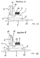
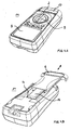
- FIG Fig. 4A denotes the measuring instrument according to the invention in its entirety. It comprises a single-part or multi-part housing 10, a large-area display 8, a rotary handle 9 for switching over the measuring range and a plurality of measuring sockets 2 for receiving measuring lines which are inserted into the measuring sockets via corresponding plugs. In the field of measuring sockets 2 circular recesses are provided in the housing 10. In addition, individual (in Fig. 4A not shown) keys can be provided.
- a receptacle 4 for a replaceable component in the present case, for example, two rod-shaped batteries 16.
- the receptacle 4 is closed by the longitudinally displaceable cover 6.
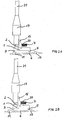
- Fig. 1A shows the claimed by the present invention fuse the measuring sockets 2, of which in Fig. 1A only one of them is shown for clarity. Wiring from the measuring socket 2 into the interior of the measuring instrument are not shown for reasons of clarity.
- the measuring instrument according to the invention comprises a locking member 1, which is mounted in the manner of a rocker pivotable within the housing 10 of the measuring instrument 14. It comprises a transverse part, at the respective end of which a first stop 3 and a second stop 5 are located.
- First and second stop 3 and 5 cooperate with a first ramp 11 and second ramp 13 of the cover 6. Each ramp 11 or 13 has a run-on slope. Likewise, the second stop 5 has a run-on slope.
- the locking member 1 is acted upon by a spring 7, in particular spiral spring, with pressure to the measuring socket 2 out.
- the Fig. 1A shows the locking member 1 in the release position (position A), in which the first stopper 3 with the first ramp 11 cooperates such that the locking member 1 is slightly pivoted in the clockwise direction.
- the lying at the top with its base approximately at the height of the pivot point blocking element 15 is spaced from the measuring socket 2 and thereby an annular Aufsteckraum 19 released.
- the release position corresponds to the state in which the receiving compartment 4 is closed by means of the cover 6. In this state, a plug of a measuring line can be plugged into the test socket 2.
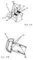
- FIGS. 2A and 2B show the effectiveness of the safety device with the plug 17 plugged into a measuring line 21.
- the cover 6 is closed.
- the plug 17 with its measuring line 21 can be removed in this state, since the locking element 15 does not protrude into the Aufsteckraum 19 due to the interaction of the first ramp 11 with the first stop 3 of the locking member 1.
- the second ramp 13 strikes with its perpendicular stop face against the likewise perpendicular end face or a corresponding stop of the blocking element 1 and prevents further opening movement of the cover 6. This results in the fact that in this state, neither a battery can be removed from the receptacle 4 nor used. This is only when the plug 17 is removed from the test socket 2.
- the locking member 1 is equipped with a plurality of locking elements 15, wherein each locking element 15 is provided for an associated measuring socket 2.
- the entire locking member 1 is mounted on both sides arranged pivot pin 18 within the housing 10 of the measuring instrument 14 pivotally.
- two are each on a receptacle 20 arranged springs 7, in particular coil springs, to ensure an energy storage and thus provided for biasing the locking member 1.
- the first stopper 3 and second stopper 5 is formed on both sides of the locking member 1 and is in accordance with Fig. 3B with correspondingly arranged and formed first and second ramps 11 and 13 in conjunction.
- the locking member 1 is suitably designed as a one-piece part, preferably as a plastic injection molded part. During assembly, the locking member 1 only needs to be inserted into the respectively provided bearing recess on the housing 10 via the pivot pin 18.
- the construction ensures on the one hand a special security in the application of measuring instruments, on the other hand, the construction can be realized with simple structural means.
- the invention therefore represents a very special contribution in the relevant field of technology.
Landscapes
- Physics & Mathematics (AREA)
- General Physics & Mathematics (AREA)
- Chemical & Material Sciences (AREA)
- Chemical Kinetics & Catalysis (AREA)
- Electrochemistry (AREA)
- General Chemical & Material Sciences (AREA)
- Details Of Connecting Devices For Male And Female Coupling (AREA)
Claims (10)
- Instrument de mesure comprenant
un boîtier (8),
au moins un compartiment de réception (4) pour un composant remplaçable, en particulier une batterie, un accumulateur et/ou une sécurité, le compartiment de réception (4) pouvant être fermé au moyen d'une partie de recouvrement (6),
au moins une douille de mesure (2) destinée à connecter l'instrument de mesure à un objet à mesurer par le biais d'une ligne de mesure (21), caractérisé en ce qu'
un organe de verrouillage mobile (1) est prévu,
la mobilité de l'organe de verrouillage (1) est déterminée de telle sorte que l'organe de verrouillage (1) libère la douille de mesure (2) dans une première position A et bloque la douille de mesure (2) dans une deuxième position B et
le mouvement de l'organe de verrouillage (1) de la première position dans la deuxième position est assuré par déplacement, en particulier coulissement, de la partie de recouvrement (6). - Instrument de mesure selon la revendication 1,
caractérisé en ce que
la deuxième position de l'organe de verrouillage (1) est précontrainte au moyen d'un accumulateur de force, en particulier d'un accumulateur à ressort. - Instrument de mesure selon la revendication 1 ou 2,
caractérisé en ce que
l'organe de verrouillage (1) présente au moins un élément de verrouillage (15) qui vient en prise dans l'espace d'enfichage (19) dans la deuxième position et qui empêche de ce fait l'enfichage d'une fiche (17) sur la douille de mesure (2). - Instrument de mesure selon la revendication 3,
caractérisé en ce que
l'organe de verrouillage (1) est réalisé sous forme de bascule, l'organe de verrouillage (1) effectuant un mouvement de pivotement pour assurer la première ou la deuxième position de l'élément de verrouillage (15),
la partie de recouvrement (6) présente une première rampe (11) qui coopère avec une première butée (3) de l'organe de verrouillage (1),
la partie de recouvrement présente une deuxième rampe (13), qui coopère avec une deuxième butée (5) de l'organe de verrouillage (1) et
la deuxième rampe (13), lorsque la fiche (17) est enfichée, empêche le mouvement de la partie de recouvrement (6). - Instrument de mesure selon la revendication 4,
caractérisé en ce que
l'organe de verrouillage (1) présente, sur chaque côté, un pivot d'articulation (18), et l'élément de verrouillage (15), considéré dans la direction longitudinale de l'organe de verrouillage (1), se situe dans la région du pivot d'articulation (18). - Instrument de mesure selon l'une quelconque des revendications 3 à 5,
caractérisé en ce que
l'organe de verrouillage (1) présente une pluralité d'éléments de verrouillage (15), chaque élément de verrouillage (15) étant associé à une douille de mesure (2). - Instrument de mesure selon l'une quelconque des revendications précédentes,
caractérisé en ce que
l'organe de verrouillage (1) est réalisé d'une seule pièce. - Instrument de mesure selon l'une quelconque des revendications précédentes,
caractérisé en ce que
la douille de mesure (2) se trouve sur le côté de l'instrument de mesure opposé à la partie de recouvrement (6). - Instrument de mesure selon l'une quelconque des revendications précédentes,
caractérisé en ce que
la partie de recouvrement (6) est déplaçable longitudinalement à la manière d'un chariot pour ouvrir ou fermer le compartiment de réception (4). - Instrument de mesure selon l'une quelconque des revendications précédentes,
caractérisé en ce
qu'au moins un, de préférence une pluralité de ressorts (7) sont prévus en tant qu'accumulateur de force, lesquels ressort sont fixés en position au moyen d'un logement (20) sur l'organe de verrouillage (1).
Applications Claiming Priority (1)
| Application Number | Priority Date | Filing Date | Title |
|---|---|---|---|
| DE202009012059U DE202009012059U1 (de) | 2009-09-07 | 2009-09-07 | Messinstrument |
Publications (2)
| Publication Number | Publication Date |
|---|---|
| EP2293085A1 EP2293085A1 (fr) | 2011-03-09 |
| EP2293085B1 true EP2293085B1 (fr) | 2014-01-01 |
Family
ID=43126922
Family Applications (1)
| Application Number | Title | Priority Date | Filing Date |
|---|---|---|---|
| EP10009267.5A Not-in-force EP2293085B1 (fr) | 2009-09-07 | 2010-09-07 | Appareil de mesure |
Country Status (2)
| Country | Link |
|---|---|
| EP (1) | EP2293085B1 (fr) |
| DE (1) | DE202009012059U1 (fr) |
Families Citing this family (1)
| Publication number | Priority date | Publication date | Assignee | Title |
|---|---|---|---|---|
| CN112290136A (zh) * | 2020-11-07 | 2021-01-29 | 湖南宝特瑞能新能源有限责任公司 | 一种锂电池安装用自锁结构的连接件 |
Family Cites Families (4)
| Publication number | Priority date | Publication date | Assignee | Title |
|---|---|---|---|---|
| FR2637153B1 (fr) * | 1988-09-27 | 1993-03-26 | Itt Composants Instr | Appareil electrique a compartiment de pile perfectionne |
| DE4438239C1 (de) * | 1994-10-26 | 1996-06-05 | Mueller & Weigert | Batteriebetriebenes Meßgerät, insbesondere Zangenanlegegerät |
| US5834935A (en) * | 1997-03-18 | 1998-11-10 | Tektronix, Inc. | Hand held instrument with safety locked battery compartment |
| DE202004017714U1 (de) * | 2004-11-15 | 2005-05-12 | Conrad Electronic Gmbh | Elektrisches Messgerät |
-
2009
- 2009-09-07 DE DE202009012059U patent/DE202009012059U1/de not_active Expired - Lifetime
-
2010
- 2010-09-07 EP EP10009267.5A patent/EP2293085B1/fr not_active Not-in-force
Also Published As
| Publication number | Publication date |
|---|---|
| EP2293085A1 (fr) | 2011-03-09 |
| DE202009012059U1 (de) | 2011-02-03 |
Similar Documents
| Publication | Publication Date | Title |
|---|---|---|
| EP2055967B1 (fr) | Bloc de batterie et appareil électrique | |
| DE102009015570B4 (de) | Halter für ein elektrisches Bauteil, sowie Verbindungsanordnung hiermit | |
| DE102012105771B4 (de) | Stecker mit Kontaktbuchse und Schutzabdeckung | |
| DE102004038123A1 (de) | Elektrischer Stecker und elektrische Steckeraufnahme | |
| DE102008014176A1 (de) | Reihenklemme, insbesondere Trennklemme | |
| DE102011076568A1 (de) | Steckverbinder | |
| DE102005001515B4 (de) | Elektrischer Steckverbinder | |
| DE102018202542A1 (de) | Klemme | |
| DE102012104538A1 (de) | Werkzeug | |
| DE102019128821A1 (de) | Klemmeneinrichtung zum Anschließen eines elektrischen Leiters | |
| DE202013009038U1 (de) | Elektrisches Steckvorrichtungssystem mit Verschlusseinrichtung | |
| EP2293085B1 (fr) | Appareil de mesure | |
| DE10347668B4 (de) | Elektrische Klemme | |
| DE202007009240U1 (de) | Kurzschlussanzeiger für elektrische Leitungen zur Energieverteilung | |
| DE102012203250B4 (de) | Einschubrahmen für ein elektrisches Einschubschaltgerät sowie Einheit aus einem Einschubrahmen und einem elektrischen Einschubschaltgerät | |
| DE202008003720U1 (de) | Schwenkhebelbetätigung mit einer Sicherheitseinrichtung | |
| DE102015013012A1 (de) | Energiezähler-Anschlussklemmenblock mit Überbrückungsvorrichtung | |
| DE10216209C1 (de) | Berührungsschutzvorrichtung mit Längsschieber für eine elektrische Steckdose | |
| DE202007007723U1 (de) | Sicherheitseinrichtung für einen Schwenkhebelstangenverschluss | |
| DE29916350U1 (de) | Sperrelement für ein Hörhilfegerät | |
| DE202010006202U1 (de) | Adapter für einen elektronischen Haushaltszähler | |
| DE102006046801A1 (de) | Elektrische Bedieneinheit für ein Fahrzeug mit einem Schacht zur Aufnahme eines Notschlüssels | |
| DE102008014180A1 (de) | Trennklemme, insbesondere Neutralleiter-Trennklemme | |
| DE202018106082U1 (de) | Anschlussleiste | |
| CH710483A2 (de) | Steckdosenadapter. |
Legal Events
| Date | Code | Title | Description |
|---|---|---|---|
| PUAI | Public reference made under article 153(3) epc to a published international application that has entered the european phase |
Free format text: ORIGINAL CODE: 0009012 |
|
| AK | Designated contracting states |
Kind code of ref document: A1 Designated state(s): AL AT BE BG CH CY CZ DE DK EE ES FI FR GB GR HR HU IE IS IT LI LT LU LV MC MK MT NL NO PL PT RO SE SI SK SM TR |
|
| AX | Request for extension of the european patent |
Extension state: BA ME RS |
|
| 17P | Request for examination filed |
Effective date: 20110817 |
|
| RIC1 | Information provided on ipc code assigned before grant |
Ipc: H05K 5/02 20060101ALI20130419BHEP Ipc: G01D 11/24 20060101ALI20130419BHEP Ipc: G01R 19/25 20060101ALI20130419BHEP Ipc: G01R 1/04 20060101AFI20130419BHEP Ipc: H01M 2/10 20060101ALI20130419BHEP Ipc: G01R 15/12 20060101ALI20130419BHEP Ipc: H05K 5/00 20060101ALI20130419BHEP |
|
| GRAP | Despatch of communication of intention to grant a patent |
Free format text: ORIGINAL CODE: EPIDOSNIGR1 |
|
| INTG | Intention to grant announced |
Effective date: 20130730 |
|
| GRAS | Grant fee paid |
Free format text: ORIGINAL CODE: EPIDOSNIGR3 |
|
| GRAA | (expected) grant |
Free format text: ORIGINAL CODE: 0009210 |
|
| AK | Designated contracting states |
Kind code of ref document: B1 Designated state(s): AL AT BE BG CH CY CZ DE DK EE ES FI FR GB GR HR HU IE IS IT LI LT LU LV MC MK MT NL NO PL PT RO SE SI SK SM TR |
|
| REG | Reference to a national code |
Ref country code: GB Ref legal event code: FG4D Free format text: NOT ENGLISH |
|
| REG | Reference to a national code |
Ref country code: CH Ref legal event code: EP |
|
| REG | Reference to a national code |
Ref country code: IE Ref legal event code: FG4D Free format text: LANGUAGE OF EP DOCUMENT: GERMAN |
|
| REG | Reference to a national code |
Ref country code: DE Ref legal event code: R096 Ref document number: 502010005804 Country of ref document: DE Effective date: 20140213 |
|
| REG | Reference to a national code |
Ref country code: AT Ref legal event code: REF Ref document number: 647813 Country of ref document: AT Kind code of ref document: T Effective date: 20140215 |
|
| REG | Reference to a national code |
Ref country code: CH Ref legal event code: NV Representative=s name: PATENTANWAELTE SCHAAD, BALASS, MENZL AND PARTN, CH |
|
| REG | Reference to a national code |
Ref country code: NL Ref legal event code: T3 |
|
| REG | Reference to a national code |
Ref country code: LT Ref legal event code: MG4D |
|
| PG25 | Lapsed in a contracting state [announced via postgrant information from national office to epo] |
Ref country code: IS Free format text: LAPSE BECAUSE OF FAILURE TO SUBMIT A TRANSLATION OF THE DESCRIPTION OR TO PAY THE FEE WITHIN THE PRESCRIBED TIME-LIMIT Effective date: 20140501 Ref country code: LT Free format text: LAPSE BECAUSE OF FAILURE TO SUBMIT A TRANSLATION OF THE DESCRIPTION OR TO PAY THE FEE WITHIN THE PRESCRIBED TIME-LIMIT Effective date: 20140101 |
|
| PG25 | Lapsed in a contracting state [announced via postgrant information from national office to epo] |
Ref country code: FI Free format text: LAPSE BECAUSE OF FAILURE TO SUBMIT A TRANSLATION OF THE DESCRIPTION OR TO PAY THE FEE WITHIN THE PRESCRIBED TIME-LIMIT Effective date: 20140101 Ref country code: ES Free format text: LAPSE BECAUSE OF FAILURE TO SUBMIT A TRANSLATION OF THE DESCRIPTION OR TO PAY THE FEE WITHIN THE PRESCRIBED TIME-LIMIT Effective date: 20140101 Ref country code: SE Free format text: LAPSE BECAUSE OF FAILURE TO SUBMIT A TRANSLATION OF THE DESCRIPTION OR TO PAY THE FEE WITHIN THE PRESCRIBED TIME-LIMIT Effective date: 20140101 Ref country code: CY Free format text: LAPSE BECAUSE OF FAILURE TO SUBMIT A TRANSLATION OF THE DESCRIPTION OR TO PAY THE FEE WITHIN THE PRESCRIBED TIME-LIMIT Effective date: 20140101 Ref country code: PT Free format text: LAPSE BECAUSE OF FAILURE TO SUBMIT A TRANSLATION OF THE DESCRIPTION OR TO PAY THE FEE WITHIN THE PRESCRIBED TIME-LIMIT Effective date: 20140502 |
|
| PG25 | Lapsed in a contracting state [announced via postgrant information from national office to epo] |
Ref country code: LV Free format text: LAPSE BECAUSE OF FAILURE TO SUBMIT A TRANSLATION OF THE DESCRIPTION OR TO PAY THE FEE WITHIN THE PRESCRIBED TIME-LIMIT Effective date: 20140101 Ref country code: HR Free format text: LAPSE BECAUSE OF FAILURE TO SUBMIT A TRANSLATION OF THE DESCRIPTION OR TO PAY THE FEE WITHIN THE PRESCRIBED TIME-LIMIT Effective date: 20140101 |
|
| REG | Reference to a national code |
Ref country code: DE Ref legal event code: R097 Ref document number: 502010005804 Country of ref document: DE |
|
| PG25 | Lapsed in a contracting state [announced via postgrant information from national office to epo] |
Ref country code: RO Free format text: LAPSE BECAUSE OF FAILURE TO SUBMIT A TRANSLATION OF THE DESCRIPTION OR TO PAY THE FEE WITHIN THE PRESCRIBED TIME-LIMIT Effective date: 20140101 Ref country code: DK Free format text: LAPSE BECAUSE OF FAILURE TO SUBMIT A TRANSLATION OF THE DESCRIPTION OR TO PAY THE FEE WITHIN THE PRESCRIBED TIME-LIMIT Effective date: 20140101 Ref country code: CZ Free format text: LAPSE BECAUSE OF FAILURE TO SUBMIT A TRANSLATION OF THE DESCRIPTION OR TO PAY THE FEE WITHIN THE PRESCRIBED TIME-LIMIT Effective date: 20140101 Ref country code: EE Free format text: LAPSE BECAUSE OF FAILURE TO SUBMIT A TRANSLATION OF THE DESCRIPTION OR TO PAY THE FEE WITHIN THE PRESCRIBED TIME-LIMIT Effective date: 20140101 |
|
| PLBE | No opposition filed within time limit |
Free format text: ORIGINAL CODE: 0009261 |
|
| STAA | Information on the status of an ep patent application or granted ep patent |
Free format text: STATUS: NO OPPOSITION FILED WITHIN TIME LIMIT |
|
| PG25 | Lapsed in a contracting state [announced via postgrant information from national office to epo] |
Ref country code: SK Free format text: LAPSE BECAUSE OF FAILURE TO SUBMIT A TRANSLATION OF THE DESCRIPTION OR TO PAY THE FEE WITHIN THE PRESCRIBED TIME-LIMIT Effective date: 20140101 Ref country code: PL Free format text: LAPSE BECAUSE OF FAILURE TO SUBMIT A TRANSLATION OF THE DESCRIPTION OR TO PAY THE FEE WITHIN THE PRESCRIBED TIME-LIMIT Effective date: 20140101 |
|
| 26N | No opposition filed |
Effective date: 20141002 |
|
| REG | Reference to a national code |
Ref country code: DE Ref legal event code: R097 Ref document number: 502010005804 Country of ref document: DE Effective date: 20141002 |
|
| PG25 | Lapsed in a contracting state [announced via postgrant information from national office to epo] |
Ref country code: LU Free format text: LAPSE BECAUSE OF FAILURE TO SUBMIT A TRANSLATION OF THE DESCRIPTION OR TO PAY THE FEE WITHIN THE PRESCRIBED TIME-LIMIT Effective date: 20140907 Ref country code: MC Free format text: LAPSE BECAUSE OF FAILURE TO SUBMIT A TRANSLATION OF THE DESCRIPTION OR TO PAY THE FEE WITHIN THE PRESCRIBED TIME-LIMIT Effective date: 20140101 |
|
| GBPC | Gb: european patent ceased through non-payment of renewal fee |
Effective date: 20140907 |
|
| PG25 | Lapsed in a contracting state [announced via postgrant information from national office to epo] |
Ref country code: SI Free format text: LAPSE BECAUSE OF FAILURE TO SUBMIT A TRANSLATION OF THE DESCRIPTION OR TO PAY THE FEE WITHIN THE PRESCRIBED TIME-LIMIT Effective date: 20140101 |
|
| REG | Reference to a national code |
Ref country code: IE Ref legal event code: MM4A |
|
| PG25 | Lapsed in a contracting state [announced via postgrant information from national office to epo] |
Ref country code: BE Free format text: LAPSE BECAUSE OF NON-PAYMENT OF DUE FEES Effective date: 20140930 |
|
| PG25 | Lapsed in a contracting state [announced via postgrant information from national office to epo] |
Ref country code: GB Free format text: LAPSE BECAUSE OF NON-PAYMENT OF DUE FEES Effective date: 20140907 |
|
| PG25 | Lapsed in a contracting state [announced via postgrant information from national office to epo] |
Ref country code: IE Free format text: LAPSE BECAUSE OF NON-PAYMENT OF DUE FEES Effective date: 20140907 |
|
| REG | Reference to a national code |
Ref country code: FR Ref legal event code: PLFP Year of fee payment: 6 |
|
| PGFP | Annual fee paid to national office [announced via postgrant information from national office to epo] |
Ref country code: CH Payment date: 20150922 Year of fee payment: 6 Ref country code: DE Payment date: 20150903 Year of fee payment: 6 |
|
| PGFP | Annual fee paid to national office [announced via postgrant information from national office to epo] |
Ref country code: AT Payment date: 20150921 Year of fee payment: 6 Ref country code: FR Payment date: 20150923 Year of fee payment: 6 |
|
| PGFP | Annual fee paid to national office [announced via postgrant information from national office to epo] |
Ref country code: NL Payment date: 20150923 Year of fee payment: 6 |
|
| PG25 | Lapsed in a contracting state [announced via postgrant information from national office to epo] |
Ref country code: NO Free format text: LAPSE BECAUSE OF FAILURE TO SUBMIT A TRANSLATION OF THE DESCRIPTION OR TO PAY THE FEE WITHIN THE PRESCRIBED TIME-LIMIT Effective date: 20140401 Ref country code: SM Free format text: LAPSE BECAUSE OF FAILURE TO SUBMIT A TRANSLATION OF THE DESCRIPTION OR TO PAY THE FEE WITHIN THE PRESCRIBED TIME-LIMIT Effective date: 20140101 |
|
| PG25 | Lapsed in a contracting state [announced via postgrant information from national office to epo] |
Ref country code: IT Free format text: LAPSE BECAUSE OF FAILURE TO SUBMIT A TRANSLATION OF THE DESCRIPTION OR TO PAY THE FEE WITHIN THE PRESCRIBED TIME-LIMIT Effective date: 20140101 Ref country code: MT Free format text: LAPSE BECAUSE OF FAILURE TO SUBMIT A TRANSLATION OF THE DESCRIPTION OR TO PAY THE FEE WITHIN THE PRESCRIBED TIME-LIMIT Effective date: 20140101 Ref country code: BG Free format text: LAPSE BECAUSE OF FAILURE TO SUBMIT A TRANSLATION OF THE DESCRIPTION OR TO PAY THE FEE WITHIN THE PRESCRIBED TIME-LIMIT Effective date: 20140101 Ref country code: GR Free format text: LAPSE BECAUSE OF FAILURE TO SUBMIT A TRANSLATION OF THE DESCRIPTION OR TO PAY THE FEE WITHIN THE PRESCRIBED TIME-LIMIT Effective date: 20140402 |
|
| PG25 | Lapsed in a contracting state [announced via postgrant information from national office to epo] |
Ref country code: TR Free format text: LAPSE BECAUSE OF FAILURE TO SUBMIT A TRANSLATION OF THE DESCRIPTION OR TO PAY THE FEE WITHIN THE PRESCRIBED TIME-LIMIT Effective date: 20140101 Ref country code: HU Free format text: LAPSE BECAUSE OF FAILURE TO SUBMIT A TRANSLATION OF THE DESCRIPTION OR TO PAY THE FEE WITHIN THE PRESCRIBED TIME-LIMIT; INVALID AB INITIO Effective date: 20100907 |
|
| REG | Reference to a national code |
Ref country code: DE Ref legal event code: R119 Ref document number: 502010005804 Country of ref document: DE |
|
| REG | Reference to a national code |
Ref country code: CH Ref legal event code: PL |
|
| REG | Reference to a national code |
Ref country code: NL Ref legal event code: MM Effective date: 20161001 |
|
| REG | Reference to a national code |
Ref country code: AT Ref legal event code: MM01 Ref document number: 647813 Country of ref document: AT Kind code of ref document: T Effective date: 20160907 |
|
| PG25 | Lapsed in a contracting state [announced via postgrant information from national office to epo] |
Ref country code: NL Free format text: LAPSE BECAUSE OF NON-PAYMENT OF DUE FEES Effective date: 20161001 |
|
| REG | Reference to a national code |
Ref country code: FR Ref legal event code: ST Effective date: 20170531 |
|
| PG25 | Lapsed in a contracting state [announced via postgrant information from national office to epo] |
Ref country code: CH Free format text: LAPSE BECAUSE OF NON-PAYMENT OF DUE FEES Effective date: 20160930 Ref country code: DE Free format text: LAPSE BECAUSE OF NON-PAYMENT OF DUE FEES Effective date: 20170401 Ref country code: LI Free format text: LAPSE BECAUSE OF NON-PAYMENT OF DUE FEES Effective date: 20160930 Ref country code: FR Free format text: LAPSE BECAUSE OF NON-PAYMENT OF DUE FEES Effective date: 20160930 |
|
| PG25 | Lapsed in a contracting state [announced via postgrant information from national office to epo] |
Ref country code: AT Free format text: LAPSE BECAUSE OF NON-PAYMENT OF DUE FEES Effective date: 20160907 |
|
| PG25 | Lapsed in a contracting state [announced via postgrant information from national office to epo] |
Ref country code: MK Free format text: LAPSE BECAUSE OF FAILURE TO SUBMIT A TRANSLATION OF THE DESCRIPTION OR TO PAY THE FEE WITHIN THE PRESCRIBED TIME-LIMIT Effective date: 20140101 |
|
| PG25 | Lapsed in a contracting state [announced via postgrant information from national office to epo] |
Ref country code: AL Free format text: LAPSE BECAUSE OF FAILURE TO SUBMIT A TRANSLATION OF THE DESCRIPTION OR TO PAY THE FEE WITHIN THE PRESCRIBED TIME-LIMIT Effective date: 20140101 |