EP2293104A2 - Système et procédé pour la correction de la mesure de phases de porteuse d'un système de navigation par satellites globale dont des récepteurs sont dotés d'antennes de diagrammes contrôlés - Google Patents
Système et procédé pour la correction de la mesure de phases de porteuse d'un système de navigation par satellites globale dont des récepteurs sont dotés d'antennes de diagrammes contrôlés Download PDFInfo
- Publication number
- EP2293104A2 EP2293104A2 EP10251318A EP10251318A EP2293104A2 EP 2293104 A2 EP2293104 A2 EP 2293104A2 EP 10251318 A EP10251318 A EP 10251318A EP 10251318 A EP10251318 A EP 10251318A EP 2293104 A2 EP2293104 A2 EP 2293104A2
- Authority
- EP
- European Patent Office
- Prior art keywords
- transmitter
- crpa
- gnss
- beam steering
- steering control
- Prior art date
- Legal status (The legal status is an assumption and is not a legal conclusion. Google has not performed a legal analysis and makes no representation as to the accuracy of the status listed.)
- Withdrawn
Links
- 238000005259 measurement Methods 0.000 title claims abstract description 36
- 238000000034 method Methods 0.000 title claims abstract description 35
- 238000012937 correction Methods 0.000 claims abstract description 49
- 239000002131 composite material Substances 0.000 claims description 12
- 238000005070 sampling Methods 0.000 claims description 2
- 230000003068 static effect Effects 0.000 claims description 2
- 230000001419 dependent effect Effects 0.000 abstract description 11
- 230000002708 enhancing effect Effects 0.000 abstract 1
- 239000013598 vector Substances 0.000 description 16
- 230000000694 effects Effects 0.000 description 15
- 230000001934 delay Effects 0.000 description 11
- 230000010363 phase shift Effects 0.000 description 7
- 230000008569 process Effects 0.000 description 7
- 230000005540 biological transmission Effects 0.000 description 6
- 238000012545 processing Methods 0.000 description 6
- 230000001151 other effect Effects 0.000 description 4
- 230000003044 adaptive effect Effects 0.000 description 2
- 238000013459 approach Methods 0.000 description 2
- 230000008901 benefit Effects 0.000 description 2
- 238000013461 design Methods 0.000 description 2
- 230000036541 health Effects 0.000 description 2
- 230000033001 locomotion Effects 0.000 description 2
- 238000012986 modification Methods 0.000 description 2
- 230000004048 modification Effects 0.000 description 2
- 230000018199 S phase Effects 0.000 description 1
- 230000006978 adaptation Effects 0.000 description 1
- 238000003491 array Methods 0.000 description 1
- 238000006243 chemical reaction Methods 0.000 description 1
- 230000001427 coherent effect Effects 0.000 description 1
- 230000003111 delayed effect Effects 0.000 description 1
- 238000011161 development Methods 0.000 description 1
- 238000013101 initial test Methods 0.000 description 1
- 230000003993 interaction Effects 0.000 description 1
- 230000000116 mitigating effect Effects 0.000 description 1
- 238000011160 research Methods 0.000 description 1
- 238000010561 standard procedure Methods 0.000 description 1
- 230000001360 synchronised effect Effects 0.000 description 1
Images


Classifications
-
- G—PHYSICS
- G01—MEASURING; TESTING
- G01S—RADIO DIRECTION-FINDING; RADIO NAVIGATION; DETERMINING DISTANCE OR VELOCITY BY USE OF RADIO WAVES; LOCATING OR PRESENCE-DETECTING BY USE OF THE REFLECTION OR RERADIATION OF RADIO WAVES; ANALOGOUS ARRANGEMENTS USING OTHER WAVES
- G01S19/00—Satellite radio beacon positioning systems; Determining position, velocity or attitude using signals transmitted by such systems
- G01S19/01—Satellite radio beacon positioning systems transmitting time-stamped messages, e.g. GPS [Global Positioning System], GLONASS [Global Orbiting Navigation Satellite System] or GALILEO
- G01S19/13—Receivers
- G01S19/23—Testing, monitoring, correcting or calibrating of receiver elements
-
- G—PHYSICS
- G01—MEASURING; TESTING
- G01S—RADIO DIRECTION-FINDING; RADIO NAVIGATION; DETERMINING DISTANCE OR VELOCITY BY USE OF RADIO WAVES; LOCATING OR PRESENCE-DETECTING BY USE OF THE REFLECTION OR RERADIATION OF RADIO WAVES; ANALOGOUS ARRANGEMENTS USING OTHER WAVES
- G01S19/00—Satellite radio beacon positioning systems; Determining position, velocity or attitude using signals transmitted by such systems
- G01S19/01—Satellite radio beacon positioning systems transmitting time-stamped messages, e.g. GPS [Global Positioning System], GLONASS [Global Orbiting Navigation Satellite System] or GALILEO
- G01S19/13—Receivers
- G01S19/24—Acquisition or tracking or demodulation of signals transmitted by the system
- G01S19/29—Acquisition or tracking or demodulation of signals transmitted by the system carrier including Doppler, related
Definitions
- the present invention relates to the field of Global Navigation Satellite Systems (GNSS), such as the Global Positioning System (GPS), and, more particularly, to carrier phase measurements in such systems.
- GNSS Global Navigation Satellite Systems
- GPS Global Positioning System
- GNSS Global Navigation Satellite Systems
- the modulation used by these signals and the data messages included enable the receivers to determine highly accurate navigational locations anywhere on the Earth.
- the receiver calculates its position by carefully measuring the time of arrival of the signals sent by several of the satellites.
- Each satellite continually transmits messages containing the time the message was sent, precise orbital information, and the general system health and approximate orbits of all the satellites.
- a time of propagation can be determined and transformed into a range using the speed of propagation "c”.
- GNSS is considered a dual-use technology, namely, a technology that has significant civilian and military applications. Accordingly, for an example GNSS like the Global Positioning System (GPS), the satellites broadcast on precisely defined carrier frequencies with well-defined modulation.
- GPS Global Positioning System
- the GPS data and timing signals intended for everyone's use have a publicly-defined format contained in Interface Specification IS-GPS-200, available at http://www.navcen.uscg.gov/gps/geninfo/IS-GPS-200D.pdf, and are unencrypted, while those timing signals intended for military use are not publicly defined and are encrypted and the military specific information content is also encrypted.
- the satellite employs a pseudorandom code, which is used to modulate the carrier frequency in order to transmit the precise time marks.
- the carrier frequencies are over 1 GHz, while the code rates are considerably lower.
- GPS chip rates are roughly 10 MHz for the military code and 1 MHz for the civilian code. Additionally, data messages containing satellite orbit, system health, and other necessary information, are transmitted at even a lower rate of 50 bits per second.
- FRPA fixed reception pattern antenna
- CRPA multiple element controlled reception pattern antenna
- the receiver measures the transit time, using the precise time marks provided by the pseudorandom code, from a satellite and computes the distance to that satellite by multiplying the transit time by the speed of light.
- These distance computations are called “pseudoranges” since there is almost always a time difference between the atomic satellite clocks used to create the precise time marks and the receiver clocks used to decode the precise time marks.
- This clock error is common to all measurements since the atomic satellite clocks are all synchronized, and results in a common range error.
- This common range error is what forms a "pseudorange" from an absolute range.
- Other effects that give rise to range errors include atmospheric and receiver antenna hardware.
- Geometric multilateration is used to pinpoint the receiver's location by combining these pseudoranges with the corresponding locations of the satellites, using the data from at least four different satellites.
- Four pseudoranges also allow determination of the clock bias associated with the common range error described above, which adds a fourth dimension of uncertainty, when trying to solve for the other three dimensions of a physical location. Nonetheless, other effects that contribute to range measurement errors still remain. Identifying and attempting to account for the multiple sources of errors is an important step to improving the accuracy of locations determined through GNSS.
- Atmospheric i.e., ionospheric and tropospheric
- the Earth's atmosphere slows down the speed of the satellite transmissions.
- These errors can be compensated for in a number of ways. For instance, using satellites that are more directly overhead helps because their transmissions travel through less atmosphere than when using satellites closer to the horizon.
- having the satellites transmit on multiple frequencies helps mitigate the ionospheric induced errors since it is frequency-dependent, so can be mitigated by combining the measurements from the two frequencies into a single ionospheric free measurement.
- relative posititioning systems such as Differential GPS, use strategically placed monitor stations at exact locations to determine at any given time what the overall transmission delay (including effects like atmospheric) is for each satellite. These monitor stations then broadcast these delays to all nearby receivers, which then can make the corrections to each of the corresponding satellites.
- the satellite signals are relatively weak, it is fairly straightforward to intentionally jam such signals, either by increasing the noise floor by transmitting a broadband noise jammer or by attempting to exceed the dynamic range of the receiver hardware with powerful narrowband signals. Additionally, since the satellite signal structure is so precisely defined and predictable, it can be spoofed by a transmission using the same frequencies and signal structure. This is unacceptable for military applications, so they rely on encrypted signals to thwart any spoofed transmissions, but are still susceptible to intentional interference on the same frequencies. Consequently, for military applications, there is a need to reduce the effect of jamming, so the CRPA system is sometimes used in place of the FRPA system.
- CRPA systems can use techniques such as nulling (combining the signals received by the CRPA's elements in such a way as to make the jamming signal cancel itself out) or beam steering (combining the signals received by the CRPA's elements in such a way as to amplify the satellite signal) to overcome intentional jamming.
- nulling combining the signals received by the CRPA's elements in such a way as to make the jamming signal cancel itself out
- beam steering combining the signals received by the CRPA's elements in such a way as to amplify the satellite signal
- GPS L1 has a wavelength of 19.0 cm
- GPS L2 has a wavelength of 24.4 cm.
- Sophisticated equipment can resolve down to a fraction of these wavelengths, producing extremely precise and accurate range measurements.
- the problem is that the phase center of reception of such waves can be difficult to determine for multiple element antennas tracking satellites from different angles. Without compensation, this effect contributes error when performing GNSS carrier phase measurements.
- GNSS carrier phase measurements should be compensated for receiver hardware and directionally dependent antenna errors to obtain desired accuracies for high precision GNSS positioning applications.
- High accuracy carrier phase correction techniques implemented in the measurement domain have existed for a number of years. See, for example, Gerald L. Mader, GPS Antenna Calibration at the National Geodetic Survey, available at http://www.ngs.noaa.gov/ANTCAL/images/summary.html , the entire content of which is herein incorporated by reference. These techniques are usually based upon the GPS antenna phase-correction methodology pioneered by National Geodetic Survey (NGS), and are primarily applicable to GPS receivers that employ FRPAs. See the NGS home page at http://www.ngs.noaa.gov/ANTCAL/ for further FRPA error correction technical background.
- NGS National Geodetic Survey
- Embodiments of the present invention provide a system and method for correcting errors in GNSS carrier phase measurements that use CRPA receiver systems.
- the method is implemented as a correction to the beam steering vectors, such that the correction to the carrier phase for each of the beams is inherently a part of the beam forming process when beam steering is active.
- One advantage of this approach is that the carrier phase measurements are fully compensated (for the primary beam satellite for each beam) prior to the input of the signals to the GNSS processing device for processing in the GNSS tracking loop software.
- Exemplary embodiments of the present invention provide for operating configurations for CRPA signal processing modes, including beam steering, and adaptive nulling with beam steering.
- an apparatus for calibrating a global navigation satellite system (GNSS) receiver for errors in carrier phase measurements of GNSS transmitter signals includes: a controlled reception pattern antenna (CRPA) including a plurality of receiving elements and configured to sense a plurality of signals from a GNSS transmitter; a digital sampler circuit configured to convert the plurality of sensed GNSS signals to a plurality of sampled digital signals; and a digital processor.
- a controlled reception pattern antenna CRPA
- the digital processor is configured to: access phase calibration correction data for at least some combinations of the plurality of receiving elements and a plurality of transmitter orientations with respect to the CRPA; generate beam steering control data using a transmitter orientation with respect to the CRPA; combine the phase calibration correction data specific to the transmitter orientation with respect to the CRPA and each of the plurality of receiving elements together with the beam steering control data to generate corrected beam steering control data; generate a composite corrected digital signal by combining the sampled digital signals and the corrected beam steering control data; and convert the composite corrected digital signal into a corrected GNSS carrier phase measurement.
- the CRPA may be further configured to sense the plurality of signals from a plurality of GNSS transmitters using one or more transmitter frequencies.
- the digital processor may be further configured to: access phase calibration correction data for at least some combinations of the plurality of receiving elements, the plurality of transmitter orientations with respect to the CRPA, and the one or more transmitter frequencies; generate a plurality of beam steering control data at each of the one or more transmitter frequencies for the respective plurality of GNSS transmitters using respective transmitter orientations with respect to the CRPA; combine the phase calibration correction data specific to the transmitter orientations with respect to the CRPA, the transmitter frequency, and each of the plurality of receiving elements together with the plurality of beam steering control data at each of the one or more transmitter frequencies to generate a plurality of corrected beam steering control data at each of the one or more transmitter frequencies; and generate a composite corrected digital signal for each of the plurality of GNSS transmitters at each of the one or more transmitter frequencies by combining the sampled digital signals and the plurality of corrected beam steering control data at each of the one
- the apparatus may further include an orientation processor configured to determine the orientation of the transmitter with respect to the CRPA for each of the plurality of GNSS transmitters.
- a method for calibrating a global navigation satellite system (GNSS) receiver for errors in carrier phase measurements of GNSS transmitter signals includes: sensing a plurality of signals from a GNSS transmitter with a controlled reception pattern antenna (CRPA) including a plurality of receiving elements; digitally sampling the sensed GNSS signals to produce a plurality of sampled digital signals; accessing phase calibration correction data for at least some combinations of the plurality of receiving elements and a plurality of transmitter orientations with respect to the CRPA; generating beam steering control data using a transmitter orientation with respect to the CRPA; combining the phase calibration correction data specific to the transmitter orientation with respect to the CRPA and each of the plurality of receiving elements together with the beam steering control data to generate corrected beam steering control data; generating a composite corrected digital signal by combining the sampled digital signals and the corrected beam steering control data; converting the composite corrected digital signal into a corrected GNSS carrier phase measurement.
- CRPA controlled reception pattern antenna
- the CRPA may be further configured to sense the plurality of signals from a plurality of GNSS transmitters using one or more transmitter frequencies.
- the method may further include: determining the transmitter orientation with respect to the CRPA for each of the plurality of GNSS transmitters; accessing phase calibration correction data for at least some combinations of the plurality of receiving elements, the plurality of transmitter orientations with respect to the CRPA, and the one or more transmitter frequencies; generating a plurality of beam steering control data at each of the one or more transmitter frequencies for the respective plurality of GNSS transmitters using the respective transmitter orientations with respect to the CRPA; combining the phase calibration correction data specific to the transmitter orientations with respect to the CRPA, the transmitter frequency, and each of the plurality of receiving elements together with the plurality of beam steering control data at each of the one or more transmitter frequencies to generate a plurality of corrected beam steering control data at each of the one or more transmitter frequencies; and generating a composite corrected digital signal for each of the plurality of GNSS transmitters at each of the one
- FIG. 1 shows an exemplary CRPA 20 comprising seven antenna elements (channels).
- the seven elements are comprised of one reference element 22 and six auxiliary elements 24, where the reference element 22 is the principal element centered with respect to the seven elements while the six auxiliary elements 24 surround the reference element 22 in a symmetrical layout: one forward, one back, two on the left, and two on the right.
- a CRPA may consist of other numbers of elements, and the elements may differ in relative orientation, which may be either symmetric or asymmetric.
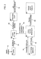
- CRPA 20 receives a signal 10 from one or more radio navigation transmitters, such as GNSS satellites.
- the CRPA 20 consists of M antenna elements ( M ⁇ 2). Each element receives a signal (Signal 1 through Signal M, for a total of M signals 25) from each transmitter.
- the receiver digitally samples the M signals 25 and sends them to CRPA filter 30. If the receiver is installed on a dynamic platform, an attitude sensor 40, such as an inertial navigation system, computes the vehicle's (and thereby the CRPA's) attitude 45. If the receiver is static, fixed values of attitude 45 may instead be supplied.
- CRPA filter manager 50 uses the attitude 45 to transform each transmitter line-of-sight (LOS) vector 15 from navigation coordinates to antenna coordinates. It then computes each of the transmitter's azimuth and elevation angles from the transformed LOS vector and uses those angles to look up the phase corrections 65 in phase shift tables 60, one table for each antenna element.
- the phase shift tables 60 contain values measured during antenna calibration, indexed by azimuth and elevation.
- the CRPA filter 30 computes weights from the corrected steering vector 55 (and in some cases from the signals 25 as well) and uses the weights to compute a filtered signal 35 from the N input signals 25.
- the receiver sends the filtered signal 35 to a tracking loop 70, which tracks the signal's carrier and forms a carrier phase (CP) measurement 75.
- CP carrier phase
- the CRPA filter manager 50 computes each of the N steering vectors 55 that are used by the CRPA filter 30.
- the role of the steering vector is to (1) increase the antenna's gain toward the selected transmitter and (2) preserve the phase of the transmitter's signal.
- the phase of a channel's output is determined by the corresponding antenna element's location, its phase shift, and the phase shifts of any cables and analog filters that are part of the channel.
- LOS is the line-of-sight unit vector from the receiver to the satellite in antenna coordinates.
- ⁇ A mf is the vector from the m th CRPA element's mechanical center to its electrical phase center using frequency
- the electrical phase center is the antenna element's mean effective reference point, averaged over all possible signal angles of arrival.
- the f subscript is needed because the element's phase center location may be different at different signal frequencies.
- ⁇ f is the signal's wavelength.
- ⁇ mf (AZ,EL) is the m th element's directionally dependent phase shift at frequency ffor signals arriving from azimuth AZ and elevation EL.
- ⁇ mf is commonly known as "phase center variation.”
- ⁇ mf is the phase shift contributed by the internal cables and analog filters.
- ⁇ mf is the phase shift contributed by the external cables and antenna elements, and includes the "phase wind-up" bias caused by the azimuth of the m th element within the CRPA array, if the antennas are circularly polarized, such as those often used by GPS receivers.
- the A m term in the formula is used by any CRPA that steers a beam toward a transmitter.
- the ⁇ A , ⁇ , ⁇ , and ⁇ terms are used to form the phase correction. These terms are obtained by calibrating the antenna elements and the CRPA channels.
- Each of the M antenna elements is calibrated separately, using a variant of the standard technique described by Mader for calibrating a FRPA. This technique, which involves holding the antenna fixed at a known position and recording carrier phase measurements (at all relevant frequencies) as the satellites move along their orbits, determines ⁇ A and ⁇ .
- the CRPA channels may be calibrated by a number of known techniques, including, for example, feeding identical carrier wave signals into all channels and measuring the phase differences at their outputs.
- ⁇ A , ⁇ , ⁇ , and ⁇ are stored in look-up tables, each with its own indexing scheme. Note that other storage schemes are possible.
- the ⁇ A table is N f ⁇ M ⁇ 3, where N f is the number of distinct carrier frequencies (2 for military GPS) and M is the number of antenna elements.
- the three table entries hold the x, y, and z components of the ⁇ A vector.
- the ⁇ table is N f ⁇ M ⁇ N a ⁇ N e , where N a and N e are the numbers of azimuth and elevation bins into which the antenna's field of view is divided.
- the ⁇ and ⁇ tables are each N f ⁇ M .
- FIG. 3 shows an example method of correcting CRPA GNSS carrier phase errors according to the present invention, where the CRPA is mounted in a vehicle. It starts with sensing GNSS transmitter signals in step 80 using a CRPA, each element sensing its own GNSS signals. Next, the signals are digitally sampled in step 82 so that mathematical operations can be performed on them. In step 84, the line-of-sight (LOS) is determined from the CRPA to the transmitter (satellite), using such variables as the current location of the transmitter with respect to the vehicle and the orientation of the CRPA within the vehicle.
- LOS line-of-sight
- phase corrections are looked up in step 86, using tables of values measured during antenna calibration, and combined with the transmitter-CRPA orientation information to produce steering vectors to combine the separate GNSS signals into one signal.
- This combining takes place in step 88, resulting in a filtered signal that combines and corrects all of the individual element signals so that they preserve the transmitter's signal phase.
- this filtered signal is sent to a tracking loop, which is able to track the signal's carrier and form a carrier phase measurement.
- the CRPA is as in FIG. 1 , that the CRPA is mounted in an aircraft, and that there are two separate frequencies employed in the GNSS.
- the first effect is the inter-channel phase delays, both internal and external.
- This set of phase correction factors is intended to provide carrier phase corrections to compensate for inter-channel phase delays between the reference channel and the six auxiliary channels. These phase delays would be expected to result primarily from differential phase delays in analog electrical components in the internal RF circuitry and by the external cables and antenna elements.
- ⁇ mf there are 14 different factors in the internal correction term ⁇ mf , one factor for each combination of frequency (two) and antenna element (seven). While it could be implemented using only 12 factors (the reference element factors could be implicitly zero, since these delays are relative to the reference element), using 14 factors provides more symmetry. It also allows these factors to incorporate an offset common to all the antenna elements. Similarly, there are 14 different factors in the external correction term ⁇ mf , one factor for each combination of frequency (two) and antenna element (seven).
- correction factors can be determined during initial testing, under conditions where all other effects that would create a difference between antenna elements are either eliminated or more completely understood.
- the next effect is the location of the different CRPA phase centers. It is from the phase center that an antenna element observes a carrier wave, so both the antenna's location and the carrier frequency play a role in this effect.
- This set of mean phase center coordinate offsets is intended to provide coordinate offsets to account for the differential coordinate positions between the mechanical reference point and the electrical reference point of each of the seven CRPA elements. It results primarily from mean differential phase delays in the antenna elements that vary with the two frequencies, and the element physical location on the antenna. That is, the factors account for the effects of antenna location and carrier frequency on the location of the corresponding phase center.
- phase centers are analogous to the single element antennas, as discussed in the Mader reference above, only for each of the seven elements in the CRPA.
- the process is sometimes referred to as “finding the mean phase center offset" of the antenna, or “calibrating the mean electrical phase center” of the antenna.
- the third effect is that of the location of satellite in the sky on the different CRPA phase centers. This can necessitate a correction in the carrier wave phase that is also dependent on antenna element and frequency, along with azimuth (horizontal) and elevation (vertical) angles to the satellite with respect to the horizon. While antenna and frequency create the 14 combinations discussed in the above effects, azimuth and elevation can create a potentially infinite number of combinations.
- One practical way to limit this in this embodiment is to consider only azimuths and elevations in ranges of n degrees, thus producing 360/ n azimuth bins and 90/ n elevation bins, where n is the azimuth/elevation bin size in degrees, and, for example, may be a number between 1 and 5 degrees. This limits the total number of combinations (factors) to 14 ⁇ 360 / n ⁇ 90 / n .
- n does not have to be the same for azimuth and elevation.
- most ground based FRPA systems exhibit little bias in azimuth, so even one bin may suffice for azimuth.
- the classic approach in the high precision phase community used for many years has been to primarily use 5-degree elevation bins (e.g., the National Geodetic Survey (NGS) phase correction models discussed in Mader above) with no azimuth dependency.
- NGS National Geodetic Survey
- These classic applications employ FRPA antennas that in the vast majority of cases are symmetric in azimuth. Because some less predictable interactions between antenna elements in a CRPA exist, it is safer to design for such azimuthal dependent effects.
- n does not even have to be the same between elements, though it does add to complexity if it were allowed to vary between different antenna elements.
- experience shows that the center reference element varies symmetrically in azimuth compared to the auxiliary elements.
- a single 360-degree azimuth bin size might suffice for the reference element.
- the auxiliary elements are not necessarily mounted symmetrically with respect to the CRPA housing or even necessarily with respect to the aircraft, some variation with azimuth would be expected.
- This set of phase correction factors is intended to provide directionally dependent carrier phase corrections to account for residual differential phase delays between the mean electrical phase center of a benchmark calibration reference (e.g., a FRPA choke ring antenna, as discussed by Mader) and the mean electrical phase center of each of the seven exemplary CRPA antenna elements-the reference element and the six auxiliary elements-and would be expected to result primarily from differential phase delays in the antenna elements that vary with the two frequencies, the element's physical location on the antenna, and the line-of-sight azimuth and elevation pointing angle from each element to the satellite.
- a benchmark calibration reference e.g., a FRPA choke ring antenna, as discussed by Mader
- This process is sometimes referred to as "correcting the phase center variation" of the antenna, or “calibrating the electrical phase center” of the antenna with respect to the “mean electrical phase center” of the antenna. These terms and processes are synonymous.
- One existing function of beam steering in a preferred embodiment is to compensate for the differential line of sight signal path length between each of the six auxiliary antenna elements surrounding the reference antenna element, such that the virtual line of sight signal path length for each auxiliary element is equivalent to the reference element. This is what it means to "steer" the beam in the direction of the signal. No physical movement of antenna elements takes place. Rather, the signal measurements from each antenna element are delayed appropriately to cause them to line up with the reference signal as if all the antenna elements were physically located at the same distance from the signal source. Beam steering can be thought as directing a phased-array antenna at a particular satellite. This would be done independently for each satellite that is being tracked up to the maximum number of beams supported by the design.
- the beam steering compensation should preferably take place in all three dimensions. Note that this will require the element-to-element phase differences for the different azimuth and elevation portions of the sky. In addition, in order to better characterize the CRPA receiver system, it will need to be tested to collect relative phase measurements with the antenna installed on some aircraft-like ground plane, and these measured values will be used to support beam steering instead of the algorithmically determined values.
- the receiver system should sum the following beam steering compensation parameters, as described above: (1) inter-channel (RF channel) carrier phase delays, (2) phase center locations (coordinate offsets), and (3) sky map carrier phase corrections, where the azimuth and elevation angles are the aircraft coordinate relative line-of-sight pointing angles to the primary satellite for that beam.
- RF channel inter-channel
- phase center locations coordinate offsets
- sky map carrier phase corrections where the azimuth and elevation angles are the aircraft coordinate relative line-of-sight pointing angles to the primary satellite for that beam.
Landscapes
- Engineering & Computer Science (AREA)
- Radar, Positioning & Navigation (AREA)
- Remote Sensing (AREA)
- Computer Networks & Wireless Communication (AREA)
- Physics & Mathematics (AREA)
- General Physics & Mathematics (AREA)
- Position Fixing By Use Of Radio Waves (AREA)
Applications Claiming Priority (1)
| Application Number | Priority Date | Filing Date | Title |
|---|---|---|---|
| US12/548,381 US8089402B2 (en) | 2009-08-26 | 2009-08-26 | System and method for correcting global navigation satellite system carrier phase measurements in receivers having controlled reception pattern antennas |
Publications (2)
| Publication Number | Publication Date |
|---|---|
| EP2293104A2 true EP2293104A2 (fr) | 2011-03-09 |
| EP2293104A3 EP2293104A3 (fr) | 2012-11-07 |
Family
ID=43302509
Family Applications (1)
| Application Number | Title | Priority Date | Filing Date |
|---|---|---|---|
| EP10251318A Withdrawn EP2293104A3 (fr) | 2009-08-26 | 2010-07-23 | Système et procédé pour la correction de la mesure de phases de porteuse d'un système de navigation par satellites globale dont des récepteurs sont dotés d'antennes de diagrammes contrôlés |
Country Status (2)
| Country | Link |
|---|---|
| US (1) | US8089402B2 (fr) |
| EP (1) | EP2293104A3 (fr) |
Cited By (4)
| Publication number | Priority date | Publication date | Assignee | Title |
|---|---|---|---|---|
| WO2013040701A1 (fr) * | 2011-09-20 | 2013-03-28 | Novatel Inc. | Système de positionnement gnss doté d'une antenne antibrouillage et faisant appel à une porteuse à centre de phase corrigé |
| GB2498801A (en) * | 2012-01-30 | 2013-07-31 | Toshiba Res Europ Ltd | Dynamic compensation for wireless device location determination |
| CN106338745A (zh) * | 2016-01-27 | 2017-01-18 | 上海华测导航技术股份有限公司 | 基于gnss接收机硬件模块自动化检测方法 |
| US11567186B2 (en) | 2019-03-19 | 2023-01-31 | Kabushiki Kaisha Toshiba | Compensating radio tracking with comparison to image based tracking |
Families Citing this family (37)
| Publication number | Priority date | Publication date | Assignee | Title |
|---|---|---|---|---|
| FR2953013B1 (fr) * | 2009-11-20 | 2012-05-25 | Sagem Defense Securite | Systeme de navigation inertie/gnss |
| US9025640B2 (en) | 2012-06-18 | 2015-05-05 | The United States Of America As Represented By The Secretary Of The Air Force | Global navigation satellite system signal decomposition and parameterization algorithm |
| US10371822B2 (en) | 2013-02-21 | 2019-08-06 | Lockheed Martin Corporation | Antenna array calibration |
| US9287619B2 (en) * | 2013-03-07 | 2016-03-15 | Bae Systems Information And Electronic Systems Integration Inc. | High degree of freedom array |
| US10031234B1 (en) | 2015-04-03 | 2018-07-24 | Interstate Electronics Corporation | Global navigation satellite system beam based attitude determination |
| US10024973B1 (en) | 2015-04-03 | 2018-07-17 | Interstate Electronics Corporation | Global navigation satellite system spoofer identification technique |
| RU2585051C1 (ru) * | 2015-04-08 | 2016-05-27 | Открытое акционерное общество Московский научно-производственный комплекс "Авионика" имени О.В. Успенского (ОАО МНПК "Авионика") | Способ контроля данных от спутниковых навигационных систем и устройство для его осуществления |
| WO2017079969A1 (fr) * | 2015-11-13 | 2017-05-18 | 华为技术有限公司 | Procédé d'amélioration de performance gps et terminal |
| GB2566748B (en) | 2017-09-26 | 2022-08-17 | Focal Point Positioning Ltd | A method and system for calibrating a system parameter |
| US11808865B2 (en) | 2016-03-24 | 2023-11-07 | Focal Point Positioning Limited | Method and system for calibrating a system parameter |
| US9979462B2 (en) * | 2016-06-03 | 2018-05-22 | Lockheed Martin Corporation | Resilient virtual ground receivers |
| US10545246B1 (en) | 2016-07-08 | 2020-01-28 | Interstate Electronics Corporation | Global navigation satellite system spoofer identification technique based on carrier to noise ratio signatures |
| US12607754B2 (en) | 2016-07-08 | 2026-04-21 | L3Harris Interstate Electronics Corporation | Global navigation satellite system spoofer identification technique based on carrier to noise ratio signatures |
| US10473790B2 (en) | 2017-11-17 | 2019-11-12 | Swift Navigation, Inc. | Systems and methods for distributed dense network processing of satellite positioning data |
| US10578747B2 (en) | 2017-12-14 | 2020-03-03 | Swift Navigation, Inc. | Systems and methods for reduced-outlier satellite positioning |
| US11294019B2 (en) * | 2017-12-27 | 2022-04-05 | Southwest Research Institute | Geolocation calibration for calibrating radio direction finding system by remote control |
| US10725182B2 (en) | 2018-01-04 | 2020-07-28 | Interstate Electronics Corporation | Systems and methods for providing anti-spoofing capability to a global navigation satellite system receiver |
| KR102747497B1 (ko) * | 2018-11-30 | 2024-12-31 | 하만 베커 오토모티브 시스템즈 게엠베하 | 고정밀도 gnss 안테나를 위한 위상 중심 보상 |
| ES2966178T3 (es) * | 2018-12-14 | 2024-04-18 | Valeo Comfort & Driving Assistance | Sistema de posicionamiento para un vehículo terrestre y método de cálculo de posiciones GNSS de alta precisión de un vehículo terrestre |
| US10809388B1 (en) | 2019-05-01 | 2020-10-20 | Swift Navigation, Inc. | Systems and methods for high-integrity satellite positioning |
| CN110907954B (zh) * | 2019-10-22 | 2022-07-15 | 深圳航天东方红海特卫星有限公司 | 一种标校数据广播装置 |
| US11550062B2 (en) | 2019-12-24 | 2023-01-10 | All.Space Networks Ltd. | High-gain multibeam GNSS antenna |
| CN113703017B (zh) * | 2020-05-22 | 2023-06-13 | 中国人民解放军战略支援部队信息工程大学 | 一种卫星天线相位中心偏差计算方法及装置 |
| US11378699B2 (en) | 2020-07-13 | 2022-07-05 | Swift Navigation, Inc. | System and method for determining GNSS positioning corrections |
| US11624838B2 (en) | 2020-07-17 | 2023-04-11 | Swift Navigation, Inc. | System and method for providing GNSS corrections |
| EP4222609A4 (fr) | 2020-12-17 | 2025-02-05 | Swift Navigation, Inc. | Système et procédé pour fusiner des flux de données de navigation à l'estime et de gnss |
| FR3119452B1 (fr) * | 2021-01-29 | 2023-01-06 | Thales Sa | Dispositif de determination de l'attitude d'un porteur, et systeme d'aide au pilotage d'un porteur et procede de determination associes |
| WO2023009463A1 (fr) | 2021-07-24 | 2023-02-02 | Swift Navigation, Inc. | Système et procédé pour le calcul de niveaux de protection de positionnement |
| WO2023018716A1 (fr) * | 2021-08-09 | 2023-02-16 | Swift Navigation, Inc. | Système et procédé de fourniture de corrections de gnss |
| CN114070429B (zh) * | 2021-10-28 | 2023-04-18 | 中国电子科技集团公司第二十九研究所 | 一种射频内外校正相结合的方法及计算机存储介质 |
| WO2023107742A1 (fr) | 2021-12-10 | 2023-06-15 | Swift Navigation, Inc. | Système et procédé de correction d'observations par satellite |
| WO2023167899A1 (fr) | 2022-03-01 | 2023-09-07 | Swift Navigation, Inc. | Système et procédé de fusion de mesures de capteur et de satellite pour déterminer un positionnement |
| US11860287B2 (en) | 2022-03-01 | 2024-01-02 | Swift Navigation, Inc. | System and method for detecting outliers in GNSS observations |
| CN114859384B (zh) * | 2022-04-14 | 2024-04-26 | 中国科学院国家空间科学中心 | 一种星上测定gnss卫星发射天线方向图的方法 |
| US12013468B2 (en) | 2022-09-01 | 2024-06-18 | Swift Navigation, Inc. | System and method for determining GNSS corrections |
| WO2024058999A1 (fr) | 2022-09-12 | 2024-03-21 | Swift Navigation, Inc. | Système et procédé de transmission de correction de gnss |
| US12498493B2 (en) | 2022-10-21 | 2025-12-16 | Swift Navigation, Inc. | System and method for distributed integrity monitoring |
Citations (1)
| Publication number | Priority date | Publication date | Assignee | Title |
|---|---|---|---|---|
| US20080291079A1 (en) * | 2007-05-21 | 2008-11-27 | Donald Chin-Dong Chang | Digital beam-forming apparatus and technique for a multi-beam global positioning system (gps) receiver |
Family Cites Families (29)
| Publication number | Priority date | Publication date | Assignee | Title |
|---|---|---|---|---|
| JP2572141B2 (ja) * | 1990-02-08 | 1997-01-16 | 株式会社エイ・ティ・アール光電波通信研究所 | フェーズドアレーアンテナ |
| US5410321A (en) * | 1993-09-29 | 1995-04-25 | Texas Instruments Incorporated | Directed reception pattern antenna |
| US5694416A (en) * | 1995-02-24 | 1997-12-02 | Radix Technologies, Inc. | Direct sequence spread spectrum receiver and antenna array for the simultaneous formation of a beam on a signal source and a null on an interfering jammer |
| US5955987A (en) * | 1997-01-28 | 1999-09-21 | Northrop Grumman Corporation | Hybrid radio frequency system with distributed anti-jam capabilities for navigation use |
| KR100468820B1 (ko) * | 1997-08-04 | 2005-03-16 | 삼성전자주식회사 | 가중치기억장치를이용한적응위상배열안테나 |
| US5949372A (en) * | 1997-10-03 | 1999-09-07 | Trimble Navigation Limited | Signal injection for calibration of pseudo-range errors in satellite positioning system receivers |
| US6266007B1 (en) * | 1997-10-03 | 2001-07-24 | Trimble Navigation Ltd | Code group delay calibration using error free real time calibration signal |
| US7181247B1 (en) * | 1999-10-12 | 2007-02-20 | Lightwaves Systems Inc. | Globally referenced positioning in a shielded environment |
| US7340283B1 (en) * | 1999-10-12 | 2008-03-04 | Lightwaves Systems, Inc. | Globally referenced positioning in a shielded environment |
| AU2001233151A1 (en) * | 2000-02-01 | 2001-08-14 | Science Applications International Corporation | Passive anti-jamming antenna system |
| US6727846B1 (en) * | 2000-09-20 | 2004-04-27 | Navsys Corporation | Apparatus and method for minimizing multipath signal errors during tracking of GPS satellite signals |
| US6642898B2 (en) * | 2001-05-15 | 2003-11-04 | Raytheon Company | Fractal cross slot antenna |
| US6965816B2 (en) * | 2001-10-01 | 2005-11-15 | Kline & Walker, Llc | PFN/TRAC system FAA upgrades for accountable remote and robotics control to stop the unauthorized use of aircraft and to improve equipment management and public safety in transportation |
| FR2832878B1 (fr) * | 2001-11-27 | 2004-02-13 | Thales Sa | Procede de detection et de traitement de signaux pulses dans un signal radioelectrique |
| FR2834563B1 (fr) * | 2002-01-08 | 2004-04-02 | Thales Sa | Procede de suppression de signaux radioelectriques pulses et dispositif de mise en oeuvre du procede |
| US6847328B1 (en) * | 2002-02-28 | 2005-01-25 | Raytheon Company | Compact antenna element and array, and a method of operating same |
| US6828935B1 (en) * | 2002-07-19 | 2004-12-07 | The United States Of America As Represented By The Administrator Of The National Aeronautics And Space Administration | Digitally synthesized phased antenna for multibeam global positioning |
| US6744408B1 (en) * | 2003-03-04 | 2004-06-01 | Rockwell Collins | Enhancements for GPS based bi-static radar |
| US7212921B2 (en) * | 2003-05-21 | 2007-05-01 | Honeywell International Inc. | System and method for multiplexing and transmitting DC power, IMU data and RF data on a single cable |
| US6999027B1 (en) * | 2003-07-28 | 2006-02-14 | Rockwell Collins | Accommodation of anti-jamming delays in GNSS receivers |
| GB2408387B (en) * | 2003-11-19 | 2005-10-19 | Roke Manor Research | A method of calibrating an adaptive antenna array of a satellite system |
| US7015858B2 (en) * | 2003-12-03 | 2006-03-21 | Raytheon Company | Antijam module |
| US7904243B2 (en) * | 2004-01-15 | 2011-03-08 | The Boeing Company | Real-time data aiding for enhanced GPS performance |
| JP4209355B2 (ja) * | 2004-03-30 | 2009-01-14 | 富士通株式会社 | 位相キャリブレーション方法及び位相キャリブレーション装置 |
| US7440988B2 (en) * | 2004-04-08 | 2008-10-21 | Raytheon Company | System and method for dynamic weight processing |
| GB2418537B (en) * | 2004-09-27 | 2008-10-08 | Nortel Networks Ltd | Antenna calibration method |
| US7382313B1 (en) * | 2004-11-03 | 2008-06-03 | Topcon Gps, Llc | Method for absolute calibration of global navigation satellite system antennas |
| US7525482B1 (en) * | 2007-05-17 | 2009-04-28 | Bae Systems Information And Electronic Systems Integration Inc. | Mitigation of array factor distortions for GPS and broadband reception |
| US7868819B2 (en) * | 2007-09-07 | 2011-01-11 | The Board Of Trustees Of The Leland Stanford Junior University | Arrangements for satellite-based navigation and methods therefor |
-
2009
- 2009-08-26 US US12/548,381 patent/US8089402B2/en active Active
-
2010
- 2010-07-23 EP EP10251318A patent/EP2293104A3/fr not_active Withdrawn
Patent Citations (1)
| Publication number | Priority date | Publication date | Assignee | Title |
|---|---|---|---|---|
| US20080291079A1 (en) * | 2007-05-21 | 2008-11-27 | Donald Chin-Dong Chang | Digital beam-forming apparatus and technique for a multi-beam global positioning system (gps) receiver |
Cited By (11)
| Publication number | Priority date | Publication date | Assignee | Title |
|---|---|---|---|---|
| WO2013040701A1 (fr) * | 2011-09-20 | 2013-03-28 | Novatel Inc. | Système de positionnement gnss doté d'une antenne antibrouillage et faisant appel à une porteuse à centre de phase corrigé |
| CN103814307A (zh) * | 2011-09-20 | 2014-05-21 | 诺瓦特公司 | 包括抗干扰天线并且利用经相位中心校正的载波的gnss定位系统 |
| JP2014530354A (ja) * | 2011-09-20 | 2014-11-17 | ノヴァテル インコーポレイテッドNOVATEL Inc. | アンチジャミングアンテナを含むgnssポジションニングシステムおよび位相中心補正搬送波の利用 |
| CN103814307B (zh) * | 2011-09-20 | 2016-04-13 | 诺瓦特公司 | 包括抗干扰天线并且利用经相位中心校正的载波的gnss定位系统 |
| US9612342B2 (en) | 2011-09-20 | 2017-04-04 | Novatel Inc. | GNSS positioning system including an anti-jamming antenna and utilizing phase center corrected carrier |
| GB2498801A (en) * | 2012-01-30 | 2013-07-31 | Toshiba Res Europ Ltd | Dynamic compensation for wireless device location determination |
| GB2498801B (en) * | 2012-01-30 | 2014-08-20 | Toshiba Res Europ Ltd | Dynamic compensation for wireless device location determination |
| US9411038B2 (en) | 2012-01-30 | 2016-08-09 | Kabushiki Kaisha Toshiba | Dynamic compensation for wireless device location determination |
| CN106338745A (zh) * | 2016-01-27 | 2017-01-18 | 上海华测导航技术股份有限公司 | 基于gnss接收机硬件模块自动化检测方法 |
| CN106338745B (zh) * | 2016-01-27 | 2018-10-02 | 上海华测导航技术股份有限公司 | 基于gnss接收机硬件模块自动化检测方法 |
| US11567186B2 (en) | 2019-03-19 | 2023-01-31 | Kabushiki Kaisha Toshiba | Compensating radio tracking with comparison to image based tracking |
Also Published As
| Publication number | Publication date |
|---|---|
| US8089402B2 (en) | 2012-01-03 |
| EP2293104A3 (fr) | 2012-11-07 |
| US20110050497A1 (en) | 2011-03-03 |
Similar Documents
| Publication | Publication Date | Title |
|---|---|---|
| US8089402B2 (en) | System and method for correcting global navigation satellite system carrier phase measurements in receivers having controlled reception pattern antennas | |
| US8154445B2 (en) | System and method for frequency domain correction of global navigation satellite system pseudorance measurements in receivers having controlled reception pattern antennas | |
| EP2293103B1 (fr) | Système et procédé pour la correction de la mesure de pseudoranges d'un système de navigation par satellites globale dont des récepteurs sont dotés d'antennes de diagrammes contrôlés | |
| US11079493B2 (en) | Determination of integrity of incoming satellite signals of satellite navigation system and mitigation of unwanted signals | |
| US10908293B2 (en) | System and method for detecting false global navigation satellite system satellite signals | |
| Zheng et al. | Multipath extraction and mitigation for high-rate multi-GNSS precise point positioning: K. Zheng et al. | |
| US7667645B2 (en) | GPS gyro calibration | |
| Rao | GPS/GNSS Antennas | |
| US8686900B2 (en) | Multi-antenna GNSS positioning method and system | |
| KR101749371B1 (ko) | 글로벌 네비게이션 위성 시스템(gnss) 기준 국 무결성 감시 방법 및 gnss 기준 국 무결성 시스템 | |
| KR100317771B1 (ko) | 민간용 지피에스 수신기의 온-더-플라이 정밀도 향상장치 및 방 | |
| CA2986392C (fr) | Systeme et methode de determination d'azimut d'une source d'un signal d'interference au moyen d'une antenne d'orientation du faisceau | |
| Guo et al. | Quality assessment of onboard GPS receiver and its combination with DORIS and SLR for Haiyang 2A precise orbit determination | |
| Grundhöfer et al. | Positioning with medium frequency R‐Mode | |
| EP2758805A1 (fr) | Système de positionnement gnss doté d'une antenne antibrouillage et faisant appel à une porteuse à centre de phase corrigé | |
| US11255977B2 (en) | Systems for and methods of nullsteering in a receiver | |
| JP3593960B2 (ja) | マルチビーム空中線装置 | |
| US20240134061A1 (en) | Systems and Methods for a Global Positioning System using GNSS Signals and Stokes Parameters | |
| EP3667369B1 (fr) | Système de positionnement pour véhicule terrestre et procédé de calcul de haute précision de position gnss d'un véhicule terrestre | |
| Pany et al. | Demonstration of a synthetic phased array antenna for carrier/code multipath mitigation | |
| US20250110242A1 (en) | Gnss satellite signal authentication | |
| EP2177929B1 (fr) | Procédé de suivi de satellite de navigation et station de réception | |
| Kamyshnikova et al. | Determination of the radio transmitter coordinates in satellite communication systems | |
| RU2791981C2 (ru) | Способ динамической юстировки антенной решётки с электронным сканированием корабельной радиолокационной станции | |
| Brown et al. | Rapid ambiguity resolution using multipath spatial processing for high accuracy carrier phase |
Legal Events
| Date | Code | Title | Description |
|---|---|---|---|
| PUAI | Public reference made under article 153(3) epc to a published international application that has entered the european phase |
Free format text: ORIGINAL CODE: 0009012 |
|
| AK | Designated contracting states |
Kind code of ref document: A2 Designated state(s): AL AT BE BG CH CY CZ DE DK EE ES FI FR GB GR HR HU IE IS IT LI LT LU LV MC MK MT NL NO PL PT RO SE SI SK SM TR |
|
| AX | Request for extension of the european patent |
Extension state: BA ME RS |
|
| PUAL | Search report despatched |
Free format text: ORIGINAL CODE: 0009013 |
|
| AK | Designated contracting states |
Kind code of ref document: A3 Designated state(s): AL AT BE BG CH CY CZ DE DK EE ES FI FR GB GR HR HU IE IS IT LI LT LU LV MC MK MT NL NO PL PT RO SE SI SK SM TR |
|
| AX | Request for extension of the european patent |
Extension state: BA ME RS |
|
| RIC1 | Information provided on ipc code assigned before grant |
Ipc: H01Q 3/26 20060101ALI20121001BHEP Ipc: G01S 19/29 20100101ALI20121001BHEP Ipc: G01S 19/23 20100101AFI20121001BHEP |
|
| 17P | Request for examination filed |
Effective date: 20130426 |
|
| RBV | Designated contracting states (corrected) |
Designated state(s): AL AT BE BG CH CY CZ DE DK EE ES FI FR GB GR HR HU IE IS IT LI LT LU LV MC MK MT NL NO PL PT RO SE SI SK SM TR |
|
| 17Q | First examination report despatched |
Effective date: 20160429 |
|
| STAA | Information on the status of an ep patent application or granted ep patent |
Free format text: STATUS: THE APPLICATION HAS BEEN WITHDRAWN |
|
| 18W | Application withdrawn |
Effective date: 20171123 |