EP2293110A2 - Système et procédé de comptage de photons - Google Patents
Système et procédé de comptage de photons Download PDFInfo
- Publication number
- EP2293110A2 EP2293110A2 EP10173420A EP10173420A EP2293110A2 EP 2293110 A2 EP2293110 A2 EP 2293110A2 EP 10173420 A EP10173420 A EP 10173420A EP 10173420 A EP10173420 A EP 10173420A EP 2293110 A2 EP2293110 A2 EP 2293110A2
- Authority
- EP
- European Patent Office
- Prior art keywords
- counters
- counter
- photon
- sensor unit
- electric signal
- Prior art date
- Legal status (The legal status is an assumption and is not a legal conclusion. Google has not performed a legal analysis and makes no representation as to the accuracy of the status listed.)
- Withdrawn
Links
Images



Classifications
-
- G—PHYSICS
- G01—MEASURING; TESTING
- G01J—MEASUREMENT OF INTENSITY, VELOCITY, SPECTRAL CONTENT, POLARISATION, PHASE OR PULSE CHARACTERISTICS OF INFRARED, VISIBLE OR ULTRAVIOLET LIGHT; COLORIMETRY; RADIATION PYROMETRY
- G01J1/00—Photometry, e.g. photographic exposure meter
- G01J1/10—Photometry, e.g. photographic exposure meter by comparison with reference light or electric value provisionally void
-
- G—PHYSICS
- G01—MEASURING; TESTING
- G01T—MEASUREMENT OF NUCLEAR OR X-RADIATION
- G01T1/00—Measuring X-radiation, gamma radiation, corpuscular radiation, or cosmic radiation
- G01T1/16—Measuring radiation intensity
- G01T1/17—Circuit arrangements not adapted to a particular type of detector
-
- G—PHYSICS
- G01—MEASURING; TESTING
- G01J—MEASUREMENT OF INTENSITY, VELOCITY, SPECTRAL CONTENT, POLARISATION, PHASE OR PULSE CHARACTERISTICS OF INFRARED, VISIBLE OR ULTRAVIOLET LIGHT; COLORIMETRY; RADIATION PYROMETRY
- G01J1/00—Photometry, e.g. photographic exposure meter
- G01J1/42—Photometry, e.g. photographic exposure meter using electric radiation detectors
- G01J1/44—Electric circuits
-
- G—PHYSICS
- G01—MEASURING; TESTING
- G01T—MEASUREMENT OF NUCLEAR OR X-RADIATION
- G01T1/00—Measuring X-radiation, gamma radiation, corpuscular radiation, or cosmic radiation
- G01T1/16—Measuring radiation intensity
- G01T1/17—Circuit arrangements not adapted to a particular type of detector
- G01T1/171—Compensation of dead-time counting losses
Definitions
- One or more embodiments relates to a photon counting system and method.
- a photon counting detector is a detector capable of counting a single photon of incident light.
- the photon counting detector may include a photomultiplier, which typically has a photocathode and an electron multiplier, composed of several dynodes, and an anode. As photons of light enter the photocathode, photoelectrons are emitted by the photocathode toward the electron multiplier, for a secondary electron emission, and then collected by the anode.
- charges are generated at the anode in the form of current pulses, with each pulse generally representing a single photon count, i.e., if a photon was collected by the photocathode and then multiplied by the electron multiplier then a corresponding pulse of an expected height and width should be observed at the anode.
- a photon counting detector is configured to detect photons of incident light and output pulse signals corresponding to the detected photons.
- the number of pulse signals corresponds to the number of photons.
- the output pulse signals need to be subject to signal processing, such as a current to voltage converter to convert the current pulse signals at the anode into voltage signals, an amplifier to amplify the voltage signals, and a discriminator to discriminate between pulse heights that are too low, thereby representing a non-photon event from some noise, or pulse heights that are too high, potentially representing other inaccuracies.
- signal processing such as a current to voltage converter to convert the current pulse signals at the anode into voltage signals, an amplifier to amplify the voltage signals, and a discriminator to discriminate between pulse heights that are too low, thereby representing a non-photon event from some noise, or pulse heights that are too high, potentially representing other inaccuracies.
- the discriminator there may be a pulse shaper to reshape the output signal of the discriminator, as the output of the discriminator may be a constant level, such as a TTL logic level of CMOS level.
- the pulse shaper may form a rectangular pulse that is more preferable
- dead time i.e., a period of time when the system is currently processing an operation, such as another counting of a photon from a previous pulse signal, and can therefore not immediately commence with processing another predetermined instruction, such as a processing of a most recent pulse signal that is output from the photomultiplier during this dead time, without inaccuracies being generated in the counting of photons.
- FIG. 6B illustrates such a pile-up situation, where the charges pile up through the addition of several pulses output by the photomultiplier
- a photon counting system including a counting unit including a plurality of counters configured to respectively count photons detected by a sensor unit, a switching unit to selectively electrically provide an electric signal from the sensor unit, representing a potential detection of a photon by the sensor unit, to at least one of the counters, and a control unit to control the switching unit to selectively electrically provide the electrical signal to the at least one counter based on one or more received flag signals indicating whether one or more of the plurality of counters are in respective dead times that could result in respective pile ups of plural charges for plural photon detections at the respective one or more plurality of counters that are in dead time, with the control unit selectively providing the electric signal to the at least one counter that is not in the dead time.
- a photon counting system including a counting unit including a plurality of counters configured to respectively count photons detected by a sensor unit, a switching unit to selectively electrically provide an electric signal from the sensor unit, representing a potential detection of a photon by the sensor unit, to at least one of the counters, and wherein the switching unit selectively electrically provides the electrical signal to the at least one counter based on one or more status indicators from the counting unit indicating whether one or more of the plurality of counters are in respective dead times that could result in respective pile ups of plural charges for plural photon detections at the respective one or more plurality of counters that are in dead time, with the switching unit selectively providing the electric signal to the at least one counter that is not in the dead time.
- a photon counting method including selecting at least one of a plurality of counters, configured to respectively count photons detected by a sensor unit, that is not in a dead time based on at least one status indicator indicating a counting availability of the counters, and selectively providing an electric signal from the sensor unit, representing a potential detection of a photon by the sensor unit, to the selected at least one counter, wherein the selecting of the at least one counter is based on the at least one status indicator indicating whether one or more of the plurality of counters are in respective dead times that could result in respective pile ups of plural charges for plural photon detections at the respective one or more plurality of counters that are in dead time, with the selective provision of the electric signal including selectively providing the electric signal to the selected at least one counter that is not in the dead time.
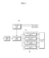
- FIG. 1 is a view illustrating a photon detecting and counting system, according to one or more embodiments.
- the photon detecting and counting system 100 may include a sensor unit 101, a switching unit 102, a control unit 103, a counting unit 104, and a buffer 105, for example.
- the sensor unit 101 receives optical signals and outputs electric signals corresponding to the received optical signals. For example, the sensor unit 101 detects photons and generates respective pulse currents corresponding to the detected photons. Such a sensor unit 101 may be implemented using a photo diode that generates current in response to light, for example.
- the sensor unit 101 may equally be a CCD or a photomultiplier, and the incident light could include light of different wavelengths, including X-ray photons, as only an example. Additionally, the sensor unit may include plural photon detectors, such as respectively detecting photons for different sensors.
- the switching unit 102 selectively provides the electric signals or charges output from the sensor unit 101 to the appropriate counter within the counting unit 104.
- the counting unit 104 may include a first counter 104-1, a second counter 104-2, a third counter 104-3, and a fourth counter 104-4, for example.
- the switching unit 102 selectively provides the electric signal or charge from the sensor unit 101 to any one of the counters 104-1, 104-2, 104-3 and 104-4 that is not in a dead time, e.g., according to one or more control signals of the control unit 103.
- dead time is a period of time during which the photon detection system is in operation with a counting of a photon for a previously provided pulse signal, such that a pile up may occur if the photon detection system were to begin to process subsequent photon pulse signals unless the original counting has been completed or at least the subsequent pulse signal will not overlap with the previous pulse signal.
- the switching unit 102 prevents the electric signal or charge from being provided to a counter currently in operation and provides the electric signal or charge to another counter, e.g., a counter that is in a standby status.
- a counter that is in a standby status.
- One or more mechanisms for providing electric signals or charges from the sensor unit 101 to the counter not in dead time will be described in greater detail below.
- the counters 104-1, 104-2, 104-3 and 104-4 of the counting unit 104 are configured to count photons, for example.
- FIG. 2 is a view illustrating a counter, such as a counter of counting unit 104, according to one or more embodiments.
- the first counter 104-1 may include a converter 201, an amplifier 202, a discriminator 203, and a digital counter 204, for example, and each of the converter 201, amplifier 202, discriminator 203, and digital counter 204 may be configured to operate on an expected input voltage or current to count photons.
- the converter 201 converts received electric signals or charges into voltages or current. For example, if the sensor unit 101 generates an electric current or charge represented by a pulse signal, the converter 201 may convert the received electric current into a voltage. If the remainder of the signal processing does not need such a conversion, then the converter can be excluded from the counter.
- the amplifier 202 may amplify the outputs of the converter 201. If the provided electric signal or charge from the sensor unit 101 is of a sufficient detectable level then the amplifier may not be needed. However, when detecting photons through a photomultiplier, for example, the generated pulse signals at the anode of the photomultiplier may typically still need amplification for adequate and accurate discrimination and counting.
- the discriminator 203 may serve to review the amplified pulse signal for a lower threshold, e.g., with pulse signals that are greater than this threshold being identified as representing photons.
- the discriminator 203 may also discriminate the amplified pulse signal for an upper threshold for potentially discriminating out pulse signals that are too high.
- the output of the discriminator 203 may merely be a constant "HIGH” or "LOW” signal, e.g., representing whether the amplified pulse signal fell between the lower and upper thresholds, or at least whether the amplified pulse was above the lower threshold.
- the discriminator 203 compares a received amplified voltage or current with a predetermined reference voltage or predetermined current, as the thresholds, such that a digital comparative value is output.
- the output of the discriminator 203 may be a constant TTL logic level or CMOS level, for example, though alternative output levels are available, and the output of the discriminator 203 may alternatively be a rectangular pulse, for example, adequate for the subsequent digital counter 204 to count.
- the discriminator 203 or other reviewing stages of the counter 104 may provide the buffer 105 with additional information regarding each pulse signal that has been discerned to be a photon count, such as pulse amplitude, pulse width, dissipation time, frequency, etc., as only examples, that may be analyzed for additional information regarding the detected photons.
- the sensor unit 101 may detect a photon and generate a pulse current in response to the detected photon.
- the pulse current may be converted into a pulse voltage through the converter 201.
- the converted pulse voltage may be amplified by the amplifier 202 and then input into the discriminator 203.
- the discriminator 203 may then compare the received amplified voltage with a predetermined reference voltage and output a constant binary 'HIGH' or 'LOW' signal based on the comparison result. For example, if a difference between the amplified voltage and the reference voltage exceeds at least the lower threshold value, the discriminator 203 outputs '1', and if a difference between the amplified voltage and the reference voltage is below the lower threshold value, the discriminator 203 outputs '0'.
- the output of the discriminator 203 may be the constant "HIGH” or “LOW” signals or digital output of "1" or “0", for example.
- a pulse shaper may follow the discriminator 203, or be provided with the discriminator 203 or the digital counter 204, to generate a rectangular pulse, for example, that may be preferable for the counting by the digital counter 204.
- the digital counter 204 may thus count the digital comparative value output from the discriminator 203, and increment the count every time a new binary "HIGH" signal from the discriminator 203 is detected. For example, in the above case, the digital counter 204 counts outputs of '1' generated by the discriminator 203. In one or more embodiments, upon completion of the count the discriminator 203 may change the corresponding digital comparative value back to a "LOW" level. Based upon this "LOW" level, the control unit 103 may discern that the corresponding counter 104 is available for a next pulse signal.
- the output of the discriminator 203 may control the application of a corresponding flag signal that is provided to the control unit 103.
- the flag signals represent the respective availability or operational state of the counters 104-1, 104-2, 104-3 and 104-4, and may be input into the control unit 103, or in one or more embodiments directly provided to the switching unit 102.
- the discriminator 203 may accordingly notify the control unit whenever a pulse signal has been reviewed, the counter 104 is ready for a new pulse signal, or merely indicate when no currently applied pulse signal meets the lower threshold.
- the flag may be provided to the control unit 103 to indicate that the counter 104-1, for example, is at a stage where a new electric signal or charge from the sensor unit 101 can be counted without causing a pile up.
- the flag can merely be the output of the discriminator 203, e.g., the constant "HIGH” or "LOW” signal.
- the control unit 103 may be configured to accept either of the constant "HIGH” or "LOW” signals or any other signal that would indicate the readiness for a new pulse signal of the respective counter 104.
- the control unit 103 controls the switching unit 102 such that the electric signal or charge provided by the sensor unit 101 is selectively provided to one of the counters 104-1, 104-2, 104-3 and 104-4 that is not in dead time, e.g., based on the respective flag signals.
- Flag 1 from counter 104-1 is '1'
- Flag 2 from counter 104-2 Flag 3 from counter 104-3
- Flag 4 from counter 104-4 are all '0'
- the first counter 104-1 will be considered to be in an operational state
- the remaining 104-2, 104-3 and 104-4 will be considered to be in a standby state.
- the control unit 103 controls the switching unit 102 such that the output of the sensor unit 101 is electrically connected to one of the second counter 104-2, the third counter 104-3 and the fourth counter 104-4.
- the flag signal and the digital comparative value have been described as being set as a value '1' or '0', but are not limited thereto.
- the flag signal and the digital comparative value may be set using other values.
- the flags are not required to be provided solely by the output of each discriminator 203 to each counter 104, but may be provided by other dead time determinative portions of each counter 104. Additional status information for each discriminator 203 may be available and provided to the control unit 103 and/or the buffer 105, for example, such as additional information for additional and/or alternative thresholds in amplitude and other characteristics of the discriminated pulse signal.
- flag signals may not necessarily merely represent a same constant "HIGH” or "LOW” signal, for example, provided by each discriminator 203 to each digital counter 204, but may be caused to be pulsed "THIGH” or "LOW” status signals, as only an example, through additional circuitry.
- the buffer 105 may store the counting result of the counters 104-2, 104-3, and 104-4.
- An image processing unit may be provided at the end of the buffer 105, and included with the system of the buffer in one or more embodiments, to image the counting result.
- a Multi Energy Discriminator system may be included with the photon counting system of FIG. 1 , and may analyze information of each reviewed counted pulse signal stored in the buffer 105.
- the multi energy system may illustrate an acquired high energy image with high contrast, such as when X-rays are detected for a high contrast X-ray image.
- An embodiment with the Multi Energy Discriminator is shown in FIGS. 5A and 5B , and will be discussed in greater detail below.
- each of the counters 104-1, 104-2, 104-3, and 104-4 notifies the control unit 103 of its current state, e.g., dead time state, through the flag signal.
- the control unit 103 and the switching unit 102 allow the electric signals or charges from the sensor unit 101 to be selectively provided along an electrical path enabling a normal operation of the photon detecting and counting system 100 based on the flag signal, thereby removing the pulse pile-up phenomenon due to dead time.
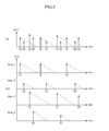
- FIG. 3 is a view illustrating input signals of a photon counting system, according to one or more embodiments.
- Reference numeral 301 represents outputs of the sensor unit 101
- reference numeral 302 represents pulse signals input to the counters 104-1, 104-2, 104-3 and 104-4.
- Pass_1 represents the input of the first counter 104-1
- Pass_2 represents the input of the second counter 104-2
- Pass_3 represents the input of the third counter 104-3
- Pass_4 represents the input of the fourth counter 104-4.
- FIG. 3 represent pulse voltages generated by detected photons, i.e., as provided by the sensor unit 101, and the time elapsed under the illustrated dashed lines extending down and right from the tip of each arrow represents dead time generated when photons are counted.
- the dead time represents the time the corresponding counter should potentially not be available, to prevent pile up.
- This dead time may also include the time it takes for each electric signal or charge provided by the sensor unit 101 to sufficiently dissipate, i.e., so there is a desirably minimum charge influence between applied electric signals or charges. This can be seen in FIG.
- the energy level of the charge provided by the photomultiplier may also control the dead time, as the dissipation time for larger charges is greater than smaller charges.
- the dead times may not be predicted solely by estimating the processing time of the counting unit 104.
- each of the discriminators 203 may be beneficial to more accurately count provided electric signals or charges provided by the sensing unit 101 without pile up, noting that alternative portions of the counters 104, or even buffer 105, could provide this status indication of whether the respective counter 104 is available for a next pulse signal without generating a pile up, or most probable to not generate a pile up if a new pulse signal were to be applied to the same counter 104.
- the electric signals or charges 301 output by the sensor unit 101 may be distributed through the switching unit 102 similarly to the respective counter 104 inputs, as pulse signals 302, based on stand by statuses of each of the counters. For example, in the case that the first counter 104-1 processes the pulse 1, the first counter 104-1 counts the pulse 1 and provides the control unit 103 with a flag signal indicating that the first counter 104-1 is in operation. The control unit 103 recognizes that the first counter 104-1 is in operation and the remaining counters 104-2, 104-3 and 104-4 are on standby based on the received respective flag signals.
- the control unit 103 transmits a control signal to the switching unit 102 such that one of the counters 104-2, 104-3 and 104-4, that is any counter except for the first counter 104-1, processes the pulse 2.
- the pulse 2 may be input into the second counter 104-2.
- the second counter 104-2 provides the control unit 103 with a flag signal indicating that the second counter 104-2 is in operation, and the control unit 103 controls the switching unit 102 based on the flag signal transmitted from the second counter 104-2.
- the use of the counters 104 are not limited thereto and any one of the counters 104 that is not in dead time may be selected at random for use. For example, if the photon counting system has a plurality of counters 104 not in dead time, a counter 104 that has not been in operation for the longest time may be selected for use, or if all counters 104 are in dead time then a counter 104 that has been in operation for the longest time may be selected for use or the newly available pulse signal from the sensor unit 101 may be restricted or eliminated, noting that alternative schedules for selecting counters are equally available.
- the counters 104 are not required to be the same, and each may different characteristics or features.
- the flags for the respective status of each of the counters may be provided from the discriminator 203 in one counter 104 and provided from another portion in another counter 104.
- FIG. 4 is a flowchart illustrating a photon counting method, according to one or more embodiments. A flow of the photon counting method will be described in conjunction with FIG. 1 , though embodiments are not limited to the same system.
- a controller may receive respective flags or indicators from one or more of counters that are capable of receiving an output electric signal or charge from a photon detector, in operation 401.
- he control unit 103 may receive a flag signal from each of the counters 104-1, 104-2, 104-3 and 104-4.
- the flag signal may indicate the availability of each of the counters 104-1, 104-2, 104-3 and 104-4 for a counting of a photon.
- the availability for counting a photon may be based on several factors for each counter 104, including the factor of whether the counter 104 could count a photon without pile up, for example.
- the flag signal is implemented using the digital comparative value of the discriminator 203 provided in each of the counters 104-1, 104-2, 104-3 and 104-4.
- a select one, for example, of the counters may then be selected to be electrically connected with the photon detector or be provided an electric signal or charge derived from the photon detector, in operation 402.
- the control unit 103 selects at least one of the counters, which is not in dead time, using the received flag signal.
- the control unit 103 may designate a counter outputting a flag signal '0' as a counter not in dead time and may provide the electric signal or charge from the sensor unit to the counter not in dead time.
- the provided electric signal or charge may be provided to more than one counter.
- the amplifiers 202 or discriminators 203 of the respective counters 104 may need to be variably controlled to accommodate the corresponding shared pulse signal.
- the control unit 101 may further control which counter 104 should receive which electrical signal or charge.
- the selected one or more counters selected for connection with the photon detector or provided the electric signal or charge derived from the photon detector may be electrically connected with the electric signal or charge, in operation 402.
- the control unit 103 may control the switching unit 102 such that the electric signal or charge corresponding to one or more photons detected by the sensor unit 101 is provided to the selected counter which is not in dead time.
- the switching unit 102 may switch a signal transmission path such that the electric signal or charge is transmitted to a counter, which is not in operation, according to a control signal of the control unit 103.
- FIGS. 5A and 5B illustrate photon detection and counting systems, according to one or more embodiments.
- a sensor 501 provides the electric signal or charge to one or more select photon counter blocks 504 through a switching module 502.
- the switching module 502 may include separate switches that selectively open or close to permit provision of the output of the sensor 501 to the respective photon counter block 504.
- FIG. 5B collectively illustrates the plural photon blocks 504 as an adaptive processing system.
- each photon counter block 504 further illustrates each photon counter block 504 as having a voltage to current converter 511, a main amplifier 512, a discriminator/shaper 513, and a counter 514, with the status flags being derived from the same output signal of the discriminator/shaper 513 that is provided to each counter 514.
- the flag signals are provided to the Adaptive Switching Controller 503, which controls the provision of the output of the sensor 501 to select photon counter blocks 504 through the switching module 502.
- the flags may be output to the Adaptive Switching Controller 503 from the discriminator/shaper 513 as the constant "HIGH” or "LOW" voltages, for example, before the discriminator/shaper 513 generates the shaped pulse that is output to counter 514.
- the "HIGH" or "LOW” signal from the discriminator/shaper 513 may be directly applied to the switching module 502.
- the switching module 502, Adaptive Switching Controller 503, photon counter block 504, and buffer 505 may be referred to as an Adaptive Photon Processing system.
- the systems of FIGS. 5A and 5B further illustrate a Multi Energy Discriminator system 520, with additional comparators 522 and multi energy counters 524 that represent a processed pulse charge analysis and classification.
- the processed pulse charge signals, as an output of the buffer 505 may be classified according to their amplitudes by the multi comparators, and then the classified signal's counts may be visualized as gray level images on an included display.
- an output of the discriminator/shaper 513 may be a constant TTL logic level or CMOS level, for example, though alternative output levels are available, for indicating the status of each photon counter block 504 and a shaped rectangular pulse, for example, adequate for the subsequent counter 514 to count the detected photon.
- the discriminator/shaper 513 or other reviewing stages of the photon counter block 504, for example, may provide the buffer 505 with additional information regarding each pulse signal that has be discerned to be a photon count, such as pulse amplitude, pulse width, dissipation time, frequency, etc., as only examples.
- an image processing unit may be included with the system of a Multi Energy Discriminator analyzing information of each reviewed counted pulse signal stored in the buffer 505, such as photon count information provided by the photon counter blocks. Based upon analysis by the multi energy discrimination, the multi energy system may illustrate an acquired high energy image with high contrast on an include display or store corresponding image data in a memory, such as when X-rays are acquired for a high contrast X-ray image.
- embodiments can also be implemented through computer readable code/instructions in/on a non-transitory medium, e.g., a computer readable medium, to control at least one processing device, such as a processor or computer, to implement any above described embodiment.
- a non-transitory medium e.g., a computer readable medium
- the medium can correspond to any defined, measurable, and tangible structure permitting the storing and/or transmission of the computer readable code.
- the media may also include, e.g., in combination with the computer readable code, data files, data structures, and the like.
- One or more embodiments of computer-readable media include magnetic media such as hard disks, floppy disks, and magnetic tape; optical media such as CD ROM disks and DVDs; magneto-optical media such as optical disks; and hardware devices that are specially configured to store and perform program instructions, such as read-only memory (ROM), random access memory (RAM), flash memory, and the like.
- Computer readable code may include both machine code, such as produced by a compiler, and files containing higher level code that may be executed by the computer using an interpreter, for example.
- the media may also be a distributed network, so that the computer readable code is stored and executed in a distributed fashion.
- the processing element could include a processor or a computer processor, and processing elements may be distributed and/or included in a single device.
Landscapes
- Physics & Mathematics (AREA)
- General Physics & Mathematics (AREA)
- Spectroscopy & Molecular Physics (AREA)
- Health & Medical Sciences (AREA)
- Life Sciences & Earth Sciences (AREA)
- High Energy & Nuclear Physics (AREA)
- Molecular Biology (AREA)
- Measurement Of Radiation (AREA)
- Photometry And Measurement Of Optical Pulse Characteristics (AREA)
Applications Claiming Priority (1)
| Application Number | Priority Date | Filing Date | Title |
|---|---|---|---|
| KR1020090076514A KR101616056B1 (ko) | 2009-08-19 | 2009-08-19 | 광자 계수 장치 및 방법 |
Publications (2)
| Publication Number | Publication Date |
|---|---|
| EP2293110A2 true EP2293110A2 (fr) | 2011-03-09 |
| EP2293110A3 EP2293110A3 (fr) | 2015-01-21 |
Family
ID=43502857
Family Applications (1)
| Application Number | Title | Priority Date | Filing Date |
|---|---|---|---|
| EP10173420.0A Withdrawn EP2293110A3 (fr) | 2009-08-19 | 2010-08-19 | Système et procédé de comptage de photons |
Country Status (5)
| Country | Link |
|---|---|
| US (1) | US8319187B2 (fr) |
| EP (1) | EP2293110A3 (fr) |
| JP (1) | JP2011043501A (fr) |
| KR (1) | KR101616056B1 (fr) |
| CN (1) | CN101996344B (fr) |
Cited By (1)
| Publication number | Priority date | Publication date | Assignee | Title |
|---|---|---|---|---|
| US11237047B2 (en) | 2017-09-20 | 2022-02-01 | Olympus Corporation | Optical measurement device, optical measurement method, and scanning microscope |
Families Citing this family (13)
| Publication number | Priority date | Publication date | Assignee | Title |
|---|---|---|---|---|
| EP2490441A1 (fr) * | 2011-02-16 | 2012-08-22 | Paul Scherrer Institut | Système détecteur de comptage à photon unique doté d'une architecture de compteur améliorée |
| KR101871361B1 (ko) | 2011-11-01 | 2018-08-03 | 삼성전자주식회사 | 고해상도 및 고대조도 영상을 동시에 생성하기 위한 광자 계수 검출 장치 및 방법 |
| US9177987B2 (en) | 2012-10-12 | 2015-11-03 | Samsung Electronics Co., Ltd. | Binary CMOS image sensors, methods of operating same, and image processing systems including same |
| US9432604B2 (en) | 2012-10-12 | 2016-08-30 | Samsung Electronics Co., Ltd. | Image sensor chips |
| KR20150024721A (ko) | 2013-08-27 | 2015-03-09 | 삼성전자주식회사 | 전압의 초기화 시점을 적응적으로 결정하는 방법 및 장치. |
| US9210350B2 (en) * | 2013-12-09 | 2015-12-08 | Omnivision Technologies, Inc. | Low power imaging system with single photon avalanche diode photon counters and ghost image reduction |
| KR101684448B1 (ko) * | 2014-01-07 | 2016-12-08 | 삼성전자주식회사 | 방사선 디텍터, 그에 따른 단층 촬영 장치, 및 x 선 촬영 장치 |
| WO2015105314A1 (fr) | 2014-01-07 | 2015-07-16 | Samsung Electronics Co., Ltd. | Détecteur de rayonnement, son appareil d'imagerie par tomographie, et son appareil de détection de rayonnement |
| DE112015002679T5 (de) | 2014-06-06 | 2017-04-20 | Siemens Medical Solutions Usa, Inc. | Gammakamera-totzeitbestimmung in echtzeit unter verwendung langlebiger radioisotope |
| CN106054038B (zh) * | 2016-06-29 | 2019-01-15 | 南京理工大学 | 一种连通域标记的紫外单光子计数的方法 |
| JP6874714B2 (ja) * | 2018-02-22 | 2021-05-19 | 株式会社豊田中央研究所 | 光検出器及び光学測距装置 |
| CN114185057B (zh) * | 2021-11-10 | 2024-05-17 | 华为技术有限公司 | 一种探测方法、装置和终端 |
| US12287437B2 (en) * | 2022-01-19 | 2025-04-29 | Analog Devices, Inc. | Quantitative pulse selection for photon-counting computed tomography scanning systems |
Family Cites Families (13)
| Publication number | Priority date | Publication date | Assignee | Title |
|---|---|---|---|---|
| IT1198771B (it) | 1984-01-27 | 1988-12-21 | Mario Alcidi | Metodo e dispositivo per l'abbattimento dell'effetto pile-up in contatori a scintillazione |
| JPS63127180A (ja) * | 1986-11-17 | 1988-05-31 | Nippon X-Ray Kk | X線分析装置 |
| EP0410828A3 (en) | 1989-06-28 | 1993-03-17 | Schlumberger Limited | Dead time correction and regulation method and apparatus for nuclear spectroscopy |
| JPH0619455B2 (ja) * | 1989-08-15 | 1994-03-16 | 株式会社島津製作所 | 放射線測定装置 |
| CN1124496C (zh) * | 2000-08-24 | 2003-10-15 | 中国科学院大气物理研究所 | 激光雷达用的具有嵌入系统和门控功能的单光子计数器 |
| US20030228703A1 (en) * | 2002-04-05 | 2003-12-11 | The Regents Of The University Of Michigan | Fluorescence resonance energy transfer quantitation and stoichiometry in living cells |
| JP4346476B2 (ja) * | 2004-03-08 | 2009-10-21 | 株式会社堀場製作所 | 粒径分布測定装置 |
| US7966155B2 (en) | 2004-06-04 | 2011-06-21 | William K. Warburton | Method and apparatus for improving detection limits in x-ray and nuclear spectroscopy systems |
| DE102006029184A1 (de) | 2006-06-24 | 2007-12-27 | Friedrich-Alexander-Universität Erlangen-Nürnberg | Photonendetektor |
| JP2010500597A (ja) * | 2006-08-14 | 2010-01-07 | コーニンクレッカ フィリップス エレクトロニクス エヌ ヴィ | 計数電子装置を有する放射線検出器 |
| WO2008050283A2 (fr) * | 2006-10-25 | 2008-05-02 | Koninklijke Philips Electronics N.V. | Appareil, dispositif d'imagerie et procédé pour détecter un rayonnement de rayons x |
| US8237128B2 (en) * | 2006-12-13 | 2012-08-07 | Koninklijke Philips Electronics N.V. | Apparatus, imaging device and method for counting X-ray photons |
| US7430481B2 (en) | 2007-01-12 | 2008-09-30 | R. J. Lee Group, Inc. | Methods for detecting and analyzing piled-up X-rays in an X-ray spectrometry system |
-
2009
- 2009-08-19 KR KR1020090076514A patent/KR101616056B1/ko not_active Expired - Fee Related
-
2010
- 2010-08-18 JP JP2010182967A patent/JP2011043501A/ja active Pending
- 2010-08-18 US US12/805,759 patent/US8319187B2/en not_active Expired - Fee Related
- 2010-08-19 CN CN201010257329.8A patent/CN101996344B/zh not_active Expired - Fee Related
- 2010-08-19 EP EP10173420.0A patent/EP2293110A3/fr not_active Withdrawn
Non-Patent Citations (1)
| Title |
|---|
| None |
Cited By (1)
| Publication number | Priority date | Publication date | Assignee | Title |
|---|---|---|---|---|
| US11237047B2 (en) | 2017-09-20 | 2022-02-01 | Olympus Corporation | Optical measurement device, optical measurement method, and scanning microscope |
Also Published As
| Publication number | Publication date |
|---|---|
| KR20110018995A (ko) | 2011-02-25 |
| KR101616056B1 (ko) | 2016-04-28 |
| EP2293110A3 (fr) | 2015-01-21 |
| CN101996344B (zh) | 2014-06-18 |
| JP2011043501A (ja) | 2011-03-03 |
| US20110042573A1 (en) | 2011-02-24 |
| US8319187B2 (en) | 2012-11-27 |
| CN101996344A (zh) | 2011-03-30 |
Similar Documents
| Publication | Publication Date | Title |
|---|---|---|
| US8319187B2 (en) | System and method counting photons | |
| US20130028382A1 (en) | Method for detecting the true coincidence of two charge pulses on adjacent picture elements, x-ray detector and x-ray image recording apparatus | |
| RU2695638C2 (ru) | Способ и система раннего оповещения об отказе в вентиле преобразователя | |
| EP2092369B1 (fr) | Appareil et procédé pour compter les photons de rayons x | |
| EP3341755B1 (fr) | Dispositif et procédé de comptage de photons | |
| US8415635B2 (en) | Particle-counting apparatus with pulse shortening | |
| US8866094B2 (en) | Radiation detector | |
| US20190086561A1 (en) | Configurable Analog-to-Digital Converter and Processing for Photon Counting | |
| US9784784B2 (en) | Signal processing device and method and radiation detecting device for a pileup phenomenon | |
| US20220342090A1 (en) | Xrf analyzer with improved resolution by using micro-reset | |
| US9188552B2 (en) | X-ray spectrometer and sample analyzer | |
| JPH0627828B2 (ja) | 位置検出器 | |
| JP6578817B2 (ja) | 信号処理装置及び放射線測定装置 | |
| US20140114596A1 (en) | Radiation measuring apparatus | |
| US20250015806A1 (en) | Method for Operating a Circuit Arrangement and Circuit Arrangement | |
| US12468055B2 (en) | Energy bin event counting system | |
| US20250284011A1 (en) | Photon counting detector and photon counting method | |
| JPH09189604A (ja) | 計数禁止時間の決定方法、及び光子計数装置 | |
| JPH04270986A (ja) | X線信号処理回路 | |
| WO2023119934A1 (fr) | Procédé de détermination de valeur seuil, programme de détermination de valeur seuil, dispositif de détermination de valeur seuil, système d'identification de nombre de photons, procédé d'identification de nombre de photons et programme de traitement d'identification de nombre de photons | |
| KR101844022B1 (ko) | 멀티-에너지 방사선에 포함된 광자의 에너지 대역을 구분하기 위한 장치 및 방법 | |
| EP2924422A1 (fr) | Spectromètre par rayons X et circuit électronique de diagnostique |
Legal Events
| Date | Code | Title | Description |
|---|---|---|---|
| PUAI | Public reference made under article 153(3) epc to a published international application that has entered the european phase |
Free format text: ORIGINAL CODE: 0009012 |
|
| AK | Designated contracting states |
Kind code of ref document: A2 Designated state(s): AL AT BE BG CH CY CZ DE DK EE ES FI FR GB GR HR HU IE IS IT LI LT LU LV MC MK MT NL NO PL PT RO SE SI SK SM TR |
|
| AX | Request for extension of the european patent |
Extension state: BA ME RS |
|
| RAP1 | Party data changed (applicant data changed or rights of an application transferred) |
Owner name: SAMSUNG ELECTRONICS CO., LTD. |
|
| PUAL | Search report despatched |
Free format text: ORIGINAL CODE: 0009013 |
|
| AK | Designated contracting states |
Kind code of ref document: A3 Designated state(s): AL AT BE BG CH CY CZ DE DK EE ES FI FR GB GR HR HU IE IS IT LI LT LU LV MC MK MT NL NO PL PT RO SE SI SK SM TR |
|
| AX | Request for extension of the european patent |
Extension state: BA ME RS |
|
| RIC1 | Information provided on ipc code assigned before grant |
Ipc: G01T 1/17 20060101AFI20141218BHEP |
|
| STAA | Information on the status of an ep patent application or granted ep patent |
Free format text: STATUS: THE APPLICATION IS DEEMED TO BE WITHDRAWN |
|
| 18D | Application deemed to be withdrawn |
Effective date: 20150722 |