EP2293182A2 - Dispositif d'affichage multi-images et dispositif d'affichage d'images - Google Patents
Dispositif d'affichage multi-images et dispositif d'affichage d'images Download PDFInfo
- Publication number
- EP2293182A2 EP2293182A2 EP10007994A EP10007994A EP2293182A2 EP 2293182 A2 EP2293182 A2 EP 2293182A2 EP 10007994 A EP10007994 A EP 10007994A EP 10007994 A EP10007994 A EP 10007994A EP 2293182 A2 EP2293182 A2 EP 2293182A2
- Authority
- EP
- European Patent Office
- Prior art keywords
- unit
- image signal
- image
- display
- apparatuses
- Prior art date
- Legal status (The legal status is an assumption and is not a legal conclusion. Google has not performed a legal analysis and makes no representation as to the accuracy of the status listed.)
- Withdrawn
Links
Images

Classifications
-
- G—PHYSICS
- G06—COMPUTING OR CALCULATING; COUNTING
- G06F—ELECTRIC DIGITAL DATA PROCESSING
- G06F3/00—Input arrangements for transferring data to be processed into a form capable of being handled by the computer; Output arrangements for transferring data from processing unit to output unit, e.g. interface arrangements
- G06F3/14—Digital output to display device ; Cooperation and interconnection of the display device with other functional units
- G06F3/1423—Digital output to display device ; Cooperation and interconnection of the display device with other functional units controlling a plurality of local displays, e.g. CRT and flat panel display
- G06F3/1446—Digital output to display device ; Cooperation and interconnection of the display device with other functional units controlling a plurality of local displays, e.g. CRT and flat panel display display composed of modules, e.g. video walls
-
- G—PHYSICS
- G09—EDUCATION; CRYPTOGRAPHY; DISPLAY; ADVERTISING; SEALS
- G09G—ARRANGEMENTS OR CIRCUITS FOR CONTROL OF INDICATING DEVICES USING STATIC MEANS TO PRESENT VARIABLE INFORMATION
- G09G5/00—Control arrangements or circuits for visual indicators common to cathode-ray tube indicators and other visual indicators
- G09G5/003—Details of a display terminal, the details relating to the control arrangement of the display terminal and to the interfaces thereto
- G09G5/006—Details of the interface to the display terminal
-
- G—PHYSICS
- G09—EDUCATION; CRYPTOGRAPHY; DISPLAY; ADVERTISING; SEALS
- G09G—ARRANGEMENTS OR CIRCUITS FOR CONTROL OF INDICATING DEVICES USING STATIC MEANS TO PRESENT VARIABLE INFORMATION
- G09G2330/00—Aspects of power supply; Aspects of display protection and defect management
- G09G2330/02—Details of power systems and of start or stop of display operation
- G09G2330/021—Power management, e.g. power saving
- G09G2330/022—Power management, e.g. power saving in absence of operation, e.g. no data being entered during a predetermined time
Definitions
- the present invention relates to an image display apparatus used in combination with other image display apparatuses, and to a multi-image display apparatus comprised by a plurality of said image display apparatus.
- multi-image display apparatuses comprised by a plurality of image display apparatuses are becoming common.
- the multi-image display apparatus can display a large single image using a plurality of image display apparatuses.
- the multi-image display apparatus can display same images, such as odds offered by a bookmaker, on a plurality of image display apparatuses.
- Some of the multi-image display apparatuses employ so-called daisy chain connection in which image display apparatuses are connected in series.
- daisy chain connection since image signals can be transmitted sequentially from an upstream image display apparatus to a downstream image display apparatus, the structure of the multi-image display apparatus can be simplified (e.g. wiring).
- each of the image display apparatuses outputs an image signal adjusted by its driver unit to the subsequent image display apparatus in order to reduce the deterioration of frequency characteristics of the image signal transmitted to the subsequent apparatuses.
- the driver unit In order to operate the driver unit, it requires an electric power of 0.1 to 1 W, for example.
- the image display apparatus When the image display apparatus is in a displaying state, it consumes a lot of power and thus the power consumption in the driver unit is not a big problem since the power consumption in the driver is small compared to the total consumption of the display apparatus.
- the image display apparatus is in a standby state, since the ratio of power consumption in the driver unit to total power consumption is large, whether or not the driver unit operates is a large issue. In particular, it is required that the power consumption is 1W or lower during the standby mode, and it is difficult to meet this requirement when the driver unit is operated.
- a multi-image display apparatus includes a plurality of image display apparatuses connected in series, wherein each of the image display apparatuses comprises:
- An image display apparatus includes:
- FIG. 1 is a block diagram illustrating a structural example a multi-image display apparatus.
- the multi-image display apparatus denoted by M, includes a plurality of image display apparatuses D.
- the apparatuses D are individually denoted by Dn (n represents a natural number), and an apparatus Dn to which a larger n is suffixed is located further downstream among a chain of serially connected apparatuses D.
- the apparatus M of FIG. 1 has nine apparatuses D1 to D9, three apparatuses in the horizontal direction and three apparatuses in the vertical direction.
- Each of the apparatuses D is connected by signal lines S.
- the signal lines S are individually denoted by Sn, and a signal line Sn to which a larger n is suffixed is connected to an apparatus Dn that is located further downstream.
- the signal line which connects the apparatuses Dn and Dn+1 and which inputs an image signal outputted from the apparatus Dn to the apparatus Dn+1 is specially denoted by Sn.
- the apparatus D9 which is at the tail end of the chain of apparatuses D in the apparatus M of FIG. 1 , does not have a signal line S for outputting an image signal to the subsequent apparatus.
- the apparatus M therefore has eight signal lines, S1 to S8.
- an image signal outputted from an image signal outputting apparatus E is inputted.
- the apparatus D1 outputs the inputted image signal to its subsequent apparatus D2 through the signal line S1, irrespective of whether or not the image signal is to be displayed by the apparatus D1.
- the apparatus Dn outputs an image signal inputted through the signal line Sn-1 to its subsequent apparatus Dn+1 through the signal line Sn, irrespective of whether or not the image signal is to be displayed by the apparatus Dn.
- the image signal is thus transmitted and reaches the apparatus D9 which is at the tail end of the chain of apparatuses D. The operation of the individual apparatus Dn is described later.
- an image signal outputted from the image signal outputting apparatus E is inputted to each of the apparatuses D1 to D9.
- Each of the apparatuses D1 to D9 displays an entire portion of respective image signal (a multi-screen mode) or different portion of the image signal (a full-screen mode).
- the image signal outputting apparatus E may be, for example, a receiving apparatus that receives television broadcasting, a reproducing apparatus that outputs an image recorded on a recording medium, or a personal computer.
- FIG. 2 is a block diagram illustrating a structural example of the image display apparatus.
- the apparatus Dn of FIG. 2 is the apparatus employed for a middle part of the chain of apparatuses D in the apparatus M of FIG. 1 (i.e. the apparatus of Fig.2 is not the one employed for the head or the tail end of the chain).
- the apparatus Dn includes: an input terminal Ti to which the signal line Sn-1 is connected and an image signal is inputted; a terminating resistor R which terminates an image signal inputted to the input terminal Ti; a termination switching unit Ct which switches a enabled/disabled status of the connection between the input terminal Ti and the resistor R; a signal processing unit P which performs given processing on an image signal inputted to the input terminal Ti; a display unit L which displays an image signal processed by the unit P; a driver unit A which adjusts the electric current value of an image signal inputted to the terminal Ti and outputs the adjusted image signal; an output switching unit Co which selectively outputs an image signal which is adjusted by the driver unit A or an image signal which is not adjusted by the driver unit A; an output terminal To which receives an image signal outputted from the unit Co and outputs the received image signal to its connected signal line Sn; and a control unit X which controls switching in the unit Co and in the unit Ct.
- the terminating resistor R has a given resistance value (for example, 75 ⁇ ) in order to make an image signal displayed by an appropriate voltage value through impedance matching. If the resistance value is altered to the other value, the alteration distorts the waveform of the image signal and an image displayed by the display unit L deteriorates.
- One end N1 of the resistor R is grounded and the other end N2 is connected to the unit Ct. By using the unit Ct, connection or disconnection between the terminal Ti and the other end N2of the resistor R is switched.
- the signal processing unit P performs, when the apparatus M displays in the multi-screen mode, processing such as scaling (enlargement or reduction) or luminance adjustment on an inputted image signal, and outputs an image signal adapted for the display unit L.
- processing such as scaling (enlargement or reduction) or luminance adjustment on an inputted image signal
- the unit P further performs processing of obtaining a predetermined portion from the image signal, in addition to the processing executed in the multi-screen mode.
- the display unit L is constituted by a liquid crystal panel, for example, and displays an image signal outputted from the unit P.
- the driver unit A performs an adjustment of an inputted image signal such that the current value of the image signal becomes a predetermined value, and then outputs the image signal.
- the frequency characteristics of the image signal deteriorate when the signal is transmitted through a plurality of signal lines S and apparatuses D.
- the image signal is a high-resolution signal (which includes a fairly large high-frequency components, for example, Ultra Extended Graphics Array (UXGA))
- UXGA Ultra Extended Graphics Array
- none of the signal lines S is connected to the input terminal Ti and, instead, a signal line which transmits an image signal outputted from the image signal outputting apparatus E is connected.
- the apparatus D9 at the tail end of the chain of apparatuses D none of the signal lines is connected to the output terminal To and no image signal is outputted from the apparatus D9.
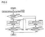
- FIG. 3 is a flow chart illustrating an example of switching operation of the output switching unit included in the above-described image display apparatus.
- the control unit X first acquires apparatus information (STEP 1).
- the apparatus information is, for example, information indicating the state of the apparatus Dn (displaying state or standby state) and information indicating an instruction to switch the states.
- control unit X determines whether the apparatus Dn is in a standby state or a displaying state based on the apparatus information acquired in STEP 1 (STEP 2).
- a switching control is performed such that the unit Co operates as a through-output mode, where the unit Co outputs an image signal inputted directly from the input terminal Ti (STEP 3).
- the unit Co is set to the through-output mode in STEP 3, power is not supplied to the driver unit A and thus the unit A is shut down.
- control unit X determines whether or not an instruction to make the apparatus Dn in a displaying state is inputted, based on the apparatus information acquired in STEP 1 (STEP 4). When it is determined that the instruction is displaying state not inputted (NO in STEP 4), the switching operation is terminated. In this case, the apparatus Dn is in a standby state and the unit Co is in the through-output mode.
- the control unit X performs the switching control such that the unit Co outputs an image signal which is outputted from the driver unit A (i.e. the unit Co is in a driver unit output mode) (STEP 5).
- control unit X determines whether or not the instruction to make the apparatus Dn in a standby state is inputted based on the apparatus information acquired in STEP 1 (STEP 6).
- the instruction is not inputted (NO in STEP 6)
- the switching operation is terminated.
- the apparatus Dn is in a displaying state and the unit Co is in the driver unit output mode.
- control unit X performs switching control such that the unit Co acts as the through-output mode (STEP 3).
- the output switching unit Co By switching the output switching unit Co as described above, it can reduce the deterioration of frequency characteristics of the image signal to be displayed on subsequent apparatuses D, by outputting an image signal which is adjusted by the driver unit A, when the apparatus is in a displaying state. Further, when the apparatus Dn is in a standby state, where the power consumption of the driver unit A is significant, it can reduce the power consumption by outputting an image signal that bypasses the driver unit A.
- the apparatus M may be structured such that a switching of the output switching unit Co for each apparatus Dn can be controlled at user's discretion. For instance, when the user prefers to reduce image quality deterioration in the subsequent apparatuses D, rather than to reduce power consumption, the apparatus M may be structured such that the unit Co operates as the driver unit output mode, even though the apparatus Dn is in a standby state. Specifically, for example, when the "power saving during standby mode" is ON, the state of the unit Co may be kept in the through-output state, and when the mode is OFF, the state of the unit Co may be kept in the driver unit output mode.
- the unit Co When the user prefers to reduce power consumption during a displaying state, it may be constituted such that the unit Co to operate as the through-output mode, even though the apparatus Dn is in a displaying state.
- the apparatus Dn when a "power save during displaying" mode is ON, for example, the apparatus Dn may keep the unit Co in through-output mode, whereas when the mode is OFF, the state of the unit Co may be switched as shown in FIG. 3 .
- the unit Co may be kept to the through-output mode since there are no apparatuses D subsequent to the apparatus D9.
- the unit Co may be set to through-output mode when the control unit X identifies the apparatus Dn as the tail end apparatus D9 based on the apparatus information acquired in STEP 1 of FIG. 3 .
- control unit X may determine whether or not the apparatus Dn is the tail end apparatus D9 based on other information such as arrangement information of the apparatuses within the apparatus M inputted by a user, information indicating whether or not signal lines S is connected to the terminal To, or information indicating whether or not the apparatuses D is connected with a signal lines S which is connected to the terminal To.
- the switching operation shown in FIG. 3 may be executed when an instruction (for example, an instruction to switch between the displaying state and the standby state, or an instruction to switch to the "power saving during standby" mode) from the user is inputted.
- an instruction for example, an instruction to switch between the displaying state and the standby state, or an instruction to switch to the "power saving during standby" mode
- the switching operation of the unit Ct is described next.
- the switching operation of the unit Ct is controlled by the control unit X and, for example, in a manner described below.
- the unit Ct is turned off (the other end N2 of the terminating resistor R and the terminal Ti are not connected).
- the unit Ct is turned on (the other end N2 and the input terminal Ti are connected).
- the terminating resistors R in the apparatus Dn and Dn+1 would be connected parallel.
- the resistance value decreases by half from the prescribed value 75 ⁇ (when two resistors R are connected in parallel), and as a result, the impedance matching becomes difficult.
- the unit Ct in all apparatuses D except for the tail end apparatus D9 it can inhibit the image signal waveform from being distorted, and can reduce the deterioration of images displayed on respective apparatuses D.
- the switching operation of the unit Ct is interlocked with the switching operation of the unit Co. Particularly, when the unit Co is set to through-output mode, the unit Ct is turned off, and when the unit Co is set to the driver unit output mode, the unit Ct is turned on. However, the unit Ct in the apparatus D9 is kept on regardless of the mode of unit Co.
- this structure can perform an impedance matching even when the unit Co is in the through-output mode, as well as in the first control example. Thus, it can prevent an image signal waveform from being distorted, and can inhibit the deterioration of images displayed on the respective apparatuses D.
- an image signal adjusted by the driver unit A becomes an image signal terminated by the terminating resistor R. Therefore, it can prevent the image signal outputted from the driver unit A from being over amplified.
- control unit X may determine whether or not the apparatus Dn is the tail end apparatus D9 based on other information such as arrangement information of image display apparatuses D within the apparatus M inputted by the user, information indicating whether or not the signal lines S is connected to the output terminal To, or information indicating whether or not the apparatuses D is connected to the signal lines S which is connected to the output terminal To.
- the terminating resistor R is applied to terminate an image signal.
- the other well-known terminating circuit may be employed.
- control unit X operations of the control unit X, the unit Ct, and the unit Co may be achieved by a microcomputer or other control devices. Further, all or some of functions implemented by this control device may be described as a program, and those functions may be realized by executing this program on a program executing apparatus (such as a computer).
- the present invention is not limited to the above-mentioned embodiments.
- the apparatus M of FIG. 1 and the apparatus Dn of FIG. 2 may be implemented solely by hardware or by a combination of hardware and software.
- a block diagram of a unit implemented by the software represents a function block diagram of the unit.
Landscapes
- Engineering & Computer Science (AREA)
- Theoretical Computer Science (AREA)
- Physics & Mathematics (AREA)
- General Physics & Mathematics (AREA)
- Multimedia (AREA)
- Human Computer Interaction (AREA)
- General Engineering & Computer Science (AREA)
- Computer Hardware Design (AREA)
- Controls And Circuits For Display Device (AREA)
- Transforming Electric Information Into Light Information (AREA)
- Control Of Indicators Other Than Cathode Ray Tubes (AREA)
Applications Claiming Priority (1)
| Application Number | Priority Date | Filing Date | Title |
|---|---|---|---|
| JP2009177302A JP5394161B2 (ja) | 2009-07-30 | 2009-07-30 | 画像表示装置 |
Publications (2)
| Publication Number | Publication Date |
|---|---|
| EP2293182A2 true EP2293182A2 (fr) | 2011-03-09 |
| EP2293182A3 EP2293182A3 (fr) | 2011-08-24 |
Family
ID=42667981
Family Applications (1)
| Application Number | Title | Priority Date | Filing Date |
|---|---|---|---|
| EP10007994A Withdrawn EP2293182A3 (fr) | 2009-07-30 | 2010-07-30 | Dispositif d'affichage multi-images et dispositif d'affichage d'images |
Country Status (3)
| Country | Link |
|---|---|
| US (1) | US20110025695A1 (fr) |
| EP (1) | EP2293182A3 (fr) |
| JP (1) | JP5394161B2 (fr) |
Families Citing this family (9)
| Publication number | Priority date | Publication date | Assignee | Title |
|---|---|---|---|---|
| JP5399847B2 (ja) * | 2009-10-02 | 2014-01-29 | 新日本無線株式会社 | 信号処理装置 |
| DE102013002435A1 (de) * | 2013-02-11 | 2014-08-14 | eyevis Gesellschaft für Projektions- und Grossbildtechnik mbH | Bildmodul für eine Bildwand |
| US20140236726A1 (en) * | 2013-02-18 | 2014-08-21 | Disney Enterprises, Inc. | Transference of data associated with a product and/or product package |
| CN103945254B (zh) * | 2014-03-26 | 2017-09-26 | 苏州佳世达电通有限公司 | 显示装置及定位该显示装置的显示画面的方法 |
| KR20160043477A (ko) | 2014-10-13 | 2016-04-21 | 삼성전자주식회사 | 디스플레이 장치, 복수의 디스플레이 장치를 포함하는 디스플레이 시스템 및 디스플레이 시스템의 제어 방법 |
| WO2016135881A1 (fr) * | 2015-02-25 | 2016-09-01 | Necディスプレイソリューションズ株式会社 | Système d'affichage, procédé d'affichage et programme d'affichage |
| US12007931B2 (en) * | 2015-04-06 | 2024-06-11 | Sony Group Corporation | Bus system and communication device |
| CN106020336B (zh) * | 2016-04-28 | 2020-05-08 | 蚌埠国显科技有限公司 | 一种多维度可变形显示屏 |
| CN106020335B (zh) * | 2016-04-28 | 2020-05-08 | 蚌埠国显科技有限公司 | 一种自适应型折叠显示屏 |
Family Cites Families (10)
| Publication number | Priority date | Publication date | Assignee | Title |
|---|---|---|---|---|
| JPH01273088A (ja) * | 1988-04-25 | 1989-10-31 | Matsushita Electric Works Ltd | Crtモニタの入力インピーダンス切替装置 |
| JPH08339173A (ja) * | 1995-06-14 | 1996-12-24 | Nec Corp | コンピュータ入力画像調整装置 |
| KR100247391B1 (ko) * | 1997-04-16 | 2000-03-15 | 윤종용 | 영상신호의 패스 스로우(pass through) 기능이 장착된 디스플레이 장치 |
| JP2000298462A (ja) * | 1999-04-15 | 2000-10-24 | Hitachi Ltd | 映像信号分配機能付き表示装置 |
| JP4204728B2 (ja) * | 1999-12-28 | 2009-01-07 | ティーピーオー ホンコン ホールディング リミテッド | 表示装置 |
| JP2004102063A (ja) * | 2002-09-11 | 2004-04-02 | Canon Inc | 画像表示装置とその制御方法並びにマルチディスプレイシステム |
| KR100449739B1 (ko) * | 2002-09-19 | 2004-09-22 | 삼성전자주식회사 | 디스플레이장치 및 디스플레이장치에 입력되는 신호의체크방법 |
| KR100449743B1 (ko) * | 2002-10-04 | 2004-09-22 | 삼성전자주식회사 | 상호 진단 기능을 가지는 Chained영상 표시 장치 |
| JP2004274335A (ja) * | 2003-03-07 | 2004-09-30 | Alps Electric Co Ltd | 信号処理回路及びこれを用いた液晶表示装置 |
| TW200739471A (en) * | 2006-04-07 | 2007-10-16 | Benq Corp | Displaying system with distributor function |
-
2009
- 2009-07-30 JP JP2009177302A patent/JP5394161B2/ja not_active Expired - Fee Related
-
2010
- 2010-07-30 EP EP10007994A patent/EP2293182A3/fr not_active Withdrawn
- 2010-07-30 US US12/846,960 patent/US20110025695A1/en not_active Abandoned
Non-Patent Citations (1)
| Title |
|---|
| None |
Also Published As
| Publication number | Publication date |
|---|---|
| US20110025695A1 (en) | 2011-02-03 |
| JP2011033669A (ja) | 2011-02-17 |
| EP2293182A3 (fr) | 2011-08-24 |
| JP5394161B2 (ja) | 2014-01-22 |
Similar Documents
| Publication | Publication Date | Title |
|---|---|---|
| EP2293182A2 (fr) | Dispositif d'affichage multi-images et dispositif d'affichage d'images | |
| US9142195B2 (en) | Data forwarding circuit, data forwarding method, display device, host-side device, and electronic apparatus | |
| US8279230B2 (en) | Integrated circuit design method for improved testability | |
| US8947419B2 (en) | Display controller, display device, display system, and method for controlling display device | |
| CN110189684B (zh) | 一种显示面板、显示装置和驱动方法 | |
| US20110292005A1 (en) | Display apparatus and method for eliminating ghost thereof | |
| EP2128851A1 (fr) | Dispositif d'affichage à cristaux liquides et son procédé de commande | |
| US9508305B2 (en) | Display panel driving device and display device | |
| US20050162370A1 (en) | Drive voltage generator circuit for driving LCD panel | |
| US20020036635A1 (en) | Information processing apparatus and method for controlling power supply for a display thereof | |
| US9098272B2 (en) | Power management using automatic load/unload detection of DAC | |
| US8421731B2 (en) | Liquid crystal display device with reduced power consumption in standby mode | |
| US8355032B2 (en) | Displaying apparatus, displaying panel driver and displaying panel driving method | |
| KR20130118773A (ko) | 디스플레이 제어 시스템 | |
| EP1521236A2 (fr) | Dispositif d'affichage électronique et méthode de contrôle d'un tel dispositif d'affichage | |
| JP2012145848A (ja) | 液晶表示装置 | |
| TWI389092B (zh) | 一種驅動模組及減緩顯示器之驅動模組老化之方法 | |
| JP2002215099A (ja) | 液晶表示装置 | |
| JP2009151277A (ja) | オーバードライブ駆動回路、表示装置用ドライバic、表示装置、及び、オーバードライブ駆動方法 | |
| JP2002196717A (ja) | マルチ画面輝度レベル制御方式 | |
| US20070040789A1 (en) | Protection device for gate integrated circuit, gate driver, liquid crystal display including the same and method of protecting a gate IC in a display | |
| JP2011103164A (ja) | 情報処理装置、及び表示装置 | |
| JP2010281990A (ja) | 表示パネルの駆動装置 | |
| US20090073146A1 (en) | Interface device and display device using the same | |
| KR100476571B1 (ko) | 엘씨디 전광판 |
Legal Events
| Date | Code | Title | Description |
|---|---|---|---|
| PUAI | Public reference made under article 153(3) epc to a published international application that has entered the european phase |
Free format text: ORIGINAL CODE: 0009012 |
|
| AK | Designated contracting states |
Kind code of ref document: A2 Designated state(s): AL AT BE BG CH CY CZ DE DK EE ES FI FR GB GR HR HU IE IS IT LI LT LU LV MC MK MT NL NO PL PT RO SE SI SK SM TR |
|
| AX | Request for extension of the european patent |
Extension state: BA ME RS |
|
| PUAL | Search report despatched |
Free format text: ORIGINAL CODE: 0009013 |
|
| AK | Designated contracting states |
Kind code of ref document: A3 Designated state(s): AL AT BE BG CH CY CZ DE DK EE ES FI FR GB GR HR HU IE IS IT LI LT LU LV MC MK MT NL NO PL PT RO SE SI SK SM TR |
|
| AX | Request for extension of the european patent |
Extension state: BA ME RS |
|
| RIC1 | Information provided on ipc code assigned before grant |
Ipc: G06F 3/14 20060101AFI20110721BHEP |
|
| 17P | Request for examination filed |
Effective date: 20120220 |
|
| 17Q | First examination report despatched |
Effective date: 20121128 |
|
| STAA | Information on the status of an ep patent application or granted ep patent |
Free format text: STATUS: THE APPLICATION HAS BEEN WITHDRAWN |
|
| 18W | Application withdrawn |
Effective date: 20130115 |