EP2293390B1 - Elektrische Verbindung zwischen dem Gehäuse eines Wickelgutes und einer Platine - Google Patents
Elektrische Verbindung zwischen dem Gehäuse eines Wickelgutes und einer Platine Download PDFInfo
- Publication number
- EP2293390B1 EP2293390B1 EP20090011403 EP09011403A EP2293390B1 EP 2293390 B1 EP2293390 B1 EP 2293390B1 EP 20090011403 EP20090011403 EP 20090011403 EP 09011403 A EP09011403 A EP 09011403A EP 2293390 B1 EP2293390 B1 EP 2293390B1
- Authority
- EP
- European Patent Office
- Prior art keywords
- electrical connection
- housing
- contact pin
- circuit board
- contact
- Prior art date
- Legal status (The legal status is an assumption and is not a legal conclusion. Google has not performed a legal analysis and makes no representation as to the accuracy of the status listed.)
- Active
Links
- 238000004804 winding Methods 0.000 title description 10
- 210000002105 tongue Anatomy 0.000 claims description 19
- 239000004020 conductor Substances 0.000 claims description 4
- 239000000463 material Substances 0.000 description 7
- 230000015572 biosynthetic process Effects 0.000 description 2
- 238000004519 manufacturing process Methods 0.000 description 2
- 230000005405 multipole Effects 0.000 description 2
- BASFCYQUMIYNBI-UHFFFAOYSA-N platinum Chemical compound [Pt] BASFCYQUMIYNBI-UHFFFAOYSA-N 0.000 description 2
- 230000000712 assembly Effects 0.000 description 1
- 238000000429 assembly Methods 0.000 description 1
- 230000005540 biological transmission Effects 0.000 description 1
- 230000001419 dependent effect Effects 0.000 description 1
- 238000006073 displacement reaction Methods 0.000 description 1
- 230000005489 elastic deformation Effects 0.000 description 1
- 230000035939 shock Effects 0.000 description 1
Images

Classifications
-
- H—ELECTRICITY
- H01—ELECTRIC ELEMENTS
- H01R—ELECTRICALLY-CONDUCTIVE CONNECTIONS; STRUCTURAL ASSOCIATIONS OF A PLURALITY OF MUTUALLY-INSULATED ELECTRICAL CONNECTING ELEMENTS; COUPLING DEVICES; CURRENT COLLECTORS
- H01R13/00—Details of coupling devices of the kinds covered by groups H01R12/70 or H01R24/00 - H01R33/00
- H01R13/62—Means for facilitating engagement or disengagement of coupling parts or for holding them in engagement
- H01R13/629—Additional means for facilitating engagement or disengagement of coupling parts, e.g. aligning or guiding means, levers, gas pressure electrical locking indicators, manufacturing tolerances
- H01R13/631—Additional means for facilitating engagement or disengagement of coupling parts, e.g. aligning or guiding means, levers, gas pressure electrical locking indicators, manufacturing tolerances for engagement only
- H01R13/6315—Additional means for facilitating engagement or disengagement of coupling parts, e.g. aligning or guiding means, levers, gas pressure electrical locking indicators, manufacturing tolerances for engagement only allowing relative movement between coupling parts, e.g. floating connection
-
- H—ELECTRICITY
- H01—ELECTRIC ELEMENTS
- H01R—ELECTRICALLY-CONDUCTIVE CONNECTIONS; STRUCTURAL ASSOCIATIONS OF A PLURALITY OF MUTUALLY-INSULATED ELECTRICAL CONNECTING ELEMENTS; COUPLING DEVICES; CURRENT COLLECTORS
- H01R13/00—Details of coupling devices of the kinds covered by groups H01R12/70 or H01R24/00 - H01R33/00
- H01R13/02—Contact members
- H01R13/04—Pins or blades for co-operation with sockets
- H01R13/08—Resiliently-mounted rigid pins or blades
Definitions
- the present invention relates to an electrical connection between a winding material arranged in a housing and printed conductors of a printed circuit board, which has the features of the preamble of patent claim 1.
- inverters often have a plurality of chokes, which are in electrical connection with a respective circuit board.
- the throttles are in this case housed in housings, in particular pot-like housings, the pot-like housings having contact pins which are connected to the inductor winding.
- inverters often have several reactors. It is now known to install the reactors of the inverter in the housing of the inverter, then install the board and then screw the two parts together. The screwing is done in detail by the fact that a plurality of sockets are provided on the housing of the winding material, record the pins, wherein the pins are arranged to be movable in the bushes in the longitudinal direction. These pins have an internal thread.
- Stützfozochen are arranged, which are in communication with the corresponding tracks on the board.
- These support feet have on their top a bore for receiving a screw to connect by means of such a screw, the contact pins with the support feet. That is, the pins are screwed against the board.
- Such a choke usually has four pins for connection to the board.
- an inverter usually has multiple chokes that must be connected to the board. To now ensure that the Contact pins are aligned with the support feet on the board, an extremely accurate production and assembly is necessary, otherwise a contact is not possible, if it should not come to damage, especially on the board.
- a bearing bush has a bore into which a longitudinally slotted in a central region longitudinally and there retracted in its radius spring bush is pressed.
- This spring bushing engages with its smallest inner diameter portion of a cylindrical portion of a contact pin, which is so mounted within the bore of the bearing bush under elastic deformation of the spring bushing around the waist pivotally.
- each contact element for a contact pin has a socket for receiving the contact pin, which is pivotable about an axially offset to the rear point in order to align with the longitudinal axis of the contact pin can ,
- the object underlying the invention is to provide a tolerance compensation in an electrical connection of the type mentioned in such a way that even with not aligned arrangement of the parts to be contacted mounting is easily possible.
- the idea underlying the invention is therefore, by a floating bearing, which means that the pin is laterally movable, to ensure that with appropriate manufacturing inaccuracies of the pin can still be brought into contact with the contact element of the board.
- This is achieved by a so-called “floating” storage ", in which the pin by a certain amount by the bearing pivotally, that is laterally movably receivable.
- the bearing bush has a plurality of resiliently engaging retaining arms acting radially on the circumference of the pin, wherein the pin is held laterally movably in the bearing bush against the retaining arms. It is essential here that the bearing bush has a radial play, in order to ensure that the elastically yielding retaining arms can actually deflect laterally when pivoting of the pin occurs in the bearing bush.
- the pin on the circumference has a tangential circumferential groove, in which engage the retaining arms.
- the holding arms are provided to each have a collar at the end, which engages in the groove of the pin.
- the groove in the pin has an axial extent which is greater than the collar of the respective holding arm, a displacement of the pin parallel to its longitudinal axis is possible. This means that not only a tolerance compensation in the radial direction is possible by pivoting the pin, but also in the axial direction of the pin.
- centering fingers are provided above the support arms in the bearing bush. Several such circumferentially distributed around the pin grouped centering fingers additionally ensure centering of the pin substantially perpendicular to the top of the bearing bush.
- each pin is on the one hand with the winding material, and on the other hand with the board by a contact element in electrical connection.
- the formation of such a contact element is advantageously made according to a feature of the invention such that the contact element is designed as a spring wreath.
- Such a spring ring advantageously comprises a plurality of circularly arranged spring tongues, which contact the pin end.
- the spring tongue itself is in this case attached directly to the board, wherein it is advantageously provided according to an embodiment that the spring tongues are arranged in a cylindrical housing on the board. When inserted pin, the spring tongues are radially on the inner wall of the housing, d.
- the spring tongues are supported at the end resiliently on the housing inner wall, resulting in that the pin is in good electrical contact with the spring tongues.
- the contact is extremely stable without burdening the board, as on the one hand by the floating bearing of the pin and on the other hand by the contact of the pin through the spring ring shocks can be largely intercepted, without being transmitted to the board.
- the contacts can not solve either, so that for this reason such an electrical connection is extremely safe.
- there is no risk to forget a screw during assembly since - as already stated - the electrical contact is already made directly when the throttle is installed with its housing in the inverter. It thus eliminates the separate contact of the pins with the Kunststofffzipchen, as has been described. In this respect, this also increases the mounting security.
- the invention also provides an inverter, comprising at least one electrical winding material and at least one circuit board with an electrical connection between the winding material and the circuit board according to one or more of the previously discussed features.
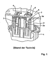
- FIG. 1 the prior art is shown as it is made for electrically contacting a throttle with a circuit board.
- the housing of the throttle is designated 1.
- the contact pin 3 In the housing of the throttle sits with the designated bearing bush 2, which receives the contact pin 3 longitudinally displaceable.
- the contact pin 3 has a collar 3a which is seated in a corresponding groove 2a of the socket 2.
- the generally designated 5 board shows the Stauerfspichen 6, each of which serves to receive the screw 7, which is screwed into the frontal internal thread of the pin 3, and insofar makes the contact between the Stauerfchtchen 6 on the one hand and the contact pin 3 on the other.
- the electrical connection of the contact pin 3 with the winding of the throttle is not shown.
- the internal thread of the pin 3 must be flush with the hole in the Stönfspichen 6, the connection between the housing 1 of the winding material and the board done. If the two parts, so the socket of the housing and the support legs with the hole for the screw on the board, not aligned with each other, so a connection can not be made. Rather, it must then be reworked to allow such a connection in the end, or the screw is clamped against the board.
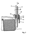
- the bearing bushing designated 2 is formed on the housing 1 such that it has an upper opening 10 from which the pin 3 exits.
- the end having a collar 13, wherein the collar 13 engages in the groove 3 a of the pin 3. It is essential here that the collar 13 is smaller in height than the length of the groove 3 a, so that the pin is movable axially in the direction of the double arrow 20.
- a plurality of centering fingers 15 are arranged, which due to their inherent elasticity keep the pin 3 centrally approximately centrally, as can be seen in FIG FIG. 2 results.
- the individual fingers 15 have a distance X to the side wall of the bearing bush 2, wherein the distance X finally defines the angle at which the pin 10 can be pivoted in accordance with the double arrow 25. Since the retaining arms 12 are formed resiliently, and can also move laterally, a corresponding to the edge of the socket with the distance X distance Y is provided, so that also the mobility of the pin 3 is given.
- centering fingers 15 serve only the better centering.
- the actual floating bearing is provided by the support arms 12 in the bearing bush. That is, the centering fingers 15 align the pin 3 perpendicular to the top of the socket so that it enters the corresponding opening in the board.
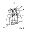
- the contact of the pin 3 on the board 5 is effected by the spring ring 40.
- the pin 3 which is held at the lower end by the bearing bush 2, protrudes in the upper region in the spring ring 40 and projects beyond this with its tip.
- the spring ring 40 consists of individual spring tongues 41, which are arranged in a circle on the board around the pin 3 around and are formed conically tapered to each other.
- the spring tongues are connected to the printed conductors of the board.
- the spring tongues 41 have end projections 41 a, with which the spring tongues 41 on the inner wall of the cylindrical Housing 45 ( FIG. 3b ) abut resiliently when protruding into the spring ring of the pen. This means that the spring tongues 41 are pressed against the spring force to the outside during the passage of the pin 3 by the spring ring, so that a secure electrical contact of the pin is given by the spring ring 40 to the board 5.
Landscapes
- Coupling Device And Connection With Printed Circuit (AREA)
Description
- Die vorliegende Erfindung betrifft eine elektrische Verbindung zwischen einem in einem Gehäuse angeordneten Wickelgut und Leiterbahnen einer Platine, die die Merkmalen des Oberbegriffs des Patentanspruchs 1 aufweist.
- Insbesondere Wechselrichter weisen häufig eine Mehrzahl an Drosseln auf, die in elektrischer Verbindung mit jeweils einer Platine stehen. Die Drosseln sind hierbei in Gehäusen, insbesondere topfartigen Gehäusen, untergebracht, wobei die topfartigen Gehäuse Kontaktstifte aufweisen, die mit der Drosselwicklung in Verbindung stehen. Wie bereits ausgeführt, besitzen Wechselrichter häufig mehrere Drosseln. Bekannt ist nun, die Drosseln des Wechselrichters in das Gehäuse des Wechselrichters einzubauen, alsdann die Platine einzubauen und die beiden Teile dann miteinander zu verschrauben. Die Verschraubung erfolgt im Einzelnen dadurch, dass an dem Gehäuse des Wickelgutes mehrere Buchsen vorgesehen sind, die Stifte aufnehmen, wobei die Stifte in den Buchsen in Längsrichtung beweglich angeordnet sind. Diese Stifte weisen ein Innengewinde auf. Auf der Platine selbst sind Stützfüßchen angeordnet, die mit den entsprechenden Leiterbahnen auf der Platine in Verbindung stehen. Diese Stützfüßchen besitzen auf ihrer Oberseite eine Bohrung zur Aufnahme einer Schraube, um mithilfe einer solchen Schraube die Kontaktstifte mit den Stützfüßchen zu verbinden. Das heißt, die Stifte werden gegen die Platine verschraubt. Eine solche Drossel besitzt üblicherweise vier Kontaktstifte zur Verbindung mit der Platine.
- Wie bereits an anderer Stelle ausgeführt, besitzt ein Wechselrichter üblicherweise mehrere Drosseln, die mit der Platine verbunden werden müssen. Um nun sicherzustellen, dass die Kontaktstifte mit den Stützfüßchen auf der Platine fluchten, ist eine extrem genaue Fertigung und Montage notwendig, da andernfalls eine Kontaktierung nicht möglich ist, wenn es nicht zu Schäden, insbesondere an der Platine, kommen soll.
- Aus der
US 5,055,055 A ist eine elektrische Verbindung für die Übertragung großer Ströme bekannt. Dabei weist eine Lagerbuchse eine Bohrung auf, in die eine in einem Zentralbereich mehrfach längs geschlitzte und dort in ihrem Radius eingezogene Federbuchse eingepresst ist. Diese Federbuchse greift mit ihrem Bereich geringsten Innendurchmessers an einem zylindrischen Abschnitt eines Kontaktstifts an, der so innerhalb der Bohrung der Lagerbuchse unter elastischer Verformung der Federbuchse um deren Taille herum verschwenkbar gelagert ist. - Aus der
US 5,334,035 A ist ein elektrischer Stecker zur Ausbildung einer vielpoligen elektrischen Verbindung bekannt, bei dem jedes Kontaktelement für einen Kontaktstift eine Buchse zur Aufnahme des Kontaktstiftes aufweist, die in Grenzen um einen axial nach hinten versetzten Punkt verschwenkbar ist, um sich auf die Längsachse des Kontaktstifts ausrichten zu können. - Aus der
US 5,482,470 A ist eine vielpolige elektrische Verbindung zwischen einem Stecker und einer Steckdose bekannt, bei der Kontaktstifte zwar in axialem Abstand zu einem Kontaktbereich in radialer Richtung starr abgestützt sind, aber noch vor dem Kontaktbereich gegenüber dem so gebildeten Haltepunkt in radialer Richtung elastisch ausgelenkt werden können, um sich auf sie aufnehmende Kontaktelemente ausrichten zu können. - Die der Erfindung zugrunde liegende Aufgabe besteht darin, bei einer elektrischen Verbindung der eingangs genannten Art einen Toleranzausgleich derart vorzusehen, dass auch bei nicht fluchtender Anordnung der zu kontaktierenden Teile eine Montage problemlos möglich ist.
- Zur Lösung der Aufgabe wird erfindungsgemäß eine elektrische Verbindung mit den Merkmalen des Patentanspruchs 1 vorgeschlagen.
- Der der Erfindung zugrunde liegende Gedanke besteht demzufolge darin, durch eine schwimmende Lagerung, was bedeutet, dass der Stift seitlich beweglich ist, dafür zu sorgen, dass bei entsprechenden Fertigungsungenauigkeiten der Stift dennoch mit dem Kontaktelement der Platine in Verbindung gebracht werden kann. Dies wird durch eine sogenannte "schwimmende" Lagerung" erreicht, bei der der Stift um einen gewissen Betrag durch die Lagerung verschwenkbar, also seitlich beweglich aufnehmbar ist.
- Vorteilhafte Merkmale und weitere Ausführungsformen sind den Unteransprüchen zu entnehmen.
- So ist nach einer Ausführungsform vorgesehen, dass die Lagerbuchse mehrere radial auf dem Umfang des Stiftes angreifende, elastisch nachgiebige Haltearme aufweist, wobei der Stift gegen die Haltearme seitlich beweglich in der Lagerbuchse gehalten ist. Wesentlich hierbei ist, dass die Lagerbuchse ein radiales Spiel aufweist, um zu gewährleisten, dass die elastisch nachgiebigen Haltearme tatsächlich seitlich ausweichen können, wenn es zu einer Verschwenkung des Stiftes in der Lagerbuchse kommt.
- Nach einer Ausführungsform ist hierbei vorgesehen, dass der Stift auf dem Umfang eine tangential umlaufende Nut aufweist, in die die Haltearme eingreifen. Hierbei ist insbesondere vorgesehen, dass die Haltearme jeweils endseitig einen Bund aufweisen, der in die Nut des Stiftes eingreift. Insbesondere dann, wenn die Nut in dem Stift eine axiale Erstreckung hat, die größer ist, als der Bund des jeweiligen Haltearms, ist eine Verschiebung des Stiftes parallel zu seiner Längsachse möglich. Das heißt, dass hierbei durch ein Verschwenken des Stiftes nicht nur ein Toleranzausgleich in radialer Richtung möglich ist, sondern vielmehr auch in axialer Richtung des Stiftes.
- Zur weiteren Zentrierung des Kontaktstiftes in der Lagerbuchse sind oberhalb der Haltearme in der Lagerbuchse Zentrierfinger vorgesehen. Mehrere solcher umfangsverteilt um den Stift herumgruppierte Zentrierfinger sorgen zusätzlich für eine Zentrierung des Stiftes im Wesentlichen senkrecht zur Oberseite der Lagerbuchse.
- Wie bereits an anderer Stelle erläutert, steht jeder Stift einerseits mit dem Wickelgut, und andererseits mit der Platine durch ein Kontaktelement in elektrischer Verbindung. Die Ausbildung eines solchen Kontaktelementes ist nach einem Merkmal der Erfindung vorteilhaft derart getroffen, dass das Kontaktelement als Federkranz ausgebildet ist. Ein solcher Federkranz umfasst vorteilhaft mehrere kreisförmig angeordnete Federzungen, die den Stift endseitig kontaktieren. Die Federzunge selbst ist hierbei unmittelbar an der Platine befestigt, wobei vorteilhaft nach einer Ausführungsform vorgesehen ist, dass die Federzungen in einem zylindrischen Gehäuse auf der Platine angeordnet sind. Bei eingeführtem Stift befinden sich die Federzungen radial an der Innenwandung des Gehäuses, d. h., die Federzungen stützen sich endseitig federnd an der Gehäuseinnenwand ab, was dazu führt, dass der Stift in gutem elektrischen Kontakt mit den Federzungen steht. Durch einen solchen strammen Sitz der Federzungen an dem Stift wird im Übrigen auch ein stabiler Sitz des Stiftes in dem durch die Federzungen gebildeten Kontaktelement in Verbindung mit den die Federzungen umgebenden Gehäuse bewirkt.
- Nach dem Stand der Technik war es so, dass zur elektrischen Verbindung des Kontaktstiftes mit der Platine die sogenannten "Stützfüßchen" vorgesehen sind, die mittels Schrauben mit dem Stift verbindbar sind. Eine solche Schraubverbindung setzt voraus, dass die Schraube mit ihrem Schraubenkopf von außen zugänglich ist. Das heißt, mit einer Kontaktierung der erfindungsgemäßen Art sind auch Montagen von Drosseln an Platinen an für Schraubenzieher oder Werkzeug allgemein unzugänglichen Stellen möglich, da die Stifte lediglich in den Federkranz eingeschoben werden müssen. Die erfindungsgemäße Kontaktierung ist darüber hinaus relativ schnell durchzuführen, da es sich hierbei um eine werkzeuglose Kontaktierung handelt. Des Weiteren ist die Kontaktierung überaus stabil, ohne die Platine zu belasten, da einerseits durch die schwimmende Lagerung des Stiftes und andererseits durch die Kontaktierung des Stiftes durch den Federkranz Erschütterungen weitestgehend abgefangen werden können, ohne dass sich diese auf die Platine übertragen. Die Kontaktierungen können sich auch nicht lösen, sodass auch aus diesem Grunde eine solche elektrische Verbindung überaus sicher ist. Weiterhin besteht nicht die Gefahr, bei der Montage eine Schraubverbindung zu vergessen, da - wie bereits ausgeführt - der elektrische Kontakt unmittelbar bereits dann hergestellt ist, wenn die Drossel mit ihrem Gehäuse in den Wechselrichter eingebaut ist. Es entfällt somit die gesonderte Kontaktierung der Stifte mit den Kontaktfüßchen, wie dies beschrieben wurde. Insofern wird hierdurch auch die Montagesicherheit erhöht.
- Gegenstand der Erfindung ist auch ein Wechselrichter, aufweisend mindestens ein elektrisches Wickelgut und mindestens eine Platine mit einer elektrischen Verbindung zwischen Wickelgut und Platine gemäß einem oder mehreren der zuvor abgehandelten Merkmale.
- Anhand der Zeichnungen wird die Erfindung nachstehend beispielhaft näher erläutert.
- Fig.1
- zeigt die Art der Verbindung nach dem Stand der Technik;
- Fig. 2
- zeigt die erfindungsgemäß Lagerung des Kontaktstiftes in der Lagerbuchse in einer Seitenansicht im Schnitt;
- Fig. 3a
- zeigt die Ausbildung des Federkranzes zur Kontaktierung des Kontaktstiftes auf der Platine;
- Fig. 3b
- zeigt den Federkranz in dem zylindrischen Gehäuse im Schnitt;
- Fig. 4
- zeigt schematisch das Wickelgut im mit der Platine verbundenen Zustand.
- Gemäß
Figur 1 ist der Stand der Technik dargestellt, wie er zur elektrischen Kontaktierung einer Drossel mit einer Platine vorgenommen wird. Das Gehäuse der Drossel ist mit 1 bezeichnet. In dem Gehäuse der Drossel sitzt die mit 2 bezeichnete Lagerbuchse ein, die den Kontaktstift 3 längs verschieblich aufnimmt. Hierzu weist der Kontaktstift 3 einen Bund 3a auf, der in einer entsprechenden Nut 2a der Buchse 2 einsitzt. Die insgesamt mit 5 bezeichnete Platine zeigt die Stützfüßchen 6, die jeweils der Aufnahme der Schraube 7 dient, die in das stirnseitige Innengewinde des Stiftes 3 eindrehbar ist, und insofern die Kontaktierung zwischen dem Stützfüßchen 6 einerseits und dem Kontaktstift 3 andererseits vornimmt. Die elektrische Verbindung des Kontaktstiftes 3 mit der Wicklung der Drossel ist nicht dargestellt. - Erkennbar ist, dass das Innengewinde des Stiftes 3 fluchtend mit der Bohrung in dem Stützfüßchen 6 liegen muss, soll die Verbindung zwischen dem Gehäuse 1 des Wickelgutes und der Platine erfolgen. Liegen die beiden Teile, also die Buchse des Gehäuses und das Stützfüßchen mit der Bohrung für die Schraube auf der Platine, nicht fluchtend zueinander, so kann eine Verbindung nicht erfolgen. Es muss dann vielmehr nachgearbeitet werden, um eine solche Verbindung schlussendlich zu ermöglichen, oder aber die Schraube wird gegen die Platine verspannt. Bei der Darstellung einer ersten Ausführungsform einer schwimmenden Lagerung gemäß
Figur 2 ist die mit 2 bezeichnete Lagerbuchse an dem Gehäuse 1 derart ausgebildet, dass diese eine obere Öffnung 10 aufweist, aus der der Stift 3 austritt. In der Lagerbuchse 2 bzw. in der Öffnung 10 der Lagerbuchse sind Haltearme 12 angeordnet, die endseitig einen Bund 13 aufweisen, wobei der Bund 13 in die Nut 3a des Stiftes 3 eingreift. Wesentlich hierbei ist, dass der Bund 13 in der Höhe von seinen Abmessungen her geringer ist, als die Länge der Nut 3a, sodass der Stift axial in Richtung des Doppelpfeils 20 beweglich ist. - Des Weiteren sind am oberen Ende der Öffnung 10 der Lagerbuchse 2 umfangsverteilt kreisförmig mehrere Zentrierfinger 15 angeordnet, die aufgrund ihrer Eigenelastizität den Stift 3 zentrisch etwa mittig halten, wie sich dies in Anschauung von
Figur 2 ergibt. Die einzelnen Finger 15 besitzen einen Abstand X zur Seitenwand der Lagerbuchse 2, wobei der Abstand X schlussendlich definiert, mit welchem Winkel der Stift 10 entsprechend dem Doppelpfeil 25 verschwenkbar ist. Da auch die Haltearme 12 federnd nachgiebig ausgebildet sind, und auch seitlich ausweichen können, ist ein zum Rand der Buchse mit dem Abstand X korrespondierender Abstand Y vorgesehen, sodass auch hierdurch die Beweglichkeit des Stiftes 3 gegeben ist. - Es sei an dieser Stelle darauf hingewiesen, dass die Zentrierfinger 15 lediglich der besseren Zentrierung dienen. Die eigentliche schwimmende Lagerung wird durch die Haltearme 12 in der Lagerbuchse bereitgestellt. Das heißt, die Zentrierfinger 15 richten den Stift 3 senkrecht zur Oberseite der Buchse aus, sodass er in die entsprechende Öffnung in der Platine einläuft.
- Die Kontaktierung des Stiftes 3 auf der Platine 5 erfolgt durch den Federkranz 40. Der Stift 3, der am unteren Ende durch die Lagerbuchse 2 gehalten ist, ragt im oberen Bereich in den Federkranz 40 hinein und überragt diesen mit seiner Spitze. Der Federkranz 40 besteht aus einzelnen Federzungen 41, die kreisförmig auf der Platine um den Stift 3 herum angeordnet sind und konisch aufeinander zulaufend ausgebildet sind. Die Federzungen stehen mit den Leiterbahnen der Platine in Verbindung. Die Federzungen 41 besitzen endseitig jeweils Vorsprünge 41a, mit denen die Federzungen 41 an der Innenwandung des zylindrischen Gehäuses 45 (
Figur 3b ) federnd anliegen, wenn in den Federkranz der Stift hineinragt. Das heißt, dass beim Durchtritt des Stiftes 3 durch den Federkranz die Federzungen 41 entgegen ihrer Federkraft nach aussen gedrückt werden, so daß eine sichere elektrische Kontaktierung des Stiftes durch den Federkranz 40 mit der Platine 5 gegeben ist.
Claims (14)
- Elektrische Verbindung zwischen einem in einem Gehäuse (1) angeordneten Wickelgut und Leitbahnen einer Platine (5), umfassend mehrere Kontaktstifte (3), die an dem Gehäuse (1) angeordnet sind, wobei jeder Kontaktstift (3) einerseits mit dem Wickelgut und andererseits durch ein Kontaktelement (40) mit der Platine (5) in elektrischer Verbindung steht, wobei für jeden Kontaktstift (3) eine Lagerbuchse (2, 30) an dem Gehäuse (1) vorgesehen ist, die den Kontaktstift schwimmend hält, dadurch gekennzeichnet, dass die Lagerbuchse (2, 30) mehrere radial an dem Umfang des Kontaktstiftes (3) angreifende, elastisch nachgiebige Haltearme (12) aufweist, wobei der Kontaktstift (3) gegen die Haltearme (12) seitlich beweglich durch die Lagerbuchse (2) gehalten ist, und dass oberhalb der Haltearme (12) in der Lagerbuchse (2) mehrere elastisch nachgiebige Zentrierfinger (15) umfangsverteilt um den Kontaktstift (3) herum angeordnet sind.
- Elektrische Verbindung nach Anspruch 1, dadurch gekennzeichnet, dass der Kontaktstift (3) schwenkbar durch die Lagerbuchse (2, 30) gehalten ist.
- Elektrische Verbindung nach einem der voranstehenden Ansprüche, dadurch gekennzeichnet, dass der Kontaktstift (3) parallel zur Längsachse des Kontaktstiftes (3) verschieblich durch die Lagerbuchse (2, 30) gehalten ist.
- Elektrische Verbindung nach einem der voranstehenden Ansprüche, dadurch gekennzeichnet, dass die Zentrierfinger (15) den Kontaktstift (3) senkrecht zur Oberseite der Lagebuchse (2) ausrichten.
- Elektrische Verbindung nach einem der voranstehenden Ansprüche, dadurch gekennzeichnet, dass der Kontaktstift (3) auf dem Umfang eine Nut (3a) aufweist, in die die Haltearme (12) eingreifen.
- Elektrische Verbindung nach Anspruch 5, dadurch gekennzeichnet, dass die Haltearme (12) jeweils endseitig einen Bund (12a) aufweisen, der in die Nut (3a) des Kontaktstiftes (3) eingreift.
- Elektrische Verbindung nach Anspruch 6, dadurch gekennzeichnet, dass die axiale Erstreckung der Nut (3a) grösser ist, als die Höhe des Bundes (12a) des jeweiligen Haltearms (12), um die axiale Beweglichkeit des Kontaktstiftes (3) in der Lagerbuchse (2) zu gewährleisten.
- Elektrische Verbindung zwischen dem Gehäuse (1) eines Wickelgutes und einer Platine (5) nach einem der voranstehenden Ansprüche, dadurch gekennzeichnet, dass das Kontaktelement als Federkranz (40) ausgebildet ist.
- Elektrische Verbindung zwischen dem Gehäuse (1) eines Wickelgutes und einer Platine (5) nach Anspruch 8, dadurch gekennzeichnet, dass der Federkranz (40) mehrere kreisförmig angeordnete Federzungen (41) umfasst, die den Kontaktstift (3) endseitig kontaktieren.
- Elektrische Verbindung zwischen dem Gehäuse (1) eines Wickelgutes und einer Platine (5) nach Anspruch 9, dadurch gekennzeichnet, dass die Federzungen (41) an der Platine (5) befestigt sind.
- Elektrische Verbindung zwischen dem Gehäuse (1) eines Wickelgutes und einer Platine (5) nach Anspruch 9, dadurch gekennzeichnet, dass die Federzungen (41) in elektrischer Verbindung mit einer Leiterbahn der Platine (5) stehen.
- Elektrische Verbindung zwischen dem Gehäuse (1) eines Wickelgutes und einer Platine (5) nach Anspruch 9, dadurch gekennzeichnet, dass die Federzungen (41) in einem zylindrischen Gehäuse (45) auf der Platine (5) angeordnet sind.
- Elektrische Verbindung zwischen dem Gehäuse (1) eines Wickelgutes und einer Platine (5) nach Anspruch 12, dadurch gekennzeichnet, dass sich die Federzungen (41) radial an der Innenwandung des Gehäuses (45) im eingeführten Zustand des Kontaktstiftes (3) abstutzen.
- Wechselrichter aufweisend mindestens ein elektrisches Wickelgut und mindestens eine Platine (5) mit einer elektrischen Verbindung zwischen Wickelgut und Platine (5) gemäß einem oder mehreren der Ansprüche 1 bis 13.
Priority Applications (2)
| Application Number | Priority Date | Filing Date | Title |
|---|---|---|---|
| EP20090011403 EP2293390B1 (de) | 2009-09-05 | 2009-09-05 | Elektrische Verbindung zwischen dem Gehäuse eines Wickelgutes und einer Platine |
| PCT/EP2010/062981 WO2011026950A1 (de) | 2009-09-05 | 2010-09-03 | Elektrische verbindung zwischen einem elektrischen wickelgut und leiterbahnen einer platine |
Applications Claiming Priority (1)
| Application Number | Priority Date | Filing Date | Title |
|---|---|---|---|
| EP20090011403 EP2293390B1 (de) | 2009-09-05 | 2009-09-05 | Elektrische Verbindung zwischen dem Gehäuse eines Wickelgutes und einer Platine |
Publications (2)
| Publication Number | Publication Date |
|---|---|
| EP2293390A1 EP2293390A1 (de) | 2011-03-09 |
| EP2293390B1 true EP2293390B1 (de) | 2013-01-16 |
Family
ID=41412436
Family Applications (1)
| Application Number | Title | Priority Date | Filing Date |
|---|---|---|---|
| EP20090011403 Active EP2293390B1 (de) | 2009-09-05 | 2009-09-05 | Elektrische Verbindung zwischen dem Gehäuse eines Wickelgutes und einer Platine |
Country Status (2)
| Country | Link |
|---|---|
| EP (1) | EP2293390B1 (de) |
| WO (1) | WO2011026950A1 (de) |
Families Citing this family (2)
| Publication number | Priority date | Publication date | Assignee | Title |
|---|---|---|---|---|
| DE102012102851B4 (de) * | 2012-04-02 | 2015-05-28 | Phoenix Contact Gmbh & Co. Kg | Flexible Wanddurchführung für ein elektrisches Signal |
| JP6759433B2 (ja) * | 2019-09-04 | 2020-09-23 | イリソ電子工業株式会社 | 端子及びコネクタ |
Family Cites Families (6)
| Publication number | Priority date | Publication date | Assignee | Title |
|---|---|---|---|---|
| US5055055A (en) * | 1990-10-12 | 1991-10-08 | Elcon Products International Company | Circuit board connector system |
| DE4118696C2 (de) * | 1991-06-07 | 1994-03-17 | Hirschmann Richard Gmbh Co | Steckverbinder |
| EP0625810B1 (de) * | 1993-05-20 | 1999-01-20 | Sumitomo Wiring Systems, Ltd. | Elektrischer Steckverbinder |
| US20020019168A1 (en) * | 1999-01-12 | 2002-02-14 | Robert W. Hooley | Pin array header with floating surface mount interconnects |
| US6431891B1 (en) * | 2000-12-26 | 2002-08-13 | Hon Hai Precision Ind. Co., Ltd. | Power connector with easily removable conductive pin |
| US6461174B1 (en) * | 2001-09-12 | 2002-10-08 | Hon Hai Precision Ind. Co., Ltd. | Power connector more easily and cheaply manufactured |
-
2009
- 2009-09-05 EP EP20090011403 patent/EP2293390B1/de active Active
-
2010
- 2010-09-03 WO PCT/EP2010/062981 patent/WO2011026950A1/de not_active Ceased
Also Published As
| Publication number | Publication date |
|---|---|
| EP2293390A1 (de) | 2011-03-09 |
| WO2011026950A1 (de) | 2011-03-10 |
Similar Documents
| Publication | Publication Date | Title |
|---|---|---|
| DE102010045042B4 (de) | Elektrische Steckverbindung insbesondere Rundsteckverbindung | |
| EP2912728B1 (de) | Kontaktvorrichtung | |
| EP1730815B1 (de) | Koaxialsteckverbindung für leiterplatten mit gefedertem toleranzausgleich | |
| EP1955413B1 (de) | Push-pull-koaxialsteckverbinder | |
| DE2822365C2 (de) | ||
| WO2014015944A1 (de) | Kontaktelement | |
| EP3014707B1 (de) | Steckverbindermodul | |
| EP3787128B1 (de) | Steckverbindung | |
| EP2973887B1 (de) | Steckverbinder | |
| EP1306933B1 (de) | Führungssystem für Kontaktstecker | |
| EP4356485A1 (de) | Berührschutzpin | |
| EP2293390B1 (de) | Elektrische Verbindung zwischen dem Gehäuse eines Wickelgutes und einer Platine | |
| DE69902947T2 (de) | Koaxiale kabelverbindungseinrichtung | |
| EP2192658B1 (de) | Verbindungseinrichtung | |
| DE19754527C2 (de) | Klinkenbuchse | |
| DE2606917C3 (de) | Elektrischer Koaxialsteckverbinder | |
| DE102015116284A1 (de) | Vorrichtung zur Kontaktierung von elektrisch leitenden Bauelementen | |
| AT16923U1 (de) | Einbausteckverbinder | |
| EP3074996B1 (de) | Trägermodul und trägergerüst für polungswiderstände eines stufenschalters, befestigungselement für polungswiderstände sowie anordnung von polungswiderständen eines stufenschalters | |
| DE1665931B2 (de) | Antennensteckdose mit koaxialer Steckbuchse | |
| DE102008028518B4 (de) | Elektrische Steckvorrichtung | |
| DE102008028516B4 (de) | Elektrische Steckvorrichtung | |
| DE19516240A1 (de) | Mehrzweck-Verbinderbefestigungsschraube | |
| EP2804267B1 (de) | Zugentlastung für Steckverbinder | |
| DE102022131107A1 (de) | Leiterplattendirektanschluss |
Legal Events
| Date | Code | Title | Description |
|---|---|---|---|
| PUAI | Public reference made under article 153(3) epc to a published international application that has entered the european phase |
Free format text: ORIGINAL CODE: 0009012 |
|
| AK | Designated contracting states |
Kind code of ref document: A1 Designated state(s): AT BE BG CH CY CZ DE DK EE ES FI FR GB GR HR HU IE IS IT LI LT LU LV MC MK MT NL NO PL PT RO SE SI SK SM TR |
|
| AX | Request for extension of the european patent |
Extension state: AL BA RS |
|
| RIN1 | Information on inventor provided before grant (corrected) |
Inventor name: GWADERA MARIUSZ Inventor name: GEBERT, BERND Inventor name: HOBEIN, THORSTEN Inventor name: WALCZAK |
|
| RIN1 | Information on inventor provided before grant (corrected) |
Inventor name: HOBEIN, THORSTEN Inventor name: WALCZAK, MARIUSZ Inventor name: GEBERT, BERND Inventor name: GWADERA, MARIUSZ |
|
| 17P | Request for examination filed |
Effective date: 20110820 |
|
| GRAP | Despatch of communication of intention to grant a patent |
Free format text: ORIGINAL CODE: EPIDOSNIGR1 |
|
| GRAJ | Information related to disapproval of communication of intention to grant by the applicant or resumption of examination proceedings by the epo deleted |
Free format text: ORIGINAL CODE: EPIDOSDIGR1 |
|
| GRAP | Despatch of communication of intention to grant a patent |
Free format text: ORIGINAL CODE: EPIDOSNIGR1 |
|
| GRAS | Grant fee paid |
Free format text: ORIGINAL CODE: EPIDOSNIGR3 |
|
| GRAA | (expected) grant |
Free format text: ORIGINAL CODE: 0009210 |
|
| AK | Designated contracting states |
Kind code of ref document: B1 Designated state(s): AT BE BG CH CY CZ DE DK EE ES FI FR GB GR HR HU IE IS IT LI LT LU LV MC MK MT NL NO PL PT RO SE SI SK SM TR |
|
| REG | Reference to a national code |
Ref country code: GB Ref legal event code: FG4D Free format text: NOT ENGLISH |
|
| REG | Reference to a national code |
Ref country code: CH Ref legal event code: EP |
|
| REG | Reference to a national code |
Ref country code: IE Ref legal event code: FG4D Free format text: LANGUAGE OF EP DOCUMENT: GERMAN |
|
| REG | Reference to a national code |
Ref country code: AT Ref legal event code: REF Ref document number: 594333 Country of ref document: AT Kind code of ref document: T Effective date: 20130215 Ref country code: CH Ref legal event code: EP |
|
| REG | Reference to a national code |
Ref country code: DE Ref legal event code: R096 Ref document number: 502009006028 Country of ref document: DE Effective date: 20130314 |
|
| REG | Reference to a national code |
Ref country code: NL Ref legal event code: VDEP Effective date: 20130116 |
|
| REG | Reference to a national code |
Ref country code: LT Ref legal event code: MG4D |
|
| PG25 | Lapsed in a contracting state [announced via postgrant information from national office to epo] |
Ref country code: ES Free format text: LAPSE BECAUSE OF FAILURE TO SUBMIT A TRANSLATION OF THE DESCRIPTION OR TO PAY THE FEE WITHIN THE PRESCRIBED TIME-LIMIT Effective date: 20130427 Ref country code: IS Free format text: LAPSE BECAUSE OF FAILURE TO SUBMIT A TRANSLATION OF THE DESCRIPTION OR TO PAY THE FEE WITHIN THE PRESCRIBED TIME-LIMIT Effective date: 20130516 Ref country code: BG Free format text: LAPSE BECAUSE OF FAILURE TO SUBMIT A TRANSLATION OF THE DESCRIPTION OR TO PAY THE FEE WITHIN THE PRESCRIBED TIME-LIMIT Effective date: 20130416 Ref country code: SE Free format text: LAPSE BECAUSE OF FAILURE TO SUBMIT A TRANSLATION OF THE DESCRIPTION OR TO PAY THE FEE WITHIN THE PRESCRIBED TIME-LIMIT Effective date: 20130116 Ref country code: LT Free format text: LAPSE BECAUSE OF FAILURE TO SUBMIT A TRANSLATION OF THE DESCRIPTION OR TO PAY THE FEE WITHIN THE PRESCRIBED TIME-LIMIT Effective date: 20130116 Ref country code: NO Free format text: LAPSE BECAUSE OF FAILURE TO SUBMIT A TRANSLATION OF THE DESCRIPTION OR TO PAY THE FEE WITHIN THE PRESCRIBED TIME-LIMIT Effective date: 20130416 |
|
| PG25 | Lapsed in a contracting state [announced via postgrant information from national office to epo] |
Ref country code: NL Free format text: LAPSE BECAUSE OF FAILURE TO SUBMIT A TRANSLATION OF THE DESCRIPTION OR TO PAY THE FEE WITHIN THE PRESCRIBED TIME-LIMIT Effective date: 20130116 Ref country code: SI Free format text: LAPSE BECAUSE OF FAILURE TO SUBMIT A TRANSLATION OF THE DESCRIPTION OR TO PAY THE FEE WITHIN THE PRESCRIBED TIME-LIMIT Effective date: 20130116 Ref country code: LV Free format text: LAPSE BECAUSE OF FAILURE TO SUBMIT A TRANSLATION OF THE DESCRIPTION OR TO PAY THE FEE WITHIN THE PRESCRIBED TIME-LIMIT Effective date: 20130116 Ref country code: PT Free format text: LAPSE BECAUSE OF FAILURE TO SUBMIT A TRANSLATION OF THE DESCRIPTION OR TO PAY THE FEE WITHIN THE PRESCRIBED TIME-LIMIT Effective date: 20130516 Ref country code: FI Free format text: LAPSE BECAUSE OF FAILURE TO SUBMIT A TRANSLATION OF THE DESCRIPTION OR TO PAY THE FEE WITHIN THE PRESCRIBED TIME-LIMIT Effective date: 20130116 Ref country code: PL Free format text: LAPSE BECAUSE OF FAILURE TO SUBMIT A TRANSLATION OF THE DESCRIPTION OR TO PAY THE FEE WITHIN THE PRESCRIBED TIME-LIMIT Effective date: 20130116 Ref country code: GR Free format text: LAPSE BECAUSE OF FAILURE TO SUBMIT A TRANSLATION OF THE DESCRIPTION OR TO PAY THE FEE WITHIN THE PRESCRIBED TIME-LIMIT Effective date: 20130417 |
|
| PG25 | Lapsed in a contracting state [announced via postgrant information from national office to epo] |
Ref country code: HR Free format text: LAPSE BECAUSE OF FAILURE TO SUBMIT A TRANSLATION OF THE DESCRIPTION OR TO PAY THE FEE WITHIN THE PRESCRIBED TIME-LIMIT Effective date: 20130116 |
|
| PG25 | Lapsed in a contracting state [announced via postgrant information from national office to epo] |
Ref country code: SK Free format text: LAPSE BECAUSE OF FAILURE TO SUBMIT A TRANSLATION OF THE DESCRIPTION OR TO PAY THE FEE WITHIN THE PRESCRIBED TIME-LIMIT Effective date: 20130116 Ref country code: DK Free format text: LAPSE BECAUSE OF FAILURE TO SUBMIT A TRANSLATION OF THE DESCRIPTION OR TO PAY THE FEE WITHIN THE PRESCRIBED TIME-LIMIT Effective date: 20130116 Ref country code: CZ Free format text: LAPSE BECAUSE OF FAILURE TO SUBMIT A TRANSLATION OF THE DESCRIPTION OR TO PAY THE FEE WITHIN THE PRESCRIBED TIME-LIMIT Effective date: 20130116 Ref country code: EE Free format text: LAPSE BECAUSE OF FAILURE TO SUBMIT A TRANSLATION OF THE DESCRIPTION OR TO PAY THE FEE WITHIN THE PRESCRIBED TIME-LIMIT Effective date: 20130116 Ref country code: RO Free format text: LAPSE BECAUSE OF FAILURE TO SUBMIT A TRANSLATION OF THE DESCRIPTION OR TO PAY THE FEE WITHIN THE PRESCRIBED TIME-LIMIT Effective date: 20130116 |
|
| PLBE | No opposition filed within time limit |
Free format text: ORIGINAL CODE: 0009261 |
|
| STAA | Information on the status of an ep patent application or granted ep patent |
Free format text: STATUS: NO OPPOSITION FILED WITHIN TIME LIMIT |
|
| PG25 | Lapsed in a contracting state [announced via postgrant information from national office to epo] |
Ref country code: CY Free format text: LAPSE BECAUSE OF FAILURE TO SUBMIT A TRANSLATION OF THE DESCRIPTION OR TO PAY THE FEE WITHIN THE PRESCRIBED TIME-LIMIT Effective date: 20130116 |
|
| 26N | No opposition filed |
Effective date: 20131017 |
|
| PG25 | Lapsed in a contracting state [announced via postgrant information from national office to epo] |
Ref country code: IT Free format text: LAPSE BECAUSE OF FAILURE TO SUBMIT A TRANSLATION OF THE DESCRIPTION OR TO PAY THE FEE WITHIN THE PRESCRIBED TIME-LIMIT Effective date: 20130116 |
|
| REG | Reference to a national code |
Ref country code: DE Ref legal event code: R097 Ref document number: 502009006028 Country of ref document: DE Effective date: 20131017 |
|
| BERE | Be: lapsed |
Owner name: SMA SOLAR TECHNOLOGY A.G. Effective date: 20130930 |
|
| PG25 | Lapsed in a contracting state [announced via postgrant information from national office to epo] |
Ref country code: MC Free format text: LAPSE BECAUSE OF FAILURE TO SUBMIT A TRANSLATION OF THE DESCRIPTION OR TO PAY THE FEE WITHIN THE PRESCRIBED TIME-LIMIT Effective date: 20130116 |
|
| REG | Reference to a national code |
Ref country code: CH Ref legal event code: PL |
|
| GBPC | Gb: european patent ceased through non-payment of renewal fee |
Effective date: 20130905 |
|
| REG | Reference to a national code |
Ref country code: FR Ref legal event code: ST Effective date: 20140530 |
|
| REG | Reference to a national code |
Ref country code: IE Ref legal event code: MM4A |
|
| PG25 | Lapsed in a contracting state [announced via postgrant information from national office to epo] |
Ref country code: IE Free format text: LAPSE BECAUSE OF NON-PAYMENT OF DUE FEES Effective date: 20130905 Ref country code: LI Free format text: LAPSE BECAUSE OF NON-PAYMENT OF DUE FEES Effective date: 20130930 Ref country code: BE Free format text: LAPSE BECAUSE OF NON-PAYMENT OF DUE FEES Effective date: 20130930 Ref country code: GB Free format text: LAPSE BECAUSE OF NON-PAYMENT OF DUE FEES Effective date: 20130905 Ref country code: CH Free format text: LAPSE BECAUSE OF NON-PAYMENT OF DUE FEES Effective date: 20130930 |
|
| PG25 | Lapsed in a contracting state [announced via postgrant information from national office to epo] |
Ref country code: FR Free format text: LAPSE BECAUSE OF NON-PAYMENT OF DUE FEES Effective date: 20130930 |
|
| PG25 | Lapsed in a contracting state [announced via postgrant information from national office to epo] |
Ref country code: SM Free format text: LAPSE BECAUSE OF FAILURE TO SUBMIT A TRANSLATION OF THE DESCRIPTION OR TO PAY THE FEE WITHIN THE PRESCRIBED TIME-LIMIT Effective date: 20130116 |
|
| PG25 | Lapsed in a contracting state [announced via postgrant information from national office to epo] |
Ref country code: TR Free format text: LAPSE BECAUSE OF FAILURE TO SUBMIT A TRANSLATION OF THE DESCRIPTION OR TO PAY THE FEE WITHIN THE PRESCRIBED TIME-LIMIT Effective date: 20130116 Ref country code: MT Free format text: LAPSE BECAUSE OF FAILURE TO SUBMIT A TRANSLATION OF THE DESCRIPTION OR TO PAY THE FEE WITHIN THE PRESCRIBED TIME-LIMIT Effective date: 20130116 |
|
| PG25 | Lapsed in a contracting state [announced via postgrant information from national office to epo] |
Ref country code: LU Free format text: LAPSE BECAUSE OF NON-PAYMENT OF DUE FEES Effective date: 20130905 Ref country code: HU Free format text: LAPSE BECAUSE OF FAILURE TO SUBMIT A TRANSLATION OF THE DESCRIPTION OR TO PAY THE FEE WITHIN THE PRESCRIBED TIME-LIMIT; INVALID AB INITIO Effective date: 20090905 Ref country code: MK Free format text: LAPSE BECAUSE OF FAILURE TO SUBMIT A TRANSLATION OF THE DESCRIPTION OR TO PAY THE FEE WITHIN THE PRESCRIBED TIME-LIMIT Effective date: 20130116 |
|
| REG | Reference to a national code |
Ref country code: AT Ref legal event code: MM01 Ref document number: 594333 Country of ref document: AT Kind code of ref document: T Effective date: 20140905 |
|
| PG25 | Lapsed in a contracting state [announced via postgrant information from national office to epo] |
Ref country code: AT Free format text: LAPSE BECAUSE OF NON-PAYMENT OF DUE FEES Effective date: 20140905 |
|
| PGFP | Annual fee paid to national office [announced via postgrant information from national office to epo] |
Ref country code: DE Payment date: 20240919 Year of fee payment: 16 |