EP2293390B1 - Connexion électrique entre le boîtier d'un matériau d'enroulement et une platine - Google Patents
Connexion électrique entre le boîtier d'un matériau d'enroulement et une platine Download PDFInfo
- Publication number
- EP2293390B1 EP2293390B1 EP20090011403 EP09011403A EP2293390B1 EP 2293390 B1 EP2293390 B1 EP 2293390B1 EP 20090011403 EP20090011403 EP 20090011403 EP 09011403 A EP09011403 A EP 09011403A EP 2293390 B1 EP2293390 B1 EP 2293390B1
- Authority
- EP
- European Patent Office
- Prior art keywords
- electrical connection
- housing
- contact pin
- circuit board
- contact
- Prior art date
- Legal status (The legal status is an assumption and is not a legal conclusion. Google has not performed a legal analysis and makes no representation as to the accuracy of the status listed.)
- Active
Links
- 238000004804 winding Methods 0.000 title description 10
- 210000002105 tongue Anatomy 0.000 claims description 19
- 239000004020 conductor Substances 0.000 claims description 4
- 239000000463 material Substances 0.000 description 7
- 230000015572 biosynthetic process Effects 0.000 description 2
- 238000004519 manufacturing process Methods 0.000 description 2
- 230000005405 multipole Effects 0.000 description 2
- BASFCYQUMIYNBI-UHFFFAOYSA-N platinum Chemical compound [Pt] BASFCYQUMIYNBI-UHFFFAOYSA-N 0.000 description 2
- 230000000712 assembly Effects 0.000 description 1
- 238000000429 assembly Methods 0.000 description 1
- 230000005540 biological transmission Effects 0.000 description 1
- 230000001419 dependent effect Effects 0.000 description 1
- 238000006073 displacement reaction Methods 0.000 description 1
- 230000005489 elastic deformation Effects 0.000 description 1
- 230000035939 shock Effects 0.000 description 1
Images


Classifications
-
- H—ELECTRICITY
- H01—ELECTRIC ELEMENTS
- H01R—ELECTRICALLY-CONDUCTIVE CONNECTIONS; STRUCTURAL ASSOCIATIONS OF A PLURALITY OF MUTUALLY-INSULATED ELECTRICAL CONNECTING ELEMENTS; COUPLING DEVICES; CURRENT COLLECTORS
- H01R13/00—Details of coupling devices of the kinds covered by groups H01R12/70 or H01R24/00 - H01R33/00
- H01R13/62—Means for facilitating engagement or disengagement of coupling parts or for holding them in engagement
- H01R13/629—Additional means for facilitating engagement or disengagement of coupling parts, e.g. aligning or guiding means, levers, gas pressure electrical locking indicators, manufacturing tolerances
- H01R13/631—Additional means for facilitating engagement or disengagement of coupling parts, e.g. aligning or guiding means, levers, gas pressure electrical locking indicators, manufacturing tolerances for engagement only
- H01R13/6315—Additional means for facilitating engagement or disengagement of coupling parts, e.g. aligning or guiding means, levers, gas pressure electrical locking indicators, manufacturing tolerances for engagement only allowing relative movement between coupling parts, e.g. floating connection
-
- H—ELECTRICITY
- H01—ELECTRIC ELEMENTS
- H01R—ELECTRICALLY-CONDUCTIVE CONNECTIONS; STRUCTURAL ASSOCIATIONS OF A PLURALITY OF MUTUALLY-INSULATED ELECTRICAL CONNECTING ELEMENTS; COUPLING DEVICES; CURRENT COLLECTORS
- H01R13/00—Details of coupling devices of the kinds covered by groups H01R12/70 or H01R24/00 - H01R33/00
- H01R13/02—Contact members
- H01R13/04—Pins or blades for co-operation with sockets
- H01R13/08—Resiliently-mounted rigid pins or blades
Definitions
- the present invention relates to an electrical connection between a winding material arranged in a housing and printed conductors of a printed circuit board, which has the features of the preamble of patent claim 1.
- inverters often have a plurality of chokes, which are in electrical connection with a respective circuit board.
- the throttles are in this case housed in housings, in particular pot-like housings, the pot-like housings having contact pins which are connected to the inductor winding.
- inverters often have several reactors. It is now known to install the reactors of the inverter in the housing of the inverter, then install the board and then screw the two parts together. The screwing is done in detail by the fact that a plurality of sockets are provided on the housing of the winding material, record the pins, wherein the pins are arranged to be movable in the bushes in the longitudinal direction. These pins have an internal thread.
- Stützfozochen are arranged, which are in communication with the corresponding tracks on the board.
- These support feet have on their top a bore for receiving a screw to connect by means of such a screw, the contact pins with the support feet. That is, the pins are screwed against the board.
- Such a choke usually has four pins for connection to the board.
- an inverter usually has multiple chokes that must be connected to the board. To now ensure that the Contact pins are aligned with the support feet on the board, an extremely accurate production and assembly is necessary, otherwise a contact is not possible, if it should not come to damage, especially on the board.
- a bearing bush has a bore into which a longitudinally slotted in a central region longitudinally and there retracted in its radius spring bush is pressed.
- This spring bushing engages with its smallest inner diameter portion of a cylindrical portion of a contact pin, which is so mounted within the bore of the bearing bush under elastic deformation of the spring bushing around the waist pivotally.
- each contact element for a contact pin has a socket for receiving the contact pin, which is pivotable about an axially offset to the rear point in order to align with the longitudinal axis of the contact pin can ,
- the object underlying the invention is to provide a tolerance compensation in an electrical connection of the type mentioned in such a way that even with not aligned arrangement of the parts to be contacted mounting is easily possible.
- the idea underlying the invention is therefore, by a floating bearing, which means that the pin is laterally movable, to ensure that with appropriate manufacturing inaccuracies of the pin can still be brought into contact with the contact element of the board.
- This is achieved by a so-called “floating” storage ", in which the pin by a certain amount by the bearing pivotally, that is laterally movably receivable.
- the bearing bush has a plurality of resiliently engaging retaining arms acting radially on the circumference of the pin, wherein the pin is held laterally movably in the bearing bush against the retaining arms. It is essential here that the bearing bush has a radial play, in order to ensure that the elastically yielding retaining arms can actually deflect laterally when pivoting of the pin occurs in the bearing bush.
- the pin on the circumference has a tangential circumferential groove, in which engage the retaining arms.
- the holding arms are provided to each have a collar at the end, which engages in the groove of the pin.
- the groove in the pin has an axial extent which is greater than the collar of the respective holding arm, a displacement of the pin parallel to its longitudinal axis is possible. This means that not only a tolerance compensation in the radial direction is possible by pivoting the pin, but also in the axial direction of the pin.
- centering fingers are provided above the support arms in the bearing bush. Several such circumferentially distributed around the pin grouped centering fingers additionally ensure centering of the pin substantially perpendicular to the top of the bearing bush.
- each pin is on the one hand with the winding material, and on the other hand with the board by a contact element in electrical connection.
- the formation of such a contact element is advantageously made according to a feature of the invention such that the contact element is designed as a spring wreath.
- Such a spring ring advantageously comprises a plurality of circularly arranged spring tongues, which contact the pin end.
- the spring tongue itself is in this case attached directly to the board, wherein it is advantageously provided according to an embodiment that the spring tongues are arranged in a cylindrical housing on the board. When inserted pin, the spring tongues are radially on the inner wall of the housing, d.
- the spring tongues are supported at the end resiliently on the housing inner wall, resulting in that the pin is in good electrical contact with the spring tongues.
- the contact is extremely stable without burdening the board, as on the one hand by the floating bearing of the pin and on the other hand by the contact of the pin through the spring ring shocks can be largely intercepted, without being transmitted to the board.
- the contacts can not solve either, so that for this reason such an electrical connection is extremely safe.
- there is no risk to forget a screw during assembly since - as already stated - the electrical contact is already made directly when the throttle is installed with its housing in the inverter. It thus eliminates the separate contact of the pins with the Kunststofffzipchen, as has been described. In this respect, this also increases the mounting security.
- the invention also provides an inverter, comprising at least one electrical winding material and at least one circuit board with an electrical connection between the winding material and the circuit board according to one or more of the previously discussed features.
- FIG. 1 the prior art is shown as it is made for electrically contacting a throttle with a circuit board.
- the housing of the throttle is designated 1.
- the contact pin 3 In the housing of the throttle sits with the designated bearing bush 2, which receives the contact pin 3 longitudinally displaceable.
- the contact pin 3 has a collar 3a which is seated in a corresponding groove 2a of the socket 2.
- the generally designated 5 board shows the Stauerfspichen 6, each of which serves to receive the screw 7, which is screwed into the frontal internal thread of the pin 3, and insofar makes the contact between the Stauerfchtchen 6 on the one hand and the contact pin 3 on the other.
- the electrical connection of the contact pin 3 with the winding of the throttle is not shown.
- the internal thread of the pin 3 must be flush with the hole in the Stönfspichen 6, the connection between the housing 1 of the winding material and the board done. If the two parts, so the socket of the housing and the support legs with the hole for the screw on the board, not aligned with each other, so a connection can not be made. Rather, it must then be reworked to allow such a connection in the end, or the screw is clamped against the board.
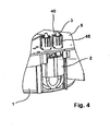
- the bearing bushing designated 2 is formed on the housing 1 such that it has an upper opening 10 from which the pin 3 exits.
- the end having a collar 13, wherein the collar 13 engages in the groove 3 a of the pin 3. It is essential here that the collar 13 is smaller in height than the length of the groove 3 a, so that the pin is movable axially in the direction of the double arrow 20.
- a plurality of centering fingers 15 are arranged, which due to their inherent elasticity keep the pin 3 centrally approximately centrally, as can be seen in FIG FIG. 2 results.
- the individual fingers 15 have a distance X to the side wall of the bearing bush 2, wherein the distance X finally defines the angle at which the pin 10 can be pivoted in accordance with the double arrow 25. Since the retaining arms 12 are formed resiliently, and can also move laterally, a corresponding to the edge of the socket with the distance X distance Y is provided, so that also the mobility of the pin 3 is given.
- centering fingers 15 serve only the better centering.
- the actual floating bearing is provided by the support arms 12 in the bearing bush. That is, the centering fingers 15 align the pin 3 perpendicular to the top of the socket so that it enters the corresponding opening in the board.
- the contact of the pin 3 on the board 5 is effected by the spring ring 40.
- the pin 3 which is held at the lower end by the bearing bush 2, protrudes in the upper region in the spring ring 40 and projects beyond this with its tip.
- the spring ring 40 consists of individual spring tongues 41, which are arranged in a circle on the board around the pin 3 around and are formed conically tapered to each other.
- the spring tongues are connected to the printed conductors of the board.
- the spring tongues 41 have end projections 41 a, with which the spring tongues 41 on the inner wall of the cylindrical Housing 45 ( FIG. 3b ) abut resiliently when protruding into the spring ring of the pen. This means that the spring tongues 41 are pressed against the spring force to the outside during the passage of the pin 3 by the spring ring, so that a secure electrical contact of the pin is given by the spring ring 40 to the board 5.
Landscapes
- Coupling Device And Connection With Printed Circuit (AREA)
Claims (14)
- Connexion électrique entre un élément à enroulement et des pistes conductrices d'une platine (5), comprenant plusieurs broches de contact (3), disposées sur le boîtier (1), chaque broche de contact (3) étant reliée d'une part à l'élément à enroulement et d'autre part à la platine (5) par l'intermédiaire d'un élément de contact (40), une douille de palier (2, 30) étant prévue sur le boîtier (1) pour chaque broche de contact (3), qui maintient la broche de contact de manière flottante, caractérisée en ce que la douille de palier (2, 30) comprend plusieurs bras de maintien (12) élastiques se trouvant à la périphérie de la broche de contact (3), la broche de contact (3) étant maintenue de manière mobile latéralement contre les bras de maintien (12) par la douille de palier (2) et en ce que, au-dessus des bras de maintien (12), dans la douille de palier (2) se trouvent plusieurs doigts de centrage (15) élastiques répartis sur la périphérie de la broche de contact (3).
- Connexion électrique selon la revendication 1, caractérisée en ce que la broche de contact (3) est maintenue de manière pivotante par la douille de palier (2, 30).
- Connexion électrique selon l'une des revendications précédentes, caractérisée en ce que la broche de contact (3) est maintenue de manière mobile parallèlement à l'axe longitudinal de la broche de contact (3) par la douille de palier (2, 30).
- Connexion électrique selon l'une des revendications précédentes, caractérisée en ce que les doigts de centrage (15) orientent la broche de contact (3) perpendiculairement par rapport au côté supérieur de la douille de palier (2).
- Connexion électrique selon l'une des revendications précédentes, caractérisée en ce que la broche de contact (3) comprend une rainure (3a) dans laquelle s'emboîtent les bras de maintien (12).
- Connexion électrique selon la revendication 5, caractérisée en ce que les bras de maintien (12) comprennent chacun à leur extrémité un collet (12a) qui s'emboîte dans la rainure (3a) de la broche de contact (3).
- Connexion électrique selon la revendication 6, caractérisée en ce que l'extension axiale de la rainure (3a) est supérieure à la hauteur du collet (12a) du bras de maintien (12) correspondant, afin de garantir la mobilité axiale de la broche de contact (3) dans la douille de palier (2).
- Connexion électrique entre le boîtier (1) d'un élément à enroulement et une platine (5) selon l'une des revendications précédentes, caractérisée en ce que l'élément de contact est conçu comme une couronne élastique (40).
- Connexion électrique entre le boîtier (1) d'un élément à enroulement et une platine (5) selon la revendication 8, caractérisée en ce que la couronne élastique (40) comprend plusieurs lames élastiques (41) disposées en cercle qui entrent en contact avec la broche de contact (3).
- Connexion électrique entre le boîtier (1) d'un élément à enroulement et une platine (5) selon la revendication 9, caractérisée en ce que les lames élastiques (41) sont fixées à la platine (5).
- Connexion électrique entre le boîtier (1) d'un élément à enroulement et une platine (5) selon la revendication 9, caractérisée en ce que les lames élastiques (41) sont connectées électriquement à une piste conductrice de la platine (5).
- Connexion électrique entre le boîtier (1) d'un élément à enroulement et une platine (5) selon la revendication 9, caractérisée en ce que les lames élastiques (41) sont disposées dans un boîtier cylindrique (45) sur la platine (5).
- Connexion électrique entre le boîtier (1) d'un élément à enroulement et une platine (5) selon la revendication 12, caractérisée en ce que les lames élastiques (41) s'appuient radialement contre la paroi interne du boîtier (45) dans un état rentré de la broche de contact (3).
- Onduleur comprenant au moins un élément à enroulement électrique et au moins une platine (5) avec une connexion électrique entre l'élément à enroulement et la platine (5) selon une ou plusieurs des revendications 1 à 13.
Priority Applications (2)
| Application Number | Priority Date | Filing Date | Title |
|---|---|---|---|
| EP20090011403 EP2293390B1 (fr) | 2009-09-05 | 2009-09-05 | Connexion électrique entre le boîtier d'un matériau d'enroulement et une platine |
| PCT/EP2010/062981 WO2011026950A1 (fr) | 2009-09-05 | 2010-09-03 | Connexion électrique entre une matière à enrouler électrique et les pistes conductrices d'une carte |
Applications Claiming Priority (1)
| Application Number | Priority Date | Filing Date | Title |
|---|---|---|---|
| EP20090011403 EP2293390B1 (fr) | 2009-09-05 | 2009-09-05 | Connexion électrique entre le boîtier d'un matériau d'enroulement et une platine |
Publications (2)
| Publication Number | Publication Date |
|---|---|
| EP2293390A1 EP2293390A1 (fr) | 2011-03-09 |
| EP2293390B1 true EP2293390B1 (fr) | 2013-01-16 |
Family
ID=41412436
Family Applications (1)
| Application Number | Title | Priority Date | Filing Date |
|---|---|---|---|
| EP20090011403 Active EP2293390B1 (fr) | 2009-09-05 | 2009-09-05 | Connexion électrique entre le boîtier d'un matériau d'enroulement et une platine |
Country Status (2)
| Country | Link |
|---|---|
| EP (1) | EP2293390B1 (fr) |
| WO (1) | WO2011026950A1 (fr) |
Families Citing this family (2)
| Publication number | Priority date | Publication date | Assignee | Title |
|---|---|---|---|---|
| DE102012102851B4 (de) * | 2012-04-02 | 2015-05-28 | Phoenix Contact Gmbh & Co. Kg | Flexible Wanddurchführung für ein elektrisches Signal |
| JP6759433B2 (ja) * | 2019-09-04 | 2020-09-23 | イリソ電子工業株式会社 | 端子及びコネクタ |
Family Cites Families (6)
| Publication number | Priority date | Publication date | Assignee | Title |
|---|---|---|---|---|
| US5055055A (en) * | 1990-10-12 | 1991-10-08 | Elcon Products International Company | Circuit board connector system |
| DE4118696C2 (de) * | 1991-06-07 | 1994-03-17 | Hirschmann Richard Gmbh Co | Steckverbinder |
| EP0625810B1 (fr) * | 1993-05-20 | 1999-01-20 | Sumitomo Wiring Systems, Ltd. | Connecteur électrique |
| US20020019168A1 (en) * | 1999-01-12 | 2002-02-14 | Robert W. Hooley | Pin array header with floating surface mount interconnects |
| US6431891B1 (en) * | 2000-12-26 | 2002-08-13 | Hon Hai Precision Ind. Co., Ltd. | Power connector with easily removable conductive pin |
| US6461174B1 (en) * | 2001-09-12 | 2002-10-08 | Hon Hai Precision Ind. Co., Ltd. | Power connector more easily and cheaply manufactured |
-
2009
- 2009-09-05 EP EP20090011403 patent/EP2293390B1/fr active Active
-
2010
- 2010-09-03 WO PCT/EP2010/062981 patent/WO2011026950A1/fr not_active Ceased
Also Published As
| Publication number | Publication date |
|---|---|
| EP2293390A1 (fr) | 2011-03-09 |
| WO2011026950A1 (fr) | 2011-03-10 |
Similar Documents
| Publication | Publication Date | Title |
|---|---|---|
| DE102010045042B4 (de) | Elektrische Steckverbindung insbesondere Rundsteckverbindung | |
| EP2912728B1 (fr) | Dispositif de contact | |
| EP1730815B1 (fr) | Fiche de raccordement coaxiale pour cartes a circuits imprimes, munie d'une compensation de tolerance par ressort | |
| EP1955413B1 (fr) | Connecteur coaxial push-pull | |
| DE2822365C2 (fr) | ||
| WO2014015944A1 (fr) | Élément de contact | |
| EP3014707B1 (fr) | Module de connecteur enfichable | |
| EP3787128B1 (fr) | Connecteur enfichable | |
| EP2973887B1 (fr) | Connecteur | |
| EP1306933B1 (fr) | Système de guidage pour fiche de contact | |
| EP4356485A1 (fr) | Capuchon de protection | |
| EP2293390B1 (fr) | Connexion électrique entre le boîtier d'un matériau d'enroulement et une platine | |
| DE69902947T2 (de) | Koaxiale kabelverbindungseinrichtung | |
| EP2192658B1 (fr) | Dispositif de raccordement | |
| DE19754527C2 (de) | Klinkenbuchse | |
| DE2606917C3 (de) | Elektrischer Koaxialsteckverbinder | |
| DE102015116284A1 (de) | Vorrichtung zur Kontaktierung von elektrisch leitenden Bauelementen | |
| AT16923U1 (de) | Einbausteckverbinder | |
| EP3074996B1 (fr) | Module de support et ossature de support pour résistances de polarité d'un commutateur à plots, élément de fixation pour résistances de polarité et ensemble de résistances de polarité d'un commutateur à plots | |
| DE1665931B2 (de) | Antennensteckdose mit koaxialer Steckbuchse | |
| DE102008028518B4 (de) | Elektrische Steckvorrichtung | |
| DE102008028516B4 (de) | Elektrische Steckvorrichtung | |
| DE19516240A1 (de) | Mehrzweck-Verbinderbefestigungsschraube | |
| EP2804267B1 (fr) | Décharge de traction pour connecteur à fiches | |
| DE102022131107A1 (de) | Leiterplattendirektanschluss |
Legal Events
| Date | Code | Title | Description |
|---|---|---|---|
| PUAI | Public reference made under article 153(3) epc to a published international application that has entered the european phase |
Free format text: ORIGINAL CODE: 0009012 |
|
| AK | Designated contracting states |
Kind code of ref document: A1 Designated state(s): AT BE BG CH CY CZ DE DK EE ES FI FR GB GR HR HU IE IS IT LI LT LU LV MC MK MT NL NO PL PT RO SE SI SK SM TR |
|
| AX | Request for extension of the european patent |
Extension state: AL BA RS |
|
| RIN1 | Information on inventor provided before grant (corrected) |
Inventor name: GWADERA MARIUSZ Inventor name: GEBERT, BERND Inventor name: HOBEIN, THORSTEN Inventor name: WALCZAK |
|
| RIN1 | Information on inventor provided before grant (corrected) |
Inventor name: HOBEIN, THORSTEN Inventor name: WALCZAK, MARIUSZ Inventor name: GEBERT, BERND Inventor name: GWADERA, MARIUSZ |
|
| 17P | Request for examination filed |
Effective date: 20110820 |
|
| GRAP | Despatch of communication of intention to grant a patent |
Free format text: ORIGINAL CODE: EPIDOSNIGR1 |
|
| GRAJ | Information related to disapproval of communication of intention to grant by the applicant or resumption of examination proceedings by the epo deleted |
Free format text: ORIGINAL CODE: EPIDOSDIGR1 |
|
| GRAP | Despatch of communication of intention to grant a patent |
Free format text: ORIGINAL CODE: EPIDOSNIGR1 |
|
| GRAS | Grant fee paid |
Free format text: ORIGINAL CODE: EPIDOSNIGR3 |
|
| GRAA | (expected) grant |
Free format text: ORIGINAL CODE: 0009210 |
|
| AK | Designated contracting states |
Kind code of ref document: B1 Designated state(s): AT BE BG CH CY CZ DE DK EE ES FI FR GB GR HR HU IE IS IT LI LT LU LV MC MK MT NL NO PL PT RO SE SI SK SM TR |
|
| REG | Reference to a national code |
Ref country code: GB Ref legal event code: FG4D Free format text: NOT ENGLISH |
|
| REG | Reference to a national code |
Ref country code: CH Ref legal event code: EP |
|
| REG | Reference to a national code |
Ref country code: IE Ref legal event code: FG4D Free format text: LANGUAGE OF EP DOCUMENT: GERMAN |
|
| REG | Reference to a national code |
Ref country code: AT Ref legal event code: REF Ref document number: 594333 Country of ref document: AT Kind code of ref document: T Effective date: 20130215 Ref country code: CH Ref legal event code: EP |
|
| REG | Reference to a national code |
Ref country code: DE Ref legal event code: R096 Ref document number: 502009006028 Country of ref document: DE Effective date: 20130314 |
|
| REG | Reference to a national code |
Ref country code: NL Ref legal event code: VDEP Effective date: 20130116 |
|
| REG | Reference to a national code |
Ref country code: LT Ref legal event code: MG4D |
|
| PG25 | Lapsed in a contracting state [announced via postgrant information from national office to epo] |
Ref country code: ES Free format text: LAPSE BECAUSE OF FAILURE TO SUBMIT A TRANSLATION OF THE DESCRIPTION OR TO PAY THE FEE WITHIN THE PRESCRIBED TIME-LIMIT Effective date: 20130427 Ref country code: IS Free format text: LAPSE BECAUSE OF FAILURE TO SUBMIT A TRANSLATION OF THE DESCRIPTION OR TO PAY THE FEE WITHIN THE PRESCRIBED TIME-LIMIT Effective date: 20130516 Ref country code: BG Free format text: LAPSE BECAUSE OF FAILURE TO SUBMIT A TRANSLATION OF THE DESCRIPTION OR TO PAY THE FEE WITHIN THE PRESCRIBED TIME-LIMIT Effective date: 20130416 Ref country code: SE Free format text: LAPSE BECAUSE OF FAILURE TO SUBMIT A TRANSLATION OF THE DESCRIPTION OR TO PAY THE FEE WITHIN THE PRESCRIBED TIME-LIMIT Effective date: 20130116 Ref country code: LT Free format text: LAPSE BECAUSE OF FAILURE TO SUBMIT A TRANSLATION OF THE DESCRIPTION OR TO PAY THE FEE WITHIN THE PRESCRIBED TIME-LIMIT Effective date: 20130116 Ref country code: NO Free format text: LAPSE BECAUSE OF FAILURE TO SUBMIT A TRANSLATION OF THE DESCRIPTION OR TO PAY THE FEE WITHIN THE PRESCRIBED TIME-LIMIT Effective date: 20130416 |
|
| PG25 | Lapsed in a contracting state [announced via postgrant information from national office to epo] |
Ref country code: NL Free format text: LAPSE BECAUSE OF FAILURE TO SUBMIT A TRANSLATION OF THE DESCRIPTION OR TO PAY THE FEE WITHIN THE PRESCRIBED TIME-LIMIT Effective date: 20130116 Ref country code: SI Free format text: LAPSE BECAUSE OF FAILURE TO SUBMIT A TRANSLATION OF THE DESCRIPTION OR TO PAY THE FEE WITHIN THE PRESCRIBED TIME-LIMIT Effective date: 20130116 Ref country code: LV Free format text: LAPSE BECAUSE OF FAILURE TO SUBMIT A TRANSLATION OF THE DESCRIPTION OR TO PAY THE FEE WITHIN THE PRESCRIBED TIME-LIMIT Effective date: 20130116 Ref country code: PT Free format text: LAPSE BECAUSE OF FAILURE TO SUBMIT A TRANSLATION OF THE DESCRIPTION OR TO PAY THE FEE WITHIN THE PRESCRIBED TIME-LIMIT Effective date: 20130516 Ref country code: FI Free format text: LAPSE BECAUSE OF FAILURE TO SUBMIT A TRANSLATION OF THE DESCRIPTION OR TO PAY THE FEE WITHIN THE PRESCRIBED TIME-LIMIT Effective date: 20130116 Ref country code: PL Free format text: LAPSE BECAUSE OF FAILURE TO SUBMIT A TRANSLATION OF THE DESCRIPTION OR TO PAY THE FEE WITHIN THE PRESCRIBED TIME-LIMIT Effective date: 20130116 Ref country code: GR Free format text: LAPSE BECAUSE OF FAILURE TO SUBMIT A TRANSLATION OF THE DESCRIPTION OR TO PAY THE FEE WITHIN THE PRESCRIBED TIME-LIMIT Effective date: 20130417 |
|
| PG25 | Lapsed in a contracting state [announced via postgrant information from national office to epo] |
Ref country code: HR Free format text: LAPSE BECAUSE OF FAILURE TO SUBMIT A TRANSLATION OF THE DESCRIPTION OR TO PAY THE FEE WITHIN THE PRESCRIBED TIME-LIMIT Effective date: 20130116 |
|
| PG25 | Lapsed in a contracting state [announced via postgrant information from national office to epo] |
Ref country code: SK Free format text: LAPSE BECAUSE OF FAILURE TO SUBMIT A TRANSLATION OF THE DESCRIPTION OR TO PAY THE FEE WITHIN THE PRESCRIBED TIME-LIMIT Effective date: 20130116 Ref country code: DK Free format text: LAPSE BECAUSE OF FAILURE TO SUBMIT A TRANSLATION OF THE DESCRIPTION OR TO PAY THE FEE WITHIN THE PRESCRIBED TIME-LIMIT Effective date: 20130116 Ref country code: CZ Free format text: LAPSE BECAUSE OF FAILURE TO SUBMIT A TRANSLATION OF THE DESCRIPTION OR TO PAY THE FEE WITHIN THE PRESCRIBED TIME-LIMIT Effective date: 20130116 Ref country code: EE Free format text: LAPSE BECAUSE OF FAILURE TO SUBMIT A TRANSLATION OF THE DESCRIPTION OR TO PAY THE FEE WITHIN THE PRESCRIBED TIME-LIMIT Effective date: 20130116 Ref country code: RO Free format text: LAPSE BECAUSE OF FAILURE TO SUBMIT A TRANSLATION OF THE DESCRIPTION OR TO PAY THE FEE WITHIN THE PRESCRIBED TIME-LIMIT Effective date: 20130116 |
|
| PLBE | No opposition filed within time limit |
Free format text: ORIGINAL CODE: 0009261 |
|
| STAA | Information on the status of an ep patent application or granted ep patent |
Free format text: STATUS: NO OPPOSITION FILED WITHIN TIME LIMIT |
|
| PG25 | Lapsed in a contracting state [announced via postgrant information from national office to epo] |
Ref country code: CY Free format text: LAPSE BECAUSE OF FAILURE TO SUBMIT A TRANSLATION OF THE DESCRIPTION OR TO PAY THE FEE WITHIN THE PRESCRIBED TIME-LIMIT Effective date: 20130116 |
|
| 26N | No opposition filed |
Effective date: 20131017 |
|
| PG25 | Lapsed in a contracting state [announced via postgrant information from national office to epo] |
Ref country code: IT Free format text: LAPSE BECAUSE OF FAILURE TO SUBMIT A TRANSLATION OF THE DESCRIPTION OR TO PAY THE FEE WITHIN THE PRESCRIBED TIME-LIMIT Effective date: 20130116 |
|
| REG | Reference to a national code |
Ref country code: DE Ref legal event code: R097 Ref document number: 502009006028 Country of ref document: DE Effective date: 20131017 |
|
| BERE | Be: lapsed |
Owner name: SMA SOLAR TECHNOLOGY A.G. Effective date: 20130930 |
|
| PG25 | Lapsed in a contracting state [announced via postgrant information from national office to epo] |
Ref country code: MC Free format text: LAPSE BECAUSE OF FAILURE TO SUBMIT A TRANSLATION OF THE DESCRIPTION OR TO PAY THE FEE WITHIN THE PRESCRIBED TIME-LIMIT Effective date: 20130116 |
|
| REG | Reference to a national code |
Ref country code: CH Ref legal event code: PL |
|
| GBPC | Gb: european patent ceased through non-payment of renewal fee |
Effective date: 20130905 |
|
| REG | Reference to a national code |
Ref country code: FR Ref legal event code: ST Effective date: 20140530 |
|
| REG | Reference to a national code |
Ref country code: IE Ref legal event code: MM4A |
|
| PG25 | Lapsed in a contracting state [announced via postgrant information from national office to epo] |
Ref country code: IE Free format text: LAPSE BECAUSE OF NON-PAYMENT OF DUE FEES Effective date: 20130905 Ref country code: LI Free format text: LAPSE BECAUSE OF NON-PAYMENT OF DUE FEES Effective date: 20130930 Ref country code: BE Free format text: LAPSE BECAUSE OF NON-PAYMENT OF DUE FEES Effective date: 20130930 Ref country code: GB Free format text: LAPSE BECAUSE OF NON-PAYMENT OF DUE FEES Effective date: 20130905 Ref country code: CH Free format text: LAPSE BECAUSE OF NON-PAYMENT OF DUE FEES Effective date: 20130930 |
|
| PG25 | Lapsed in a contracting state [announced via postgrant information from national office to epo] |
Ref country code: FR Free format text: LAPSE BECAUSE OF NON-PAYMENT OF DUE FEES Effective date: 20130930 |
|
| PG25 | Lapsed in a contracting state [announced via postgrant information from national office to epo] |
Ref country code: SM Free format text: LAPSE BECAUSE OF FAILURE TO SUBMIT A TRANSLATION OF THE DESCRIPTION OR TO PAY THE FEE WITHIN THE PRESCRIBED TIME-LIMIT Effective date: 20130116 |
|
| PG25 | Lapsed in a contracting state [announced via postgrant information from national office to epo] |
Ref country code: TR Free format text: LAPSE BECAUSE OF FAILURE TO SUBMIT A TRANSLATION OF THE DESCRIPTION OR TO PAY THE FEE WITHIN THE PRESCRIBED TIME-LIMIT Effective date: 20130116 Ref country code: MT Free format text: LAPSE BECAUSE OF FAILURE TO SUBMIT A TRANSLATION OF THE DESCRIPTION OR TO PAY THE FEE WITHIN THE PRESCRIBED TIME-LIMIT Effective date: 20130116 |
|
| PG25 | Lapsed in a contracting state [announced via postgrant information from national office to epo] |
Ref country code: LU Free format text: LAPSE BECAUSE OF NON-PAYMENT OF DUE FEES Effective date: 20130905 Ref country code: HU Free format text: LAPSE BECAUSE OF FAILURE TO SUBMIT A TRANSLATION OF THE DESCRIPTION OR TO PAY THE FEE WITHIN THE PRESCRIBED TIME-LIMIT; INVALID AB INITIO Effective date: 20090905 Ref country code: MK Free format text: LAPSE BECAUSE OF FAILURE TO SUBMIT A TRANSLATION OF THE DESCRIPTION OR TO PAY THE FEE WITHIN THE PRESCRIBED TIME-LIMIT Effective date: 20130116 |
|
| REG | Reference to a national code |
Ref country code: AT Ref legal event code: MM01 Ref document number: 594333 Country of ref document: AT Kind code of ref document: T Effective date: 20140905 |
|
| PG25 | Lapsed in a contracting state [announced via postgrant information from national office to epo] |
Ref country code: AT Free format text: LAPSE BECAUSE OF NON-PAYMENT OF DUE FEES Effective date: 20140905 |
|
| PGFP | Annual fee paid to national office [announced via postgrant information from national office to epo] |
Ref country code: DE Payment date: 20240919 Year of fee payment: 16 |