EP2293410A2 - Dispositif de commande d'énergie pour un réseau d'énergie avec une unité de commande pour commander un flux d'énergie entre l'unité de production d'énergie, l'unité de stockage d'énergie, l'unité de chargement et/ou le réseau d'énergie - Google Patents
Dispositif de commande d'énergie pour un réseau d'énergie avec une unité de commande pour commander un flux d'énergie entre l'unité de production d'énergie, l'unité de stockage d'énergie, l'unité de chargement et/ou le réseau d'énergie Download PDFInfo
- Publication number
- EP2293410A2 EP2293410A2 EP10175112A EP10175112A EP2293410A2 EP 2293410 A2 EP2293410 A2 EP 2293410A2 EP 10175112 A EP10175112 A EP 10175112A EP 10175112 A EP10175112 A EP 10175112A EP 2293410 A2 EP2293410 A2 EP 2293410A2
- Authority
- EP
- European Patent Office
- Prior art keywords
- energy
- unit
- power
- control device
- load
- Prior art date
- Legal status (The legal status is an assumption and is not a legal conclusion. Google has not performed a legal analysis and makes no representation as to the accuracy of the status listed.)
- Granted
Links
Images




Classifications
-
- H—ELECTRICITY
- H02—GENERATION; CONVERSION OR DISTRIBUTION OF ELECTRIC POWER
- H02J—ELECTRIC POWER NETWORKS; CIRCUIT ARRANGEMENTS OR SYSTEMS FOR SUPPLYING OR DISTRIBUTING ELECTRIC POWER; SYSTEMS FOR STORING ELECTRIC ENERGY
- H02J3/00—Circuit arrangements for AC mains or AC distribution networks
- H02J3/38—Arrangements for feeding a single network from two or more generators or sources in parallel; Arrangements for feeding already energised networks from additional generators or sources in parallel
- H02J3/381—Dispersed generators
-
- H—ELECTRICITY
- H02—GENERATION; CONVERSION OR DISTRIBUTION OF ELECTRIC POWER
- H02J—ELECTRIC POWER NETWORKS; CIRCUIT ARRANGEMENTS OR SYSTEMS FOR SUPPLYING OR DISTRIBUTING ELECTRIC POWER; SYSTEMS FOR STORING ELECTRIC ENERGY
- H02J3/00—Circuit arrangements for AC mains or AC distribution networks
- H02J3/38—Arrangements for feeding a single network from two or more generators or sources in parallel; Arrangements for feeding already energised networks from additional generators or sources in parallel
- H02J3/46—Controlling the sharing of generated power between the generators, sources or networks
- H02J3/466—Scheduling or selectively controlling the operation of the generators or sources, e.g. connecting or disconnecting generators to meet a demand
-
- H—ELECTRICITY
- H02—GENERATION; CONVERSION OR DISTRIBUTION OF ELECTRIC POWER
- H02J—ELECTRIC POWER NETWORKS; CIRCUIT ARRANGEMENTS OR SYSTEMS FOR SUPPLYING OR DISTRIBUTING ELECTRIC POWER; SYSTEMS FOR STORING ELECTRIC ENERGY
- H02J2101/00—Supply or distribution of decentralised, dispersed or local electric power generation
- H02J2101/20—Dispersed power generation using renewable energy sources
- H02J2101/22—Solar energy
- H02J2101/24—Photovoltaics
-
- H—ELECTRICITY
- H02—GENERATION; CONVERSION OR DISTRIBUTION OF ELECTRIC POWER
- H02J—ELECTRIC POWER NETWORKS; CIRCUIT ARRANGEMENTS OR SYSTEMS FOR SUPPLYING OR DISTRIBUTING ELECTRIC POWER; SYSTEMS FOR STORING ELECTRIC ENERGY
- H02J7/00—Circuit arrangements for charging or discharging batteries or for supplying loads from batteries
- H02J7/34—Parallel operation in networks using both storage and other DC sources, e.g. providing buffering
- H02J7/35—Parallel operation in networks using both storage and other DC sources, e.g. providing buffering with light sensitive cells
-
- Y—GENERAL TAGGING OF NEW TECHNOLOGICAL DEVELOPMENTS; GENERAL TAGGING OF CROSS-SECTIONAL TECHNOLOGIES SPANNING OVER SEVERAL SECTIONS OF THE IPC; TECHNICAL SUBJECTS COVERED BY FORMER USPC CROSS-REFERENCE ART COLLECTIONS [XRACs] AND DIGESTS
- Y02—TECHNOLOGIES OR APPLICATIONS FOR MITIGATION OR ADAPTATION AGAINST CLIMATE CHANGE
- Y02E—REDUCTION OF GREENHOUSE GAS [GHG] EMISSIONS, RELATED TO ENERGY GENERATION, TRANSMISSION OR DISTRIBUTION
- Y02E10/00—Energy generation through renewable energy sources
- Y02E10/50—Photovoltaic [PV] energy
- Y02E10/56—Power conversion systems, e.g. maximum power point trackers
Definitions
- the present invention relates to a power control apparatus for a power grid and a method for controlling an operation of a power control apparatus.
- Such an energy control device provides a household as a load unit with power.
- a power generation unit such as a photovoltaic system, which generates energy from renewable resources, such as solar radiation, and makes it available to the household. If the photovoltaic system generates a lot of energy when the weather conditions are good, for example, the household is sufficiently supplied with electricity. If the photovoltaic generates less energy than the household consumes, eg at night or in bad weather conditions, it is necessary for the household to cover its energy needs from the (public) energy grid.
- the energy control device has a network connection unit, by means of which the energy control device can be connected to the power grid to remove this energy. Also, this connection allows the power management device to generate power to the power grid If the photovoltaic system generates more energy than is consumed by the household.
- Such an energy control device has the disadvantage that the exchange of energy between the energy control device and the power grid is expensive.
- each energy flow between the energy control device and the power grid has to be balanced, which i.a. involves complex calculation methods.
- DE 100 18 943 A1 describes a photovoltaic inverter in which all required for a photovoltaic island system energy sources and energy sinks are coupled via converters exclusively to a DC bus with freely selectable voltage level and a control or control of these components via the evaluation of the voltage level of the DC bus.
- a photovoltaic generator via a matching converter, a bidirectional charge controller with a battery and a stand-alone inverter with the Verbraucheir connected via a DC bus and connected a control and regulating device for energy management on the evaluation of the voltage level of the DC bus.
- a load management controller that distributes electrical energy from a power generation unit to a plurality of power consumption sub-circuits. Excessive, generated energy can be supplied to a storage circuit. If the energy demand of the sub-circuits exceeds the supply capacity of the power-generating unit, additional electricity is drawn from the public grid. For this purpose, current flow from the public grid and the power generation unit are brought together and introduced together in a main switchboard. This distributes the electrical energy to the consumption sub-circuits. Similar solutions are out GB 2455421 A and EP 1 848 085 A2 known.
- the object of the invention is to provide a power control device which avoids the above mentioned drawbacks.
- an energy control device for a power network comprising: a power generation unit, in particular a photovoltaic unit, for generating energy from renewable resources, an energy storage unit for storing energy, a measuring device for determining the energy consumption of a load unit (111) for consuming power, a power terminal unit, in particular an inverter unit, for connecting the power management device to a power grid, extracting power from the power grid and supplying power to the power grid, and a control unit for controlling power flow between the power generation unit, the power storage unit Load unit and / or the power grid.
- the control unit is designed to control the amount of energy that is fed into the power grid as a function of the amount of energy consumed by the load unit.
- an on-demand and optimized supply is realized, for example, by allowing the control unit to preferably control the energy flow between the energy control device and the power grid such that a first amount of energy that the load unit receives and consumes from the intrinsic power generation unit substantially second amount of the energy that the load unit receives from the power grid and consumes.
- Energy surpluses within the energy management device are stored in the energy storage unit at times when the power generation unit is under power Energy to the unit of burden also to balance the amounts of internally and externally provided energy.
- An advantage of the invention is on the one hand, that all consumers of the island grid are connected as a single load unit and consequently via a single consumption line to the control unit. There is therefore no differentiated connection of several load units to the control unit and no separate detection of consumption and corresponding allocation of certain types of energy to individual load units required.
- control unit regulates the fluctuating delivery quantities and purchase quantities according to the current.
- This makes it possible to selectively control the mixture of electricity taken from the public grid and electricity supplied from the energy-providing unit.
- a control frequency is achieved in which a control process in a few seconds or even several control operations per second and thereby significantly reduces the losses.
- the power generation unit is signal-coupled to the control unit in such a way that only the amount of energy required by the load unit is conducted by the power generation unit to an inverter and, in addition, generated energy is passed directly to the storage unit without passing through the inverter.
- a controllable, direct direct current connection between the power generation unit and the memory unit can be made via the control unit, in order to allow in this way a very low-loss transmission of energy.
- the energy control device makes it possible to feed only a regulated amount of energy via the inverter into the public grid and to supply another amount directly as direct current to the storage unit.
- both the power generation unit and the load unit, the storage unit and the public network are connected directly and without positive interposition of an AC or rectifier with the control unit.
- the control unit can thereby optimally regulate the flow of current between these units, gfs. from the power generation unit and for the load unit or supply the public network provided power of the inverter unit for subsequent supply as AC power to the consumers or the public network and gfs. Supply the current drawn from the public network to a rectifier in order to then supply it to the storage unit.
- the control unit is also able to supply power from the public network directly to the load unit and to supply power from the power generation unit directly to the storage unit, without a DC or an inverter being passed through.
- the storage unit may be provided as a central storage unit arranged in the area of the power generation unit or the control unit. In certain applications, however, the storage unit may also be part of a consumer of the load unit and may be designed in particular as a summed form of a plurality of such storage forms.
- the energy control device preferably allows a limitation of the feed-in power in the public network. This limitation can be achieved according to the invention by storing electrical power from the power generation unit, which exceeds the sum of the electrical power consumed by the load units and the maximum power to be fed into the public grid due to a feed limitation, in the memory unit. Furthermore, the energy control device according to the invention also enables a phase-related limitation of the feed-in power in a multiphase public grid, for example, by injecting such excess power or energy to those phases where a feed-in limit has not yet been reached, but to phases in which the feed-in limit already exists is reached, no further power is fed.
- the storage unit which operates in rapid loading and unloading cycles, and by rapid switching between the various power generating units (internally to the power control device and externally (i.e., in the power grid)) or even in a mixed operation of these power sources.
- the present invention allows a mixed, optimized use of the two energy sources, ie, the power controller-internal power generation unit and the power grid power generation unit.
- the power controller-internal power generation unit By means of a prediction unit losses due to arrival or expiration times of the load unit (or load units) can be detected and systemically compensated.
- a mixed operation of the island-internal and external power generation units eliminates restrictions on the use of loads.
- control unit is configured to cause an energy flow from the power generation unit to the energy storage unit when the energy generated exceeds the energy consumption of the load unit.
- control unit decides in dependence on the current (or even predicted) energy requirement of the load unit whether energy is to be supplied to the storage unit or to the energy grid. It is achieved that only in the case of an energy surplus energy is discharged from the power control device to the power grid. The expense of accounting can be reduced.
- control unit is configured to control a flow of energy from the power generating unit and / or from the power storage unit to the power grid in an amount that depends on the amount of power drawn from the power unit from the power grid, preferably corresponding to that amount.
- the energy storage unit always has energy reserves whenever possible in order to supply the load unit with energy.
- control unit may in particular be designed in such a way that by controlling the energy flows between power generation unit, storage unit, load unit and public network over a period of a few seconds, minutes, or one or more hours in amount matching withdrawal and feed from / in the public Net scored. In just such a way can be achieved that over such periods a constant relationship between withdrawal and feed is adjusted.
- a virtual balance envelope around a household with a power generation unit, e.g. a photovoltaic system, and a feed and removal connection to the public network is in this case neutral at all times.
- a power generation unit e.g. a photovoltaic system
- a feed and removal connection to the public network is in this case neutral at all times.
- the only one or several phases of a home network, the corresponding to a more multi-phase public network is formed is formed (for example, a single-phase inverter in a three-phase home network) increase the stability of the public network.
- the power from the power generation unit is directed to only one or several phases of the load units of the home network.
- the control device can then be designed, for example, in such a way that, in the event of an undersupply of one of the other phases (in the case of a three-phase power network that is one of the other two phases), this undersupply is compensated for by removal from the public network.
- electricity is fed into the public grid on the phase (s) supplied by the power generation unit, thereby ensuring that the flow of energy into the public grid corresponds to the amount of energy flowing from the public grid.
- the further development according to the invention is also advantageous when the current generated in the power generation unit is reversed by means of a polyphase inverter to all phases of a public network, for example by means of a three-phase inverter in a three-phase network.
- a polyphase inverter to all phases of a public network
- there are constant fluctuations in the power demand caused by the load units on the individual phases which lead to different loadings of the phases among one another.
- an overuse is compensated on a heavily stressed by the load units phase by removal from the public grid and fed at the same time on one or more other phases of electricity in the public network.
- an over-served phase of the public network can be relieved by single-phase withdrawal from this phase.
- an undersupplied phase of the public network can be supported by single-phase feeding to this phase from the power generation unit or the storage unit.
- control unit is configured to cause the flow of energy to the energy storage unit until the energy storage unit is fully charged or to a predetermined degree.
- the energy control device can always access the energy storage unit as an energy reserve to meet the needs of the load unit. An energy flow from the power grid to the energy control device according to the invention can be further reduced.
- the control unit preferably has a prediction unit for predetermining the energy flow to be controlled.
- An advantage of this preferred embodiment is that the energy flow can be determined as a function of factors that represent a customary and / or expected energy generation course and / or energy consumption course.
- the storage of energy and the supply of energy in the power grid can be precisely controlled according to the invention to ensure optimum supply to the load unit.
- the prediction unit is configured, the energy consumption of the load unit, in particular based on a reference period and / or time, Kirtag-, and / or season information, and / or the energy generated by the power generation unit, in particular based on weather information, reference data and / or Measurement data to predict.
- the energy generation process can be predetermined particularly precisely, as a result of which an energy flow can be planned accordingly and further reduced between energy network and energy control device.
- the energy storage unit (115) is connected to the energy generation unit (113) and the network connection unit (114) by means of a first capacitor unit and a second capacitor unit (155).
- this training achieves symmetrization and load reduction even in the case of asymmetrical loads.
- the first and second capacitor units may each have one or more capacitors.
- the operating conditions of the energy control device according to the invention are not limited to symmetrical load units, but the second capacitor unit allows symmetrization and load reduction for asymmetric load units.
- the energy control device further has a charge controller for regulating a charging of the energy storage unit, wherein the charge controller has the first capacitor unit and is connected to the energy generation unit and the network connection unit by means of the second capacitor unit.
- the inventive arrangement of the first and second capacitor units is advantageously achieved that for asymmetric loads symmetrization and load reduction can be achieved.
- the energy storage unit preferably has at least one Li-ion storage element and / or at least one reduction-oxidation-reaction storage element.
- Such memory elements have particularly good properties such as long life, low lifetime costs, high overall efficiency, etc.
- the use in the energy control device according to the invention is therefore particularly advantageous.
- control unit is designed to feed such an amount of energy into the energy grid as it withdraws from the energy grid, to thereby obtain an optimized compensation.
- the invention relates to a method for controlling an operation of a power control device according to any one of the preceding claims, comprising the step of controlling a flow of energy between the power generation unit, the energy storage unit, the load unit and / or the power grid depending on the load unit spent energy.
- the method further comprises the steps of controlling a flow of energy from the power generation unit to the energy storage unit when the power generated exceeds the power consumption of the load unit.
- the method further comprises the step of:
- the method further comprises the step of:
- Predetermining the energy consumption of the load unit in particular based on a reference period and / or time, weekday, and / or season information, and / or
- Predetermining the energy produced by the energy generation unit in particular based on weather information, reference data and / or measurement data, and
- the method may be further developed by injecting an amount of energy from the power generation unit and / or the energy storage unit into the power grid corresponding to the amount of power consumed by the load unit. Finally, it is preferred if such an amount of energy is fed into the power grid as is taken from the power grid.
- FIG. 1 illustrates the energy flow of energy generating unit 113 or energy network 13 to load unit 111.
- the energy generating unit 113 is a time-dependent, fluctuating and only partially predictable energy source, such as a photovoltaic (PV) system or a wind turbine.
- PV photovoltaic
- the energy network 13 generates the energy over time and is easily predictable.
- the load unit 111 is a time-dependent, fluctuating, and only conditionally predictable load, such as a private household or a small business.
- the load unit 111 and the power generation unit 113 are included in a power control device.
- the operator of the energy control device it is technically and bilanzorisch advantageous to cause as little energy flow between the power control device and the power grid 13.
- the load operator it is advantageous for the load operator to consume energy from the power generation unit 113, but not from the power grid 13.
- the power generation unit 113 since the power generation unit 113 generates time-dependent, fluctuating, and conditionally predictable energy, there may be times of energy surplus on the one hand, and times of energy demand of the load unit 111 of the power control apparatus, on the other hand. If such an energy requirement exists, the load unit 11 is forced to remove energy from the energy network 13. If there is an excess of energy, it can not be dissipated.
- the power generation unit 113 may optionally include an energy storage unit that is preferably disposed in the physical vicinity of the power generation unit 113 and the load unit 111.
- the energy storage unit preferably has one (or more) Li-ion battery.
- the energy storage unit includes a red-ox system to provide a high and low dynamic availability battery pack.
- FIG. 3 shows a modified scheme of FIG. 2
- the energy flow between the individual components is controlled by the control unit 117, which optionally has a prediction unit 118.
- the control unit 117 is configured to control the following operation:
- the energy generated excessively in the power generation unit 113 is forwarded by the control unit 118 to the energy storage unit 115 and / or to the load unit 111.
- the control unit 117 causes the demand to be capped by energy from the energy network 13. If the storage capacity of the energy storage unit 115 is insufficient, it is possible in that the control unit 117 conducts energy to the load unit 11. According to the invention, a demand-oriented use of energy is thus made possible.
- the source 13 and the sink 11 of the power grid are identical in the case of the public power grid, it is a pure balance-sheet self-consumption, since the energy from the power generation unit 113 with the balance of the power generation unit 113 and the sink or load unit 11 is charged.
- FIG. 4 a power control device with a load unit 111 and an island power plant 112 is shown.
- the island power station 112 has a power generation unit 113, a network connection unit, in particular an inverter unit, 114 and an energy storage unit 115.
- the power generation unit 113 is preferably a photovoltaic system, wherein the invention is not limited to the generation of energy by solar energy, but can also recover energy from wind, biogas or other renewable resources.
- An island power network according to the invention has at least one energy control device according to the invention FIG. 4 on.
- An exemplary realization of the invention is in FIG. 5 shown.
- the PV system serves as the energy source or energy generating unit 113.
- the so-called "grid" 11, 13 is in the right part of the FIG.
- the inverter (in FIG. 5 upper box) and the power management system 117 constitute the prediction unit and the control unit.
- the in FIG. 5 bottom box forms the Energy Storage Box with the energy storage unit 115.
- the power generating unit 113 (switched on by means of switch 131 and converted by PV converter 132) produces enough energy, its energy is transferred directly via the inverter 114 to the household. If there is an excess, it is stored in the energy storage unit 115 (switched on by means of switches 151 and 152). In the case of a defect, the energy storage unit 115 or the grid 13 is used.
- FIG. 5 illustrates a backup line 173 which serves to directly transfer the energy in the event of failure of the external power generation unit 13.
- the backup line 173 is mutually arranged to switch 172.
- the switch 142 serves to switch the load unit 111a to the backup line 173.
- the energy storage box is coupled to the inverter by means of the second capacitor 155, which enables symmetrization and load reduction in the case of asymmetrical loads.
- the first capacitor is included in the charge controller 153, which is connected to the DC power supply 154.
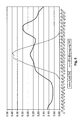
- FIG. 6 shows a mean PV (photovoltaic) power production and average load of a 6-person household. The surplus of PV power during lunch time is clearly visible.
- an inventive approach is to no longer try to feed produced PV energy directly and completely into the grid, but always feed just as much PV power into the grid as it is currently consuming and surplus Caching PV energy.
- the size of the memory to be used is defined by different parameters, such as: a .: size of the PV system, amount of own consumption, security needs of the user, cost effectiveness etc.
- FIG. 7 shows a meter concept for determining the self-consumption of self-generated energy.
- Counters 2 and 3 can be integrated into one device.
- the island grid according to the invention is able to provide the currently consumed amount of electricity as needed at the same time.
- the energy is provided either directly from the PV system, from the storage or even from a combination of both sources. Only if sufficient energy can not be made available from these sources is mains current used to increase, for example, at short notice Cover needs. If the network is not available due to a failure, the system will be able to save generated power and / or, as needed, provide backup services up to a defined size from those required by the sources.
- FIG. 8 illustrates an embodiment of the invention. Inverter, battery charger and battery modules are integrated in one device. In addition, a backup line is provided, which can supply loads up to the defined size in the event of a power failure.
- FIG. 8 shows a schematic representation of an island grid according to the invention for the optimization of PV-based self-consumption.
- the stand-alone grid integrates inverters, battery modules and battery charger in one device.
- another connection for the emergency supply is provided.
- the switches S1a and S1b are used to connect and disconnect loads to the emergency power supply and can be operated by the energy management
- the energy control device has an intelligent system management which regulates and monitors the energy flows and the function of the components.
- the energy management measures the current load on all three phases and thus determines the load to be provided by the inverter.
- the Battery Converter a charge controller with a very high efficiency, stores excess PV power into the batteries, or removes the difference between the PV power and the power to be fed.
- the power controller compensates for the highly dynamic power fluctuations characteristic of PV power and assists the inverter in providing the exact power.
- the system is equipped with a display to give the user and installer important information about the produced, stored and self-consumed electricity ( FIG. 9 ).
- the system provides a high degree of transparency regarding the performance of the own system and gives the installer important information about the system performance and supports it with any necessary maintenance work.
- FIG. 9 shows information about the plant performance provides a display
- the present invention has a variety of approaches. which have completely new ways of intelligent energy management for the power control device user.
- the system is constructed on top of that according to the kit principle, so that the installation by the specialist installer can be done easily.
- Existing PV systems can also be retrofitted.
Landscapes
- Engineering & Computer Science (AREA)
- Power Engineering (AREA)
- Supply And Distribution Of Alternating Current (AREA)
- Charge And Discharge Circuits For Batteries Or The Like (AREA)
Priority Applications (1)
| Application Number | Priority Date | Filing Date | Title |
|---|---|---|---|
| EP16206856.3A EP3182549A1 (fr) | 2009-09-04 | 2010-09-02 | Sol ion i: système individuel |
Applications Claiming Priority (1)
| Application Number | Priority Date | Filing Date | Title |
|---|---|---|---|
| DE102009040090A DE102009040090A1 (de) | 2009-09-04 | 2009-09-04 | Inseleinheit für ein Energienetz mit einer Steuereinheit zum Steuern eines Energieflusses zwischen der Energieerzeugungseinheit, der Energiespeichereinheit, der Lasteinheit und/oder dem Energienetz |
Related Child Applications (2)
| Application Number | Title | Priority Date | Filing Date |
|---|---|---|---|
| EP16206856.3A Division-Into EP3182549A1 (fr) | 2009-09-04 | 2010-09-02 | Sol ion i: système individuel |
| EP16206856.3A Division EP3182549A1 (fr) | 2009-09-04 | 2010-09-02 | Sol ion i: système individuel |
Publications (3)
| Publication Number | Publication Date |
|---|---|
| EP2293410A2 true EP2293410A2 (fr) | 2011-03-09 |
| EP2293410A3 EP2293410A3 (fr) | 2014-04-30 |
| EP2293410B1 EP2293410B1 (fr) | 2017-02-22 |
Family
ID=43301953
Family Applications (2)
| Application Number | Title | Priority Date | Filing Date |
|---|---|---|---|
| EP16206856.3A Withdrawn EP3182549A1 (fr) | 2009-09-04 | 2010-09-02 | Sol ion i: système individuel |
| EP10175112.1A Revoked EP2293410B1 (fr) | 2009-09-04 | 2010-09-02 | Dispositif de commande d'énergie pour un réseau d'énergie avec une unité de commande pour commander un flux d'énergie entre l'unité de production d'énergie, l'unité de stockage d'énergie, l'unité de chargement et/ou le réseau d'énergie |
Family Applications Before (1)
| Application Number | Title | Priority Date | Filing Date |
|---|---|---|---|
| EP16206856.3A Withdrawn EP3182549A1 (fr) | 2009-09-04 | 2010-09-02 | Sol ion i: système individuel |
Country Status (3)
| Country | Link |
|---|---|
| US (1) | US9099893B2 (fr) |
| EP (2) | EP3182549A1 (fr) |
| DE (1) | DE102009040090A1 (fr) |
Cited By (6)
| Publication number | Priority date | Publication date | Assignee | Title |
|---|---|---|---|---|
| ITTO20120008A1 (it) * | 2012-01-10 | 2013-07-11 | Gianluca Giannuzzi | Circuito e procedimento per l'accumulo di energia prodotta da sorgenti di energia rinnovabili. |
| WO2014140962A1 (fr) * | 2013-03-14 | 2014-09-18 | Koninklijke Philips N.V. | Système d'alimentation électrique solaire |
| DE102013213253A1 (de) * | 2013-07-05 | 2015-01-08 | Siemens Aktiengesellschaft | Verfahren und System zur Minimierung von Leistungsverlusten bei einem Energiespeicher |
| DE102014206892A1 (de) | 2013-08-26 | 2015-02-26 | Robert Bosch Gmbh | Verfahren und Steuergerät zum Betreiben eines Energiespeichers für eine Fotovoltaikanlage |
| EP2717410A4 (fr) * | 2011-05-24 | 2015-07-22 | Kyocera Corp | Dispositif de commande d'alimentation et procédé de commande d'alimentation |
| EP3082211A4 (fr) * | 2013-12-10 | 2017-01-04 | The Chugoku Electric Power Co., Inc. | Dispositif de commande de charge/décharge, et programme |
Families Citing this family (89)
| Publication number | Priority date | Publication date | Assignee | Title |
|---|---|---|---|---|
| US20080039979A1 (en) * | 2006-08-10 | 2008-02-14 | V2 Green Inc. | Smart Islanding and Power Backup in a Power Aggregation System for Distributed Electric Resources |
| US10295969B2 (en) | 2007-08-28 | 2019-05-21 | Causam Energy, Inc. | System and method for generating and providing dispatchable operating reserve energy capacity through use of active load management |
| US12438368B2 (en) | 2007-08-28 | 2025-10-07 | Causam Enterprises, Inc. | System and method for estimating and providing dispatchable operating reserve energy capacity through use of active load management |
| US9130402B2 (en) | 2007-08-28 | 2015-09-08 | Causam Energy, Inc. | System and method for generating and providing dispatchable operating reserve energy capacity through use of active load management |
| US9177323B2 (en) | 2007-08-28 | 2015-11-03 | Causam Energy, Inc. | Systems and methods for determining and utilizing customer energy profiles for load control for individual structures, devices, and aggregation of same |
| US8890505B2 (en) | 2007-08-28 | 2014-11-18 | Causam Energy, Inc. | System and method for estimating and providing dispatchable operating reserve energy capacity through use of active load management |
| US8806239B2 (en) | 2007-08-28 | 2014-08-12 | Causam Energy, Inc. | System, method, and apparatus for actively managing consumption of electric power supplied by one or more electric power grid operators |
| US8805552B2 (en) | 2007-08-28 | 2014-08-12 | Causam Energy, Inc. | Method and apparatus for actively managing consumption of electric power over an electric power grid |
| DE102009040090A1 (de) | 2009-09-04 | 2011-03-10 | Voltwerk Electronics Gmbh | Inseleinheit für ein Energienetz mit einer Steuereinheit zum Steuern eines Energieflusses zwischen der Energieerzeugungseinheit, der Energiespeichereinheit, der Lasteinheit und/oder dem Energienetz |
| DE102010032822A1 (de) * | 2010-04-21 | 2011-10-27 | Thomas Fricke | Stromerzeugungssystem und Verfahren zum Betreiben eines solchen |
| KR101713331B1 (ko) * | 2010-07-30 | 2017-03-08 | 삼성전자주식회사 | 에너지 공급 제어 방법 및 장치 |
| WO2012105105A1 (fr) | 2011-01-31 | 2012-08-09 | 日本電気株式会社 | Système de gestion d'énergie électrique et procédé de gestion d'énergie électrique |
| EP2528183B1 (fr) * | 2011-03-04 | 2014-04-02 | SBU Photovoltaik GmbH | Procédé et dispositif d'alimentation en courant |
| US20140091622A1 (en) * | 2011-04-15 | 2014-04-03 | Deka Products Limited Partnership | Modular Power Conversion System |
| WO2012165365A1 (fr) * | 2011-05-31 | 2012-12-06 | パナソニック株式会社 | Système d'alimentation électrique |
| EP2719049A2 (fr) * | 2011-06-07 | 2014-04-16 | N.V. Nederlandsche Apparatenfabriek NEDAP | Dispositif de commande d'électricité pour une installation électrique d'un bâtiment et procédé de commande d'électricité d'une installation électrique d'un bâtiment |
| RU2642422C2 (ru) | 2011-06-20 | 2018-01-25 | Те Аес Корпорейшн | Гибридная электростанция, в которой используется комбинирование генерирующих средств и системы аккумулирования энергии в режиме реального времени |
| WO2012176477A1 (fr) * | 2011-06-22 | 2012-12-27 | 京セラ株式会社 | Conditionneur de courant, procédé de commande et système de production de courant |
| DE102011056377A1 (de) | 2011-07-08 | 2013-01-10 | Mack Electronic Systems GmbH & Co. KG | Energiespeicher mit mindestens einem Basismodul |
| US8810202B2 (en) | 2011-07-15 | 2014-08-19 | Nec Corporation | Battery system and its control method |
| DE102011052467B4 (de) | 2011-08-08 | 2014-12-04 | tado GmbH | Nutzer-zustand und -verhalten basiertes steuerungssystem und -verfahren für gebäudetechnische systeme und komponenten |
| US9124098B2 (en) * | 2011-08-08 | 2015-09-01 | General Electric Company | Managing excess renewable energy |
| US8751036B2 (en) | 2011-09-28 | 2014-06-10 | Causam Energy, Inc. | Systems and methods for microgrid power generation management with selective disconnect |
| US8862279B2 (en) | 2011-09-28 | 2014-10-14 | Causam Energy, Inc. | Systems and methods for optimizing microgrid power generation and management with predictive modeling |
| US9225173B2 (en) | 2011-09-28 | 2015-12-29 | Causam Energy, Inc. | Systems and methods for microgrid power generation and management |
| DE102011055231A1 (de) | 2011-11-10 | 2013-05-16 | Evonik Industries Ag | Verfahren zur Bereitstellung von Regelleistung |
| DE102011055225A1 (de) * | 2011-11-10 | 2013-05-16 | Evonik Degussa Gmbh | Verfahren zur Bereitstellung von Regelleistung |
| WO2013079067A1 (fr) * | 2011-11-29 | 2013-06-06 | Danfoss Power Electronics A/S | Convertisseur avec dispositif de stockage |
| DE102011089588A1 (de) * | 2011-12-22 | 2012-11-15 | Siemens Aktiengesellschaft | Einrichtung zur Ermittlung einer elektrischen Größe, insbesondere eines elektrischen Netzes |
| JP2013183577A (ja) * | 2012-03-02 | 2013-09-12 | Kyocera Corp | 電力制御システム、電力制御装置、及び電力制御方法 |
| US9461471B2 (en) | 2012-06-20 | 2016-10-04 | Causam Energy, Inc | System and methods for actively managing electric power over an electric power grid and providing revenue grade date usable for settlement |
| US9207698B2 (en) | 2012-06-20 | 2015-12-08 | Causam Energy, Inc. | Method and apparatus for actively managing electric power over an electric power grid |
| DE102012210396A1 (de) * | 2012-06-20 | 2013-12-24 | Robert Bosch Gmbh | Betriebsverfahren und Betriebsvorrichtung für einen elektrischen Energiespeicher eines Kleinkraftwerkes zum Erhöhen der Betriebseffektivität des Kleinkraftwerkes |
| US9465398B2 (en) | 2012-06-20 | 2016-10-11 | Causam Energy, Inc. | System and methods for actively managing electric power over an electric power grid |
| DE102012212321A1 (de) * | 2012-07-13 | 2014-01-16 | Robert Bosch Gmbh | Vorrichtung zum Ermitteln und/oder Steuern einer Betriebszeit eines mit einem Kraftwerk, insbesondere Photovoltaikkraftwerk, und einem Energiespeicher gekoppelten Verbrauchers, und Verfahren zum Betreiben eines mit einem Kraftwerk gekoppelten Energiespeichers |
| US9563215B2 (en) | 2012-07-14 | 2017-02-07 | Causam Energy, Inc. | Method and apparatus for actively managing electric power supply for an electric power grid |
| US9356447B2 (en) | 2012-07-24 | 2016-05-31 | International Business Machines Corporation | Predictive phase balancing for demand response |
| US10475138B2 (en) | 2015-09-23 | 2019-11-12 | Causam Energy, Inc. | Systems and methods for advanced energy network |
| US8983669B2 (en) | 2012-07-31 | 2015-03-17 | Causam Energy, Inc. | System, method, and data packets for messaging for electric power grid elements over a secure internet protocol network |
| US10861112B2 (en) | 2012-07-31 | 2020-12-08 | Causam Energy, Inc. | Systems and methods for advanced energy settlements, network-based messaging, and applications supporting the same on a blockchain platform |
| US9513648B2 (en) | 2012-07-31 | 2016-12-06 | Causam Energy, Inc. | System, method, and apparatus for electric power grid and network management of grid elements |
| US8849715B2 (en) * | 2012-10-24 | 2014-09-30 | Causam Energy, Inc. | System, method, and apparatus for settlement for participation in an electric power grid |
| US10782721B2 (en) * | 2012-08-27 | 2020-09-22 | Stem, Inc. | Method and apparatus for balancing power on a per phase basis in multi-phase electrical load facilities using an energy storage system |
| US11454999B2 (en) * | 2012-08-29 | 2022-09-27 | Stem, Inc. | Method and apparatus for automatically reconfiguring multi-phased networked energy storage devices at a site |
| DE202012008606U1 (de) | 2012-09-10 | 2013-12-12 | Robert Bosch Gmbh | Solarspeichersystem |
| US10289080B2 (en) | 2012-10-11 | 2019-05-14 | Flexgen Power Systems, Inc. | Multi-generator applications using variable speed and solid state generators for efficiency and frequency stabilization |
| US9312699B2 (en) | 2012-10-11 | 2016-04-12 | Flexgen Power Systems, Inc. | Island grid power supply apparatus and methods using energy storage for transient stabilization |
| US9444397B2 (en) | 2012-10-26 | 2016-09-13 | Sunculture Solar, Inc. | Integrated solar panel |
| US9620993B2 (en) | 2012-10-26 | 2017-04-11 | Solpad, Inc. | Auto-synchronous isolated inlet power converter |
| US9948139B2 (en) | 2012-10-26 | 2018-04-17 | Solpad, Inc. | Solar power generation, distribution, and communication system |
| US9711967B1 (en) * | 2012-11-06 | 2017-07-18 | Reliance Conrtols Corporation | Off grid backup inverter automatic transfer switch |
| DE102013221750A1 (de) * | 2012-11-15 | 2014-05-15 | Siemens Aktiengesellschaft | Verfahren zur rechnergestützten Steuerung der Leistung in einem elektrischen Stromnetz |
| US9553517B2 (en) | 2013-03-01 | 2017-01-24 | Fllexgen Power Systems, Inc. | Hybrid energy storage system and methods |
| FR3004023B1 (fr) | 2013-03-28 | 2017-02-24 | Energie Durable | Systeme automatique de gestion de la production et de la consommation d'electricite. |
| US9270164B2 (en) | 2013-06-19 | 2016-02-23 | Tmeic Corporation | Methods, systems, computer program products, and devices for renewable energy site power limit control |
| DE102013011087A1 (de) * | 2013-07-03 | 2015-01-08 | RWE Supply & Trading GmbH | Verfahren zur Regelung des Gasbezuges für mehrere Gasverbraucher aus einem Gastransportnetz |
| DE102013217576A1 (de) * | 2013-09-04 | 2015-03-05 | Robert Bosch Gmbh | Verfahren und Vorrichtung zur adaptiven Betriebsführung für ein Speichersystem für ein Fotovoltaiksystem |
| ES2973287T3 (es) | 2013-09-26 | 2024-06-19 | Wellhead Power Solutions Llc | Sistema y método energético híbridos |
| US9722426B2 (en) | 2013-09-26 | 2017-08-01 | Wellhead Electric Company, Inc. | Hybrid energy system and method |
| US9728974B2 (en) | 2013-10-10 | 2017-08-08 | Tmeic Corporation | Renewable energy site reactive power control |
| US10116560B2 (en) | 2014-10-20 | 2018-10-30 | Causam Energy, Inc. | Systems, methods, and apparatus for communicating messages of distributed private networks over multiple public communication networks |
| US10574055B2 (en) | 2014-12-30 | 2020-02-25 | Flexgen Power Systems, Inc. | Transient power stabilization device with active and reactive power control |
| DE102015107554A1 (de) * | 2015-05-13 | 2016-11-17 | Sonnenbatterie Gmbh | Energieanlage, Wechselrichter und Verfahren zum Betreiben eines Wechselrichters |
| TWI558054B (zh) * | 2015-09-14 | 2016-11-11 | Bin Juine Huang | Multi - group regional mutual - aid power generation system |
| US10180696B2 (en) | 2015-12-08 | 2019-01-15 | Smart Wires Inc. | Distributed impedance injection module for mitigation of the Ferranti effect |
| US10008317B2 (en) | 2015-12-08 | 2018-06-26 | Smart Wires Inc. | Voltage or impedance-injection method using transformers with multiple secondary windings for dynamic power flow control |
| US10418814B2 (en) | 2015-12-08 | 2019-09-17 | Smart Wires Inc. | Transformers with multi-turn primary windings for dynamic power flow control |
| US10903653B2 (en) | 2015-12-08 | 2021-01-26 | Smart Wires Inc. | Voltage agnostic power reactor |
| US10199150B2 (en) | 2015-12-10 | 2019-02-05 | Smart Wires Inc. | Power transmission tower mounted series injection transformer |
| US10348092B1 (en) | 2016-01-19 | 2019-07-09 | Noel Diaz | Electrical power distribution control device |
| US10218175B2 (en) | 2016-02-11 | 2019-02-26 | Smart Wires Inc. | Dynamic and integrated control of total power system using distributed impedance injection modules and actuator devices within and at the edge of the power grid |
| US10097037B2 (en) | 2016-02-11 | 2018-10-09 | Smart Wires Inc. | System and method for distributed grid control with sub-cyclic local response capability |
| US10651633B2 (en) | 2016-04-22 | 2020-05-12 | Smart Wires Inc. | Modular, space-efficient structures mounting multiple electrical devices |
| US10139847B2 (en) * | 2016-05-18 | 2018-11-27 | Solarcity Corporation | Systems and methods for controlling PV production within energy export constraints |
| US10468880B2 (en) | 2016-11-15 | 2019-11-05 | Smart Wires Inc. | Systems and methods for voltage regulation using split-conductors with loop current reduction |
| US9645596B1 (en) * | 2016-11-23 | 2017-05-09 | Advanced Microgrid Solutions, Inc. | Method and apparatus for facilitating the operation of an on-site energy storage system to co-optimize battery dispatch |
| ES2680654B1 (es) * | 2017-02-07 | 2019-05-08 | Univ Huelva | Método y dispositivo de intercambio sincronizado de energía entre usuarios de la red eléctrica para la gestíón descentralizada |
| DE102017203249A1 (de) * | 2017-02-28 | 2018-08-30 | Viessmann Werke Gmbh & Co Kg | Energiemanagement-Verfahren für ein Energiesystem und Energiesystem |
| US10693296B2 (en) | 2017-05-03 | 2020-06-23 | International Business Machines Corporation | Stabilizing consumer energy demand |
| US10666038B2 (en) | 2017-06-30 | 2020-05-26 | Smart Wires Inc. | Modular FACTS devices with external fault current protection |
| DE102017118706A1 (de) * | 2017-08-16 | 2019-02-21 | IBF Ingenieurbüro Fehringer GmbH | Bidirektionale Solartankstelle sowie Verfahren zum Betrieb einer Solartankstelle |
| DE102017009794A1 (de) * | 2017-10-20 | 2019-04-25 | Allion Alternative Energieanlagen Gmbh | Energieversorgungsvorrichtung und Verfahren zum Betreiben einer Energieversorgungsvorrichtung |
| US10756570B2 (en) * | 2018-03-09 | 2020-08-25 | Alliance For Sustainable Energy, Llc | Coordinated net-load management |
| DE102018206214A1 (de) * | 2018-04-23 | 2019-10-24 | Viessmann Werke Gmbh & Co. Kg | Verfahren zum Betreiben eines Energieversorgungssystems |
| US10742037B2 (en) | 2018-07-02 | 2020-08-11 | International Business Machines Corporation | Managing consumer energy demand |
| EP4254784A3 (fr) * | 2020-05-04 | 2023-12-20 | 8Me Nova, Llc | Systèmes et procédés utilisant une ressource de génération électrique renouvelable surchargée à courant alternatif et dispositif de stockage de charge |
| US11081887B1 (en) | 2020-05-04 | 2021-08-03 | 8Me Nova, Llc | Systems and methods utilizing AC overbuilt renewable electric generation resource and charge storage device providing desired capacity factor |
| EP4293854A4 (fr) * | 2021-03-02 | 2024-08-14 | Huawei Digital Power Technologies Co., Ltd. | Procédé de réalisation d'une réponse en puissance rapide, et nouvelle centrale électrique |
| US20240383421A1 (en) * | 2023-05-19 | 2024-11-21 | Bauer Energy Solution, Llc | Integrated energy storage device |
Citations (4)
| Publication number | Priority date | Publication date | Assignee | Title |
|---|---|---|---|---|
| DE10018943A1 (de) | 2000-04-17 | 2001-10-31 | Inst Luft Kaeltetech Gem Gmbh | Photovoltaik-Wechselrichter |
| EP1848085A2 (fr) | 2006-04-20 | 2007-10-24 | N.V. Nederlandsche Apparatenfabriek NEDAP | Système de bus modulaire et bidirectionnel pour échanger de l'énergie entre modules |
| WO2008125696A2 (fr) | 2007-04-17 | 2008-10-23 | Timothy Patrick Cooper | Dispositif de contrôle de charges |
| GB2455421A (en) | 2007-12-07 | 2009-06-10 | David Bruce Withington | Storage, distribution and supply of locally generated electricity |
Family Cites Families (15)
| Publication number | Priority date | Publication date | Assignee | Title |
|---|---|---|---|---|
| JP3634731B2 (ja) * | 2000-09-21 | 2005-03-30 | シャープ株式会社 | 太陽光発電管理システム、そのシステムに用いられる太陽光発電管理サーバおよび太陽光発電装置 |
| WO2002039563A1 (fr) * | 2000-11-09 | 2002-05-16 | Berner Fachhochschule Hochschule Für Technik Und Architektur Biel-Bienne | Dispositif chargeur de batteries et procede permettant de charger des batteries a plusieurs blocs de batteries |
| JP2003079054A (ja) | 2001-08-31 | 2003-03-14 | Sanyo Electric Co Ltd | 蓄電池を備えた太陽光発電システム |
| EP1623495B1 (fr) | 2003-05-06 | 2009-10-07 | Enecsys Limited | Circuits d'alimentation electrique |
| US7274975B2 (en) * | 2005-06-06 | 2007-09-25 | Gridpoint, Inc. | Optimized energy management system |
| JP5124114B2 (ja) | 2006-08-28 | 2013-01-23 | シャープ株式会社 | 蓄電機能を有するパワーコンディショナ |
| WO2008047400A1 (fr) * | 2006-10-16 | 2008-04-24 | Vpec, Inc. | Système d'alimentation électrique |
| RU2475923C2 (ru) * | 2007-05-08 | 2013-02-20 | Американ Пауэр Конвершн Корпорейшн | Управление энергией альтернативных источников |
| WO2009046533A1 (fr) * | 2007-10-11 | 2009-04-16 | Icp Global Technologies Inc. | Contrôleur autonome d'énergie renouvelable hybride |
| US7925552B2 (en) * | 2008-03-13 | 2011-04-12 | Solarcity Corporation | Renewable energy system monitor |
| WO2009155445A2 (fr) | 2008-06-18 | 2009-12-23 | Premium Power Corporation | Systèmes de production et de stockage d'énergie renouvelable intégrés et procédés associés |
| DE202008016967U1 (de) | 2008-12-20 | 2009-03-26 | Martin Jaiser und Udo Mürle GbR (vertretungsberechtigter Gesellschafter: Herrn Udo Mürle, 75181 Pforzheim) | Steuereinheit zum Energieflussmanagement von Stromverbrauch und Einspeisung an Stromnetzen |
| US8352091B2 (en) * | 2009-01-02 | 2013-01-08 | International Business Machines Corporation | Distributed grid-interactive photovoltaic-based power dispatching |
| US8008808B2 (en) | 2009-01-16 | 2011-08-30 | Zbb Energy Corporation | Method and apparatus for controlling a hybrid power system |
| DE102009040090A1 (de) | 2009-09-04 | 2011-03-10 | Voltwerk Electronics Gmbh | Inseleinheit für ein Energienetz mit einer Steuereinheit zum Steuern eines Energieflusses zwischen der Energieerzeugungseinheit, der Energiespeichereinheit, der Lasteinheit und/oder dem Energienetz |
-
2009
- 2009-09-04 DE DE102009040090A patent/DE102009040090A1/de not_active Ceased
-
2010
- 2010-09-02 EP EP16206856.3A patent/EP3182549A1/fr not_active Withdrawn
- 2010-09-02 EP EP10175112.1A patent/EP2293410B1/fr not_active Revoked
- 2010-09-03 US US12/875,942 patent/US9099893B2/en active Active
Patent Citations (4)
| Publication number | Priority date | Publication date | Assignee | Title |
|---|---|---|---|---|
| DE10018943A1 (de) | 2000-04-17 | 2001-10-31 | Inst Luft Kaeltetech Gem Gmbh | Photovoltaik-Wechselrichter |
| EP1848085A2 (fr) | 2006-04-20 | 2007-10-24 | N.V. Nederlandsche Apparatenfabriek NEDAP | Système de bus modulaire et bidirectionnel pour échanger de l'énergie entre modules |
| WO2008125696A2 (fr) | 2007-04-17 | 2008-10-23 | Timothy Patrick Cooper | Dispositif de contrôle de charges |
| GB2455421A (en) | 2007-12-07 | 2009-06-10 | David Bruce Withington | Storage, distribution and supply of locally generated electricity |
Cited By (7)
| Publication number | Priority date | Publication date | Assignee | Title |
|---|---|---|---|---|
| EP2717410A4 (fr) * | 2011-05-24 | 2015-07-22 | Kyocera Corp | Dispositif de commande d'alimentation et procédé de commande d'alimentation |
| ITTO20120008A1 (it) * | 2012-01-10 | 2013-07-11 | Gianluca Giannuzzi | Circuito e procedimento per l'accumulo di energia prodotta da sorgenti di energia rinnovabili. |
| EP2615710A1 (fr) * | 2012-01-10 | 2013-07-17 | DG ECOENERGY S.a.s. di Diego Federico Giannuzzi & C. | Circuit et procédé pour accumuler l'énergie produite par des sources renouvelables |
| WO2014140962A1 (fr) * | 2013-03-14 | 2014-09-18 | Koninklijke Philips N.V. | Système d'alimentation électrique solaire |
| DE102013213253A1 (de) * | 2013-07-05 | 2015-01-08 | Siemens Aktiengesellschaft | Verfahren und System zur Minimierung von Leistungsverlusten bei einem Energiespeicher |
| DE102014206892A1 (de) | 2013-08-26 | 2015-02-26 | Robert Bosch Gmbh | Verfahren und Steuergerät zum Betreiben eines Energiespeichers für eine Fotovoltaikanlage |
| EP3082211A4 (fr) * | 2013-12-10 | 2017-01-04 | The Chugoku Electric Power Co., Inc. | Dispositif de commande de charge/décharge, et programme |
Also Published As
| Publication number | Publication date |
|---|---|
| EP2293410B1 (fr) | 2017-02-22 |
| US20110060474A1 (en) | 2011-03-10 |
| EP2293410A3 (fr) | 2014-04-30 |
| US9099893B2 (en) | 2015-08-04 |
| EP3182549A1 (fr) | 2017-06-21 |
| DE102009040090A1 (de) | 2011-03-10 |
Similar Documents
| Publication | Publication Date | Title |
|---|---|---|
| EP2293410B1 (fr) | Dispositif de commande d'énergie pour un réseau d'énergie avec une unité de commande pour commander un flux d'énergie entre l'unité de production d'énergie, l'unité de stockage d'énergie, l'unité de chargement et/ou le réseau d'énergie | |
| EP2293409B1 (fr) | Unité d'îlot d'un réseau d'énergie en îlot pour la communication de demandes d'énergie avec une autre unité d'îlot | |
| EP3288141A1 (fr) | Système automatisé de stockage d'énergie dans une batterie et centrale de génération d'électricité, de stabilisation du réseau, d'alimentation en énergie de réserve | |
| EP1485978B1 (fr) | Reseau separe et son mode de fonctionnement | |
| DE202012013452U1 (de) | Mischen und Glätten von Stromversorgungsquellen | |
| EP3031112B1 (fr) | Système et procédé de régulation de la fréquence et/ou de la tension d'un réseau de transport à partir du réseau de distribution | |
| WO2012136346A1 (fr) | Dispositif de distribution d'énergie électrique pour un immeuble | |
| DE102015101738B4 (de) | Verfahren zum Betrieb einer Energieerzeugungsanlage und Energieerzeugungsanlage | |
| EP2826121A1 (fr) | Procédé de commande d'un système pour alimenter un réseau d'alimentation en courant électrique | |
| DE102008044842A1 (de) | Vorrichtung zur Energieversorgung eines Bahnnetzes | |
| DE102011090141A1 (de) | Verfahren und Vorrichtung zur Nutzung elektrischer Energie einer an ein Hausstromnetz angeschlossenen Einrichtung zur Erzeugung erneuerbarer elektrischer Energie | |
| EP2777120A2 (fr) | Procede pour fournir une puissance de régulation en utilisant des accumulateurs d'énergie | |
| EP2777124A1 (fr) | Procede pour fournir une puissance de régulation au moyen d'un accumulateur d'énergie en mettant a profit des tolerances lors de la fourniture de la puissance | |
| DE102011055225A1 (de) | Verfahren zur Bereitstellung von Regelleistung | |
| WO2013045072A2 (fr) | Installation photovoltaïque comportant une sécurité contre l'injection dans un réseau électrique public | |
| WO2014023724A2 (fr) | Système accumulateur photovoltaïque | |
| EP2026440A2 (fr) | Procédé et dispositif de préparation d'une puissance de régulation dans le domaine de la distribution d'énergie d'un distributeur d'énergie en vue de la stabilisation de la fréquence d'un réseau électrique | |
| DE102010000350B4 (de) | Energieversorgungssystem mit regenerativer Stromquelle und Verfahren zum Betrieb eines Energieversorgungssystems | |
| WO2013064377A2 (fr) | Unité d'alimentation et ensemble générateur et consommateur de courant | |
| DE102011010791A1 (de) | System zur Erzeugung regenerativer elektrischer Energie mit intelligenter Energieverwaltungseinheit | |
| EP2626969A2 (fr) | Installation de production d'énergie avec un onduleur et système de stockage d'énergie | |
| DE202012101240U1 (de) | Energiemanagementsystem | |
| DE202011102374U1 (de) | Energiespeicher- und/oder Versorgungsvorrichtung | |
| DE102019214768A1 (de) | Verfahren und Vorrichtung zur Verwendung von freien Netzkapazitäten für Ladevorgänge von Elektrofahrzeugen | |
| DE102023101968A1 (de) | Eine Wärmepumpe und mindestens einen weiteren elektrischen Verbraucher umfassende Anlage |
Legal Events
| Date | Code | Title | Description |
|---|---|---|---|
| PUAI | Public reference made under article 153(3) epc to a published international application that has entered the european phase |
Free format text: ORIGINAL CODE: 0009012 |
|
| AK | Designated contracting states |
Kind code of ref document: A2 Designated state(s): AL AT BE BG CH CY CZ DE DK EE ES FI FR GB GR HR HU IE IS IT LI LT LU LV MC MK MT NL NO PL PT RO SE SI SK SM TR |
|
| AX | Request for extension of the european patent |
Extension state: BA ME RS |
|
| RAP1 | Party data changed (applicant data changed or rights of an application transferred) |
Owner name: ROBERT BOSCH GMBH |
|
| PUAL | Search report despatched |
Free format text: ORIGINAL CODE: 0009013 |
|
| AK | Designated contracting states |
Kind code of ref document: A3 Designated state(s): AL AT BE BG CH CY CZ DE DK EE ES FI FR GB GR HR HU IE IS IT LI LT LU LV MC MK MT NL NO PL PT RO SE SI SK SM TR |
|
| AX | Request for extension of the european patent |
Extension state: BA ME RS |
|
| RIC1 | Information provided on ipc code assigned before grant |
Ipc: H02J 3/38 20060101AFI20140321BHEP Ipc: H02J 7/35 20060101ALI20140321BHEP |
|
| 17P | Request for examination filed |
Effective date: 20140804 |
|
| RBV | Designated contracting states (corrected) |
Designated state(s): AL AT BE BG CH CY CZ DE DK EE ES FI FR GB GR HR HU IE IS IT LI LT LU LV MC MK MT NL NO PL PT RO SE SI SK SM TR |
|
| 17Q | First examination report despatched |
Effective date: 20151112 |
|
| GRAP | Despatch of communication of intention to grant a patent |
Free format text: ORIGINAL CODE: EPIDOSNIGR1 |
|
| INTG | Intention to grant announced |
Effective date: 20160902 |
|
| RIN1 | Information on inventor provided before grant (corrected) |
Inventor name: BUEPPELMANN, RALF Inventor name: HEIMFARTH, STEFAN DIETER Inventor name: SCHMIEGEL, DR. ARMIN UWE |
|
| STAA | Information on the status of an ep patent application or granted ep patent |
Free format text: STATUS: GRANT OF PATENT IS INTENDED |
|
| GRAS | Grant fee paid |
Free format text: ORIGINAL CODE: EPIDOSNIGR3 |
|
| GRAA | (expected) grant |
Free format text: ORIGINAL CODE: 0009210 |
|
| STAA | Information on the status of an ep patent application or granted ep patent |
Free format text: STATUS: THE PATENT HAS BEEN GRANTED |
|
| AK | Designated contracting states |
Kind code of ref document: B1 Designated state(s): AL AT BE BG CH CY CZ DE DK EE ES FI FR GB GR HR HU IE IS IT LI LT LU LV MC MK MT NL NO PL PT RO SE SI SK SM TR |
|
| REG | Reference to a national code |
Ref country code: GB Ref legal event code: FG4D Free format text: NOT ENGLISH |
|
| REG | Reference to a national code |
Ref country code: CH Ref legal event code: EP |
|
| REG | Reference to a national code |
Ref country code: AT Ref legal event code: REF Ref document number: 869959 Country of ref document: AT Kind code of ref document: T Effective date: 20170315 |
|
| REG | Reference to a national code |
Ref country code: IE Ref legal event code: FG4D Free format text: LANGUAGE OF EP DOCUMENT: GERMAN |
|
| REG | Reference to a national code |
Ref country code: DE Ref legal event code: R096 Ref document number: 502010013195 Country of ref document: DE |
|
| REG | Reference to a national code |
Ref country code: LT Ref legal event code: MG4D |
|
| REG | Reference to a national code |
Ref country code: NL Ref legal event code: MP Effective date: 20170222 |
|
| PG25 | Lapsed in a contracting state [announced via postgrant information from national office to epo] |
Ref country code: NO Free format text: LAPSE BECAUSE OF FAILURE TO SUBMIT A TRANSLATION OF THE DESCRIPTION OR TO PAY THE FEE WITHIN THE PRESCRIBED TIME-LIMIT Effective date: 20170522 Ref country code: LT Free format text: LAPSE BECAUSE OF FAILURE TO SUBMIT A TRANSLATION OF THE DESCRIPTION OR TO PAY THE FEE WITHIN THE PRESCRIBED TIME-LIMIT Effective date: 20170222 Ref country code: HR Free format text: LAPSE BECAUSE OF FAILURE TO SUBMIT A TRANSLATION OF THE DESCRIPTION OR TO PAY THE FEE WITHIN THE PRESCRIBED TIME-LIMIT Effective date: 20170222 Ref country code: GR Free format text: LAPSE BECAUSE OF FAILURE TO SUBMIT A TRANSLATION OF THE DESCRIPTION OR TO PAY THE FEE WITHIN THE PRESCRIBED TIME-LIMIT Effective date: 20170523 Ref country code: FI Free format text: LAPSE BECAUSE OF FAILURE TO SUBMIT A TRANSLATION OF THE DESCRIPTION OR TO PAY THE FEE WITHIN THE PRESCRIBED TIME-LIMIT Effective date: 20170222 |
|
| PG25 | Lapsed in a contracting state [announced via postgrant information from national office to epo] |
Ref country code: ES Free format text: LAPSE BECAUSE OF FAILURE TO SUBMIT A TRANSLATION OF THE DESCRIPTION OR TO PAY THE FEE WITHIN THE PRESCRIBED TIME-LIMIT Effective date: 20170222 Ref country code: LV Free format text: LAPSE BECAUSE OF FAILURE TO SUBMIT A TRANSLATION OF THE DESCRIPTION OR TO PAY THE FEE WITHIN THE PRESCRIBED TIME-LIMIT Effective date: 20170222 Ref country code: NL Free format text: LAPSE BECAUSE OF FAILURE TO SUBMIT A TRANSLATION OF THE DESCRIPTION OR TO PAY THE FEE WITHIN THE PRESCRIBED TIME-LIMIT Effective date: 20170222 Ref country code: PT Free format text: LAPSE BECAUSE OF FAILURE TO SUBMIT A TRANSLATION OF THE DESCRIPTION OR TO PAY THE FEE WITHIN THE PRESCRIBED TIME-LIMIT Effective date: 20170622 Ref country code: SE Free format text: LAPSE BECAUSE OF FAILURE TO SUBMIT A TRANSLATION OF THE DESCRIPTION OR TO PAY THE FEE WITHIN THE PRESCRIBED TIME-LIMIT Effective date: 20170222 Ref country code: BG Free format text: LAPSE BECAUSE OF FAILURE TO SUBMIT A TRANSLATION OF THE DESCRIPTION OR TO PAY THE FEE WITHIN THE PRESCRIBED TIME-LIMIT Effective date: 20170522 |
|
| REG | Reference to a national code |
Ref country code: FR Ref legal event code: PLFP Year of fee payment: 8 |
|
| PG25 | Lapsed in a contracting state [announced via postgrant information from national office to epo] |
Ref country code: IT Free format text: LAPSE BECAUSE OF FAILURE TO SUBMIT A TRANSLATION OF THE DESCRIPTION OR TO PAY THE FEE WITHIN THE PRESCRIBED TIME-LIMIT Effective date: 20170222 Ref country code: SK Free format text: LAPSE BECAUSE OF FAILURE TO SUBMIT A TRANSLATION OF THE DESCRIPTION OR TO PAY THE FEE WITHIN THE PRESCRIBED TIME-LIMIT Effective date: 20170222 Ref country code: CZ Free format text: LAPSE BECAUSE OF FAILURE TO SUBMIT A TRANSLATION OF THE DESCRIPTION OR TO PAY THE FEE WITHIN THE PRESCRIBED TIME-LIMIT Effective date: 20170222 Ref country code: RO Free format text: LAPSE BECAUSE OF FAILURE TO SUBMIT A TRANSLATION OF THE DESCRIPTION OR TO PAY THE FEE WITHIN THE PRESCRIBED TIME-LIMIT Effective date: 20170222 Ref country code: EE Free format text: LAPSE BECAUSE OF FAILURE TO SUBMIT A TRANSLATION OF THE DESCRIPTION OR TO PAY THE FEE WITHIN THE PRESCRIBED TIME-LIMIT Effective date: 20170222 |
|
| REG | Reference to a national code |
Ref country code: DE Ref legal event code: R026 Ref document number: 502010013195 Country of ref document: DE |
|
| PLBI | Opposition filed |
Free format text: ORIGINAL CODE: 0009260 |
|
| PG25 | Lapsed in a contracting state [announced via postgrant information from national office to epo] |
Ref country code: DK Free format text: LAPSE BECAUSE OF FAILURE TO SUBMIT A TRANSLATION OF THE DESCRIPTION OR TO PAY THE FEE WITHIN THE PRESCRIBED TIME-LIMIT Effective date: 20170222 Ref country code: PL Free format text: LAPSE BECAUSE OF FAILURE TO SUBMIT A TRANSLATION OF THE DESCRIPTION OR TO PAY THE FEE WITHIN THE PRESCRIBED TIME-LIMIT Effective date: 20170222 Ref country code: SM Free format text: LAPSE BECAUSE OF FAILURE TO SUBMIT A TRANSLATION OF THE DESCRIPTION OR TO PAY THE FEE WITHIN THE PRESCRIBED TIME-LIMIT Effective date: 20170222 |
|
| PLBI | Opposition filed |
Free format text: ORIGINAL CODE: 0009260 |
|
| PLAX | Notice of opposition and request to file observation + time limit sent |
Free format text: ORIGINAL CODE: EPIDOSNOBS2 |
|
| 26 | Opposition filed |
Opponent name: SMA SOLAR TECHNOLOGY AG Effective date: 20171122 |
|
| 26 | Opposition filed |
Opponent name: SONNEN GMBH Effective date: 20171122 |
|
| PG25 | Lapsed in a contracting state [announced via postgrant information from national office to epo] |
Ref country code: SI Free format text: LAPSE BECAUSE OF FAILURE TO SUBMIT A TRANSLATION OF THE DESCRIPTION OR TO PAY THE FEE WITHIN THE PRESCRIBED TIME-LIMIT Effective date: 20170222 |
|
| PLBB | Reply of patent proprietor to notice(s) of opposition received |
Free format text: ORIGINAL CODE: EPIDOSNOBS3 |
|
| REG | Reference to a national code |
Ref country code: CH Ref legal event code: PL |
|
| PG25 | Lapsed in a contracting state [announced via postgrant information from national office to epo] |
Ref country code: MC Free format text: LAPSE BECAUSE OF FAILURE TO SUBMIT A TRANSLATION OF THE DESCRIPTION OR TO PAY THE FEE WITHIN THE PRESCRIBED TIME-LIMIT Effective date: 20170222 |
|
| REG | Reference to a national code |
Ref country code: IE Ref legal event code: MM4A |
|
| REG | Reference to a national code |
Ref country code: BE Ref legal event code: MM Effective date: 20170930 |
|
| PG25 | Lapsed in a contracting state [announced via postgrant information from national office to epo] |
Ref country code: LU Free format text: LAPSE BECAUSE OF NON-PAYMENT OF DUE FEES Effective date: 20170902 |
|
| PG25 | Lapsed in a contracting state [announced via postgrant information from national office to epo] |
Ref country code: CH Free format text: LAPSE BECAUSE OF NON-PAYMENT OF DUE FEES Effective date: 20170930 Ref country code: IE Free format text: LAPSE BECAUSE OF NON-PAYMENT OF DUE FEES Effective date: 20170902 Ref country code: LI Free format text: LAPSE BECAUSE OF NON-PAYMENT OF DUE FEES Effective date: 20170930 |
|
| PG25 | Lapsed in a contracting state [announced via postgrant information from national office to epo] |
Ref country code: BE Free format text: LAPSE BECAUSE OF NON-PAYMENT OF DUE FEES Effective date: 20170930 |
|
| REG | Reference to a national code |
Ref country code: FR Ref legal event code: PLFP Year of fee payment: 9 |
|
| PG25 | Lapsed in a contracting state [announced via postgrant information from national office to epo] |
Ref country code: MT Free format text: LAPSE BECAUSE OF FAILURE TO SUBMIT A TRANSLATION OF THE DESCRIPTION OR TO PAY THE FEE WITHIN THE PRESCRIBED TIME-LIMIT Effective date: 20170222 |
|
| REG | Reference to a national code |
Ref country code: AT Ref legal event code: MM01 Ref document number: 869959 Country of ref document: AT Kind code of ref document: T Effective date: 20170902 |
|
| PG25 | Lapsed in a contracting state [announced via postgrant information from national office to epo] |
Ref country code: AT Free format text: LAPSE BECAUSE OF NON-PAYMENT OF DUE FEES Effective date: 20170902 |
|
| RDAF | Communication despatched that patent is revoked |
Free format text: ORIGINAL CODE: EPIDOSNREV1 |
|
| PG25 | Lapsed in a contracting state [announced via postgrant information from national office to epo] |
Ref country code: HU Free format text: LAPSE BECAUSE OF FAILURE TO SUBMIT A TRANSLATION OF THE DESCRIPTION OR TO PAY THE FEE WITHIN THE PRESCRIBED TIME-LIMIT; INVALID AB INITIO Effective date: 20100902 |
|
| APBM | Appeal reference recorded |
Free format text: ORIGINAL CODE: EPIDOSNREFNO |
|
| APBP | Date of receipt of notice of appeal recorded |
Free format text: ORIGINAL CODE: EPIDOSNNOA2O |
|
| APAH | Appeal reference modified |
Free format text: ORIGINAL CODE: EPIDOSCREFNO |
|
| APBQ | Date of receipt of statement of grounds of appeal recorded |
Free format text: ORIGINAL CODE: EPIDOSNNOA3O |
|
| PG25 | Lapsed in a contracting state [announced via postgrant information from national office to epo] |
Ref country code: CY Free format text: LAPSE BECAUSE OF NON-PAYMENT OF DUE FEES Effective date: 20170222 |
|
| PG25 | Lapsed in a contracting state [announced via postgrant information from national office to epo] |
Ref country code: MK Free format text: LAPSE BECAUSE OF FAILURE TO SUBMIT A TRANSLATION OF THE DESCRIPTION OR TO PAY THE FEE WITHIN THE PRESCRIBED TIME-LIMIT Effective date: 20170222 |
|
| PG25 | Lapsed in a contracting state [announced via postgrant information from national office to epo] |
Ref country code: TR Free format text: LAPSE BECAUSE OF FAILURE TO SUBMIT A TRANSLATION OF THE DESCRIPTION OR TO PAY THE FEE WITHIN THE PRESCRIBED TIME-LIMIT Effective date: 20170222 |
|
| RAP2 | Party data changed (patent owner data changed or rights of a patent transferred) |
Owner name: ROBERT BOSCH GMBH |
|
| PG25 | Lapsed in a contracting state [announced via postgrant information from national office to epo] |
Ref country code: AL Free format text: LAPSE BECAUSE OF FAILURE TO SUBMIT A TRANSLATION OF THE DESCRIPTION OR TO PAY THE FEE WITHIN THE PRESCRIBED TIME-LIMIT Effective date: 20170222 Ref country code: IS Free format text: LAPSE BECAUSE OF FAILURE TO SUBMIT A TRANSLATION OF THE DESCRIPTION OR TO PAY THE FEE WITHIN THE PRESCRIBED TIME-LIMIT Effective date: 20170622 |
|
| PGFP | Annual fee paid to national office [announced via postgrant information from national office to epo] |
Ref country code: GB Payment date: 20220927 Year of fee payment: 13 |
|
| PGFP | Annual fee paid to national office [announced via postgrant information from national office to epo] |
Ref country code: FR Payment date: 20220920 Year of fee payment: 13 |
|
| REG | Reference to a national code |
Ref country code: DE Ref legal event code: R103 Ref document number: 502010013195 Country of ref document: DE Ref country code: DE Ref legal event code: R064 Ref document number: 502010013195 Country of ref document: DE |
|
| APBU | Appeal procedure closed |
Free format text: ORIGINAL CODE: EPIDOSNNOA9O |
|
| PGFP | Annual fee paid to national office [announced via postgrant information from national office to epo] |
Ref country code: DE Payment date: 20221125 Year of fee payment: 13 |
|
| RDAG | Patent revoked |
Free format text: ORIGINAL CODE: 0009271 |
|
| STAA | Information on the status of an ep patent application or granted ep patent |
Free format text: STATUS: PATENT REVOKED |
|
| 27W | Patent revoked |
Effective date: 20221219 |
|
| GBPR | Gb: patent revoked under art. 102 of the ep convention designating the uk as contracting state |
Effective date: 20221219 |
|
| REG | Reference to a national code |
Ref country code: AT Ref legal event code: MA03 Ref document number: 869959 Country of ref document: AT Kind code of ref document: T Effective date: 20221219 |