EP2293634A1 - Dispositif d'utilisateur, dispositif de station de base, et procédé de communication dans un système de communication mobile - Google Patents
Dispositif d'utilisateur, dispositif de station de base, et procédé de communication dans un système de communication mobile Download PDFInfo
- Publication number
- EP2293634A1 EP2293634A1 EP09770077A EP09770077A EP2293634A1 EP 2293634 A1 EP2293634 A1 EP 2293634A1 EP 09770077 A EP09770077 A EP 09770077A EP 09770077 A EP09770077 A EP 09770077A EP 2293634 A1 EP2293634 A1 EP 2293634A1
- Authority
- EP
- European Patent Office
- Prior art keywords
- control signal
- frequency bands
- user device
- signal
- base station
- Prior art date
- Legal status (The legal status is an assumption and is not a legal conclusion. Google has not performed a legal analysis and makes no representation as to the accuracy of the status listed.)
- Granted
Links
Images










Classifications
-
- H—ELECTRICITY
- H04—ELECTRIC COMMUNICATION TECHNIQUE
- H04L—TRANSMISSION OF DIGITAL INFORMATION, e.g. TELEGRAPHIC COMMUNICATION
- H04L5/00—Arrangements affording multiple use of the transmission path
- H04L5/003—Arrangements for allocating sub-channels of the transmission path
- H04L5/0037—Inter-user or inter-terminal allocation
- H04L5/0041—Frequency-non-contiguous
-
- H—ELECTRICITY
- H04—ELECTRIC COMMUNICATION TECHNIQUE
- H04L—TRANSMISSION OF DIGITAL INFORMATION, e.g. TELEGRAPHIC COMMUNICATION
- H04L5/00—Arrangements affording multiple use of the transmission path
- H04L5/003—Arrangements for allocating sub-channels of the transmission path
- H04L5/0053—Allocation of signalling, i.e. of overhead other than pilot signals
-
- H—ELECTRICITY
- H04—ELECTRIC COMMUNICATION TECHNIQUE
- H04B—TRANSMISSION
- H04B2201/00—Indexing scheme relating to details of transmission systems not covered by a single group of H04B3/00 - H04B13/00
- H04B2201/69—Orthogonal indexing scheme relating to spread spectrum techniques in general
- H04B2201/707—Orthogonal indexing scheme relating to spread spectrum techniques in general relating to direct sequence modulation
- H04B2201/70701—Orthogonal indexing scheme relating to spread spectrum techniques in general relating to direct sequence modulation featuring pilot assisted reception
-
- H—ELECTRICITY
- H04—ELECTRIC COMMUNICATION TECHNIQUE
- H04J—MULTIPLEX COMMUNICATION
- H04J13/00—Code division multiplex systems
- H04J13/0007—Code type
- H04J13/0055—ZCZ [zero correlation zone]
- H04J13/0059—CAZAC [constant-amplitude and zero auto-correlation]
-
- H—ELECTRICITY
- H04—ELECTRIC COMMUNICATION TECHNIQUE
- H04L—TRANSMISSION OF DIGITAL INFORMATION, e.g. TELEGRAPHIC COMMUNICATION
- H04L5/00—Arrangements affording multiple use of the transmission path
- H04L5/0001—Arrangements for dividing the transmission path
- H04L5/0014—Three-dimensional division
- H04L5/0016—Time-frequency-code
-
- H—ELECTRICITY
- H04—ELECTRIC COMMUNICATION TECHNIQUE
- H04L—TRANSMISSION OF DIGITAL INFORMATION, e.g. TELEGRAPHIC COMMUNICATION
- H04L5/00—Arrangements affording multiple use of the transmission path
- H04L5/003—Arrangements for allocating sub-channels of the transmission path
- H04L5/0044—Allocation of payload; Allocation of data channels, e.g. PDSCH or PUSCH
Definitions
- the present invention generally relates to mobile communication technologies. More particularly, the present invention relates to a base station, a user device, and a communication method for a mobile communication system employing next-generation mobile communication technologies.
- LTE Long Term Evolution
- HSDPA high speed downlink packet access
- HSUPA high speed uplink packet access
- successor mobile communication systems to LTE are also being discussed.
- Examples of successor mobile communication systems to LTE include an IMT-advanced system, an LTE-advanced system, and a fourth-generation mobile communication system.
- orthogonal frequency division multiplexing In LTE, orthogonal frequency division multiplexing (OFDM) is to be used as a downlink radio access method and single-carrier frequency division multiple access (SC-FDMA) is to be used as an uplink radio access method.
- SC-FDMA single-carrier frequency division multiple access
- a multicarrier scheme may be used as an uplink radio access method.
- OFDM is a multicarrier transmission scheme where a frequency band is divided into multiple narrow frequency bands (subcarriers) and data are transmitted on the subcarriers.
- the subcarriers are orthogonalized and densely arranged along the frequency axis to achieve high-speed transmission and improve frequency efficiency.
- SC-FDMA is a single carrier transmission scheme where a frequency band is divided into multiple frequency bands in a Fourier-transformed frequency domain and the frequency bands are allocated to different terminals.
- SC-FDMA makes it possible to easily and effectively reduce interference between terminals as well as to reduce variation of the transmission power.
- SC-FDMA is preferable to reduce power consumption of terminals and to achieve wide coverage.
- SC-FDMA may correspond to a variation of DFT-spread OFDM where a signal is mapped to a continuous frequency band.
- Use of SC-FDMA for uplink is disclosed, for example, in 3GPP TR 25.814 (V7.0.0) "Physical Layer Aspects for Evolved UTRA", June 2006 .
- one or more resource blocks (RB) or resource units (RU) are allocated to a user device both in downlink and uplink communications.
- Resource blocks are shared by multiple user devices in the system.
- the base station performs a process called scheduling every subframe (e.g., 1 ms) to select a user device(s) to which resource blocks are to be allocated.
- a subframe may also be called a transmission time interval (TTI).
- TTI transmission time interval
- the base station transmits a shared data channel using one or more resource blocks to a user device(s) selected in the scheduling. This shared data channel is called a physical downlink shared channel (PDSCH).
- PDSCH physical downlink shared channel
- a user device(s) selected in the scheduling transmits a shared channel to the base station using one or more resource blocks. This shared channel is called a physical uplink shared channel (PUSCH).
- PUSCH physical uplink shared channel
- a downlink control channel used for this signaling is called a physical downlink control channel (PDCCH) or a downlink L1/L2 control channel.
- a downlink control signal may include, in addition to the PDCCH, a physical control format indicator channel (PCFICH) and a physical hybrid ARQ indicator channel (PHICH).
- PCFICH physical control format indicator channel
- PHICH physical hybrid ARQ indicator channel
- the PDCCH includes the following information (see, for example, 3GPP R1-070103, Downlink L1/L2 Control Signaling Channel Structure: Coding):
- the downlink scheduling information may include information regarding a downlink shared channel.
- the downlink scheduling information may include downlink resource block allocation information, identification information of user devices (UE IDs), the number of streams, information regarding precoding vectors, data sizes, modulation schemes, and information regarding hybrid automatic repeat request (HARQ).
- UE IDs identification information of user devices
- HARQ hybrid automatic repeat request
- the uplink scheduling grant may include information regarding an uplink shared channel.
- the uplink scheduling grant includes uplink resource allocation information, identification information of user devices (UE IDs), data sizes, modulation schemes, uplink transmission power information, and information regarding a demodulation reference signal used in uplink MIMO.
- the PCFICH is used to report the format of the PDCCH. More specifically, the PCFICH is used to report the number of OFDM symbols to which the PDCCH is mapped. In LTE, the number of OFDM symbols to which the PDCCH is mapped is one, two, or three. The PDCCH is mapped to OFDM symbols at the beginning of a subframe.
- the PHICH includes acknowledgement/negative-acknowledgement information (ACK/NACK) indicating whether retransmission is necessary for the PUSCH transmitted via uplink.
- ACK/NACK acknowledgement/negative-acknowledgement information
- the PHICH indicates acknowledgement or negative acknowledgement for each transmission unit such as a packet and therefore can be basically represented by one bit. Since it is not efficient to wirelessly transmit each PHICH as is, PHICHs for multiple users are combined to form multi-bit information and the multi-bit information is code-division-multiplexed and transmitted wirelessly.
- PDCCH, PCFICH, and PHICH may be defined as independent channels or PDCCH may be defined to include PCFICH and PHICH.
- the PUSCH is used to transmit user data (i.e., a normal data signal) and control information accompanying the user data.
- a physical uplink control channel (PDCCH) is provided to transmit, for example, a downlink channel quality indicator (CQI) and acknowledgement/negative-acknowledgement information (ACK/NACK) for the PDSCH.
- CQI is used, for example, for scheduling and adaptive modulation and channel coding (AMC) of the physical downlink shard channel.
- AMC adaptive modulation and channel coding
- RACH random access channel
- signals indicating allocation requests for uplink and downlink radio resources may also be transmitted as necessary.
- a single-carrier scheme is more preferable than a multicarrier scheme in terms of reducing the peak-to-average power ratio (PAPR).
- PAPR peak-to-average power ratio
- reducing the PAPR is important for user devices at the cell edge. Meanwhile, it may not be so important to reduce the PAPR for user devices near the base station or with good channel conditions. For example, for user devices with sufficient transmission power, it may be more important to efficiently and reliably transmit a large amount of information. For such user devices, it is preferable to transmit a signal using a multicarrier scheme.
- OFDM is used for downlink
- a single-carrier scheme is used for uplink.
- use of a multicarrier scheme for uplink in current and future mobile communication systems has not been fully studied yet.
- An aspect of the present invention makes it possible to efficiently transmit at least an uplink control signal in a mobile communication system employing a multicarrier scheme.
- An aspect of the present invention provides a user device for a mobile communication system employing a multicarrier scheme.
- the user device includes a control signal generating unit generating a control signal and a transmitting unit transmitting the control signal to a base station.
- the control signal is mapped to multiple frequency bands that are provided across a subframe but discontinuous in the frequency domain.
- Each of the frequency bands includes subcarriers used in orthogonal frequency division multiplexing (OFDM).
- An aspect of the present invention makes it possible to efficiently transmit at least an uplink control signal in a mobile communication system employing a multicarrier scheme.
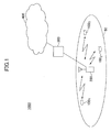
- FIG. 1 is a schematic diagram of a mobile communication system 1000.
- the mobile communication system 1000 includes a cell 50; user devices (user equipment: UE) 100 1 , 100 2 , and 100 3 (may also be called the user device 100 and the user devices 100); a base station 200 wirelessly communicating with the user devices 100, an upper node 300 connected to the base station 200, and a core network 400 connected to the upper node 300.
- the upper node 300 is, for example, a radio network controller (RNC), an access gateway (aGW), or a mobility management entity (MME).
- RNC radio network controller
- aGW access gateway
- MME mobility management entity
- a multicarrier scheme is used for both uplink and downlink.
- OFDM may be used in an area where radio propagation conditions are good (e.g., an area near a base station), and a single-carrier scheme (SC-FDMA) may be used in an area where radio propagation conditions are poor (e.g., an area near the cell edge).
- SC-FDMA single-carrier scheme
- control information includes uplink L1/L2 control information, acknowledgement/negative-acknowledgement information (ACK/NACK) for a data channel transmitted via downlink, and/or a channel quality indicator (CQI) indicating downlink channel conditions.
- the control information may include any other appropriate information.
- control information transmission methods according to an embodiment of the present invention are described.
- the control information transmission methods described below are examples and do not encompass the entire scope of the present invention.
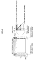
- FIG. 2 is a drawing illustrating a control information transmission method (1).
- two narrow frequency bands are provided at the right and left ends of a system frequency band including multiple (frequency) resource blocks.
- the system frequency band for example, has a bandwidth of 5 MHz, 10 MHz, or 20 MHz.
- the two frequency bands at the right and left ends are reserved for transmission of control information.
- the frequency band at the low frequency end is called a first control frequency band and the frequency band at the high frequency end is called a second control frequency band.
- one resource block has a bandwidth of about 180 kHz
- each of the first and second control frequency bands has a bandwidth corresponding to the bandwidth of one resource block.
- the system frequency band includes 25 resource blocks (#1-#25), a first resource block #1 corresponds to the first control frequency band, and a twenty-fifth resource block #25 corresponds to the second control frequency band.
- One radio frame for example, includes a predetermined number (e.g., 10) of 1-ms subframes. Each subframe includes, for example, two 0.5-ms slots.
- the system frequency band is also called a basic frequency band and the entire frequency band may include one or more basic frequency bands.
- control information is transmitted from user A to the base station in first and second slots that are consecutive.
- the first control frequency band is used in the first slot and the second control frequency band is used in the second slot.
- control information is transmitted according to a frequency hopping pattern using frequency bands that are widely apart from each other in the system bandwidth.
- This method makes it possible to achieve a high frequency diversity gain and is therefore preferable to improve the reception quality of control information.
- frequency hopping is performed by changing frequency bands every slot. However, frequency bands may be changed less frequently (e.g., every subframe) or more frequently (e.g., every symbol in a slot).
- this method may also be applied to a system employing a single-carrier scheme.
- one subframe corresponds to one TTI. However, this is not essential for the present invention.
- FIG. 3 is a drawing illustrating a control information transmission method (2).
- control information is transmitted from user A to the base station using the first and second control frequency bands.
- the first and second control frequency bands are used at the same.
- This method is applicable only to a system employing a multicarrier scheme. Since the first and second control frequency bands are used throughout the subframe (or two slots), this method provides transmission capacity greater than that provided by the method of FIG. 2 .
- This method is preferable when the number of symbols or bits of control information of each user is large, when the number of multiplexed users is large, or when the radio propagation conditions are poor.
- the method (2) is preferable when the radio propagation conditions are poor.
- either OFDM or DFT-spread OFDM may be used for communications based on a multicarrier scheme.
- a single-carrier scheme is more preferable than a multicarrier scheme in terms of reducing the peak power.
- DFT-spread OFDM is more preferable than OFDM in terms of reducing the peak power. This is due to the difference in the number of subcarriers.
- FIG. 4 is a drawing illustrating a control information transmission method (3).
- control information is transmitted according to OFDM.
- the first and second control frequency bands are used by one or more user devices. Any known multiplexing method may be used to multiplex users. In this embodiment, frequency division multiple access (FDMA), code division multiple access (CDMA), or time division multiple access (TDMA) is used to multiplex users.
- FDMA frequency division multiple access
- CDMA code division multiple access
- TDMA time division multiple access
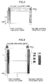
- FIG. 5 is a drawing illustrating a control information transmission method (4) : FDMA.
- FIG. 6 is a drawing illustrating a control information transmission method (5): CDMA.
- control information of each user is spread by a unique spreading code and mapped to all subcarriers in the first and second control frequency bands. Spreading may be performed only in the frequency or time direction or both in the frequency and time directions.
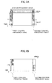
- FIG. 7A is a drawing illustrating a control information transmission method (6): TDMA.
- TDMA control information transmission method
- one subframe is divided into first and second slots, and different sets of information are transmitted in the first slot and the second slot in each of the first and second control frequency bands.
- Control information of each user is mapped to a time period allocated by TDMA and transmitted.
- One subframe may also be divided by TDMA into any appropriate time periods other than slots. For example, as shown in FIG. 8 , one subframe may be divided into time periods corresponding to OFDM symbols.
- FIG. 7B is a drawing illustrating a combination of TDMA and FDMA. As shown in FIG. 7B , one subframe is divided into first and second slots, and different sets of information are transmitted in the first slot and the second slot in each of the first and second control frequency bands. In this method, FDMA is also applied to each slot. Although each of the first and second control frequency bands is divided into two frequency bands in FIG. 7B , the first and second control frequency bands may be divided into any number of frequency bands.
- FIG. 9 is a drawing illustrating a control information transmission method (8).
- control information is transmitted using DFT-spread OFDM.
- DFT-spread OFDM a signal before transmission is discrete-Fourier-transformed, the transformed signal is mapped to one or more frequency ranges in the frequency domain, and the mapped signal is inverse-Fourier-transformed for transmission.
- DFT-spread OFDM both a single-carrier signal and a multicarrier signal can be generated.
- DFT-spread OFDM is performed such that a control signal is mapped to both of the first and second control frequency bands. Let us assume that each of the first and second control frequency bands corresponds to one resource block, and one resource block has a bandwidth of 180 kHz.
- both of the first and second control frequency bands are used to transmit control information of a user, but a single-carrier scheme is used in each of the first and second control frequency bands. More specifically, control information of one user is transmitted using two subcarriers. That is, two single-carrier signals are transmitted in parallel. In terms of reducing the peak-to-average power ratio (PAPR), this method is more preferable than the method of FIG. 4 where a multicarrier signal is generated as a prerequisite.
- PAPR peak-to-average power ratio
- the first and second control frequency bands are used by one or more user devices. Any known multiplexing method may be used to multiplex users. In this embodiment, code division multiple access (CDMA) or time division multiple access (TDMA) is used to multiplex users.
- CDMA code division multiple access
- TDMA time division multiple access
- FIG. 10 is a drawing illustrating a control information transmission method (9): CDMA.
- control information of each user is spread by a unique spreading code and mapped to the first and second control frequency bands.
- the method of FIG. 10 is different from the method of FIG. 6 in that a single carrier scheme is used to transmit control information in each of the first and second control frequency bands.
- FIG. 11 is a drawing illustrating a control information transmission method (10).
- sets of control information of different users are code-division-multiplexed.
- sets of control information of the same user are code-division multiplexed.
- ACK/NACK and a CQI of the same user are code-division-multiplexed for transmission.
- FIG. 12 is a drawing illustrating a control information transmission method (11). Also in this method, sets of control information of different users are code-division-multiplexed.
- a system e.g., an LTE system
- LTE-A LTE-advanced
- Control information is transmitted by a single carrier scheme in each of the first and second control frequency bands.
- FIG. 13 is a drawing illustrating a control information transmission method (12): TDMA.
- TDMA control information transmission method
- one subframe is divided into first and second slots, and different sets of information are transmitted in the first slot and the second slot.
- Control information of each user is mapped to a time period allocated by TDMA and is transmitted.
- the subframe may be divided by TDMA not only into slots but into any other appropriate time periods. For example, as shown in FIG. 8 , one subframe may be divided into time periods corresponding to OFDM symbols. However, it is preferable to transmit control information of each user within a continuous short time period (one half of TTI, i.e., one slot) as shown in FIG. 13 in order to reduce delay for the user.
- FIG. 14 is a drawing illustrating a control information transmission method (13).
- LTE-A users are code-division-multiplexed.
- LTE-A users are time-division-multiplexed.
- LTE users and LTE-A users are code-division-multiplexed in a manner similar to FIG. 12 .
- This method is preferable to improve the compatibility (backward compatibility) of a new system with an old system as well as to reduce delay for LTE-A users.
- Uplink control information may be transmitted separately from a data channel or together with a data channel.
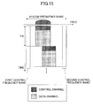
- FIG. 15 is a drawing illustrating a control information transmission method (14).
- a data channel is mapped to a continuous frequency band according to DFT-spread OFDM and transmitted via uplink. This corresponds to a case where a data channel is transmitted using one or more adjacent resource blocks in an LTE system.
- control information is also transmitted using the resource blocks of the data channel. Since the resource blocks are consecutive, a single-carrier method can be used for transmission.
- FIG. 16 is a drawing illustrating a control information transmission method (15). Also in this method, control information is transmitted using the resource blocks of a data channel and the data channel is mapped to frequency bands according to DFT-spread OFDM. In this method, however, the data channel is not mapped to a continuous frequency band, but mapped to multiple frequency bands that are not continuous in the frequency domain. In this case, the single-carrier scheme cannot be used for transmission and at least two subcarriers are necessary for transmission (i.e., one or more subcarriers are necessary for each continuous frequency band).
- FIG. 17 is a drawing illustrating a control information transmission method (16). Also in this method, control information is transmitted using the resource blocks of a data channel. In this method, however, the data channel is transmitted according to OFDM. Therefore, the data channel is transmitted using various subcarriers in the system frequency band.
- FIG. 18 is a drawing illustrating a control information transmission method (17).
- control information is transmitted using the first and second control frequency bands and a data channel is transmitted using other frequency bands according to OFDM.
- control information is transmitted according to OFDM.
- FIG. 19 is a drawing illustrating a control information transmission method (18). Also in this method, control information is transmitted using the first and second control frequency bands and a data channel is transmitted using other frequency bands according to OFDM. Similarly to FIG. 9 , control information is transmitted according to DFT-spread OFDM.
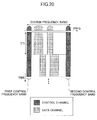
- FIG. 20 is a drawing illustrating a control information transmission method (19). Also in this method, control information is transmitted using the first and second control frequency bands. Similarly to FIG. 15 , a data channel is transmitted using other frequency bands according to DFT-spread OFDM. Also, similarly to FIG. 9 , control information is transmitted according to DFT-spread OFDM.
- FIG. 21 is a drawing illustrating an exemplary configuration of a control channel.
- one subframe (TTI) of 1 ms is divided into two slots of 0.5 ms, and each slot includes seven OFDM symbols.
- two of the seven OFDM symbols are used for a pilot channel (reference signal). Accordingly, the remaining five OFDM symbols can be used to transmit information other than the pilot channel.
- the length of a subframe, the number of slots, and the number of OFDM symbols may be changed as necessary.
- each of the five OFDM symbols of user UE_A includes the same CAZAC code sequence CAZAC1.
- the CAZAC code sequence CAZAC1 for example, has a sequence length of 12.
- Code sequences obtained by cyclically shifting the CAZAC code sequence CAZAC1 are also CAZAC code sequences and are orthogonal to each other. In the example of FIG. 21 , the above characteristics of CAZAC code sequences are used.
- An orthogonal code sequence used for another user UE_B is obtained by cyclically shifting the CAZAC code sequence CAZAC1 used for user UE A by a shift amount .
- the entire CAZAC code sequence CAZAC1 may be multiplied by the same factor.
- Modulation data A1 through modulation data A5 for user UE_A are prepared.
- the entire CAZAC code sequence CAZAC1 in a first OFDM symbol is multiplied by the modulation data A1.
- the entire CAZAC code sequence CAZAC1 in each of second through fifth OFDM symbols is multiplied by a corresponding one of the modulation data A2 through A5.
- the modulation data A1 through A5 may be different from each other, or two or more of them may be the same.
- the modulation data for example, represent the acknowledgement/negative-acknowledgement (ACK/NACK) information for a downlink data channel.
- the modulation data may represent a downlink channel quality indicator (CQI) measured based on a downlink pilot channel (downlink reference signal).
- CQI downlink channel quality indicator
- up to five sets of information can be transmitted for each user in one slot, and users are code-division-multiplexed using spreading codes with a sequence length of 12.
- FIG. 22 is a drawing illustrating an exemplary configuration of a control channel.
- the length of a subframe, the number of slots, and the number of OFDM symbols are based on the same assumption as in FIG. 21 and may be changed as necessary.
- the 12 symbol elements correspond to the sequence elements of the CAZAC code sequence.
- 12 symbol elements SA in an OFDM symbol of user UE_A represent control information of user UE_A.
- Each of the five OFDM symbols of user UE_A includes 12 symbol elements SA.
- the five OFDM symbols are multiplied, respectively, by spreading codes CA1 through CA5 with a sequence length of 5.
- 12 symbol elements SB in an OFDM symbol of user UE_B represent control information of user UE_B.
- Each of the five OFDM symbols of user UE_B includes 12 symbol elements SB.
- the five OFDM symbols are multiplied, respectively, by spreading codes CB1 through CB5 with a sequence length of 5.
- up to 12 sets of information can be transmitted for each user in one slot, and users are code-division-multiplexed using spreading codes with a sequence length of 5. This method makes it possible to transmit a larger amount of information for each user.
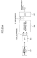
- FIG. 23A is a partial functional block diagram of an exemplary user device.
- the user device includes a signal generating unit 231, a discrete Fourier transform unit (DFT) 233, a subcarrier mapping unit 235, and an inverse fast Fourier transform unit (IFFT) 237.
- DFT discrete Fourier transform unit
- IFFT inverse fast Fourier transform unit
- the signal generating unit 231 generates a sequence for a transmission signal. This sequence is in the time domain.
- the signal generating unit 231 may be configured to generate any appropriate transmission signal. In a certain situation where a predetermined signal is to be transmitted, the signal generating.unit 231 generates a signal sequence representing a CQI indicating a downlink reception level or quality even if the uplink shared data channel is not allocated to the user device.
- the signal generating unit 231 When acknowledgement/negative-acknowledgement information for a downlink shared data channel received via downlink is generated, the signal generating unit 231 generates a signal sequence representing the acknowledgement/negative-acknowledgement information.
- the acknowledgement/negative-acknowledgement information indicates either acknowledgement (ACK) or negative acknowledgement (NACK).
- the discrete Fourier transform unit (DFT) 233 discrete-Fourier-transforms the time-domain signal sequence received from the signal generating unit 231 and thereby generates a frequency-domain signal sequence.
- DFT discrete Fourier transform unit
- the subcarrier mapping unit 235 maps the frequency-domain signal sequence to a frequency band(s) (subcarrier(s)) available for uplink. Normally, the subcarrier mapping unit 235 maps the signal sequence to one or both of the first and second control frequency bands provided at the corresponding ends of the system frequency band. When a single-carrier scheme is used for uplink, the signal is mapped so as to occupy one continuous frequency band at any moment.
- the inverse fast Fourier transform unit (IFFT) 237 inverse-fast-Fourier-transforms the mapped signal and thereby transforms the signal into a time-domain signal. Then, the time-domain signal is transmitted via a radio transmission unit (not shown).
- IFFT inverse fast Fourier transform unit
- FIG. 23B is a partial functional block diagram of another exemplary user device.
- a signal generating unit 232 generates a transmission signal in the frequency domain. Therefore, the signal generated by the signal generating unit 232 is simply converted from serial to parallel by a serial-parallel conversion unit (S/P) 234 and input to a subcarrier mapping unit 236.
- S/P serial-parallel conversion unit
- the subcarrier mapping unit 236 and an inverse fast Fourier transform unit (IFFT) 238 have substantially the same functions as the corresponding components shown in FIG. 23A , and therefore their descriptions are omitted here.
- IFFT inverse fast Fourier transform unit
- the subcarrier mapping unit 235,236 is configured to map a signal such that discontinuous frequency bands are not used at the same time. Therefore, the signal (control signal) can be transmitted using a single-carrier scheme. Accordingly, the user devices of FIGs. 23A and 23B can be used for a system where, for example, one of the transmission methods of FIGs. 2 , 7B , 11 , and 15 is employed.
- FIG. 24A is a partial functional block diagram of an exemplary user device that can use both a single-carrier scheme and a multicarrier scheme to transmit a signal.
- the user device includes a signal generating unit 241, a serial-parallel conversion unit (S/P) 243, a subcarrier mapping unit 245, and an inverse fast Fourier transform unit (IFFT) 247.
- S/P serial-parallel conversion unit
- IFFT inverse fast Fourier transform unit
- the signal generating unit 241 generates a signal sequence in the frequency domain.
- the serial-parallel conversion unit (S/P) 243 converts a serial signal sequence in the frequency domain into a parallel signal sequence.
- the sub-carrier mapping unit 245 maps the signal in the frequency domain to subcarriers.
- the user device of FIG. 24A is capable of transmitting an uplink signal using a multicarrier scheme.
- the multicarrier signal may be generated according to OFDM or DFT-spread OFDM.
- DFT-spread OFDM is employed, the user device of FIG. 24A is equivalent to the user devices of FIGS. 23A and 23B that can use a multicarrier scheme for uplink in addition to a single-carrier scheme.
- the inverse fast Fourier transform unit (IFFT) 247 inverse-fast-Fourier-transforms the mapped signal and thereby transforms the mapped signal into a time-domain signal. Then, the time-domain signal is transmitted via a radio transmission unit (not shown).
- IFFT inverse fast Fourier transform unit
- each of the first and second control frequency bands corresponds to one resource block that includes 12 subcarriers.
- FIG. 24B is a partial functional block diagram of still another exemplary user device.
- the user device of FIG. 24B is substantially the same as the user device of FIG. 24A except that a signal is generated for each resource block. Accordingly, radio transmission signals transmitted from the user devices of FIGs. 24A and 24B have similar waveforms.
- the user device of FIG. 24A can achieve higher code spreading gain and is therefore more preferable than the user device of FIG. 24B .
- the maximum spreading factor in the frequency direction is 24 (24 subcarriers.
- the maximum spreading factor in the frequency direction is 12 (12 subcarriers). This difference has particularly great significance when spreading is performed two-dimensionally both in the time and frequency directions.
- FIG. 25 is a functional block diagram of a base station.
- the base station includes a synchronization-detection-and-channel-estimation unit 251, a guard interval removing unit 252, a fast Fourier transform unit (FFT) 253, a subcarrier demapping unit 254, a data demodulation unit 255, a data decoding unit 256, and an ACK/NACK determining unit 257.
- FFT fast Fourier transform unit
- the synchronization-detection-and-channel-estimation unit 251 performs synchronization detection and channel estimation based on a pilot channel received via uplink.
- the guard interval removing unit 252 removes guard intervals from a received signal according to the synchronization timing of the received signal.
- the fast Fourier transform unit (FFT) 253 fast-Fourier-transforms the received signal and thereby transforms the received signal in the time domain into a signal in the frequency domain.
- the subcarrier demapping unit 254 extracts a signal mapped to subcarriers.
- the signal may include only a control channel or both a control channel and a data channel.
- the data demodulation unit 255 performs data demodulation on the received signal.
- the data decoding unit 256 performs data decoding on the data-demodulated signal.
- the data demodulation and the data decoding are performed for a control channel and a data channel separately. However, for brevity, those processes are represented collectively in FIG. 25 .
- the ACK/NACK determining unit 257 determines whether the uplink data channel has been properly received by, for example, performing error detection.
- the error detection may be performed by cyclic redundancy check (CRC).
- CRC cyclic redundancy check
- An embodiment of the present invention provides a user device for a mobile communication system employing a multicarrier scheme.
- the user device includes a control signal generating unit generating a control signal and a transmitting unit transmitting the control signal to a base station.
- the control signal is mapped to multiple frequency bands that are provided across a subframe but discontinuous in the frequency domain.
- Each of the frequency bands includes subcarriers used in orthogonal frequency division multiplexing (OFDM). This configuration makes it possible to transmit the control signal using OFDM and thereby makes it possible to transmit a large amount of information and/or highly accurate information at high speed.
- OFDM orthogonal frequency division multiplexing
- the control signal may be mapped to a subcarrier(s) allocated by frequency division multiple access (FDMA). This configuration makes it possible to accurately separate signals of multiple users.
- FDMA frequency division multiple access
- the control signal may be spread by a spreading code used in code division multiple access (CDMA). This configuration makes it possible to increase the number of multiplexed users.
- CDMA code division multiple access
- the control signal may be two-dimensionally spread both in the time domain and the frequency domain.
- the control signal may be transmitted in a time period allocated by time division multiple access (TDMA). This configuration makes it possible to accurately separate signals transmitted in different time periods.
- TDMA time division multiple access
- a subframe may include a predetermined number of pilot transmission periods for transmitting a pilot channel and a predetermined number of information transmission periods for transmitting information other than the pilot channel.
- a signal including an orthogonal code sequence with a sequence length corresponding to the length of each of the information transmission periods may be transmitted in each of the information transmission periods and the entire orthogonal code sequence may be multiplied by (the same) one factor. This configuration makes it possible to distinguish users by orthogonal codes and thereby to reduce interference between users.
- a subframe may include a first number of pilot transmission periods for transmitting a pilot channel and a second number of information transmission periods for transmitting information other than the pilot channel.
- a control signal may be transmitted in each of the second number of information transmission periods and the control signal may be multiplied by a spreading code having a sequence length that equals the second number.
- the user device further includes a data signal generating unit generating a data signal.
- the data signal is mapped to multiple frequency bands provided separately from the frequency bands for the control signal.
- the frequency bands for the data signal are provided across a subframe but discontinuous in the frequency domain.
- Each of the frequency bands for the data signal may include subcarriers used in OFDM. This configuration makes it possible to transmit the control signal using OFDM and thereby makes it possible to transmit a large amount of information and/or highly accurate information at high speed.
- An embodiment of the present invention provides a method performed by a user device for a mobile communication system employing a multicarrier scheme.
- the method includes a step of generating a control signal and a step of transmitting the control signal to a base station.
- the control signal is mapped to multiple frequency bands that are provided across a subframe but discontinuous in the frequency domain.
- Each of the frequency bands includes subcarriers used in orthogonal frequency division multiplexing (OFDM).
- An embodiment of the present invention provides a base station for a mobile communication system employing a multicarrier scheme.
- the base station includes a receiving unit receiving a control signal from at least one user device and a restoring unit restoring the received control signal to an original signal before transmission (a pre-transmission signal).
- the control signal from the user device is extracted from multiple frequency bands that are provided across a subframe but discontinuous in the frequency domain.
- Each of the frequency bands includes subcarriers used in orthogonal frequency division multiplexing (OFDM).
- the control signal may be despread by a spreading code used in code division multiple access (CDMA).
- CDMA code division multiple access
- the control signal may be transmitted in a time period allocated by time division multiple access (TDMA).
- TDMA time division multiple access
- the subframe may include a predetermined number of pilot transmission periods for transmitting a pilot channel and a predetermined number of information transmission periods for transmitting information other than the pilot channel.
- a signal including an orthogonal code sequence with a sequence length corresponding to the length of each of the information transmission periods may be received in each of the information transmission periods and the entire orthogonal code sequence may be multiplied by (the same) one factor.
- a subframe may include a first number of pilot transmission periods for transmitting a pilot channel and a second number of information transmission periods for transmitting information other than the pilot channel.
- a control signal may be received in each of the second number of information transmission periods and the control signal may be multiplied by a spreading code having a sequence length that equals the second number.
- the base station may also receive a data signal from the user device.
- the data signal is extracted from multiple frequency bands provided separately from the frequency bands for the control signal.
- the frequency bands for the data signal are provided' across a subframe but discontinuous in the frequency domain.
- Each of the frequency bands for the data signal may include subcarriers used in OFDM.
- An embodiment of the present invention provides a method performed by a base station for a mobile communication system employing a multicarrier scheme.
- the method includes a step of receiving a control signal from at least one user device and a step of restoring the received control signal to an original signal before transmission.
- the control signal from the user device is extracted from multiple frequency bands that are provided across a subframe but discontinuous in the frequency domain.
- Each of the frequency bands may include subcarriers used in orthogonal frequency division multiplexing (OFDM).
- the present invention may be applied to any appropriate mobile communication system where a multicarrier scheme is used for uplink.
- a mobile communication system employing a multicarrier scheme according to an embodiment of the present invention may be combined with any other appropriate mobile communication system.
- a mobile communication system according to an embodiment of the present invention may be used together with an HSDPA/HSUPA W-CDMA system, an LTE system, an IMT-Advanced system, a WiMAX system, or a Wi-Fi system.
Landscapes
- Engineering & Computer Science (AREA)
- Signal Processing (AREA)
- Computer Networks & Wireless Communication (AREA)
- Mobile Radio Communication Systems (AREA)
- Power Engineering (AREA)
Applications Claiming Priority (2)
| Application Number | Priority Date | Filing Date | Title |
|---|---|---|---|
| JP2008163843A JP5127588B2 (ja) | 2008-06-23 | 2008-06-23 | 移動通信システムにおけるユーザ装置、基地局装置及び通信方法 |
| PCT/JP2009/061128 WO2009157367A1 (fr) | 2008-06-23 | 2009-06-18 | Dispositif d'utilisateur, dispositif de station de base, et procédé de communication dans un système de communication mobile |
Publications (3)
| Publication Number | Publication Date |
|---|---|
| EP2293634A1 true EP2293634A1 (fr) | 2011-03-09 |
| EP2293634A4 EP2293634A4 (fr) | 2014-05-21 |
| EP2293634B1 EP2293634B1 (fr) | 2016-10-12 |
Family
ID=41444435
Family Applications (1)
| Application Number | Title | Priority Date | Filing Date |
|---|---|---|---|
| EP09770077.7A Not-in-force EP2293634B1 (fr) | 2008-06-23 | 2009-06-18 | Dispositif d'utilisateur, dispositif de station de base, et procédé de communication dans un système de communication mobile |
Country Status (9)
| Country | Link |
|---|---|
| US (1) | US9136996B2 (fr) |
| EP (1) | EP2293634B1 (fr) |
| JP (1) | JP5127588B2 (fr) |
| KR (1) | KR20110026446A (fr) |
| CN (1) | CN102124799B (fr) |
| AU (1) | AU2009263425B8 (fr) |
| BR (1) | BRPI0915716A2 (fr) |
| RU (1) | RU2507719C2 (fr) |
| WO (1) | WO2009157367A1 (fr) |
Families Citing this family (15)
| Publication number | Priority date | Publication date | Assignee | Title |
|---|---|---|---|---|
| KR101481507B1 (ko) * | 2007-03-12 | 2015-01-13 | 엘지전자 주식회사 | 부가 제어 신호 송수신 방법 |
| JP2011035785A (ja) * | 2009-08-04 | 2011-02-17 | Sharp Corp | 無線通信システム、移動局装置および基地局装置 |
| WO2011041623A1 (fr) * | 2009-10-01 | 2011-04-07 | Interdigital Patent Holdings, Inc. | Transmission de données de commande en liaison montante |
| EP2522095A2 (fr) | 2010-01-08 | 2012-11-14 | InterDigital Patent Holdings, Inc. | Transmission d'informations d'état de canal pour de multiples porteuses |
| US9843434B2 (en) * | 2012-08-05 | 2017-12-12 | Lg Electronics Inc. | Method of configuring cyclic prefix for small cell in wireless communication system and apparatus therefor |
| US9066362B2 (en) * | 2013-03-08 | 2015-06-23 | Qualcomm Incorporated | Prioritizing time critical data for transmission during power limited state in DC-HSUPA operation |
| US9930114B2 (en) * | 2014-10-28 | 2018-03-27 | Empire Technology Development Llc | Code-division-multiple-access (CDMA)-based network coding for massive memory servers |
| JP6878278B2 (ja) * | 2015-07-17 | 2021-05-26 | 株式会社Nttドコモ | 端末、無線通信方法、基地局及びシステム |
| US9391818B1 (en) * | 2015-09-17 | 2016-07-12 | National Instruments Corporation | Pilot sequence design for wireless communications |
| US10516510B2 (en) | 2015-11-11 | 2019-12-24 | Telefonaktiebolaget Lm Ericsson (Publ) | Method and apparatus for wireless communication |
| RU2741615C2 (ru) * | 2016-07-05 | 2021-01-27 | Нтт Докомо, Инк. | Пользовательский терминал и способ радиосвязи |
| JP2019169748A (ja) * | 2016-08-09 | 2019-10-03 | シャープ株式会社 | 端末装置、基地局装置、通信方法、および、集積回路 |
| JP2019208082A (ja) * | 2016-09-29 | 2019-12-05 | シャープ株式会社 | 端末装置、基地局装置、通信方法、および、集積回路 |
| US20200287688A1 (en) * | 2017-09-07 | 2020-09-10 | Ntt Docomo, Inc. | User terminal and radio communication method |
| US10911919B2 (en) * | 2018-12-24 | 2021-02-02 | Industrial Technology Research Institute | Wireless access method, wireless receiving method for a communication system and a base station therefor with a low-latency mechanism |
Family Cites Families (36)
| Publication number | Priority date | Publication date | Assignee | Title |
|---|---|---|---|---|
| DE60122259T2 (de) * | 2000-04-10 | 2006-12-07 | Samsung Electronics Co., Ltd., Suwon | Verfahren zur messung der verwirrungsrate eines gemeinsames paketkanals in einem cdma-übertragungssystem |
| KR100627188B1 (ko) * | 2000-07-04 | 2006-09-22 | 에스케이 텔레콤주식회사 | 무선통신 역방향 동기 방식에서의 코드 할당 방법 |
| KR100438447B1 (ko) * | 2000-10-20 | 2004-07-03 | 삼성전자주식회사 | 이동통신시스템에서 버스트 파일롯 송신장치 및 방법 |
| US7272110B2 (en) * | 2001-09-29 | 2007-09-18 | Lg Electronics Inc. | Method of allocating walsh code resource |
| KR100474719B1 (ko) * | 2001-11-30 | 2005-03-08 | 삼성전자주식회사 | 이동통신시스템에서 제어정보를 송수신하는 방법 및 장치 |
| US7039370B2 (en) * | 2003-10-16 | 2006-05-02 | Flarion Technologies, Inc. | Methods and apparatus of providing transmit and/or receive diversity with multiple antennas in wireless communication systems |
| US8526412B2 (en) * | 2003-10-24 | 2013-09-03 | Qualcomm Incorporated | Frequency division multiplexing of multiple data streams in a wireless multi-carrier communication system |
| US20070202904A1 (en) * | 2004-03-12 | 2007-08-30 | Matsushita Electric Industrial Co., Ltd. | Scheduling Method And Base Station Apparatus |
| JP2005286508A (ja) * | 2004-03-29 | 2005-10-13 | Toshiba Corp | 無線通信システムおよびこのシステムで用いられる送信装置、受信装置、送受信装置 |
| CA2562705A1 (fr) * | 2004-04-15 | 2005-11-17 | Qualcomm Flarion Technologies, Inc. | Procedes et appareils de communication multiporteuse |
| WO2005109709A1 (fr) | 2004-05-06 | 2005-11-17 | Matsushita Electric Industrial Co., Ltd. | Appareil transmetteur multiporteuse, appareil récepteur multiporteuse, méthode de transmission multiporteuse et méthode de réception multiporteuse |
| US7535821B2 (en) * | 2005-02-02 | 2009-05-19 | Electronics And Telecommunications Research Institute | Method for generating two-dimensional orthogonal variable spreading code and MIMO system using the same |
| KR100896280B1 (ko) * | 2005-03-30 | 2009-05-08 | 엘지전자 주식회사 | 광대역 무선접속 시스템의 상향링크 구간 할당 정보 송수신방법 |
| EP1869825B1 (fr) * | 2005-03-30 | 2017-08-23 | LG Electronics Inc. | Procede de transmission et de reception d'informations d'attribution de region de liaison montante dans un systeme d'acces sans fil a bande large |
| WO2007069848A2 (fr) * | 2005-12-13 | 2007-06-21 | Lg Electronics Inc. | Procédé de communication utilisant une station-relais dans un système de communication mobile |
| JP4740778B2 (ja) * | 2006-03-27 | 2011-08-03 | 富士通東芝モバイルコミュニケーションズ株式会社 | Ofdm無線通信システムおよび送信装置、受信装置 |
| JP2007274094A (ja) * | 2006-03-30 | 2007-10-18 | Toshiba Corp | 基地局、無線端末および無線通信方法 |
| CN106899398B (zh) * | 2006-10-02 | 2020-10-23 | Lg电子株式会社 | 传输下行链路控制信号的方法 |
| JP4976498B2 (ja) * | 2006-10-02 | 2012-07-18 | エルジー エレクトロニクス インコーポレイティド | 効率的な多重化を用いた制御信号送信方法 |
| KR100910707B1 (ko) | 2006-10-19 | 2009-08-04 | 엘지전자 주식회사 | 제어신호 전송 방법 |
| JPWO2008050574A1 (ja) * | 2006-10-23 | 2010-02-25 | シャープ株式会社 | 移動体通信システム、移動体通信方法、基地局装置および移動局装置 |
| GB2443460B (en) * | 2006-10-31 | 2009-04-01 | Motorola Inc | Method and apparatus for use in wireless communications |
| JP4869889B2 (ja) * | 2006-11-29 | 2012-02-08 | 京セラ株式会社 | 基地局装置及び通信方法 |
| CN101574007A (zh) * | 2006-12-28 | 2009-11-04 | 诺基亚公司 | 电路交换呼叫到分组交换呼叫以及分组交换呼叫到电路交换呼叫的切换 |
| JP4970928B2 (ja) | 2006-12-28 | 2012-07-11 | 日立オートモティブシステムズ株式会社 | ドライヤ付き空気圧縮装置 |
| CN104052566B (zh) * | 2007-01-05 | 2017-06-16 | 三星电子株式会社 | 单载波频分多址系统中发送和接收控制信息的方法和装置 |
| US8223854B2 (en) * | 2007-01-10 | 2012-07-17 | Motorola Mobility, Inc. | Method and apparatus for transmission of uplink control signaling and user data in a single carrier orthogonal frequency division multiplexing communication system |
| US8369299B2 (en) * | 2007-05-07 | 2013-02-05 | Qualcomm Incorporated | Method and apparatus for multiplexing CDM pilot and FDM data |
| KR100956494B1 (ko) * | 2007-06-14 | 2010-05-07 | 엘지전자 주식회사 | 제어신호 전송 방법 |
| US8681737B2 (en) * | 2007-09-21 | 2014-03-25 | Motorola Mobility Llc | Method and apparatus for inter-technology handoff between a packet data network and a circuit switched network |
| US8493873B2 (en) * | 2007-06-18 | 2013-07-23 | Qualcomm Incorporated | Multiplexing of sounding signals in ACK and CQI channels |
| US8879565B2 (en) * | 2007-08-20 | 2014-11-04 | Motorola Mobility Llc | Method of updating core domain information for routing a service, communication device, and communication environment |
| CN101227677B (zh) * | 2008-02-05 | 2011-06-22 | 中兴通讯股份有限公司 | 一种单无线信道语音业务连续性的域切换方法 |
| EP2351395A4 (fr) * | 2008-11-03 | 2014-07-09 | Nokia Corp | Procédé, appareil et produit programme informatique permettant de sécuriser un transfert entre un réseau à commutation de paquets et un réseau à commutation de circuits |
| CA2760834C (fr) * | 2009-05-04 | 2015-11-24 | Research In Motion Limited | Systeme et methode de communication par information de technologie d'acces radio aux stations mobiles |
| EP2391177B1 (fr) * | 2010-05-25 | 2014-04-30 | HTC Corporation | Appareils, systèmes et procédés de gestion des procédures de détachement à l'expiration d'abonnement d'un groupe d'abonnés fermé |
-
2008
- 2008-06-23 JP JP2008163843A patent/JP5127588B2/ja not_active Expired - Fee Related
-
2009
- 2009-06-18 CN CN200980132075.2A patent/CN102124799B/zh not_active Expired - Fee Related
- 2009-06-18 EP EP09770077.7A patent/EP2293634B1/fr not_active Not-in-force
- 2009-06-18 BR BRPI0915716A patent/BRPI0915716A2/pt not_active IP Right Cessation
- 2009-06-18 KR KR20107029809A patent/KR20110026446A/ko not_active Ceased
- 2009-06-18 WO PCT/JP2009/061128 patent/WO2009157367A1/fr not_active Ceased
- 2009-06-18 AU AU2009263425A patent/AU2009263425B8/en not_active Ceased
- 2009-06-18 US US12/996,995 patent/US9136996B2/en not_active Expired - Fee Related
- 2009-06-18 RU RU2011101442/07A patent/RU2507719C2/ru not_active IP Right Cessation
Also Published As
| Publication number | Publication date |
|---|---|
| EP2293634B1 (fr) | 2016-10-12 |
| BRPI0915716A2 (pt) | 2015-10-27 |
| JP2010004499A (ja) | 2010-01-07 |
| RU2507719C2 (ru) | 2014-02-20 |
| KR20110026446A (ko) | 2011-03-15 |
| CN102124799A (zh) | 2011-07-13 |
| WO2009157367A1 (fr) | 2009-12-30 |
| EP2293634A4 (fr) | 2014-05-21 |
| AU2009263425B8 (en) | 2014-02-27 |
| CN102124799B (zh) | 2014-04-23 |
| AU2009263425A1 (en) | 2009-12-30 |
| RU2011101442A (ru) | 2012-07-27 |
| JP5127588B2 (ja) | 2013-01-23 |
| US20110188467A1 (en) | 2011-08-04 |
| US9136996B2 (en) | 2015-09-15 |
| AU2009263425B2 (en) | 2014-01-09 |
Similar Documents
| Publication | Publication Date | Title |
|---|---|---|
| EP2293634B1 (fr) | Dispositif d'utilisateur, dispositif de station de base, et procédé de communication dans un système de communication mobile | |
| EP2140581B1 (fr) | Procédé d'émission d'un signal de référence dans un système de communication sans fil | |
| JP5752783B2 (ja) | マルチ−セルtdd通信システムにおける応答信号の送信に対するリソースインデクシング | |
| US8228936B2 (en) | Method for multiplexing control signals and reference signals in mobile communications system | |
| KR101673906B1 (ko) | Ofdm 시스템에서 공간 다중화 제어 채널 지원을 위한 상향 링크 ack/nack 채널의 맵핑 방법 및 장치 | |
| JP5068699B2 (ja) | 基地局装置及び方法 | |
| JP5097793B2 (ja) | 基地局装置、移動端末装置および通信制御方法 | |
| EP2015488A1 (fr) | Emetteur et recepteur | |
| EP2487978A1 (fr) | Procédé de commande de communication sans fil, dispositif terminal mobile et dispositif de station de base | |
| CN102007724B (zh) | 移动通信系统、发送装置、接收装置及方法 | |
| EP2330855A1 (fr) | Dispositif terminal mobile, dispositif de station de base et procédé de transmission de signal de canal commun | |
| CN104272617B (zh) | 无线通信系统、移动终端装置、无线基站装置及无线通信方法 | |
| EP2608597A1 (fr) | Appareil pour station de base, appareil pour terminal mobile et procédé de commande de communication | |
| US20130064200A1 (en) | Base station apparatus, mobile terminal apparatus and communication control method | |
| KR20090062737A (ko) | 무선자원 맵핑 방법 및 이를 이용한 송신기 | |
| JP5249454B2 (ja) | ユーザ装置 | |
| JP5280573B2 (ja) | 無線通信システム、通信制御方法、基地局装置及び移動端末装置 |
Legal Events
| Date | Code | Title | Description |
|---|---|---|---|
| PUAI | Public reference made under article 153(3) epc to a published international application that has entered the european phase |
Free format text: ORIGINAL CODE: 0009012 |
|
| 17P | Request for examination filed |
Effective date: 20110105 |
|
| AK | Designated contracting states |
Kind code of ref document: A1 Designated state(s): AT BE BG CH CY CZ DE DK EE ES FI FR GB GR HR HU IE IS IT LI LT LU LV MC MK MT NL NO PL PT RO SE SI SK TR |
|
| AX | Request for extension of the european patent |
Extension state: AL BA RS |
|
| DAX | Request for extension of the european patent (deleted) | ||
| A4 | Supplementary search report drawn up and despatched |
Effective date: 20140425 |
|
| RIC1 | Information provided on ipc code assigned before grant |
Ipc: H04L 5/00 20060101ALI20140417BHEP Ipc: H04B 1/707 20110101ALI20140417BHEP Ipc: H04W 72/04 20090101AFI20140417BHEP Ipc: H04J 11/00 20060101ALI20140417BHEP Ipc: H04J 13/00 20110101ALI20140417BHEP |
|
| 17Q | First examination report despatched |
Effective date: 20150326 |
|
| GRAP | Despatch of communication of intention to grant a patent |
Free format text: ORIGINAL CODE: EPIDOSNIGR1 |
|
| INTG | Intention to grant announced |
Effective date: 20160504 |
|
| GRAS | Grant fee paid |
Free format text: ORIGINAL CODE: EPIDOSNIGR3 |
|
| GRAA | (expected) grant |
Free format text: ORIGINAL CODE: 0009210 |
|
| AK | Designated contracting states |
Kind code of ref document: B1 Designated state(s): AT BE BG CH CY CZ DE DK EE ES FI FR GB GR HR HU IE IS IT LI LT LU LV MC MK MT NL NO PL PT RO SE SI SK TR |
|
| REG | Reference to a national code |
Ref country code: GB Ref legal event code: FG4D |
|
| REG | Reference to a national code |
Ref country code: CH Ref legal event code: EP |
|
| REG | Reference to a national code |
Ref country code: AT Ref legal event code: REF Ref document number: 837469 Country of ref document: AT Kind code of ref document: T Effective date: 20161015 |
|
| REG | Reference to a national code |
Ref country code: IE Ref legal event code: FG4D |
|
| REG | Reference to a national code |
Ref country code: DE Ref legal event code: R096 Ref document number: 602009041702 Country of ref document: DE |
|
| REG | Reference to a national code |
Ref country code: LT Ref legal event code: MG4D |
|
| REG | Reference to a national code |
Ref country code: NL Ref legal event code: MP Effective date: 20161012 |
|
| PG25 | Lapsed in a contracting state [announced via postgrant information from national office to epo] |
Ref country code: LV Free format text: LAPSE BECAUSE OF FAILURE TO SUBMIT A TRANSLATION OF THE DESCRIPTION OR TO PAY THE FEE WITHIN THE PRESCRIBED TIME-LIMIT Effective date: 20161012 |
|
| REG | Reference to a national code |
Ref country code: AT Ref legal event code: MK05 Ref document number: 837469 Country of ref document: AT Kind code of ref document: T Effective date: 20161012 |
|
| PG25 | Lapsed in a contracting state [announced via postgrant information from national office to epo] |
Ref country code: NO Free format text: LAPSE BECAUSE OF FAILURE TO SUBMIT A TRANSLATION OF THE DESCRIPTION OR TO PAY THE FEE WITHIN THE PRESCRIBED TIME-LIMIT Effective date: 20170112 Ref country code: LT Free format text: LAPSE BECAUSE OF FAILURE TO SUBMIT A TRANSLATION OF THE DESCRIPTION OR TO PAY THE FEE WITHIN THE PRESCRIBED TIME-LIMIT Effective date: 20161012 Ref country code: GR Free format text: LAPSE BECAUSE OF FAILURE TO SUBMIT A TRANSLATION OF THE DESCRIPTION OR TO PAY THE FEE WITHIN THE PRESCRIBED TIME-LIMIT Effective date: 20170113 Ref country code: SE Free format text: LAPSE BECAUSE OF FAILURE TO SUBMIT A TRANSLATION OF THE DESCRIPTION OR TO PAY THE FEE WITHIN THE PRESCRIBED TIME-LIMIT Effective date: 20161012 |
|
| PG25 | Lapsed in a contracting state [announced via postgrant information from national office to epo] |
Ref country code: PT Free format text: LAPSE BECAUSE OF FAILURE TO SUBMIT A TRANSLATION OF THE DESCRIPTION OR TO PAY THE FEE WITHIN THE PRESCRIBED TIME-LIMIT Effective date: 20170213 Ref country code: NL Free format text: LAPSE BECAUSE OF FAILURE TO SUBMIT A TRANSLATION OF THE DESCRIPTION OR TO PAY THE FEE WITHIN THE PRESCRIBED TIME-LIMIT Effective date: 20161012 Ref country code: PL Free format text: LAPSE BECAUSE OF FAILURE TO SUBMIT A TRANSLATION OF THE DESCRIPTION OR TO PAY THE FEE WITHIN THE PRESCRIBED TIME-LIMIT Effective date: 20161012 Ref country code: AT Free format text: LAPSE BECAUSE OF FAILURE TO SUBMIT A TRANSLATION OF THE DESCRIPTION OR TO PAY THE FEE WITHIN THE PRESCRIBED TIME-LIMIT Effective date: 20161012 Ref country code: BE Free format text: LAPSE BECAUSE OF FAILURE TO SUBMIT A TRANSLATION OF THE DESCRIPTION OR TO PAY THE FEE WITHIN THE PRESCRIBED TIME-LIMIT Effective date: 20161012 Ref country code: HR Free format text: LAPSE BECAUSE OF FAILURE TO SUBMIT A TRANSLATION OF THE DESCRIPTION OR TO PAY THE FEE WITHIN THE PRESCRIBED TIME-LIMIT Effective date: 20161012 Ref country code: ES Free format text: LAPSE BECAUSE OF FAILURE TO SUBMIT A TRANSLATION OF THE DESCRIPTION OR TO PAY THE FEE WITHIN THE PRESCRIBED TIME-LIMIT Effective date: 20161012 Ref country code: IS Free format text: LAPSE BECAUSE OF FAILURE TO SUBMIT A TRANSLATION OF THE DESCRIPTION OR TO PAY THE FEE WITHIN THE PRESCRIBED TIME-LIMIT Effective date: 20170212 Ref country code: FI Free format text: LAPSE BECAUSE OF FAILURE TO SUBMIT A TRANSLATION OF THE DESCRIPTION OR TO PAY THE FEE WITHIN THE PRESCRIBED TIME-LIMIT Effective date: 20161012 |
|
| REG | Reference to a national code |
Ref country code: DE Ref legal event code: R097 Ref document number: 602009041702 Country of ref document: DE |
|
| PG25 | Lapsed in a contracting state [announced via postgrant information from national office to epo] |
Ref country code: RO Free format text: LAPSE BECAUSE OF FAILURE TO SUBMIT A TRANSLATION OF THE DESCRIPTION OR TO PAY THE FEE WITHIN THE PRESCRIBED TIME-LIMIT Effective date: 20161012 Ref country code: CZ Free format text: LAPSE BECAUSE OF FAILURE TO SUBMIT A TRANSLATION OF THE DESCRIPTION OR TO PAY THE FEE WITHIN THE PRESCRIBED TIME-LIMIT Effective date: 20161012 Ref country code: SK Free format text: LAPSE BECAUSE OF FAILURE TO SUBMIT A TRANSLATION OF THE DESCRIPTION OR TO PAY THE FEE WITHIN THE PRESCRIBED TIME-LIMIT Effective date: 20161012 Ref country code: DK Free format text: LAPSE BECAUSE OF FAILURE TO SUBMIT A TRANSLATION OF THE DESCRIPTION OR TO PAY THE FEE WITHIN THE PRESCRIBED TIME-LIMIT Effective date: 20161012 Ref country code: EE Free format text: LAPSE BECAUSE OF FAILURE TO SUBMIT A TRANSLATION OF THE DESCRIPTION OR TO PAY THE FEE WITHIN THE PRESCRIBED TIME-LIMIT Effective date: 20161012 |
|
| PLBE | No opposition filed within time limit |
Free format text: ORIGINAL CODE: 0009261 |
|
| STAA | Information on the status of an ep patent application or granted ep patent |
Free format text: STATUS: NO OPPOSITION FILED WITHIN TIME LIMIT |
|
| PG25 | Lapsed in a contracting state [announced via postgrant information from national office to epo] |
Ref country code: IT Free format text: LAPSE BECAUSE OF FAILURE TO SUBMIT A TRANSLATION OF THE DESCRIPTION OR TO PAY THE FEE WITHIN THE PRESCRIBED TIME-LIMIT Effective date: 20161012 Ref country code: BG Free format text: LAPSE BECAUSE OF FAILURE TO SUBMIT A TRANSLATION OF THE DESCRIPTION OR TO PAY THE FEE WITHIN THE PRESCRIBED TIME-LIMIT Effective date: 20170112 |
|
| 26N | No opposition filed |
Effective date: 20170713 |
|
| PG25 | Lapsed in a contracting state [announced via postgrant information from national office to epo] |
Ref country code: SI Free format text: LAPSE BECAUSE OF FAILURE TO SUBMIT A TRANSLATION OF THE DESCRIPTION OR TO PAY THE FEE WITHIN THE PRESCRIBED TIME-LIMIT Effective date: 20161012 |
|
| PG25 | Lapsed in a contracting state [announced via postgrant information from national office to epo] |
Ref country code: MC Free format text: LAPSE BECAUSE OF FAILURE TO SUBMIT A TRANSLATION OF THE DESCRIPTION OR TO PAY THE FEE WITHIN THE PRESCRIBED TIME-LIMIT Effective date: 20161012 |
|
| REG | Reference to a national code |
Ref country code: CH Ref legal event code: PL |
|
| GBPC | Gb: european patent ceased through non-payment of renewal fee |
Effective date: 20170618 |
|
| REG | Reference to a national code |
Ref country code: IE Ref legal event code: MM4A |
|
| REG | Reference to a national code |
Ref country code: FR Ref legal event code: ST Effective date: 20180228 |
|
| PG25 | Lapsed in a contracting state [announced via postgrant information from national office to epo] |
Ref country code: IE Free format text: LAPSE BECAUSE OF NON-PAYMENT OF DUE FEES Effective date: 20170618 Ref country code: CH Free format text: LAPSE BECAUSE OF NON-PAYMENT OF DUE FEES Effective date: 20170630 Ref country code: LU Free format text: LAPSE BECAUSE OF NON-PAYMENT OF DUE FEES Effective date: 20170618 Ref country code: LI Free format text: LAPSE BECAUSE OF NON-PAYMENT OF DUE FEES Effective date: 20170630 Ref country code: GB Free format text: LAPSE BECAUSE OF NON-PAYMENT OF DUE FEES Effective date: 20170618 |
|
| PG25 | Lapsed in a contracting state [announced via postgrant information from national office to epo] |
Ref country code: FR Free format text: LAPSE BECAUSE OF NON-PAYMENT OF DUE FEES Effective date: 20170630 |
|
| PGFP | Annual fee paid to national office [announced via postgrant information from national office to epo] |
Ref country code: DE Payment date: 20180605 Year of fee payment: 10 |
|
| PG25 | Lapsed in a contracting state [announced via postgrant information from national office to epo] |
Ref country code: MT Free format text: LAPSE BECAUSE OF NON-PAYMENT OF DUE FEES Effective date: 20170618 |
|
| PG25 | Lapsed in a contracting state [announced via postgrant information from national office to epo] |
Ref country code: HU Free format text: LAPSE BECAUSE OF FAILURE TO SUBMIT A TRANSLATION OF THE DESCRIPTION OR TO PAY THE FEE WITHIN THE PRESCRIBED TIME-LIMIT; INVALID AB INITIO Effective date: 20090618 |
|
| PG25 | Lapsed in a contracting state [announced via postgrant information from national office to epo] |
Ref country code: CY Free format text: LAPSE BECAUSE OF NON-PAYMENT OF DUE FEES Effective date: 20161012 |
|
| PG25 | Lapsed in a contracting state [announced via postgrant information from national office to epo] |
Ref country code: MK Free format text: LAPSE BECAUSE OF FAILURE TO SUBMIT A TRANSLATION OF THE DESCRIPTION OR TO PAY THE FEE WITHIN THE PRESCRIBED TIME-LIMIT Effective date: 20161012 |
|
| REG | Reference to a national code |
Ref country code: DE Ref legal event code: R119 Ref document number: 602009041702 Country of ref document: DE |
|
| PG25 | Lapsed in a contracting state [announced via postgrant information from national office to epo] |
Ref country code: TR Free format text: LAPSE BECAUSE OF FAILURE TO SUBMIT A TRANSLATION OF THE DESCRIPTION OR TO PAY THE FEE WITHIN THE PRESCRIBED TIME-LIMIT Effective date: 20161012 |
|
| PG25 | Lapsed in a contracting state [announced via postgrant information from national office to epo] |
Ref country code: DE Free format text: LAPSE BECAUSE OF NON-PAYMENT OF DUE FEES Effective date: 20200101 |