EP2293897B1 - Procédé et dispositif pour enfiler une clavette fixée sur le bord d un produit plat souple dans une rainure de clavette - Google Patents
Procédé et dispositif pour enfiler une clavette fixée sur le bord d un produit plat souple dans une rainure de clavette Download PDFInfo
- Publication number
- EP2293897B1 EP2293897B1 EP08773600.5A EP08773600A EP2293897B1 EP 2293897 B1 EP2293897 B1 EP 2293897B1 EP 08773600 A EP08773600 A EP 08773600A EP 2293897 B1 EP2293897 B1 EP 2293897B1
- Authority
- EP
- European Patent Office
- Prior art keywords
- weatherstrip
- channel
- press
- devices
- piping
- Prior art date
- Legal status (The legal status is an assumption and is not a legal conclusion. Google has not performed a legal analysis and makes no representation as to the accuracy of the status listed.)
- Active
Links
Images




Classifications
-
- B—PERFORMING OPERATIONS; TRANSPORTING
- B23—MACHINE TOOLS; METAL-WORKING NOT OTHERWISE PROVIDED FOR
- B23P—METAL-WORKING NOT OTHERWISE PROVIDED FOR; COMBINED OPERATIONS; UNIVERSAL MACHINE TOOLS
- B23P19/00—Machines for simply fitting together or separating metal parts or objects, or metal and non-metal parts, whether or not involving some deformation; Tools or devices therefor so far as not provided for in other classes
- B23P19/04—Machines for simply fitting together or separating metal parts or objects, or metal and non-metal parts, whether or not involving some deformation; Tools or devices therefor so far as not provided for in other classes for assembling or disassembling parts
- B23P19/047—Machines for simply fitting together or separating metal parts or objects, or metal and non-metal parts, whether or not involving some deformation; Tools or devices therefor so far as not provided for in other classes for assembling or disassembling parts for flexible profiles, e.g. sealing or decorating strips in grooves or on other profiles by devices moving along the flexible profile
-
- B—PERFORMING OPERATIONS; TRANSPORTING
- B25—HAND TOOLS; PORTABLE POWER-DRIVEN TOOLS; MANIPULATORS
- B25B—TOOLS OR BENCH DEVICES NOT OTHERWISE PROVIDED FOR, FOR FASTENING, CONNECTING, DISENGAGING, OR HOLDING
- B25B27/00—Hand tools, specially adapted for fitting together or separating parts or objects whether or not involving some deformation, not otherwise provided for
- B25B27/0092—Tools moving along strips, e.g. decorating or sealing strips, to insert them in, or remove them from, grooves or profiles
-
- B—PERFORMING OPERATIONS; TRANSPORTING
- B60—VEHICLES IN GENERAL
- B60N—SEATS SPECIALLY ADAPTED FOR VEHICLES; VEHICLE PASSENGER ACCOMMODATION NOT OTHERWISE PROVIDED FOR
- B60N2/00—Seats specially adapted for vehicles; Arrangement or mounting of seats in vehicles
- B60N2/58—Seat coverings
- B60N2/5816—Seat coverings attachments thereof
- B60N2/5825—Seat coverings attachments thereof by hooks, staples, clips, snap fasteners or the like
Definitions
- the invention relates to a method and a device for threading a set on the edge of a flexible sheet Keder transverse to the longitudinal direction in a Kedernut.
- Keder consist of largely dimensionally stable, but bendable plastic rods, which are integrally formed on the edge of textile fabrics and allow to set the edge immovable in a Kedernut. They generally have a round profile, but can also be of different cross section.
- An application for the use of a welt is e.g. in the determination of the fabric of a car seat at the bottom of a seat made of a plastic material seat on which a foam pad is laid loosely.
- the opened down Kedernut forms a part of the plastic molding. It encloses the car seat on the entire circumference.
- the piping groove has no frontal opening. An insertion of the welt parallel to its longitudinal direction in the Kedernut is therefore not possible.
- the piping is detected in such an application with pliers or manually and pressed perpendicular to the opening direction in the mouth of the piping groove and resiliently snapped therein.
- the process is very labor intensive, because the operation over the length of Kedernut distributed often needs to be repeated at frequent intervals.
- the FR-A-2483287 is regarded as the closest prior art and shows a method and an apparatus for applying trims to trim parts, such as bumpers, according to the preambles of claims 1 and 4.
- the DE 196 30 753 A1 shows a device for mounting a Kederprofils in a groove of a carrier material, wherein the Kederprofil is formed as an elongated extruded profile and can be pressed by pressure into the groove.
- two rollers are disclosed which are rotatably mounted about their axes transversely to the longitudinal extent of the Kederprofils and are movable in the longitudinal direction of the Kederprofils, so that a first roller against presses a web and a second roller against a head of Kederprofils, whereby this is pressed progressively into the groove.
- a vehicle seat is known with a padding, anchoring, padding covering, and fastening means for securing the cover to the padding or anchoring, thereby forming a positive fit connection.
- the invention is based on the object to show such a method and a device suitable for its implementation, which allows a largely automatic threading of the welt in the piping groove.
- the inventive method for threading a set on the edge of a flexible fabric Keder transverse to the longitudinal axis in a Kedernut, which is provided with a constriction in the area of its mouth is characterized in that the piping in the central region of the length of the piping groove is snapped into the Kedemut with temporary, elastic widening of the mouth of the piping groove and that the piping subsequently, from this point starting, at the same time in the two opposite directions A, B is progressively pressed into the remaining areas of the Kedernut and snapped.
- the middle region does not necessarily have to be arranged in the geometric center of the length of the welt groove, but depending on the geometric configuration of the corner regions, another positioning may also be considered.
- the piping can be inserted into the piping groove in the central region of the length of the piping groove with the aid of pliers and progressively pressed into and snapped into the remaining regions of the piping groove starting from this point by means of rollers in the two opposite directions A, B.
- the pulling forces exerted on the piping can thereby be reduced, which counteracts the occurrence of undesired relative displacements even better.
- the invention is based on the further object to show a device for threading a fixed edge of a flexible fabric Keder transverse to the longitudinal direction in a Kedernut which is provided in the region of your mouth with a constriction, the device is simple and robust and constructed allowing a quick and defined insertion of a welt into the piping groove.
- a motor-driven, signal-actuated pliers for gripping and central insertion of the welt is provided in the Kedernut that is arranged at a distance in front of the mouth of Kedernut a parallel to the longitudinal direction extending Andrückschiene that on the pressure rail two relatively displaceable push-in devices are mounted and that the push-in devices comprise at least one push-in element that allows the welt to be pushed progressively into the welt groove and a drive which allows the press-on bodies to be guided away from a central location over the entire length of the mouth of the welt core ,
- the motor-driven pliers can be electromotively, pneumatically or hydraulically movable.
- the insertion process thus begins at a central point of the piping groove, in which the piping is detected by the suitably clock-controlled motor-driven pliers and pressed under Kaftaufprocess and overcoming the elastic counterforces Kedernut through the constriction of the mouth and inserted into the Kedernut.
- the pliers are then pulled vertically downwards and removed, while the piping remains in the reached position.
- the Kedernut can also simplify insertion at the intended location with a lateral Be provided perforation, in which the keder holding pliers can be inserted.
- the indenting devices are placed on both sides of the previous position pliers on the depressed piping and pressed until the piping is continuously applied to the bottom of the piping groove.
- the Eind Wegvorrichtüngen be progressed away in the longitudinal direction of the Kedernut progressively over the mouth, wherein the piping threaded progressively in the Kedernut, pressed on the bottom and fixed in the Kedernut by snapping the cheeks of Kedernut.
- the mouth of the Kedernut is expediently provided for this purpose on one side with at least one inwardly projecting nose, behind which the piping is snapped.
- the noses can be designed to be elastically yielding and / or arranged on the elastically deformable cheeks of the welt groove. They are useful integrally formed with the cheeks.
- the push-in element that causes the progressive snapping of the welt into the welt groove can in the simplest case be formed by a skid.
- a pressing element which is formed by a roller.
- the roller may be provided in the region of the outer circumference with a transversely extending to the circumferential direction teeth to use them at the same time as a drive roller for the forward movement of the pressure element can. Axially directed relative forces are kept away from the Kedernut in such a configuration, which avoids the occurrence of relative displacements of the welt in the Kedernut.
- the Eindschreibvorrittitonne can each be guided and supported by two in the direction of movement successively arranged support rollers on the Eindschreibschiene to stabilize them in static terms and to prevent undefined relative movements.
- the indentation rail may comprise a toothed rack and the indenting devices a toothed wheel, which engages with the toothed rack, in order to be able to simultaneously transfer the advancing forces occurring during the joining process to the indentation rail.
- the gear and the support rollers can be connected non-rotatably.
- the pressure element is formed by a roller
- the roller causing the insertion is rotatable by the gear
- the indenting devices may be displaceable by motors, wherein the motors may be formed by signal-actuated electric motors forming part of the indenting devices.
- the method is used for threading a set on the edge of a flexible sheet 1 Keders 2 transversely to the longitudinal direction in a Kedernut 3, which is provided in the region of its mouth 4 with a constriction.
- the constriction is formed by a protruding into the Kedernut 3 nose of the plastic molded part, which contains the Kedernut 3.
- the piping groove 3 therefore has a width at the mouth which is smaller than the diameter of the welting element 2 to be inserted therein. However, it can be elastically expanded in such a way that the welt 2 can be elastically snapped in and permanently fixed therein.
- the piping 2 consists of a round plastic rod which is fixed to the edge of a flexible, textile fabric.
- the welt 2 is snapped into the welt groove 3 in the middle region of the length of the welt groove 3 under temporary, elastic widening of the mouth 4 of the welt groove 3, after which the welt 2, starting from this point, simultaneously in the two opposite directions A, B is progressively snapped into the remaining areas of the Kedernut 3.
- the piping 2 can be inserted into the piping groove 3 in the middle region of the length of the piping groove 3 by means of pliers 5 and progressively snapped into the other regions of the piping groove 3 starting from this point with the aid of rollers 6 in the two opposite directions A, B be as shown in the figures.
- the thereby reaching the application rollers 6 are expedient motor driven.
- a device for carrying out the method, above all, a device has proven to be suitable in which a motor-driven, signal-actuatable pliers 5 are provided for gripping and centrally inserting the welt 2 into the welt groove 3 ( Fig.1 ), wherein at a distance in front of the mouth 4 of the piping groove 3 a parallel to the longitudinal direction extending Andschreibschiene 7 is arranged, wherein on the pressure rail 7, two relatively displaceable indenting devices 8, 8 'are mounted and wherein the indenting devices 8, 8' at least one Push-in include that it allows to push the piping 2 progressively in the Kedernut 3 and a drive, which allows the Andschreib stresses starting from a central point, over the entire length of the mouth of the Kedernut 3 away.
- the pressure element of the two indenting devices 8, 8 ' is formed by a respective roller 6, 6'.
- the pressure rail 7 is at the point where the Eindschreibvorgang begins, designed lowered to the Eindschreibvorcardien 8, 8 'when inserting the pliers 5 can lift out of the Kedernut 3.
- the pliers 5 and the respective rail with the push-in devices after lowering can be designed to be laterally displaceable and interchangeable.
- the Andschreibschiene 7 is formed at this point by a device which can be lowered relative to the rest of the Andschreibschiene 7, on the level of which can be raised and transversely moved in the lowered state , It can also include an auxiliary device for the separately raisable and lowerable forceps, which allows the tongs 5 clock-controlled lead to the piping, to take this, to insert into the Kedernut to remove the pliers leaving the welt 2 in the Kedernut 3 and Instead, put the indenting devices in their place on the piping inserted into the piping groove 3 2 and press into the piping groove.
- the roller 6, 6 ' is provided in the region of the outer periphery with a transversely extending to the circumferential direction toothing ( Fig. 1 . Fig. 6 ).
- the pressing-in devices 8, 8 ' are each guided and supported on the indentation rail 7 by two support rollers 9 arranged one behind the other in the direction of movement, as can be seen in almost all figures.
- the indentation rail 7 comprises a toothed rack 10.
- the indentation devices 8, 8 ' are rollably guided on it.
- the indenting devices 8, 8 'each comprise a toothed wheel which engages with the toothed rack 7 ( Fig. 1 ).
- the gear and the support rollers 9 are non-rotatably connected. As a result, they always rotate together in the push-in devices 8, 8 '.
- the pressure element is formed by a toothed roller 6, which is rotatable by the gear ( Fig. 1 ).
- the indenting devices are displaceable by motors 11, 11 ', it being provided that the motors 11, 11' are formed by signal-actuated electric motors forming part of the indenting devices 8, 8 '.
- the indenting devices 8, 8 ' are moved over them parallel to the longitudinal direction of the welt groove 3.
- a constant distance of Eindschreibvorraumen 8, 8 'of the Kedernut is effected by the Andschreibschiene 7, on which the indenting devices 8, 8' guided and supported. It has the same course as the Kedernut and can be formed, for example, annular self-contained or guided around the outer periphery of a seat.
- the indenting devices 8, 8 ' can be designed to be lowerable at the beginning relative to the pressure rail 7 with a section of the pressure rail 7, as in FIG Fig. 1 and Fig. 3 shown.
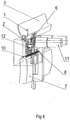
- Fig. 4 the pressing-in devices 8, 8 'are raised to the level of the pressure rail 8, which contains a toothed rack 10, into which a toothed wheel 12 is able to engage, which at the same time engages with the toothed pressure roller 6.
- the latter is rotatable by an electric servomotor 11.
- the cross section of the position is in relation to the piping in Fig. 5 shown.
- Fig. 6 shows the formation of Eind Wegvorraumen 8, 8 'in a view from the side.
- the push-in device 8, 8 ' is prevented from tilting by the two rollers 9 guided one behind the other and that the push-in roller 6 designed as a toothed wheel engages through the roller 9, which engages with the rack 10 via the intermediate gear 12, is in rotary connection.
- the push-in roller 6 designed as a toothed wheel engages through the roller 9, which engages with the rack 10 via the intermediate gear 12, is in rotary connection.
- the rotation of the gears is effected by a servomotor 11, which acts directly on the indenting roller 6.
- the rotational movement is transmitted via the gear 12 to the rack 10, whereby the indenting devices 8, 8 'move out of the starting position along the mouth 4 of the piping groove 3 and thread the piping 2 progressively therein.
- a connected to the piping textile structure, such as a seat cover, can be stretched wrinkle-free and tight on a seat cushion without requiring manual handles.
Landscapes
- Engineering & Computer Science (AREA)
- Mechanical Engineering (AREA)
- Aviation & Aerospace Engineering (AREA)
- Transportation (AREA)
- Treatment Of Fiber Materials (AREA)
Claims (13)
- Procédé permettant d'enfiler un bourrelet de calfeutrage (2) fixé au bord d'une structure plane flexible (1) transversalement dans une rainure de bourrelet (3) qui est équipée d'un étranglement dans la zone de son ouverture (4),
caractérisé en ce que
le bourrelet (2) est saisi dans la zone médiane de la longueur de la rainure (3) par une pince (5) à entraînement motorisé, est enclenchée dans la rainure (3) avec élargissement élastique temporaire de l'ouverture (4) de cette rainure (3), et la pince (5) est ensuite enlevée, et en ce que à l'aide de dispositifs de poussée installés de part et d'autre de la position précédente de la pince (5), le bourrelet (2) est appliqué au fond de la rainure (3), et en ce que, à partir de cette position, le bourrelet (2) est ensuite simultanément enclenché dans les autres zones de la rainure (3) progressivement dans les deux directions opposées A, B. - Procédé conforme à la revendication 1,
caractérisé en ce que
le bourrelet (2) est emboîtée dans la rainure (3) à l'aide d'une pince (5) dans la zone médiane de la longueur de cette rainure, et à partir de cette position, est progressivement enclenché à l'aide de galets (6) dans les autres zones de la rainure (3) dans les deux directions opposées A, B. - Procédé conforme à la revendication 1,
caractérisé en ce que
les galets (6) sont à entraînement motorisé. - Dispositif permettant d'enfiler un bourrelet de calfeutrage (2) fixé au bord d'une structure plane flexible (1) transversalement dans une rainure de bourrelet (3) qui est équipée d'un étranglement dans la zone de son ouverture (4) conformément à l'une des revendications 1 à 3, caractérisé en ce qu'
il est prévu une pince (5) à entraînement motorisé pouvant être actionnée par un signal pour permettre la saisie et l'emboîtement médian du bourrelet (2) dans la rainure (3), en ce que à distance de l'ouverture (4) de la rainure (3) est installé un rail de pression (7) s'étendant parallèlement à sa direction longitudinale, en ce que sur le rail de pression (7) sont montés deux dispositifs de poussée (8, 8') mobiles en coulissement relatif, et en ce que les dispositifs de poussée (8, 8') comprennent au moins un élément de poussée permettant de pousser progressivement le bourrelet (2) dans la rainure (3), ainsi qu'un entraînement permettant de faire avancer les éléments de poussée à partir d'une position centrale sur la totalité de la longueur de l'ouverture de la rainure (3). - Dispositif conforme à la revendication 4,
caractérisé en ce que
l'élément de poussée est formé par un patin glissant. - Dispositif conforme à la revendication 4,
caractérisé en ce que
l'élément de poussée est formé par un galet (6, 6'). - Dispositif conforme à la revendication 4,
caractérisé en ce que
le galet (6, 6') est équipé dans la zone de sa périphérie externe d'une denture s'étendant transversalement à la direction périphérique. - Dispositif conforme à l'une des revendications 4 à 7,
caractérisé en ce que
les dispositifs de poussée (8, 8') sont guidés et s'appuient respectivement sur le rail de pression (7) par l'intermédiaire de galets support (9) situés l'un derrière l'autre dans la direction de déplacement. - Dispositif conforme à l'une des revendications 4 à 8,
caractérisé en ce que
le rail de pression (7) comprend une crémaillère (10) et les dispositifs de poussée (8, 8') comprennent une roue dentée qui est en prise avec la crémaillère (7). - Dispositif conforme à la revendication 9,
caractérisé en ce que
la roue dentée et les galets support (9) sont reliés solidairement en rotation et ne peuvent tourner que conjointement. - Dispositif conforme à la revendication 9 ou 10,
dans lequel l'élément de poussée est formé par un galet (6),
caractérisé en ce que
le galet (6) peut être déplacé en rotation par la roue dentée. - Procédé conforme à l'une des revendications 4 à 11,
caractérisé en ce que
les dispositifs de poussée peuvent être déplacés par coulissement par des moteurs (11, 11'). - Dispositif conforme à la revendication 12,
caractérisé en ce que
les moteurs (11, 11') sont formés par des moteurs électriques actionnables par un signal qui forment un composant des dispositifs de poussée (8, 8').
Applications Claiming Priority (1)
| Application Number | Priority Date | Filing Date | Title |
|---|---|---|---|
| PCT/EP2008/005082 WO2009155940A1 (fr) | 2008-06-24 | 2008-06-24 | Procédé et dispositif pour enfiler une clavette fixée sur le bord d’un produit plat souple dans une rainure de clavette |
Publications (2)
| Publication Number | Publication Date |
|---|---|
| EP2293897A1 EP2293897A1 (fr) | 2011-03-16 |
| EP2293897B1 true EP2293897B1 (fr) | 2017-01-04 |
Family
ID=40380411
Family Applications (1)
| Application Number | Title | Priority Date | Filing Date |
|---|---|---|---|
| EP08773600.5A Active EP2293897B1 (fr) | 2008-06-24 | 2008-06-24 | Procédé et dispositif pour enfiler une clavette fixée sur le bord d un produit plat souple dans une rainure de clavette |
Country Status (2)
| Country | Link |
|---|---|
| EP (1) | EP2293897B1 (fr) |
| WO (1) | WO2009155940A1 (fr) |
Families Citing this family (2)
| Publication number | Priority date | Publication date | Assignee | Title |
|---|---|---|---|---|
| US9399887B2 (en) | 2010-07-08 | 2016-07-26 | Greenstar Technologies Llc | Weatherstripping |
| US8673424B2 (en) * | 2010-07-08 | 2014-03-18 | Greenstar Technologies, LLC. | Snap in weatherstripping |
Family Cites Families (5)
| Publication number | Priority date | Publication date | Assignee | Title |
|---|---|---|---|---|
| DE3021031C2 (de) | 1980-06-03 | 1983-03-31 | Anton Huber GmbH & Co, 8228 Freilassing | Verfahren zum Befestigen mindestens einer Zierleiste an den Oberflächen von Bauteilen, insbesondere von Stoßstangen, Stoßstangenverkleidungen, Abdeckungen, Zierteilen o.dgl. und Vorrichtung zur Ausführung des Verfahrens |
| DE19630753C2 (de) | 1996-07-30 | 1999-06-17 | Lear Corp Gmbh & Co Kg | Vorrichtung zur Montage eines Kederprofils |
| FR2899531B1 (fr) | 2006-04-07 | 2008-06-27 | Faurecia Sieges Automobile | Dispositif d'accrochage d'une coiffe, siege comportant un tel dispositif et outil de mise en place du dispositif d'accrochage |
| FR2905317B1 (fr) * | 2006-09-01 | 2009-05-01 | Cera | Procede d'association par coulissement d'un element de garnissage sur une matelassure |
| DE102007006098B4 (de) * | 2007-02-02 | 2008-12-18 | Frimo Group Gmbh | Verfahren und Vorrichtung zum Einfädeln eines am Rand eines flexiblen Flächengebildes festgelegten Keders in eine Kedernut |
-
2008
- 2008-06-24 WO PCT/EP2008/005082 patent/WO2009155940A1/fr not_active Ceased
- 2008-06-24 EP EP08773600.5A patent/EP2293897B1/fr active Active
Non-Patent Citations (1)
| Title |
|---|
| None * |
Also Published As
| Publication number | Publication date |
|---|---|
| EP2293897A1 (fr) | 2011-03-16 |
| WO2009155940A1 (fr) | 2009-12-30 |
Similar Documents
| Publication | Publication Date | Title |
|---|---|---|
| DE102008012202B4 (de) | Dachfensterrollo mit Spanneinrichtung | |
| DE202009005007U1 (de) | Wickelvorrichtung zum Bedecken von Wandöffnungen oder Fenstern | |
| EP1986876B1 (fr) | Dispositif d'obscurcissement pour une vitre transparente, notamment pour vehicules automobiles | |
| DE10351040B3 (de) | Fensterrollo für Kraftfahrzeuge und Seitenverkleidung mit integrierter Führungsschiene | |
| DE19755533A1 (de) | Farbrollerwalze und Verfahren zu ihrer Herstellung | |
| EP2293897B1 (fr) | Procédé et dispositif pour enfiler une clavette fixée sur le bord d un produit plat souple dans une rainure de clavette | |
| DE102007006098B4 (de) | Verfahren und Vorrichtung zum Einfädeln eines am Rand eines flexiblen Flächengebildes festgelegten Keders in eine Kedernut | |
| DE4219943C1 (en) | Fastening cushion casing to car seat squab support - uses clips, each suspended into pull-rod pushed through squab support | |
| EP1591317B1 (fr) | Couverture d'espace de rangement | |
| DE3309475A1 (de) | Vorrichtung zur befestigung von halteklipsen fuer heizungsrohre an fussbodenheizungselementen | |
| EP3426419B1 (fr) | Procédé permettant de faire coulisser simultanément au moins deux outils de pliage maintenus dans un rail d'un porte-outil et presse de pliage | |
| DE2264596C3 (de) | Vorrichtung zum Bespannen von Wandflächen mit elastischen Bespannstoffen, z.B. Geweben | |
| EP0330086A1 (fr) | Dispositif d'accouplement d'au moins deux bords longitudinaux de structures en forme de pellicules ou de tissus | |
| DE3439921C1 (de) | Element zum Verankern von Wandteilen in der hinterschnittenen, einen Öffnungsschlitz aufweisenden Längsnut eines Aufnahmeteils | |
| DE2609498C3 (de) | Verfahren zum Einbringen eines Dichtstoffstranges in eine Haltenut einer Abdichtungsprofilleiste und Vorrichtung zur Durchführung des Verfahrens | |
| DE102005030707A1 (de) | Fensterrollo für Kraftfahrzeuge mit formschlüssigem Anschlag auf dem Betätigungsglied | |
| EP2631412A2 (fr) | Dispositif de montage d'une bande flexible | |
| DE3109165C2 (de) | Vorrichtung zum Einbringen eines elastischen Dichtungsstranges in eine Fuge | |
| EP2803533B1 (fr) | Dispositif destiné à agencer une barre présentant un canal longitudinal sur un support | |
| DE60124491T2 (de) | Fensterrollo mit progressiv konischer Wickelwelle | |
| DE4028027C2 (de) | Vorrichtung zur Montage von Scheiben | |
| DE102019006789A1 (de) | Beschattungsvorrichtung | |
| DE29716729U1 (de) | Befestigung einer Zier- oder Abdeckleiste | |
| CH714675A2 (de) | Kedersystem. | |
| DE102017122725A1 (de) | Werkzeug und Verfahren zum Befestigen einer Dichtung an einem Befestigungselement, insbesondere eines Kraftfahrzeugs |
Legal Events
| Date | Code | Title | Description |
|---|---|---|---|
| PUAI | Public reference made under article 153(3) epc to a published international application that has entered the european phase |
Free format text: ORIGINAL CODE: 0009012 |
|
| 17P | Request for examination filed |
Effective date: 20101123 |
|
| AK | Designated contracting states |
Kind code of ref document: A1 Designated state(s): AT BE BG CH CY CZ DE DK EE ES FI FR GB GR HR HU IE IS IT LI LT LU LV MC MT NL NO PL PT RO SE SI SK TR |
|
| AX | Request for extension of the european patent |
Extension state: AL BA MK RS |
|
| DAX | Request for extension of the european patent (deleted) | ||
| GRAP | Despatch of communication of intention to grant a patent |
Free format text: ORIGINAL CODE: EPIDOSNIGR1 |
|
| INTG | Intention to grant announced |
Effective date: 20160907 |
|
| GRAS | Grant fee paid |
Free format text: ORIGINAL CODE: EPIDOSNIGR3 |
|
| GRAA | (expected) grant |
Free format text: ORIGINAL CODE: 0009210 |
|
| AK | Designated contracting states |
Kind code of ref document: B1 Designated state(s): AT BE BG CH CY CZ DE DK EE ES FI FR GB GR HR HU IE IS IT LI LT LU LV MC MT NL NO PL PT RO SE SI SK TR |
|
| REG | Reference to a national code |
Ref country code: GB Ref legal event code: FG4D Free format text: NOT ENGLISH |
|
| REG | Reference to a national code |
Ref country code: CH Ref legal event code: EP |
|
| REG | Reference to a national code |
Ref country code: AT Ref legal event code: REF Ref document number: 858772 Country of ref document: AT Kind code of ref document: T Effective date: 20170115 |
|
| REG | Reference to a national code |
Ref country code: IE Ref legal event code: FG4D Free format text: LANGUAGE OF EP DOCUMENT: GERMAN |
|
| REG | Reference to a national code |
Ref country code: DE Ref legal event code: R096 Ref document number: 502008014937 Country of ref document: DE |
|
| REG | Reference to a national code |
Ref country code: LT Ref legal event code: MG4D Ref country code: NL Ref legal event code: MP Effective date: 20170104 |
|
| REG | Reference to a national code |
Ref country code: FR Ref legal event code: PLFP Year of fee payment: 10 |
|
| PG25 | Lapsed in a contracting state [announced via postgrant information from national office to epo] |
Ref country code: NL Free format text: LAPSE BECAUSE OF FAILURE TO SUBMIT A TRANSLATION OF THE DESCRIPTION OR TO PAY THE FEE WITHIN THE PRESCRIBED TIME-LIMIT Effective date: 20170104 |
|
| PG25 | Lapsed in a contracting state [announced via postgrant information from national office to epo] |
Ref country code: LT Free format text: LAPSE BECAUSE OF FAILURE TO SUBMIT A TRANSLATION OF THE DESCRIPTION OR TO PAY THE FEE WITHIN THE PRESCRIBED TIME-LIMIT Effective date: 20170104 Ref country code: NO Free format text: LAPSE BECAUSE OF FAILURE TO SUBMIT A TRANSLATION OF THE DESCRIPTION OR TO PAY THE FEE WITHIN THE PRESCRIBED TIME-LIMIT Effective date: 20170404 Ref country code: IS Free format text: LAPSE BECAUSE OF FAILURE TO SUBMIT A TRANSLATION OF THE DESCRIPTION OR TO PAY THE FEE WITHIN THE PRESCRIBED TIME-LIMIT Effective date: 20170504 Ref country code: FI Free format text: LAPSE BECAUSE OF FAILURE TO SUBMIT A TRANSLATION OF THE DESCRIPTION OR TO PAY THE FEE WITHIN THE PRESCRIBED TIME-LIMIT Effective date: 20170104 Ref country code: GR Free format text: LAPSE BECAUSE OF FAILURE TO SUBMIT A TRANSLATION OF THE DESCRIPTION OR TO PAY THE FEE WITHIN THE PRESCRIBED TIME-LIMIT Effective date: 20170405 Ref country code: HR Free format text: LAPSE BECAUSE OF FAILURE TO SUBMIT A TRANSLATION OF THE DESCRIPTION OR TO PAY THE FEE WITHIN THE PRESCRIBED TIME-LIMIT Effective date: 20170104 |
|
| PG25 | Lapsed in a contracting state [announced via postgrant information from national office to epo] |
Ref country code: LV Free format text: LAPSE BECAUSE OF FAILURE TO SUBMIT A TRANSLATION OF THE DESCRIPTION OR TO PAY THE FEE WITHIN THE PRESCRIBED TIME-LIMIT Effective date: 20170104 Ref country code: PL Free format text: LAPSE BECAUSE OF FAILURE TO SUBMIT A TRANSLATION OF THE DESCRIPTION OR TO PAY THE FEE WITHIN THE PRESCRIBED TIME-LIMIT Effective date: 20170104 Ref country code: SE Free format text: LAPSE BECAUSE OF FAILURE TO SUBMIT A TRANSLATION OF THE DESCRIPTION OR TO PAY THE FEE WITHIN THE PRESCRIBED TIME-LIMIT Effective date: 20170104 Ref country code: BG Free format text: LAPSE BECAUSE OF FAILURE TO SUBMIT A TRANSLATION OF THE DESCRIPTION OR TO PAY THE FEE WITHIN THE PRESCRIBED TIME-LIMIT Effective date: 20170404 Ref country code: ES Free format text: LAPSE BECAUSE OF FAILURE TO SUBMIT A TRANSLATION OF THE DESCRIPTION OR TO PAY THE FEE WITHIN THE PRESCRIBED TIME-LIMIT Effective date: 20170104 Ref country code: PT Free format text: LAPSE BECAUSE OF FAILURE TO SUBMIT A TRANSLATION OF THE DESCRIPTION OR TO PAY THE FEE WITHIN THE PRESCRIBED TIME-LIMIT Effective date: 20170504 |
|
| REG | Reference to a national code |
Ref country code: DE Ref legal event code: R097 Ref document number: 502008014937 Country of ref document: DE |
|
| PG25 | Lapsed in a contracting state [announced via postgrant information from national office to epo] |
Ref country code: EE Free format text: LAPSE BECAUSE OF FAILURE TO SUBMIT A TRANSLATION OF THE DESCRIPTION OR TO PAY THE FEE WITHIN THE PRESCRIBED TIME-LIMIT Effective date: 20170104 Ref country code: CZ Free format text: LAPSE BECAUSE OF FAILURE TO SUBMIT A TRANSLATION OF THE DESCRIPTION OR TO PAY THE FEE WITHIN THE PRESCRIBED TIME-LIMIT Effective date: 20170104 Ref country code: RO Free format text: LAPSE BECAUSE OF FAILURE TO SUBMIT A TRANSLATION OF THE DESCRIPTION OR TO PAY THE FEE WITHIN THE PRESCRIBED TIME-LIMIT Effective date: 20170104 Ref country code: SK Free format text: LAPSE BECAUSE OF FAILURE TO SUBMIT A TRANSLATION OF THE DESCRIPTION OR TO PAY THE FEE WITHIN THE PRESCRIBED TIME-LIMIT Effective date: 20170104 |
|
| PLBE | No opposition filed within time limit |
Free format text: ORIGINAL CODE: 0009261 |
|
| STAA | Information on the status of an ep patent application or granted ep patent |
Free format text: STATUS: NO OPPOSITION FILED WITHIN TIME LIMIT |
|
| PG25 | Lapsed in a contracting state [announced via postgrant information from national office to epo] |
Ref country code: DK Free format text: LAPSE BECAUSE OF FAILURE TO SUBMIT A TRANSLATION OF THE DESCRIPTION OR TO PAY THE FEE WITHIN THE PRESCRIBED TIME-LIMIT Effective date: 20170104 |
|
| 26N | No opposition filed |
Effective date: 20171005 |
|
| PG25 | Lapsed in a contracting state [announced via postgrant information from national office to epo] |
Ref country code: MC Free format text: LAPSE BECAUSE OF FAILURE TO SUBMIT A TRANSLATION OF THE DESCRIPTION OR TO PAY THE FEE WITHIN THE PRESCRIBED TIME-LIMIT Effective date: 20170104 |
|
| REG | Reference to a national code |
Ref country code: CH Ref legal event code: PL |
|
| PG25 | Lapsed in a contracting state [announced via postgrant information from national office to epo] |
Ref country code: SI Free format text: LAPSE BECAUSE OF FAILURE TO SUBMIT A TRANSLATION OF THE DESCRIPTION OR TO PAY THE FEE WITHIN THE PRESCRIBED TIME-LIMIT Effective date: 20170104 |
|
| REG | Reference to a national code |
Ref country code: IE Ref legal event code: MM4A |
|
| PG25 | Lapsed in a contracting state [announced via postgrant information from national office to epo] |
Ref country code: LI Free format text: LAPSE BECAUSE OF NON-PAYMENT OF DUE FEES Effective date: 20170630 Ref country code: LU Free format text: LAPSE BECAUSE OF NON-PAYMENT OF DUE FEES Effective date: 20170624 Ref country code: CH Free format text: LAPSE BECAUSE OF NON-PAYMENT OF DUE FEES Effective date: 20170630 Ref country code: IE Free format text: LAPSE BECAUSE OF NON-PAYMENT OF DUE FEES Effective date: 20170624 |
|
| REG | Reference to a national code |
Ref country code: BE Ref legal event code: MM Effective date: 20170630 |
|
| REG | Reference to a national code |
Ref country code: FR Ref legal event code: PLFP Year of fee payment: 11 |
|
| REG | Reference to a national code |
Ref country code: AT Ref legal event code: MM01 Ref document number: 858772 Country of ref document: AT Kind code of ref document: T Effective date: 20170624 |
|
| PG25 | Lapsed in a contracting state [announced via postgrant information from national office to epo] |
Ref country code: BE Free format text: LAPSE BECAUSE OF NON-PAYMENT OF DUE FEES Effective date: 20170630 |
|
| PG25 | Lapsed in a contracting state [announced via postgrant information from national office to epo] |
Ref country code: MT Free format text: LAPSE BECAUSE OF FAILURE TO SUBMIT A TRANSLATION OF THE DESCRIPTION OR TO PAY THE FEE WITHIN THE PRESCRIBED TIME-LIMIT Effective date: 20170104 |
|
| PG25 | Lapsed in a contracting state [announced via postgrant information from national office to epo] |
Ref country code: AT Free format text: LAPSE BECAUSE OF NON-PAYMENT OF DUE FEES Effective date: 20170624 |
|
| PG25 | Lapsed in a contracting state [announced via postgrant information from national office to epo] |
Ref country code: HU Free format text: LAPSE BECAUSE OF FAILURE TO SUBMIT A TRANSLATION OF THE DESCRIPTION OR TO PAY THE FEE WITHIN THE PRESCRIBED TIME-LIMIT; INVALID AB INITIO Effective date: 20080624 |
|
| PG25 | Lapsed in a contracting state [announced via postgrant information from national office to epo] |
Ref country code: CY Free format text: LAPSE BECAUSE OF NON-PAYMENT OF DUE FEES Effective date: 20170104 |
|
| PG25 | Lapsed in a contracting state [announced via postgrant information from national office to epo] |
Ref country code: TR Free format text: LAPSE BECAUSE OF FAILURE TO SUBMIT A TRANSLATION OF THE DESCRIPTION OR TO PAY THE FEE WITHIN THE PRESCRIBED TIME-LIMIT Effective date: 20170104 |
|
| P01 | Opt-out of the competence of the unified patent court (upc) registered |
Effective date: 20230502 |
|
| PGFP | Annual fee paid to national office [announced via postgrant information from national office to epo] |
Ref country code: DE Payment date: 20250605 Year of fee payment: 18 |
|
| PGFP | Annual fee paid to national office [announced via postgrant information from national office to epo] |
Ref country code: GB Payment date: 20250620 Year of fee payment: 18 |
|
| PGFP | Annual fee paid to national office [announced via postgrant information from national office to epo] |
Ref country code: FR Payment date: 20250618 Year of fee payment: 18 |
|
| PGFP | Annual fee paid to national office [announced via postgrant information from national office to epo] |
Ref country code: IT Payment date: 20250630 Year of fee payment: 18 |