EP2294324B1 - Ensemble boulon à expansion radiale - Google Patents
Ensemble boulon à expansion radiale Download PDFInfo
- Publication number
- EP2294324B1 EP2294324B1 EP09770934.9A EP09770934A EP2294324B1 EP 2294324 B1 EP2294324 B1 EP 2294324B1 EP 09770934 A EP09770934 A EP 09770934A EP 2294324 B1 EP2294324 B1 EP 2294324B1
- Authority
- EP
- European Patent Office
- Prior art keywords
- bolt assembly
- radially expanding
- expanding
- washer
- radially
- Prior art date
- Legal status (The legal status is an assumption and is not a legal conclusion. Google has not performed a legal analysis and makes no representation as to the accuracy of the status listed.)
- Active
Links
Images

Classifications
-
- F—MECHANICAL ENGINEERING; LIGHTING; HEATING; WEAPONS; BLASTING
- F16—ENGINEERING ELEMENTS AND UNITS; GENERAL MEASURES FOR PRODUCING AND MAINTAINING EFFECTIVE FUNCTIONING OF MACHINES OR INSTALLATIONS; THERMAL INSULATION IN GENERAL
- F16B—DEVICES FOR FASTENING OR SECURING CONSTRUCTIONAL ELEMENTS OR MACHINE PARTS TOGETHER, e.g. NAILS, BOLTS, CIRCLIPS, CLAMPS, CLIPS OR WEDGES; JOINTS OR JOINTING
- F16B5/00—Joining sheets or plates, e.g. panels, to one another or to strips or bars parallel to them
- F16B5/02—Joining sheets or plates, e.g. panels, to one another or to strips or bars parallel to them by means of fastening members using screw-thread
-
- F—MECHANICAL ENGINEERING; LIGHTING; HEATING; WEAPONS; BLASTING
- F16—ENGINEERING ELEMENTS AND UNITS; GENERAL MEASURES FOR PRODUCING AND MAINTAINING EFFECTIVE FUNCTIONING OF MACHINES OR INSTALLATIONS; THERMAL INSULATION IN GENERAL
- F16B—DEVICES FOR FASTENING OR SECURING CONSTRUCTIONAL ELEMENTS OR MACHINE PARTS TOGETHER, e.g. NAILS, BOLTS, CIRCLIPS, CLAMPS, CLIPS OR WEDGES; JOINTS OR JOINTING
- F16B13/00—Dowels or other devices fastened in walls or the like by inserting them in holes made therein for that purpose
- F16B13/04—Dowels or other devices fastened in walls or the like by inserting them in holes made therein for that purpose with parts gripping in the hole or behind the reverse side of the wall after inserting from the front
- F16B13/06—Dowels or other devices fastened in walls or the like by inserting them in holes made therein for that purpose with parts gripping in the hole or behind the reverse side of the wall after inserting from the front combined with expanding sleeve
-
- F—MECHANICAL ENGINEERING; LIGHTING; HEATING; WEAPONS; BLASTING
- F16—ENGINEERING ELEMENTS AND UNITS; GENERAL MEASURES FOR PRODUCING AND MAINTAINING EFFECTIVE FUNCTIONING OF MACHINES OR INSTALLATIONS; THERMAL INSULATION IN GENERAL
- F16B—DEVICES FOR FASTENING OR SECURING CONSTRUCTIONAL ELEMENTS OR MACHINE PARTS TOGETHER, e.g. NAILS, BOLTS, CIRCLIPS, CLAMPS, CLIPS OR WEDGES; JOINTS OR JOINTING
- F16B5/00—Joining sheets or plates, e.g. panels, to one another or to strips or bars parallel to them
- F16B5/02—Joining sheets or plates, e.g. panels, to one another or to strips or bars parallel to them by means of fastening members using screw-thread
- F16B5/0258—Joining sheets or plates, e.g. panels, to one another or to strips or bars parallel to them by means of fastening members using screw-thread using resiliently deformable sleeves, grommets or inserts
-
- F—MECHANICAL ENGINEERING; LIGHTING; HEATING; WEAPONS; BLASTING
- F16—ENGINEERING ELEMENTS AND UNITS; GENERAL MEASURES FOR PRODUCING AND MAINTAINING EFFECTIVE FUNCTIONING OF MACHINES OR INSTALLATIONS; THERMAL INSULATION IN GENERAL
- F16B—DEVICES FOR FASTENING OR SECURING CONSTRUCTIONAL ELEMENTS OR MACHINE PARTS TOGETHER, e.g. NAILS, BOLTS, CIRCLIPS, CLAMPS, CLIPS OR WEDGES; JOINTS OR JOINTING
- F16B35/00—Screw-bolts; Stay-bolts; Screw-threaded studs; Screws; Set screws
- F16B35/04—Screw-bolts; Stay-bolts; Screw-threaded studs; Screws; Set screws with specially-shaped head or shaft in order to fix the bolt on or in an object
Definitions
- the present invention relates to a bolt assembly, and in particular to a radially expanding bolt assembly.
- the known radially expanding bolt assembly includes an outer tubular expansible element formed as a sleeve with an inner tapered portion and a mating inner expanding element formed as an inner stud with an outer tapered portion cooperating with the tapered portion of the sleeve.
- the outer sleeve is inserted in a hole of an object to be tensioned, for example two adjoining flanges to be connected with one another. After this, the inner stud is inserted into the outer sleeve and pulled by external means to force the tapered portions to slide over one another and therefore to expand the outer sleeve.
- the bolt assembly known from FR-A-1 053 495 is working in a similar manner.
- hydraulic tools or a plurality of jack screws are used as external means for applying a tensile load to the radially expanding bolt assembly. It is believed that the existing radially expanding bolt assemblies can be further improved.
- a radially expanding bolt assembly comprising a hollow element insertable into a hole of an object, having an axis and expansible in a radial direction, said hollow element having an inner surface with at least one inner surface portion which is tapered; an expanding element insertable in said hollow element and having an outer surface with at least one outer surface portion which is tapered, cooperating with said inner tapered surface portion of said hollow element, said expanding element having two opposite axial ends each engageable with an additional element configured for displacement of said expanding element in opposite axial directions for tightening the bolt assembly and for loosening the bolt assembly correspondingly; and a washer positionable between the object and one of the additional elements at one of said axial ends, so that said one additional element displaces said expanding element in one axial direction and due to cooperation of said inner and outer tapered surface portions expands said hollow element to clamp it in the hole of the object, while the other additional element displaces said expanding element
- the expanding element has engaging formations provided on the opposite axial ends and engageable by the additional elements.
- a further feature of the present invention resides in that the washer is non-rotatably connected with one axial end of the hollow element, and means is provided for non-rotatably connecting the washer with the one axial end of the hollow element.
- a further feature of the present invention resides in that the washer has means for engaging by a tool used for turning of the one additional element and absorbing a reaction force generated during application of an action force by the tool to the one additional element.
- a further feature of the present invention resides in that the hollow element at the opposite axial end has a radially projecting portion.
- a further feature of the present invention resides in that the projecting portion is provided with means for engaging by a tool to absorb a reaction force generated during the application of an action force by the tool to the other additional element for displacing the expanding element in the opposite axial direction.
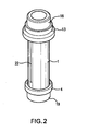
- a radially expanding bolt assembly of the present invention includes an outer hollow tubular member which is formed as a sleeve (1).
- the sleeve (1) has an outer cylindrical surface, and also an inner surface which includes at least one tapered portion (2).
- the sleeve (1) has an axis (2) and two axial ends (3, 4).
- the axial end (3) of the sleeve (2) is provided with engaging formations, formed for example as axially extending splines, or a hexagonal surface, or a star-shaped surface, or other polygonal formations (5), while the opposite axial end (4), which is formed as a radially projecting flange, also has engaging formations, which also can be formed for example as axially extending splines or a hexagonal surface, or a star-shaped surface, or other polygonal formations (6), for the purposes which will be explained hereinbelow.
- the radially expanding bolt assembly further has an expanding member which is formed with an inner stud (7).
- the stud (7) has two opposite axial ends (8, 9) each provided with engaging formations, for example, threads (10, 11), for the purposes which will be explained hereinbelow.
- the stud (7) has an outer surface with at least one portion (12) which is tapered substantially in correspondence with the tapered portion (2) of the inner surface of the sleeve (1).
- the radially expanding bolt assembly in accordance with the present invention further has a washer which is identified with reference numeral (13).
- the washer (13) has an inner surface provided with inner splines or a hexagonal surface, or a star-shaped surface, or other polygonal formations (14) which are engageable with the outer polygonal formations (5) of the sleeve (1) so as to connect the washer (13) with a sleeve (1) non-rotatably around an axis (A).
- the washer (13) further has outer engaging formations, formed for example as outer axially extending splines or a hexagonal surface, or a star-shaped surface, or other polygonal formations (15) to be engaged by a tool which tightens or loosens the bolt assembly.
- a stepped nut (16) has a portion insertable into an opening of the washer (13) and having an inner thread (17) engageable with the outer thread of the stud (7).
- the nut (16) also has an outer portion provided with a plurality of axially extending splines or a hexagonal surface, or a star-shaped surface, or other polygonal formations (18).
- Another nut (19) has a portion insertable into the opposite end of the sleeve (1) and having an inner thread (20) engageable with the outer thread on the opposite end of the stud (7).
- the nut (19) also has an outer portion provided with a plurality of axially extending splines or a hexagonal surface, or a star-shaped surface, or other polygonal formations (21).
- the sleeve (1) is expansible in a radial direction. This can be achieved by making the sleeve (1) with a thin stretchable wall, by providing longitudinal slots (22) in it, etc.
- the radially expanding bolt assembly in accordance with the present invention operates in the following manner:
- the outer sleeve (1) first passes through into inner holes (23, 24) of an object composed of two flanges (25, 26) to be aligned and fixed with one another. Then the washer (13) is fitted on the right axial end (3) of the outer sleeve (1) and its inner polygonal formations engage with the outer polygonal formations of the sleeve (1).
- the stud (7) is introduced into the interior of the sleeve (1), and the nut (16) is screwed on the right axial end of the stud (7).
- a tool for example a torque wrench, is applied to the expanding bolt assembly.
- the action force is applied by a rotating part of the tool which engages the polygonal formations (18) of the nut (16), while a reaction-absorbing part of the tool, for example an immobile reaction element, engages the polygonal formations (15) of the washer (13).
- the nut (19) is screwed on the left axial end of the stud (7) and turned by a part of the tool applying an action force, while another part of the tool, which is stationary and absorbs the reaction force, engages with the polygonal formations of the flange (4) of the sleeve (1).
- the nut (16) is unscrewed from the right axial end of the stud (7).
- the stud is pulled in an opposite axial direction, the tapered portion of the outer surface of the stud (7) disengages from the tapered portion of the inner surface of the sleeve (1), so as to eliminate the radial outward pressure of the stud (7) on the sleeve (1).
- the outer diameter of the outer sleeve (1) is reduced and it disengages from the inner walls of the holes (23, 24) of the object (25, 26).
- the inventive assembly can be pulled through the openings (23, 24) to the left and removed from the object (25, 26).
Landscapes
- Engineering & Computer Science (AREA)
- General Engineering & Computer Science (AREA)
- Mechanical Engineering (AREA)
- Dowels (AREA)
- Mutual Connection Of Rods And Tubes (AREA)
- Clamps And Clips (AREA)
- Bolts, Nuts, And Washers (AREA)
Claims (10)
- Ensemble de boulon à expansion radiale, comprenant un élément creux (1) pouvant être inséré dans un trou d'un objet, présentant un axe et étant expansible dans une direction radiale, ledit élément creux (1) présentant une surface intérieure avec au moins une partie de surface intérieure (2) qui est biseautée ; un élément d'expansion (7) pouvant être inséré dans ledit élément creux (1) et présentant une surface extérieure avec au moins une partie de surface extérieure (12) qui est biseautée, en coopération avec ladite partie de surface biseautée intérieure (2) dudit élément creux (1), caractérisé en ce que l'élément d'expansion (7) comporte deux extrémités axiales opposées (3, 4) chacune pouvant être engagée avec un élément supplémentaire (16, 19) configuré pour le déplacement dudit élément d'expansion (7) dans des directions axiales opposées pour le serrage de l'ensemble de boulon et pour le desserrage de l'ensemble de boulon de manière correspondante ; et en ce qu'une rondelle (13) peut être disposée entre l'objet et un premier élément parmi les éléments supplémentaires (16, 19) sur une première extrémité parmi lesdites extrémités axiales (3, 4), de sorte que ledit premier élément supplémentaire (16, 19) déplace ledit élément d'expansion (7) dans une première direction axiale et, en raison de la coopération desdites parties de surfaces biseautées intérieure et extérieure (2, 12), qu'il étend ledit élément creux (1) afin de le fixer dans le trou de l'objet, pendant que le deuxième élément supplémentaire (16, 19) déplace ledit élément d'expansion (7) dans une direction axiale opposée et que lesdites parties de surfaces biseautées intérieure et extérieure (2, 12) se désengagent l'une de l'autre afin que ledit élément creux (1) se contracte et que l'ensemble de boulon à expansion radiale peut être retiré du trou dudit objet.
- Ensemble de boulon à expansion radiale selon la revendication 1, où ledit élément d'expansion (7) présente des formations d'engagement (5, 6) prévues sur lesdites extrémités axiales opposées (3, 4) et pouvant être engagées par les éléments supplémentaires (16, 19).
- Ensemble de boulon à expansion radiale selon la revendication 2, où lesdites formations d'engagement (5, 6) sur lesdites extrémités axiales opposées (3, 4) dudit élément d'expansion (7) comportent des filetages (10, 11).
- Ensemble de boulon à expansion radiale selon la revendication 1, où ladite rondelle (13) est reliée sans possibilité de rotation à une première extrémité axiale (3) dudit élément creux (7) ; et comprenant en outre un moyen (5) destiné à relier sans possibilité de rotation ladite rondelle (13) à ladite première extrémité axiale (3) dudit élément creux (7).
- Ensemble de boulon à expansion radiale selon la revendication 4, où ledit moyen (5) destiné à relier sans possibilité de rotation ladite rondelle (13) à ladite première extrémité axiale (3) dudit élément creux (7) comprend des formations polygonales.
- Ensemble de boulon à expansion radiale selon la revendication 1, où ladite rondelle (13) comporte un moyen (15) destiné à être engagé par un outil utilisé pour tourner ledit premier élément supplémentaire (16) et à absorber une force de réaction générée lors de l'application d'une force d'action par l'outil sur ledit premier élément supplémentaire (16).
- Ensemble de boulon à expansion radiale selon la revendication 6, où ledit moyen (15) destiné à être engagé par un outil comprend des formations polygonales.
- Ensemble de boulon à expansion radiale selon la revendication 1, où ledit élément creux (1) à ladite extrémité axiale opposée (3, 4) comporte une partie radialement saillante.
- Ensemble de boulon à expansion radiale selon la revendication 8, où ladite partie saillante est dotée d'un moyen destiné à être engagé par un outil permettant d'absorber une force de réaction générée lors de l'application d'une force d'action par l'outil sur le deuxième élément supplémentaire (19) pour le déplacement dudit élément d'expansion dans la direction axiale opposée.
- Ensemble de boulon à expansion radiale selon la revendication 3, où lesdits éléments supplémentaires (16, 19) sont des écrous filetés.
Priority Applications (2)
| Application Number | Priority Date | Filing Date | Title |
|---|---|---|---|
| SI200930908T SI2294324T1 (sl) | 2008-06-26 | 2009-06-24 | Radialno povečljiv sestav sornika |
| PL09770934T PL2294324T3 (pl) | 2008-06-26 | 2009-06-24 | Zespół śruby rozprężny promieniowo |
Applications Claiming Priority (3)
| Application Number | Priority Date | Filing Date | Title |
|---|---|---|---|
| US7579108P | 2008-06-26 | 2008-06-26 | |
| US12/425,518 US8057145B2 (en) | 2008-06-26 | 2009-04-17 | Radially expanding bolt assembly |
| PCT/US2009/048445 WO2009158401A1 (fr) | 2008-06-26 | 2009-06-24 | Ensemble boulon à expansion radiale |
Publications (2)
| Publication Number | Publication Date |
|---|---|
| EP2294324A1 EP2294324A1 (fr) | 2011-03-16 |
| EP2294324B1 true EP2294324B1 (fr) | 2014-01-22 |
Family
ID=40943498
Family Applications (1)
| Application Number | Title | Priority Date | Filing Date |
|---|---|---|---|
| EP09770934.9A Active EP2294324B1 (fr) | 2008-06-26 | 2009-06-24 | Ensemble boulon à expansion radiale |
Country Status (24)
| Country | Link |
|---|---|
| US (1) | US8057145B2 (fr) |
| EP (1) | EP2294324B1 (fr) |
| JP (1) | JP5237448B2 (fr) |
| KR (1) | KR101565450B1 (fr) |
| CN (1) | CN102076977B (fr) |
| AU (1) | AU2009262249B2 (fr) |
| BR (1) | BRPI0910215B1 (fr) |
| CA (2) | CA2728770C (fr) |
| CO (1) | CO6351819A2 (fr) |
| DE (1) | DE112009001605B4 (fr) |
| DK (1) | DK2294324T3 (fr) |
| EA (1) | EA018737B1 (fr) |
| ES (1) | ES2455117T3 (fr) |
| GB (1) | GB2472958B (fr) |
| HR (1) | HRP20140345T1 (fr) |
| MX (1) | MX2010014375A (fr) |
| PE (1) | PE20110445A1 (fr) |
| PL (1) | PL2294324T3 (fr) |
| PT (1) | PT2294324E (fr) |
| SI (1) | SI2294324T1 (fr) |
| TR (1) | TR201010721T1 (fr) |
| TW (1) | TWI477701B (fr) |
| WO (1) | WO2009158401A1 (fr) |
| ZA (1) | ZA201009219B (fr) |
Families Citing this family (26)
| Publication number | Priority date | Publication date | Assignee | Title |
|---|---|---|---|---|
| DE102005052014B4 (de) * | 2005-11-02 | 2008-03-20 | Airbus Deutschland Gmbh | Kegelbolzenverbindung sowie Verwendung einer Kegelbolzenverbindung |
| DE102007044404A1 (de) * | 2007-09-18 | 2009-03-19 | P&S Vorspannsysteme Ag | Verbindungsanordnung bzw. Verbindungsverfahren mit allseitigem Kraftschluss |
| FR2946707B1 (fr) * | 2009-06-13 | 2011-05-20 | Lisi Aerospace | Famille de dispositifs de fixation a conicite variable. |
| DE102013111012B4 (de) * | 2013-10-04 | 2015-05-13 | Putsch Gmbh & Co. Kg | Anordnung zur lösbaren Verbindung einer Buchse mit einem zu klemmenden Bauteil |
| KR101454126B1 (ko) * | 2013-10-31 | 2014-10-22 | 현대중공업 주식회사 | 그레이팅 고정구 |
| CN104807330B (zh) * | 2014-01-24 | 2017-09-05 | 上海华林工业气体有限公司 | 一种转化炉观察孔内异型耐火砖的固定装置 |
| EP2933513A1 (fr) * | 2014-04-15 | 2015-10-21 | Siemens Aktiengesellschaft | Dispositif d'accouplement destiné à relier un embrayage à un ensemble de turbine |
| CN104235201A (zh) * | 2014-07-01 | 2014-12-24 | 杭州福朗机电科技有限公司 | 一种联轴器螺栓连接结构 |
| DE102014014624A1 (de) | 2014-10-01 | 2016-04-07 | Frank Weidermann | Insert für eine Verbindung mit Sandwich Komponenten |
| CN104632834A (zh) * | 2015-01-30 | 2015-05-20 | 无锡市曙光高强度紧固件有限公司 | 钢结构用六角头螺栓 |
| CN109804168B (zh) * | 2016-08-16 | 2021-09-07 | 凯特克分部尤尼克斯公司 | 用于紧固和/或对齐物体的装置 |
| DE102017218016A1 (de) * | 2016-10-26 | 2018-04-26 | Aktiebolaget Skf | Bolzenanordnung, Verbindungsanordnung und Verfahren zum Demontieren einer Verbindungsanordnung |
| DE102017218015A1 (de) * | 2016-10-26 | 2018-04-26 | Aktiebolaget Skf | Bolzenanordnung, Verbindungsanordnung und Verfahren zum Befestigen einer Verbindungsanordnung |
| DE102017111665A1 (de) * | 2017-05-29 | 2018-11-29 | Profil Verbindungstechnik Gmbh & Co. Kg | Klemmeinrichtung |
| US11415158B2 (en) * | 2017-10-18 | 2022-08-16 | Heico Befestigungstechnik Gmbh | Expansion bolt, and connection assembly comprising such an expansion bolt |
| US10501939B2 (en) | 2017-12-22 | 2019-12-10 | Lance Nill | Anchor platform assembly |
| EA202091771A1 (ru) * | 2018-02-20 | 2021-01-27 | Лэнс Нилл | Объединенный узел фиксатора и крепежной детали |
| CN108678426B (zh) * | 2018-04-28 | 2020-02-14 | 温州科技职业学院 | 一种园林廊架 |
| CN109764042A (zh) * | 2018-11-23 | 2019-05-17 | 宁波凯荣船用机械有限公司 | 一种开槽液压膨胀螺栓及其使用方法 |
| CN113710906B (zh) * | 2019-03-15 | 2023-08-08 | 阿久曼特知识产权有限公司 | 使用具有纵向凹槽的可变形套筒的螺栓连接接头 |
| US11434947B1 (en) * | 2020-01-20 | 2022-09-06 | CS&P Technologies LP | Stay rod assembly for a fluid pump |
| WO2021202083A1 (fr) * | 2020-04-01 | 2021-10-07 | Hubbell Incorporated | Éléments de fixation filetés dissociables et connecteurs électriques dotés de tels éléments de fixation |
| US11008757B1 (en) * | 2020-04-01 | 2021-05-18 | Decker Hall Innovations, LLC | Method for securing multiple layers of roofing materials |
| KR102562068B1 (ko) * | 2021-04-23 | 2023-08-02 | (주)엠아이알 | 조립되는 수납대의 연결구조 |
| WO2023196797A1 (fr) | 2022-04-07 | 2023-10-12 | Hubbell Incorporated | Éléments de fixation filetés détachables |
| DE102022113905A1 (de) * | 2022-06-02 | 2023-12-07 | Purem GmbH | Anschlusseinheit |
Family Cites Families (16)
| Publication number | Priority date | Publication date | Assignee | Title |
|---|---|---|---|---|
| US1596856A (en) * | 1924-11-08 | 1926-08-17 | John C Setlow | Expansion bushing for bolts |
| US1767019A (en) * | 1927-04-08 | 1930-06-24 | Sergeeff George | Dowel |
| FR1053495A (fr) * | 1952-04-07 | 1954-02-02 | Dispositif pour l'assemblage d'éléments préfabriqués | |
| JPS5642712A (en) * | 1979-09-18 | 1981-04-21 | Uesutan Ekusupurooraazu Ltd | Anchor and anchor unit |
| JPS5694015A (en) * | 1979-12-25 | 1981-07-30 | Hainku Horukaa | Bolt |
| AU1116483A (en) * | 1982-10-25 | 1984-05-03 | Donald Keith Alman | Fixing bolt |
| DE3346537A1 (de) * | 1983-12-22 | 1985-07-11 | Hilti Ag, Schaan | Spreizanker |
| US4743138A (en) * | 1986-02-24 | 1988-05-10 | Alsthom | Device for coupling two flanged shaft ends |
| GB2214594A (en) * | 1988-01-27 | 1989-09-06 | Denis Lyn Crundall Allen | Spacer for box sections |
| FR2651815B1 (fr) * | 1989-09-11 | 1993-02-19 | De Lorenzi Remy | Dispositif d'assemblage demontable pour elements jointifs de construction de batiment. |
| JPH0656173B2 (ja) * | 1991-05-29 | 1994-07-27 | 中一精機株式会社 | スラスト段部付タップレスボルト |
| US6629808B1 (en) * | 2000-10-31 | 2003-10-07 | Caterpillar Inc | Expandable mounting pin arrangement |
| GB2383105A (en) * | 2001-12-11 | 2003-06-18 | Rolls Royce Plc | Expansion bolt assembly |
| DE10233287A1 (de) * | 2002-07-18 | 2004-02-05 | Heying, Gerhard, Dipl.-Ing. | Schwerlastdübel |
| CN2560784Y (zh) * | 2002-06-25 | 2003-07-16 | 汤铁 | 连接螺栓 |
| ES1062476Y (es) * | 2006-03-24 | 2006-09-16 | Larrea Guillermo Petri | Perno a cortadura y traccion de diametro variable |
-
2009
- 2009-04-17 US US12/425,518 patent/US8057145B2/en active Active
- 2009-06-24 TR TR2010/10721T patent/TR201010721T1/xx unknown
- 2009-06-24 CA CA2728770A patent/CA2728770C/fr active Active
- 2009-06-24 CN CN2009801238245A patent/CN102076977B/zh active Active
- 2009-06-24 EA EA201001825A patent/EA018737B1/ru not_active IP Right Cessation
- 2009-06-24 TW TW098121148A patent/TWI477701B/zh active
- 2009-06-24 PL PL09770934T patent/PL2294324T3/pl unknown
- 2009-06-24 EP EP09770934.9A patent/EP2294324B1/fr active Active
- 2009-06-24 MX MX2010014375A patent/MX2010014375A/es active IP Right Grant
- 2009-06-24 CA CA2862223A patent/CA2862223C/fr active Active
- 2009-06-24 AU AU2009262249A patent/AU2009262249B2/en active Active
- 2009-06-24 BR BRPI0910215-9A patent/BRPI0910215B1/pt active IP Right Grant
- 2009-06-24 DE DE112009001605.7T patent/DE112009001605B4/de active Active
- 2009-06-24 ES ES09770934.9T patent/ES2455117T3/es active Active
- 2009-06-24 DK DK09770934.9T patent/DK2294324T3/en active
- 2009-06-24 KR KR1020117002000A patent/KR101565450B1/ko active Active
- 2009-06-24 PE PE2010001179A patent/PE20110445A1/es active IP Right Grant
- 2009-06-24 SI SI200930908T patent/SI2294324T1/sl unknown
- 2009-06-24 GB GB1021496.3A patent/GB2472958B/en active Active
- 2009-06-24 HR HRP20140345AT patent/HRP20140345T1/hr unknown
- 2009-06-24 PT PT97709349T patent/PT2294324E/pt unknown
- 2009-06-24 JP JP2011516581A patent/JP5237448B2/ja active Active
- 2009-06-24 WO PCT/US2009/048445 patent/WO2009158401A1/fr not_active Ceased
-
2010
- 2010-12-22 ZA ZA2010/09219A patent/ZA201009219B/en unknown
- 2010-12-23 CO CO10161845A patent/CO6351819A2/es active IP Right Grant
Also Published As
Similar Documents
| Publication | Publication Date | Title |
|---|---|---|
| CA2862223C (fr) | Ensemble boulon a expansion radiale | |
| EP1755832B1 (fr) | Ameliorations apportees a des verins hydrauliques de mise en tension | |
| KR20050039511A (ko) | 와샤, 와샤가 구비된 고정구, 대상물의 고정방법과대상물고정용 동력공구 | |
| US20020106256A1 (en) | Expandable anchorage | |
| CN106640914A (zh) | 径向锁紧的防松止退螺母 | |
| GB2245326A (en) | Expansion bolt assembly | |
| EP3500758B1 (fr) | Appareil de fixation et/ou d'alignement d'objets | |
| JP2005114169A (ja) | 支持ボルトジョイント | |
| EP4028671B1 (fr) | Cheville à expansion | |
| EP4222386B1 (fr) | Cheville à expansion doté d'un écrou à chapeau comprenant un bouchon puissant | |
| HK1156678B (en) | Radially expanding bolt assembly | |
| CN119737372A (zh) | 自攻膨胀螺栓 | |
| HK40068996A (en) | Expansion anchor | |
| HK40068996B (en) | Expansion anchor | |
| HK40001749A (en) | Apparatus for fastening and/or aligning objects |
Legal Events
| Date | Code | Title | Description |
|---|---|---|---|
| PUAI | Public reference made under article 153(3) epc to a published international application that has entered the european phase |
Free format text: ORIGINAL CODE: 0009012 |
|
| 17P | Request for examination filed |
Effective date: 20101223 |
|
| AK | Designated contracting states |
Kind code of ref document: A1 Designated state(s): AT BE BG CH CY CZ DE DK EE ES FI FR GB GR HR HU IE IS IT LI LT LU LV MC MK MT NL NO PL PT RO SE SI SK TR |
|
| AX | Request for extension of the european patent |
Extension state: AL BA RS |
|
| DAX | Request for extension of the european patent (deleted) | ||
| RIC1 | Information provided on ipc code assigned before grant |
Ipc: F16B 13/06 20060101AFI20121207BHEP Ipc: F16B 5/02 20060101ALI20121207BHEP |
|
| GRAP | Despatch of communication of intention to grant a patent |
Free format text: ORIGINAL CODE: EPIDOSNIGR1 |
|
| GRAS | Grant fee paid |
Free format text: ORIGINAL CODE: EPIDOSNIGR3 |
|
| GRAP | Despatch of communication of intention to grant a patent |
Free format text: ORIGINAL CODE: EPIDOSNIGR1 |
|
| GRAA | (expected) grant |
Free format text: ORIGINAL CODE: 0009210 |
|
| INTG | Intention to grant announced |
Effective date: 20131204 |
|
| AK | Designated contracting states |
Kind code of ref document: B1 Designated state(s): AT BE BG CH CY CZ DE DK EE ES FI FR GB GR HR HU IE IS IT LI LT LU LV MC MK MT NL NO PL PT RO SE SI SK TR |
|
| REG | Reference to a national code |
Ref country code: GB Ref legal event code: FG4D |
|
| REG | Reference to a national code |
Ref country code: CH Ref legal event code: EP |
|
| REG | Reference to a national code |
Ref country code: AT Ref legal event code: REF Ref document number: 650952 Country of ref document: AT Kind code of ref document: T Effective date: 20140215 |
|
| REG | Reference to a national code |
Ref country code: IE Ref legal event code: FG4D |
|
| REG | Reference to a national code |
Ref country code: DE Ref legal event code: R096 Ref document number: 602009021609 Country of ref document: DE Effective date: 20140306 |
|
| REG | Reference to a national code |
Ref country code: DK Ref legal event code: T3 Effective date: 20140317 |
|
| REG | Reference to a national code |
Ref country code: PT Ref legal event code: SC4A Free format text: AVAILABILITY OF NATIONAL TRANSLATION Effective date: 20140318 |
|
| REG | Reference to a national code |
Ref country code: NL Ref legal event code: T3 |
|
| REG | Reference to a national code |
Ref country code: RO Ref legal event code: EPE |
|
| REG | Reference to a national code |
Ref country code: HR Ref legal event code: TUEP Ref document number: P20140345 Country of ref document: HR |
|
| REG | Reference to a national code |
Ref country code: ES Ref legal event code: FG2A Ref document number: 2455117 Country of ref document: ES Kind code of ref document: T3 Effective date: 20140414 |
|
| REG | Reference to a national code |
Ref country code: CH Ref legal event code: NV Representative=s name: ISLER AND PEDRAZZINI AG, CH |
|
| REG | Reference to a national code |
Ref country code: SE Ref legal event code: TRGR |
|
| REG | Reference to a national code |
Ref country code: HR Ref legal event code: T1PR Ref document number: P20140345 Country of ref document: HR |
|
| REG | Reference to a national code |
Ref country code: NO Ref legal event code: T2 Effective date: 20140122 |
|
| REG | Reference to a national code |
Ref country code: LT Ref legal event code: MG4D |
|
| REG | Reference to a national code |
Ref country code: GR Ref legal event code: EP Ref document number: 20140400682 Country of ref document: GR Effective date: 20140515 |
|
| REG | Reference to a national code |
Ref country code: SK Ref legal event code: T3 Ref document number: E 16147 Country of ref document: SK |
|
| PG25 | Lapsed in a contracting state [announced via postgrant information from national office to epo] |
Ref country code: IS Free format text: LAPSE BECAUSE OF FAILURE TO SUBMIT A TRANSLATION OF THE DESCRIPTION OR TO PAY THE FEE WITHIN THE PRESCRIBED TIME-LIMIT Effective date: 20140522 Ref country code: LT Free format text: LAPSE BECAUSE OF FAILURE TO SUBMIT A TRANSLATION OF THE DESCRIPTION OR TO PAY THE FEE WITHIN THE PRESCRIBED TIME-LIMIT Effective date: 20140122 |
|
| REG | Reference to a national code |
Ref country code: PL Ref legal event code: T3 |
|
| PG25 | Lapsed in a contracting state [announced via postgrant information from national office to epo] |
Ref country code: CY Free format text: LAPSE BECAUSE OF FAILURE TO SUBMIT A TRANSLATION OF THE DESCRIPTION OR TO PAY THE FEE WITHIN THE PRESCRIBED TIME-LIMIT Effective date: 20140122 |
|
| PG25 | Lapsed in a contracting state [announced via postgrant information from national office to epo] |
Ref country code: LV Free format text: LAPSE BECAUSE OF FAILURE TO SUBMIT A TRANSLATION OF THE DESCRIPTION OR TO PAY THE FEE WITHIN THE PRESCRIBED TIME-LIMIT Effective date: 20140122 |
|
| REG | Reference to a national code |
Ref country code: DE Ref legal event code: R097 Ref document number: 602009021609 Country of ref document: DE |
|
| PG25 | Lapsed in a contracting state [announced via postgrant information from national office to epo] |
Ref country code: EE Free format text: LAPSE BECAUSE OF FAILURE TO SUBMIT A TRANSLATION OF THE DESCRIPTION OR TO PAY THE FEE WITHIN THE PRESCRIBED TIME-LIMIT Effective date: 20140122 |
|
| PLBE | No opposition filed within time limit |
Free format text: ORIGINAL CODE: 0009261 |
|
| STAA | Information on the status of an ep patent application or granted ep patent |
Free format text: STATUS: NO OPPOSITION FILED WITHIN TIME LIMIT |
|
| 26N | No opposition filed |
Effective date: 20141023 |
|
| REG | Reference to a national code |
Ref country code: DE Ref legal event code: R119 Ref document number: 602009021609 Country of ref document: DE |
|
| PG25 | Lapsed in a contracting state [announced via postgrant information from national office to epo] |
Ref country code: LU Free format text: LAPSE BECAUSE OF FAILURE TO SUBMIT A TRANSLATION OF THE DESCRIPTION OR TO PAY THE FEE WITHIN THE PRESCRIBED TIME-LIMIT Effective date: 20140624 Ref country code: MC Free format text: LAPSE BECAUSE OF FAILURE TO SUBMIT A TRANSLATION OF THE DESCRIPTION OR TO PAY THE FEE WITHIN THE PRESCRIBED TIME-LIMIT Effective date: 20140122 |
|
| REG | Reference to a national code |
Ref country code: DE Ref legal event code: R097 Ref document number: 602009021609 Country of ref document: DE Effective date: 20141023 |
|
| GBPC | Gb: european patent ceased through non-payment of renewal fee |
Effective date: 20140624 |
|
| REG | Reference to a national code |
Ref country code: HU Ref legal event code: AG4A Ref document number: E021826 Country of ref document: HU |
|
| REG | Reference to a national code |
Ref country code: DE Ref legal event code: R119 Ref document number: 602009021609 Country of ref document: DE Effective date: 20150101 |
|
| PG25 | Lapsed in a contracting state [announced via postgrant information from national office to epo] |
Ref country code: DE Free format text: LAPSE BECAUSE OF NON-PAYMENT OF DUE FEES Effective date: 20150101 |
|
| PG25 | Lapsed in a contracting state [announced via postgrant information from national office to epo] |
Ref country code: GB Free format text: LAPSE BECAUSE OF NON-PAYMENT OF DUE FEES Effective date: 20140624 |
|
| PG25 | Lapsed in a contracting state [announced via postgrant information from national office to epo] |
Ref country code: MT Free format text: LAPSE BECAUSE OF FAILURE TO SUBMIT A TRANSLATION OF THE DESCRIPTION OR TO PAY THE FEE WITHIN THE PRESCRIBED TIME-LIMIT Effective date: 20140122 |
|
| REG | Reference to a national code |
Ref country code: FR Ref legal event code: PLFP Year of fee payment: 8 |
|
| PG25 | Lapsed in a contracting state [announced via postgrant information from national office to epo] |
Ref country code: BG Free format text: LAPSE BECAUSE OF FAILURE TO SUBMIT A TRANSLATION OF THE DESCRIPTION OR TO PAY THE FEE WITHIN THE PRESCRIBED TIME-LIMIT Effective date: 20140122 |
|
| REG | Reference to a national code |
Ref country code: FR Ref legal event code: PLFP Year of fee payment: 9 |
|
| REG | Reference to a national code |
Ref country code: FR Ref legal event code: PLFP Year of fee payment: 10 |
|
| PG25 | Lapsed in a contracting state [announced via postgrant information from national office to epo] |
Ref country code: MK Free format text: LAPSE BECAUSE OF FAILURE TO SUBMIT A TRANSLATION OF THE DESCRIPTION OR TO PAY THE FEE WITHIN THE PRESCRIBED TIME-LIMIT Effective date: 20140122 |
|
| REG | Reference to a national code |
Ref country code: HR Ref legal event code: ODRP Ref document number: P20140345 Country of ref document: HR Payment date: 20190503 Year of fee payment: 11 |
|
| REG | Reference to a national code |
Ref country code: HR Ref legal event code: ODRP Ref document number: P20140345 Country of ref document: HR Payment date: 20200603 Year of fee payment: 12 |
|
| REG | Reference to a national code |
Ref country code: HR Ref legal event code: ODRP Ref document number: P20140345 Country of ref document: HR Payment date: 20210624 Year of fee payment: 13 |
|
| REG | Reference to a national code |
Ref country code: HR Ref legal event code: ODRP Ref document number: P20140345 Country of ref document: HR Payment date: 20220624 Year of fee payment: 14 |
|
| REG | Reference to a national code |
Ref country code: HR Ref legal event code: ODRP Ref document number: P20140345 Country of ref document: HR Payment date: 20230619 Year of fee payment: 15 |
|
| P01 | Opt-out of the competence of the unified patent court (upc) registered |
Effective date: 20230607 |
|
| REG | Reference to a national code |
Ref country code: HR Ref legal event code: ODRP Ref document number: P20140345 Country of ref document: HR Payment date: 20240430 Year of fee payment: 16 |
|
| REG | Reference to a national code |
Ref country code: HR Ref legal event code: ODRP Ref document number: P20140345 Country of ref document: HR Payment date: 20250429 Year of fee payment: 17 |
|
| PGFP | Annual fee paid to national office [announced via postgrant information from national office to epo] |
Ref country code: ES Payment date: 20250707 Year of fee payment: 17 |
|
| PGFP | Annual fee paid to national office [announced via postgrant information from national office to epo] |
Ref country code: CH Payment date: 20250701 Year of fee payment: 17 |
|
| PGFP | Annual fee paid to national office [announced via postgrant information from national office to epo] |
Ref country code: NL Payment date: 20260408 Year of fee payment: 18 |
|
| REG | Reference to a national code |
Ref country code: CH Ref legal event code: U11 Free format text: ST27 STATUS EVENT CODE: U-0-0-U10-U11 (AS PROVIDED BY THE NATIONAL OFFICE) Effective date: 20260701 |
|
| REG | Reference to a national code |
Ref country code: HR Ref legal event code: ODRP Ref document number: P20140345 Country of ref document: HR Payment date: 20260423 Year of fee payment: 18 |
|
| PGFP | Annual fee paid to national office [announced via postgrant information from national office to epo] |
Ref country code: DK Payment date: 20260611 Year of fee payment: 18 Ref country code: PL Payment date: 20260421 Year of fee payment: 18 |
|
| PGFP | Annual fee paid to national office [announced via postgrant information from national office to epo] |
Ref country code: GR Payment date: 20260513 Year of fee payment: 18 Ref country code: IT Payment date: 20260522 Year of fee payment: 18 |
|
| PGFP | Annual fee paid to national office [announced via postgrant information from national office to epo] |
Ref country code: NO Payment date: 20260610 Year of fee payment: 18 |
|
| PGFP | Annual fee paid to national office [announced via postgrant information from national office to epo] |
Ref country code: FI Payment date: 20260623 Year of fee payment: 18 Ref country code: SE Payment date: 20260402 Year of fee payment: 18 Ref country code: AT Payment date: 20260527 Year of fee payment: 18 |
|
| PGFP | Annual fee paid to national office [announced via postgrant information from national office to epo] |
Ref country code: RO Payment date: 20260527 Year of fee payment: 18 Ref country code: IE Payment date: 20260402 Year of fee payment: 18 Ref country code: HU Payment date: 20260605 Year of fee payment: 18 Ref country code: BE Payment date: 20260413 Year of fee payment: 18 |
|
| PGFP | Annual fee paid to national office [announced via postgrant information from national office to epo] |
Ref country code: HR Payment date: 20260423 Year of fee payment: 18 |
|
| PGFP | Annual fee paid to national office [announced via postgrant information from national office to epo] |
Ref country code: PT Payment date: 20260617 Year of fee payment: 18 |
|
| PGFP | Annual fee paid to national office [announced via postgrant information from national office to epo] |
Ref country code: CZ Payment date: 20260612 Year of fee payment: 18 Ref country code: TR Payment date: 20260618 Year of fee payment: 18 |
|
| PGFP | Annual fee paid to national office [announced via postgrant information from national office to epo] |
Ref country code: FR Payment date: 20260401 Year of fee payment: 18 |
|
| PGFP | Annual fee paid to national office [announced via postgrant information from national office to epo] |
Ref country code: SK Payment date: 20260512 Year of fee payment: 18 |
|
| PGFP | Annual fee paid to national office [announced via postgrant information from national office to epo] |
Ref country code: SI Payment date: 20260427 Year of fee payment: 18 |