EP2294350B1 - Échangeur de chaleur - Google Patents
Échangeur de chaleur Download PDFInfo
- Publication number
- EP2294350B1 EP2294350B1 EP09761401.0A EP09761401A EP2294350B1 EP 2294350 B1 EP2294350 B1 EP 2294350B1 EP 09761401 A EP09761401 A EP 09761401A EP 2294350 B1 EP2294350 B1 EP 2294350B1
- Authority
- EP
- European Patent Office
- Prior art keywords
- wall
- passages
- openings
- thickness
- collecting tube
- Prior art date
- Legal status (The legal status is an assumption and is not a legal conclusion. Google has not performed a legal analysis and makes no representation as to the accuracy of the status listed.)
- Active
Links
Images


Classifications
-
- F—MECHANICAL ENGINEERING; LIGHTING; HEATING; WEAPONS; BLASTING
- F28—HEAT EXCHANGE IN GENERAL
- F28F—DETAILS OF HEAT-EXCHANGE AND HEAT-TRANSFER APPARATUS, OF GENERAL APPLICATION
- F28F9/00—Casings; Header boxes; Auxiliary supports for elements; Auxiliary members within casings
- F28F9/02—Header boxes; End plates
- F28F9/04—Arrangements for sealing elements into header boxes or end plates
-
- F—MECHANICAL ENGINEERING; LIGHTING; HEATING; WEAPONS; BLASTING
- F28—HEAT EXCHANGE IN GENERAL
- F28F—DETAILS OF HEAT-EXCHANGE AND HEAT-TRANSFER APPARATUS, OF GENERAL APPLICATION
- F28F9/00—Casings; Header boxes; Auxiliary supports for elements; Auxiliary members within casings
- F28F9/02—Header boxes; End plates
- F28F9/04—Arrangements for sealing elements into header boxes or end plates
- F28F9/16—Arrangements for sealing elements into header boxes or end plates by permanent joints, e.g. by rolling
- F28F9/18—Arrangements for sealing elements into header boxes or end plates by permanent joints, e.g. by rolling by welding
-
- Y—GENERAL TAGGING OF NEW TECHNOLOGICAL DEVELOPMENTS; GENERAL TAGGING OF CROSS-SECTIONAL TECHNOLOGIES SPANNING OVER SEVERAL SECTIONS OF THE IPC; TECHNICAL SUBJECTS COVERED BY FORMER USPC CROSS-REFERENCE ART COLLECTIONS [XRACs] AND DIGESTS
- Y10—TECHNICAL SUBJECTS COVERED BY FORMER USPC
- Y10T—TECHNICAL SUBJECTS COVERED BY FORMER US CLASSIFICATION
- Y10T29/00—Metal working
- Y10T29/49—Method of mechanical manufacture
- Y10T29/4935—Heat exchanger or boiler making
- Y10T29/49389—Header or manifold making
Definitions
- the invention relates to a heat exchanger according to the preamble of claim 1 and a method for producing a heat exchanger according to the preamble of claim 3. Furthermore, one embodiment of the invention relates to a motor vehicle air conditioning system.
- Heat exchangers are used to transfer heat from one fluid to another fluid.
- a heat exchanger transfers heat from a cooling liquid to the ambient air. This is used in particular in motor vehicles in which the heat exchanger is used to transfer the waste heat released by the internal combustion engine to the ambient air.
- the heat exchanger generally consists of two header tubes, between which a large number of tubes are arranged. Openings into which the pipes open are made in the header pipes. The tubes are connected in a fluid-tight manner to the openings in the header tubes.
- the openings in the headers are made by punching or piercing.
- punching through a wall of the collecting tube the opening is punched through, so that that part of the wall which forms the subsequent opening is removed.
- the bearing surface of the tubes in the openings of the header tubes thus corresponds to the thickness of the wall of the header tube in the area of the opening.
- an annular passage is formed at the openings, which corresponds to the deformed wall of the collecting tube in the partial area.
- the sub-area is that area of the wall of the collecting pipe which corresponds to the opening after the production.
- the passage, which the wall of the collecting pipe corresponds in the area of the openings is essentially not stretched during the piercing, but only bent. This corresponds to a cross-section z.
- the length of the passage or the contact surface of the pipe at the opening has a significant influence on the mechanical stress on the connection between the pipe and the collecting pipe.
- a mechanical stress on this connection results, for example, from thermal stresses due to large compressive and / or tensile forces or expansions in the pipes or the manifold, as well as superimposed bends and bends or deformations of the pipes or the manifold. This can cause damage, in particular leaks, to the connection between the pipe and the header pipe, which leads to a failure of the heat exchanger.
- This is generally associated with high costs because it is not possible to repair the heat exchanger and it therefore has to be replaced.
- the leakage of the heat exchanger leads to a loss of cooling liquid, so that the journey with the motor vehicle has to be interrupted.
- the EP 0 990 868 B1 shows a generic heat exchanger.
- the thickness of the passages in which the pipes are introduced corresponds to the thickness of the wall of the collecting pipe outside the openings for inserting the pipes.
- there is only a small contact surface of the pipe on the passage so that there is only a low mechanical strength in this important connection area between the pipe and the collecting pipe.
- a generic heat exchanger is known.
- the openings are pierced by a punch. After the wall of the collecting tube has been pierced with the punch, some of the passages are cut off. As a result, the passages have a short length in the direction of the axis of the opening, so that a small contact area is formed between the pipe and the passage. Disadvantageously, this results in a low mechanical strength between the pipe and the collecting pipe in the area of the passage.
- the DE 696 17 598 T2 shows a generic heat exchanger.
- a header plate has openings into which the ends of flat tubes are inserted which are connected to the wall of the header plate by means of soldering. To facilitate this connection, each hole is surrounded by a collar.
- the object of the present invention is therefore to improve the mechanical strength between the pipes and the header pipe in a heat exchanger, a motor vehicle air conditioning system and a method for producing a heat exchanger.
- the heat exchanger and the motor vehicle air conditioning system should work inexpensively to manufacture and reliable and safe in operation.
- the method for producing a heat exchanger should be able to be carried out simply and inexpensively.
- the object is achieved with a heat exchanger according to claim 1.
- the object is also achieved with a method according to claim 3.
- the object is achieved with a motor vehicle air conditioning system according to claim 6.
- the thickness of the passages increases from the beginning of the passages on the wall of the collecting pipe to one end of the passages, preferably steadily, from.
- the end of the passage can either end in the flow space of the collecting pipe, ie end in the same way as the end of the pipe which is arranged in the collecting pipe or end outside the collecting pipe, ie the end of the passage ends in the opposite direction than the end of the pipe , which is arranged in the manifold.
- the thickness of the passages from the beginning at the bottom to a tip of the passages is at least 10% of the thickness of the wall, in particular in the area of the openings, of the collecting pipe, the length of the tip of the passage being at least 10% of the thickness the wall, in particular in the area of the openings, of the collecting pipes.
- the thickness of the passages from the beginning at the bottom to 0.8 times the total length of the passage in front of a tip is less than 0.9 times the thickness of the wall, in particular in the area of the openings Manifold.
- the maximum length of the passages is preferably greater than half, in particular greater than 1.1 to 3 times half the minimum diameter of the openings.
- the wall of the collecting pipe in the partial area of the later opening is reshaped or bent to form the passage, and the passage is also stretched.
- the maximum length of the passage is greater than half the minimum diameter of the opening.
- the minimum diameter of the opening corresponds to the width of the opening.
- the length of the passage is greater than half the width of the opening, because the wall of the collecting tube during the production of the passage is stretched.
- half of the minimum diameter thus corresponds to the radius of the opening.
- the pipes are expediently connected to the passages in a fluid-tight, in particular liquid-tight manner, with a material fit, preferably by soldering.
- the tubes and / or the at least one collecting tube consist at least partially of aluminum and / or aluminum alloys and / or of plastic.
- the collecting tube can consist of a base made of metal, in particular aluminum, and a box made of plastic.
- the box is, for example, U-shaped in cross section and fastened in grooves in the floor.
- the fluid-tight connection between the box and the floor is made by means of a seal in the channel. This creates a flow space between the floor and the box.
- the collecting tube can consist, for example, of a base with an approximately U-shaped cross section and a cover. Both the base and the cover are made of metal, in particular aluminum.
- a channel is formed on the cover, by means of which the cover is connected to the floor in a fluid-tight manner.
- the seal between the channel in the cover and the base is generally made without a separate seal.
- a method for producing a heat exchanger with the steps of creating tubes, at least partially creating at least one header tube with a wall, piercing a partial area of the wall of the at least one header tube to form openings with passages, introducing the tubes into the openings and making them fluid-tight
- the wall of the at least one header pipe is stretched to form impressions in the subregions before being pierced, so that the thickness of the passages is less than the thickness of the wall of the collector pipe in the subregions before the extension.
- the passages are stretched in such a way that the thickness of the passages from a start at the bottom to a tip of the passages is at least 10% of the thickness of the wall, in particular in the area of the openings, of the collecting pipe, the length of the tip being the Passages at least 10% of the thickness of the wall, in particular in the area of the openings, of the collecting pipe.
- the wall of the at least one collecting pipe is stretched in the partial areas in a separate operation before the piercing.
- the expansion of the wall of the at least one collecting pipe is thus carried out in time before the piercing.
- the stretching can be carried out both in a partial area of the wall of the at least one collecting pipe in which the subsequent opening is created, and beyond this area. If the wall is stretched beyond this partial area, the thickness of the wall of the collecting pipe is considered to be that part which is not stretched. When the wall is stretched, an expression is created in the sub-area.
- the wall of the at least one collecting pipe is stretched in the partial areas with a tool other than the piercing.
- the section of the collecting tube on which the openings are embossed and pierced can have different shapes.
- the collecting tube can be flat or curved in this area.
- a heat exchanger in particular a heat exchanger for a motor vehicle, comprises a plurality of pipes, at least one manifold with openings on which the pipes are partially arranged in the region of one end of the pipes and are connected to the openings in a fluid-tight manner, the manifold being composed of a base and a Box consists and the openings are formed in the floor and one end of the box is received by a channel formed in the floor for connecting the box to the floor, at least one inlet opening for introducing a fluid and at least one outlet opening for discharging the fluid, with between an outside of the channel and the outside of the tubes, in particular between the seal and a tube axis of the tube, there is a material connection.
- the material connection is preferably made indirectly between the two outer sides by means of a material, for. B. soldering material to produce the integral connection.
- the material connection is a soldered connection and / or an adhesive connection.
- a soldered connection between the outside of the channel and the outside of the pipe, in particular a narrow side of the pipe, in the case of a pipe with a rectangular cross-section, there is a small distance between the outside of the channel and the outside of the pipe, for example between 0 and 2 mm . This can When soldering, the soldering material rises capillary or is inserted in the area between the outside of the channel and the outside of the pipe.
- the outside of the channel in the area of the material connection is formed essentially parallel to the outside of the at least one pipe.
- preferably ring-shaped passages are formed in the axial direction of the openings, the pipes being arranged on the passages in the region of one end of the pipes and a fluid-tight connection between the passages and the pipes.
- a motor vehicle air conditioning system or a motor vehicle comprises the heat exchanger described in this application.
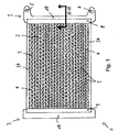
- a view of a heat exchanger 1 is shown.
- a plurality of tubes 2 are arranged between two header tubes 3.
- the two header pipes 3 are connected to one another at the top and bottom with a connecting flange 26.
- Corrugated fins 4, which connect the tubes 2 both mechanically and thermally, are formed between the tubes 2.
- the corrugated fins 4 serve to enlarge the surface area of the heat exchanger 1 and thereby increase the heat transfer.
- the manifold 3 shown on the right has an inlet opening 5 and an outlet opening 6.
- the heat exchanger 1 is used in a motor vehicle to give off the heat of the cooling liquid to the environment.
- Cooling liquid thus flows through the inlet opening 5 into the heat exchanger 1 and it flows out again in a cooled state through the outlet opening 6.
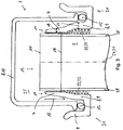
- the two collecting pipes 3 each consist of a base 9 made of aluminum and each a box 10 made of plastic, in which the inlet opening 5 and the outlet opening 6 are also formed.
- the bottom 9 and the box 10 enclose a flow space 25 for the cooling liquid ( Fig. 2 and 3 ).
- the box 10 is essentially U-shaped in cross section.
- the bottom 9 is provided with a channel 21 at each end in cross section.
- a seal 12 is arranged in the channel 21.
- the seal 12, an elastic part, serves to connect the bottom 9 to the box 10 in a liquid-tight manner.
- An opening wall 14 of the collecting pipe 3 or of the bottom 9 has been shaped into a passage 7.
- the end of the passage 7 ends in the flow space 25 of the collecting pipe 3.
- the passage 7 thus represents the former opening wall 14 of the base 9 ( Fig. 5 ), which has been formed into the passage 7.
- an impression 27 is first applied in a partial area 20 of the wall 8 of the base 9, ie the opening wall 14, by means of a stamp.
- the sub-area 20 corresponds to a section of the wall 8 that is reshaped to form the passage 7.
- the sub-area 20 is in Fig. 4 that portion of the wall 8 which is formed within the dashed line.
- the values 27 are in Fig. 4 also shown in dashed lines.
- the wall 8 is stretched in the partial area 20, which corresponds to the later passage 7, so that the thickness 16 of the passage 7 is less than the thickness 17 of the wall 8 of the base 7 in the non-deformed area, ie outside the sub-area 20 or the thickness 17 of the opening walls 14.
- the opening 13 is produced by means of a piercing tool.
- the wall 8 of the base 9 is bent over within the sub-area 20, so that the in Fig. 2 and 5 Shown shape of the passage 7 results.
- the thickness 17 of the wall 8 of the base 9 is thus greater than the thickness 16 of the passage 9.
- a point 15 is formed at the end of the passage 7 due to the piercing process.
- the tip 15 is essentially triangular in cross section.
- the thickness of the passage 7 in front of the tip 15 is, for example, 20 to 30% of the thickness 17 of the wall 8 of the base 9 before the deformation.
- connection 22 designed as a soldered connection 23 ( Fig. 2 ).
- the plane of the drawing is parallel to a plane of a broad side wall of the tube 2 and perpendicular to a plane of a narrow side wall 28 of the tube 2.
- the length 18 of the passage 7 is greater than half the minimum diameter 29 of the opening 13, because the wall 8 of the bottom 9 has been stretched in the sub-area 20 during the formation of the passage 7.
- the opening 13 is also rectangular in shape corresponding to the rectangular cross-section of the tube 2.
- the length 18 of the passage 7 is greater than half the width of the opening 13.
- a diameter 19 of the opening 13 is slightly smaller than a corresponding outer diameter (not shown) of the pipe 2.
- the distance between the passage 7 and the pipe 2 is, for example, in the range between 0.2 and 1 mm, so that the brazing material can penetrate into this gap by capillary action. If the tubes 2 and the base 9 are plated with a solder and the soldered connection is made in a soldering furnace, no spacing is required.
- the thickness of the passage 7 decreases steadily from the beginning of the passage 7 on the wall 8 of the base 9 or of the collecting pipe 3 to the end of the passage 7 at the tip 15 of the passage 7. This results from the production of the passage 7.
- the middle area is stretched more than the edge area of the sub-area 20 near the non-deformed or stretched wall 8 of the base 9 the passage 7 is also stretched when it is pierced and this stretching is also greater here in the region of the end of the passage 7 than at the beginning of the passage 7.
- Fig. 5 a partial longitudinal section of the bottom 9 after the penetration of the sub-area 20 is shown.
- the passages 7 are formed parallel to an axis 24 of the opening 13.
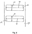
- Fig. 6 is a view of the openings 13 shown in the direction of an axis of the openings.
- the openings 13 are rectangular and have a minimum diameter 29 and a maximum diameter 30.
- a second embodiment of the manifold 3 of the heat exchanger 1 is shown.
- the bottom 9 is designed in such a way that there is a small distance in the range between 0 and 2 mm between an outside of the channel 21 and the pipe 2.
- this gap with a thickness between 0 and 2 mm there is a material connection 22 designed as a soldered connection 23.
- the thickness of this gap between the outside of the channel 21 and the outside of the pipe 2 is preferably 0.2 to 0.8 mm, so that the soldering material for the soldered connection 23 can expand capillary in the gap and rise.
- the pipe 2 is thus advantageously also connected to the base 9 and thereby the strength of the mechanical connection between the pipe 2 and the base 9 or the collecting pipe 3 is increased.
- Mechanical stress which results in particular from thermal deformations of the heat exchanger 1, can thereby be better absorbed. Damage to the heat exchanger 1 resulting from damage to the connection between the pipe 2 and the header pipe 3 can thereby be reduced.
- the heat exchanger 1 according to the invention is associated with considerable advantages.
- the passage 7 is stretched in such a way that the length 18 of the passage 7 is stretched in the direction of the axis 24 of the opening 13.
- This increases the contact surface between the pipe 2 and the passage 7, formed as a soldered connection 23.
- the mechanical stresses on the connection between the pipe 2 and the passage 7, which result in particular from thermal deformations of the heat exchanger 1, can thereby be absorbed more easily. Damage to the heat exchanger 1 resulting therefrom, for example leaks at the connection between the tube 2 and the passage 7, can thereby be significantly reduced.
- the larger contact surface thus leads to a larger contact surface and support surface of the pipe 2 on the passage 7. This can significantly increase the reliability of a heat exchanger 1 according to the invention and a motor vehicle air conditioning system according to the invention.
Landscapes
- Engineering & Computer Science (AREA)
- Physics & Mathematics (AREA)
- Thermal Sciences (AREA)
- Mechanical Engineering (AREA)
- General Engineering & Computer Science (AREA)
- Heat-Exchange Devices With Radiators And Conduit Assemblies (AREA)
- Details Of Heat-Exchange And Heat-Transfer (AREA)
- Air-Conditioning For Vehicles (AREA)
Claims (6)
- Echangeur de chaleur (1), en particulier échangeur de chaleur (1) pour un véhicule automobile, comprenant :- une multiplicité de tubes (2),- au moins un tube collecteur (3) ayant un fond (9) qui présente une paroi (8), où des ouvertures (13) sont prévues dans la paroi (8), où des passages (7) sont formés en faisant saillie par rapport à la paroi (8), dans la direction axiale des ouvertures (13), où les tubes (2), dans la zone d'une extrémité (11) des tubes (2), sont disposés partiellement sur les passages (7), et il y a une liaison étanche aux fluides entre les passages (7) et les tubes (2),- au moins une ouverture d'entrée (5) pour faire entrer un fluide, et- au moins une ouverture de sortie (6) pour faire sortir le fluide, où l'épaisseur (16) des passages (7), en particulier dans la zone des ouvertures (13), est inférieure à l'épaisseur (17) de la paroi (8) du tube collecteur (3), et l'épaisseur (16) des passages (7) diminue, de préférence de façon constante, à partir du début des passages (7) situé sur la paroi (8) du tube collecteur (3) jusqu'à une extrémité des passages (7),caractérisé en ce que l'épaisseur (16) des passages (7), à partir d'un début situé sur le fond (9) jusqu'à une pointe (15) des passages (7), est, en particulier dans la zone des ouvertures (13), égale à au moins 10 % de l'épaisseur (17) de la paroi (8) du tube collecteur (3), où la longueur de la pointe (15) des passages (7) est, en particulier dans la zone des ouvertures (13), égale à au moins 10 % de l'épaisseur de la paroi (8) du tube collecteur (3), et où l'épaisseur (16) des passages (7), à partir d'un début situé sur le fond (9) allant jusqu'à 0,8 fois la longueur totale du passage (7) placé en amont de la pointe (15), est, en particulier dans la zone des ouvertures (13), inférieure à 0,9 fois l'épaisseur de la paroi (8) du tube collecteur (3).
- Echangeur de chaleur selon la revendication 1, caractérisé en ce que la longueur maximale des passages (7) est supérieure à la moitié, en particulier de 1,1 fois à 3 fois supérieure à la moitié du diamètre minimal (29) des ouvertures (13).
- Procédé de fabrication d'un échangeur de chaleur (1) selon l'une ou plusieurs des revendications précédentes, ledit procédé comprenant les étapes consistant :- à réaliser des tubes (2),- à réaliser au moins partiellement au moins un tube collecteur (3) ayant une paroi (8),- à percer une zone partielle (20) de la paroi (8) du tube collecteur (3) au moins au nombre de un, pour former des ouvertures (13) ayant des passages (7),- à introduire les tubes (2) dans les ouvertures (13), et- à assurer la liaison, étanche aux fluides, des tubes (2) avec les passages (7),caractérisé en ce que
la paroi (8) du tube collecteur (3) au moins au nombre de un, avant la percée dans les zones partielles (20), est étirée pour former des parties arquées (27), de sorte que l'épaisseur (16) des passages (7) est, avant l'étirage dans les zones partielles (20), inférieure à l'épaisseur (17) de la paroi (8) du tube collecteur (3). - Procédé selon la revendication 3, caractérisé en ce que l'étirage de la paroi (8) du tube collecteur (3) au moins au nombre de un effectué dans les zones partielles (20) est réalisé en une seule opération particulière, avant la percée.
- Procédé selon l'une ou plusieurs des revendications 3 ou 4, caractérisé en ce que l'étirage de la paroi (8) du tube collecteur (3) au moins au nombre de un effectué dans les zones partielles (20) est réalisé avec un autre outil que celui utilisé pour la percée et / ou aucune matière n'est enlevée, par exemple par estampage, de la paroi (8).
- Système de climatisation d'un véhicule automobile, caractérisé en ce que le système de climatisation du véhicule automobile comprend un échangeur de chaleur selon l'une ou plusieurs des revendications 1 ou 2.
Applications Claiming Priority (3)
| Application Number | Priority Date | Filing Date | Title |
|---|---|---|---|
| DE102008027551 | 2008-06-10 | ||
| DE102008052590 | 2008-10-21 | ||
| PCT/EP2009/003847 WO2009149838A1 (fr) | 2008-06-10 | 2009-05-29 | Échangeur thermique |
Publications (2)
| Publication Number | Publication Date |
|---|---|
| EP2294350A1 EP2294350A1 (fr) | 2011-03-16 |
| EP2294350B1 true EP2294350B1 (fr) | 2021-03-31 |
Family
ID=41059312
Family Applications (1)
| Application Number | Title | Priority Date | Filing Date |
|---|---|---|---|
| EP09761401.0A Active EP2294350B1 (fr) | 2008-06-10 | 2009-05-29 | Échangeur de chaleur |
Country Status (8)
| Country | Link |
|---|---|
| US (1) | US20110139424A1 (fr) |
| EP (1) | EP2294350B1 (fr) |
| JP (1) | JP2011523998A (fr) |
| CN (1) | CN102057245A (fr) |
| BR (1) | BRPI0915002A2 (fr) |
| DE (1) | DE102009022983A1 (fr) |
| RU (1) | RU2010153607A (fr) |
| WO (1) | WO2009149838A1 (fr) |
Families Citing this family (14)
| Publication number | Priority date | Publication date | Assignee | Title |
|---|---|---|---|---|
| DE102010003631A1 (de) * | 2010-04-01 | 2011-10-06 | Behr Gmbh & Co. Kg | Verfahren zur Herstellung eines Metallteils |
| DE102011075071A1 (de) | 2011-05-02 | 2012-11-08 | Behr Gmbh & Co. Kg | Wärmetauscher, insbesondere Ladeluftkühler |
| DE102011076225A1 (de) | 2011-05-20 | 2012-11-22 | Behr Gmbh & Co. Kg | Wärmetauscher |
| JP6197338B2 (ja) * | 2012-04-04 | 2017-09-20 | 株式会社デンソー | 熱交換器 |
| DE102012217870A1 (de) * | 2012-09-28 | 2014-04-17 | Behr Gmbh & Co. Kg | Wärmeübertrager |
| US9593891B2 (en) | 2012-09-28 | 2017-03-14 | Mahle International Gmbh | Heat exchanger |
| CN103033072B (zh) * | 2012-12-26 | 2014-06-11 | 陕西宝成航空仪表有限责任公司 | 翅管式换热器 |
| DE112014001333T5 (de) * | 2013-03-12 | 2015-11-26 | Lockheed Martin Corporation | Rührreibschweissverfahren an Rohrendenfugen und ein dadurch gefertigtes Produkt |
| DE102013208424A1 (de) * | 2013-05-07 | 2014-11-13 | Behr Gmbh & Co. Kg | Boden für einen Wärmetauscher, insbesondere für ein Kraftfahrzeug und Verfahren zur Herstellung des Bodens |
| DE102013208425A1 (de) * | 2013-05-07 | 2014-11-13 | Behr Gmbh & Co. Kg | Wärmetauscher, insbesondere für ein Kraftfahrzeug |
| US10371464B2 (en) | 2015-07-07 | 2019-08-06 | Mahle International Gmbh | Tube header for heat exchanger |
| JP6547576B2 (ja) * | 2015-10-15 | 2019-07-24 | 株式会社デンソー | 熱交換器 |
| CN108959822B (zh) * | 2018-08-01 | 2023-06-06 | 中国航空工业集团公司沈阳飞机设计研究所 | 一种减小热结构内部热应力作用的设计方法 |
| FR3102318B1 (fr) * | 2019-10-17 | 2022-12-30 | Dualsun | installation comportant une connectique pour le raccordement fluidique d’un échangeur thermique d’au moins un panneau solaire hybride |
Family Cites Families (9)
| Publication number | Priority date | Publication date | Assignee | Title |
|---|---|---|---|---|
| US4150556A (en) * | 1978-02-27 | 1979-04-24 | Mccord Corporation | Radiator tank headsheet and method |
| DD211225A3 (de) | 1982-05-17 | 1984-07-04 | Umform & Plastverarb Fz | Boden fuer den tank eines rohrwaermetauschers und werkzeug zu dessen herstellung |
| DE4129573C2 (de) * | 1991-09-06 | 1997-10-23 | Behr Gmbh & Co | Wärmetauscher |
| FR2739680B1 (fr) | 1995-10-06 | 1997-12-05 | Valeo Thermique Moteur Sa | Echangeur de chaleur, en particulier radiateur d'air de suralimentation pour vehicule automobile |
| FR2752930B1 (fr) * | 1996-08-29 | 1998-11-13 | Valeo Thermique Moteur Sa | Collecteur a collets, a base d'aluminium, pour echangeur de chaleur, notamment de vehicule automobile |
| DE19844848A1 (de) | 1998-09-30 | 2000-04-06 | Modine Mfg Co | Wärmetauscher |
| US6446337B1 (en) * | 2000-11-28 | 2002-09-10 | S & Z Tool & Die Co., Inc. | Formation of tube slots in clad aluminum materials |
| DE10343239B4 (de) * | 2003-09-17 | 2021-09-09 | Mahle International Gmbh | Wärmeübertrager |
| US7413006B2 (en) * | 2006-04-06 | 2008-08-19 | Modine Manufacturing Company | Header plate for use in a heat exchanger |
-
2009
- 2009-05-28 DE DE102009022983A patent/DE102009022983A1/de not_active Withdrawn
- 2009-05-29 CN CN2009801219901A patent/CN102057245A/zh active Pending
- 2009-05-29 WO PCT/EP2009/003847 patent/WO2009149838A1/fr not_active Ceased
- 2009-05-29 BR BRPI0915002A patent/BRPI0915002A2/pt not_active IP Right Cessation
- 2009-05-29 EP EP09761401.0A patent/EP2294350B1/fr active Active
- 2009-05-29 RU RU2010153607/06A patent/RU2010153607A/ru unknown
- 2009-05-29 JP JP2011512861A patent/JP2011523998A/ja active Pending
-
2010
- 2010-12-10 US US12/965,461 patent/US20110139424A1/en not_active Abandoned
Non-Patent Citations (1)
| Title |
|---|
| None * |
Also Published As
| Publication number | Publication date |
|---|---|
| DE102009022983A1 (de) | 2009-12-17 |
| EP2294350A1 (fr) | 2011-03-16 |
| RU2010153607A (ru) | 2012-07-20 |
| JP2011523998A (ja) | 2011-08-25 |
| BRPI0915002A2 (pt) | 2015-10-27 |
| WO2009149838A1 (fr) | 2009-12-17 |
| CN102057245A (zh) | 2011-05-11 |
| US20110139424A1 (en) | 2011-06-16 |
Similar Documents
| Publication | Publication Date | Title |
|---|---|---|
| EP2294350A1 (fr) | Échangeur thermique | |
| EP1204495B1 (fr) | Echangeur de chaleur | |
| DE102004045018B4 (de) | Verfahren zur Herstellung eines flachen Rohres für einen Wärmetauscher eines Kraftfahrzeugs, flaches Rohr, Verfahren zur Herstellung eines Wärmetauschers und Wärmetauscher | |
| DE69804007T2 (de) | Verfahren zum zusammensetzen von wärmetauscher | |
| DE4404837A1 (de) | Rippe für Wärmetauscher | |
| DE69708730T2 (de) | Wärmetauscher und Verfahren zu seiner Herstellung | |
| DE102007028792A1 (de) | Wärmeaustauscher | |
| EP0387678A1 (fr) | Echangeur de chaleur et procédé pour la fixation étanche des éléments d'échange dans une plaque d'extrémité | |
| EP2710319B1 (fr) | Échangeur de chaleur | |
| DE69600309T2 (de) | Flachrohr für einen wärmetauscher | |
| DE3937463C2 (de) | Wärmeaustauscher, bestehend aus wenigstens einer an dessen Seitenflächen angebrachten Seitenwand, insbesondere ein Kühler | |
| EP2984420B1 (fr) | Appareil frigorifique muni d'un évaporateur | |
| EP2771636B1 (fr) | Échangeur de chaleur | |
| DE102018111585A1 (de) | Vorrichtung zur Wärmeübertragung sowie Verfahren zum Herstellen der Vorrichtung | |
| DE19911334A1 (de) | Sammelrohr für einen Wärmeübertrager und Herstellungsverfahren hierfür | |
| DE102009034303A1 (de) | Wärmeübertrager | |
| EP2029953A1 (fr) | Échangeur thermique, notamment refroidisseur d'air de suralimentation, à fond tubulaire renforcé | |
| DE102006002932B4 (de) | Wärmetauscher und Herstellungsverfahren für Wärmetauscher | |
| DE69721101T2 (de) | Verflüssiger für Klimaanlagen von Fahrzeugen | |
| WO2014180865A1 (fr) | Fond d'un échangeur de chaleur, en particulier pour véhicule automobile, et procédé pour le fabriquer | |
| DE69903241T2 (de) | Wärmetauscher, insbesondere verflüssiger für kraftfahrzeug und verfahren zu dessen herstellung | |
| WO2003098142A1 (fr) | Echangeur thermique et son procede de production | |
| DE10241635A1 (de) | Flachrohr-Wärmeübertrager sowie Herstellungsverfahren hierfür | |
| EP1771697B1 (fr) | Echangeur thermique, boite destinee a recevoir un fluide pour un echangeur thermique, et procede de production de cette boite | |
| EP1866590B1 (fr) | Echangeur thermique, notamment condenseur pour systeme de climatisation |
Legal Events
| Date | Code | Title | Description |
|---|---|---|---|
| PUAI | Public reference made under article 153(3) epc to a published international application that has entered the european phase |
Free format text: ORIGINAL CODE: 0009012 |
|
| 17P | Request for examination filed |
Effective date: 20110110 |
|
| AK | Designated contracting states |
Kind code of ref document: A1 Designated state(s): AT BE BG CH CY CZ DE DK EE ES FI FR GB GR HR HU IE IS IT LI LT LU LV MC MK MT NL NO PL PT RO SE SI SK TR |
|
| AX | Request for extension of the european patent |
Extension state: AL BA RS |
|
| DAX | Request for extension of the european patent (deleted) | ||
| 17Q | First examination report despatched |
Effective date: 20141211 |
|
| RAP1 | Party data changed (applicant data changed or rights of an application transferred) |
Owner name: MAHLE BEHR GMBH & CO. KG |
|
| STAA | Information on the status of an ep patent application or granted ep patent |
Free format text: STATUS: EXAMINATION IS IN PROGRESS |
|
| GRAP | Despatch of communication of intention to grant a patent |
Free format text: ORIGINAL CODE: EPIDOSNIGR1 |
|
| STAA | Information on the status of an ep patent application or granted ep patent |
Free format text: STATUS: GRANT OF PATENT IS INTENDED |
|
| INTG | Intention to grant announced |
Effective date: 20201021 |
|
| GRAJ | Information related to disapproval of communication of intention to grant by the applicant or resumption of examination proceedings by the epo deleted |
Free format text: ORIGINAL CODE: EPIDOSDIGR1 |
|
| STAA | Information on the status of an ep patent application or granted ep patent |
Free format text: STATUS: EXAMINATION IS IN PROGRESS |
|
| GRAS | Grant fee paid |
Free format text: ORIGINAL CODE: EPIDOSNIGR3 |
|
| STAA | Information on the status of an ep patent application or granted ep patent |
Free format text: STATUS: GRANT OF PATENT IS INTENDED |
|
| INTC | Intention to grant announced (deleted) | ||
| GRAP | Despatch of communication of intention to grant a patent |
Free format text: ORIGINAL CODE: EPIDOSNIGR1 |
|
| GRAA | (expected) grant |
Free format text: ORIGINAL CODE: 0009210 |
|
| STAA | Information on the status of an ep patent application or granted ep patent |
Free format text: STATUS: THE PATENT HAS BEEN GRANTED |
|
| INTG | Intention to grant announced |
Effective date: 20210202 |
|
| AK | Designated contracting states |
Kind code of ref document: B1 Designated state(s): AT BE BG CH CY CZ DE DK EE ES FI FR GB GR HR HU IE IS IT LI LT LU LV MC MK MT NL NO PL PT RO SE SI SK TR |
|
| REG | Reference to a national code |
Ref country code: GB Ref legal event code: FG4D Free format text: NOT ENGLISH Ref country code: CH Ref legal event code: EP |
|
| REG | Reference to a national code |
Ref country code: AT Ref legal event code: REF Ref document number: 1377398 Country of ref document: AT Kind code of ref document: T Effective date: 20210415 Ref country code: DE Ref legal event code: R096 Ref document number: 502009016342 Country of ref document: DE |
|
| REG | Reference to a national code |
Ref country code: IE Ref legal event code: FG4D Free format text: LANGUAGE OF EP DOCUMENT: GERMAN |
|
| REG | Reference to a national code |
Ref country code: LT Ref legal event code: MG9D |
|
| PG25 | Lapsed in a contracting state [announced via postgrant information from national office to epo] |
Ref country code: HR Free format text: LAPSE BECAUSE OF FAILURE TO SUBMIT A TRANSLATION OF THE DESCRIPTION OR TO PAY THE FEE WITHIN THE PRESCRIBED TIME-LIMIT Effective date: 20210331 Ref country code: FI Free format text: LAPSE BECAUSE OF FAILURE TO SUBMIT A TRANSLATION OF THE DESCRIPTION OR TO PAY THE FEE WITHIN THE PRESCRIBED TIME-LIMIT Effective date: 20210331 Ref country code: BG Free format text: LAPSE BECAUSE OF FAILURE TO SUBMIT A TRANSLATION OF THE DESCRIPTION OR TO PAY THE FEE WITHIN THE PRESCRIBED TIME-LIMIT Effective date: 20210630 Ref country code: NO Free format text: LAPSE BECAUSE OF FAILURE TO SUBMIT A TRANSLATION OF THE DESCRIPTION OR TO PAY THE FEE WITHIN THE PRESCRIBED TIME-LIMIT Effective date: 20210630 |
|
| PG25 | Lapsed in a contracting state [announced via postgrant information from national office to epo] |
Ref country code: SE Free format text: LAPSE BECAUSE OF FAILURE TO SUBMIT A TRANSLATION OF THE DESCRIPTION OR TO PAY THE FEE WITHIN THE PRESCRIBED TIME-LIMIT Effective date: 20210331 Ref country code: LV Free format text: LAPSE BECAUSE OF FAILURE TO SUBMIT A TRANSLATION OF THE DESCRIPTION OR TO PAY THE FEE WITHIN THE PRESCRIBED TIME-LIMIT Effective date: 20210331 |
|
| REG | Reference to a national code |
Ref country code: NL Ref legal event code: MP Effective date: 20210331 |
|
| PG25 | Lapsed in a contracting state [announced via postgrant information from national office to epo] |
Ref country code: EE Free format text: LAPSE BECAUSE OF FAILURE TO SUBMIT A TRANSLATION OF THE DESCRIPTION OR TO PAY THE FEE WITHIN THE PRESCRIBED TIME-LIMIT Effective date: 20210331 Ref country code: CZ Free format text: LAPSE BECAUSE OF FAILURE TO SUBMIT A TRANSLATION OF THE DESCRIPTION OR TO PAY THE FEE WITHIN THE PRESCRIBED TIME-LIMIT Effective date: 20210331 Ref country code: NL Free format text: LAPSE BECAUSE OF FAILURE TO SUBMIT A TRANSLATION OF THE DESCRIPTION OR TO PAY THE FEE WITHIN THE PRESCRIBED TIME-LIMIT Effective date: 20210331 Ref country code: LT Free format text: LAPSE BECAUSE OF FAILURE TO SUBMIT A TRANSLATION OF THE DESCRIPTION OR TO PAY THE FEE WITHIN THE PRESCRIBED TIME-LIMIT Effective date: 20210331 |
|
| PG25 | Lapsed in a contracting state [announced via postgrant information from national office to epo] |
Ref country code: IS Free format text: LAPSE BECAUSE OF FAILURE TO SUBMIT A TRANSLATION OF THE DESCRIPTION OR TO PAY THE FEE WITHIN THE PRESCRIBED TIME-LIMIT Effective date: 20210731 Ref country code: RO Free format text: LAPSE BECAUSE OF FAILURE TO SUBMIT A TRANSLATION OF THE DESCRIPTION OR TO PAY THE FEE WITHIN THE PRESCRIBED TIME-LIMIT Effective date: 20210331 Ref country code: PL Free format text: LAPSE BECAUSE OF FAILURE TO SUBMIT A TRANSLATION OF THE DESCRIPTION OR TO PAY THE FEE WITHIN THE PRESCRIBED TIME-LIMIT Effective date: 20210331 Ref country code: PT Free format text: LAPSE BECAUSE OF FAILURE TO SUBMIT A TRANSLATION OF THE DESCRIPTION OR TO PAY THE FEE WITHIN THE PRESCRIBED TIME-LIMIT Effective date: 20210802 Ref country code: SK Free format text: LAPSE BECAUSE OF FAILURE TO SUBMIT A TRANSLATION OF THE DESCRIPTION OR TO PAY THE FEE WITHIN THE PRESCRIBED TIME-LIMIT Effective date: 20210331 Ref country code: ES Free format text: LAPSE BECAUSE OF FAILURE TO SUBMIT A TRANSLATION OF THE DESCRIPTION OR TO PAY THE FEE WITHIN THE PRESCRIBED TIME-LIMIT Effective date: 20210331 |
|
| REG | Reference to a national code |
Ref country code: CH Ref legal event code: PL |
|
| REG | Reference to a national code |
Ref country code: DE Ref legal event code: R097 Ref document number: 502009016342 Country of ref document: DE |
|
| PG25 | Lapsed in a contracting state [announced via postgrant information from national office to epo] |
Ref country code: DK Free format text: LAPSE BECAUSE OF FAILURE TO SUBMIT A TRANSLATION OF THE DESCRIPTION OR TO PAY THE FEE WITHIN THE PRESCRIBED TIME-LIMIT Effective date: 20210331 Ref country code: CH Free format text: LAPSE BECAUSE OF NON-PAYMENT OF DUE FEES Effective date: 20210531 Ref country code: MC Free format text: LAPSE BECAUSE OF FAILURE TO SUBMIT A TRANSLATION OF THE DESCRIPTION OR TO PAY THE FEE WITHIN THE PRESCRIBED TIME-LIMIT Effective date: 20210331 Ref country code: LU Free format text: LAPSE BECAUSE OF NON-PAYMENT OF DUE FEES Effective date: 20210529 Ref country code: LI Free format text: LAPSE BECAUSE OF NON-PAYMENT OF DUE FEES Effective date: 20210531 |
|
| PLBE | No opposition filed within time limit |
Free format text: ORIGINAL CODE: 0009261 |
|
| STAA | Information on the status of an ep patent application or granted ep patent |
Free format text: STATUS: NO OPPOSITION FILED WITHIN TIME LIMIT |
|
| REG | Reference to a national code |
Ref country code: BE Ref legal event code: MM Effective date: 20210531 |
|
| GBPC | Gb: european patent ceased through non-payment of renewal fee |
Effective date: 20210630 |
|
| 26N | No opposition filed |
Effective date: 20220104 |
|
| PG25 | Lapsed in a contracting state [announced via postgrant information from national office to epo] |
Ref country code: IE Free format text: LAPSE BECAUSE OF NON-PAYMENT OF DUE FEES Effective date: 20210529 Ref country code: GB Free format text: LAPSE BECAUSE OF NON-PAYMENT OF DUE FEES Effective date: 20210630 |
|
| PG25 | Lapsed in a contracting state [announced via postgrant information from national office to epo] |
Ref country code: IS Free format text: LAPSE BECAUSE OF FAILURE TO SUBMIT A TRANSLATION OF THE DESCRIPTION OR TO PAY THE FEE WITHIN THE PRESCRIBED TIME-LIMIT Effective date: 20210731 Ref country code: FR Free format text: LAPSE BECAUSE OF NON-PAYMENT OF DUE FEES Effective date: 20210531 |
|
| REG | Reference to a national code |
Ref country code: AT Ref legal event code: MM01 Ref document number: 1377398 Country of ref document: AT Kind code of ref document: T Effective date: 20210529 |
|
| PG25 | Lapsed in a contracting state [announced via postgrant information from national office to epo] |
Ref country code: IT Free format text: LAPSE BECAUSE OF FAILURE TO SUBMIT A TRANSLATION OF THE DESCRIPTION OR TO PAY THE FEE WITHIN THE PRESCRIBED TIME-LIMIT Effective date: 20210331 Ref country code: BE Free format text: LAPSE BECAUSE OF NON-PAYMENT OF DUE FEES Effective date: 20210531 |
|
| PG25 | Lapsed in a contracting state [announced via postgrant information from national office to epo] |
Ref country code: AT Free format text: LAPSE BECAUSE OF NON-PAYMENT OF DUE FEES Effective date: 20210529 |
|
| PG25 | Lapsed in a contracting state [announced via postgrant information from national office to epo] |
Ref country code: HU Free format text: LAPSE BECAUSE OF FAILURE TO SUBMIT A TRANSLATION OF THE DESCRIPTION OR TO PAY THE FEE WITHIN THE PRESCRIBED TIME-LIMIT; INVALID AB INITIO Effective date: 20090529 Ref country code: CY Free format text: LAPSE BECAUSE OF FAILURE TO SUBMIT A TRANSLATION OF THE DESCRIPTION OR TO PAY THE FEE WITHIN THE PRESCRIBED TIME-LIMIT Effective date: 20210331 |
|
| PG25 | Lapsed in a contracting state [announced via postgrant information from national office to epo] |
Ref country code: GR Free format text: LAPSE BECAUSE OF FAILURE TO SUBMIT A TRANSLATION OF THE DESCRIPTION OR TO PAY THE FEE WITHIN THE PRESCRIBED TIME-LIMIT Effective date: 20210331 |
|
| PG25 | Lapsed in a contracting state [announced via postgrant information from national office to epo] |
Ref country code: MK Free format text: LAPSE BECAUSE OF FAILURE TO SUBMIT A TRANSLATION OF THE DESCRIPTION OR TO PAY THE FEE WITHIN THE PRESCRIBED TIME-LIMIT Effective date: 20210331 |
|
| P01 | Opt-out of the competence of the unified patent court (upc) registered |
Effective date: 20240521 |
|
| PG25 | Lapsed in a contracting state [announced via postgrant information from national office to epo] |
Ref country code: TR Free format text: LAPSE BECAUSE OF FAILURE TO SUBMIT A TRANSLATION OF THE DESCRIPTION OR TO PAY THE FEE WITHIN THE PRESCRIBED TIME-LIMIT Effective date: 20210331 |
|
| PG25 | Lapsed in a contracting state [announced via postgrant information from national office to epo] |
Ref country code: MT Free format text: LAPSE BECAUSE OF FAILURE TO SUBMIT A TRANSLATION OF THE DESCRIPTION OR TO PAY THE FEE WITHIN THE PRESCRIBED TIME-LIMIT Effective date: 20210331 |
|
| PGFP | Annual fee paid to national office [announced via postgrant information from national office to epo] |
Ref country code: DE Payment date: 20250521 Year of fee payment: 17 |