EP2294491B1 - Ensemble de réaction et séparateur d écoulement - Google Patents
Ensemble de réaction et séparateur d écoulement Download PDFInfo
- Publication number
- EP2294491B1 EP2294491B1 EP09755071.9A EP09755071A EP2294491B1 EP 2294491 B1 EP2294491 B1 EP 2294491B1 EP 09755071 A EP09755071 A EP 09755071A EP 2294491 B1 EP2294491 B1 EP 2294491B1
- Authority
- EP
- European Patent Office
- Prior art keywords
- capillary
- flow
- unit
- fluid
- reaction
- Prior art date
- Legal status (The legal status is an assumption and is not a legal conclusion. Google has not performed a legal analysis and makes no representation as to the accuracy of the status listed.)
- Active
Links
Images


Classifications
-
- G—PHYSICS
- G05—CONTROLLING; REGULATING
- G05D—SYSTEMS FOR CONTROLLING OR REGULATING NON-ELECTRIC VARIABLES
- G05D7/00—Control of flow
- G05D7/06—Control of flow characterised by the use of electric means
- G05D7/0617—Control of flow characterised by the use of electric means specially adapted for fluid materials
- G05D7/0629—Control of flow characterised by the use of electric means specially adapted for fluid materials characterised by the type of regulator means
- G05D7/0635—Control of flow characterised by the use of electric means specially adapted for fluid materials characterised by the type of regulator means by action on throttling means
-
- B—PERFORMING OPERATIONS; TRANSPORTING
- B01—PHYSICAL OR CHEMICAL PROCESSES OR APPARATUS IN GENERAL
- B01J—CHEMICAL OR PHYSICAL PROCESSES, e.g. CATALYSIS OR COLLOID CHEMISTRY; THEIR RELEVANT APPARATUS
- B01J19/00—Chemical, physical or physico-chemical processes in general; Their relevant apparatus
- B01J19/0046—Sequential or parallel reactions, e.g. for the synthesis of polypeptides or polynucleotides; Apparatus and devices for combinatorial chemistry or for making molecular arrays
-
- G—PHYSICS
- G05—CONTROLLING; REGULATING
- G05D—SYSTEMS FOR CONTROLLING OR REGULATING NON-ELECTRIC VARIABLES
- G05D11/00—Control of flow ratio
- G05D11/02—Controlling ratio of two or more flows of fluid or fluent material
- G05D11/13—Controlling ratio of two or more flows of fluid or fluent material characterised by the use of electric means
- G05D11/131—Controlling ratio of two or more flows of fluid or fluent material characterised by the use of electric means by measuring the values related to the quantity of the individual components
- G05D11/132—Controlling ratio of two or more flows of fluid or fluent material characterised by the use of electric means by measuring the values related to the quantity of the individual components by controlling the flow of the individual components
-
- B—PERFORMING OPERATIONS; TRANSPORTING
- B01—PHYSICAL OR CHEMICAL PROCESSES OR APPARATUS IN GENERAL
- B01J—CHEMICAL OR PHYSICAL PROCESSES, e.g. CATALYSIS OR COLLOID CHEMISTRY; THEIR RELEVANT APPARATUS
- B01J2219/00—Chemical, physical or physico-chemical processes in general; Their relevant apparatus
- B01J2219/00274—Sequential or parallel reactions; Apparatus and devices for combinatorial chemistry or for making arrays; Chemical library technology
- B01J2219/00277—Apparatus
- B01J2219/00279—Features relating to reactor vessels
- B01J2219/00281—Individual reactor vessels
- B01J2219/00286—Reactor vessels with top and bottom openings
-
- B—PERFORMING OPERATIONS; TRANSPORTING
- B01—PHYSICAL OR CHEMICAL PROCESSES OR APPARATUS IN GENERAL
- B01J—CHEMICAL OR PHYSICAL PROCESSES, e.g. CATALYSIS OR COLLOID CHEMISTRY; THEIR RELEVANT APPARATUS
- B01J2219/00—Chemical, physical or physico-chemical processes in general; Their relevant apparatus
- B01J2219/00274—Sequential or parallel reactions; Apparatus and devices for combinatorial chemistry or for making arrays; Chemical library technology
- B01J2219/00277—Apparatus
- B01J2219/00279—Features relating to reactor vessels
- B01J2219/00306—Reactor vessels in a multiple arrangement
-
- B—PERFORMING OPERATIONS; TRANSPORTING
- B01—PHYSICAL OR CHEMICAL PROCESSES OR APPARATUS IN GENERAL
- B01J—CHEMICAL OR PHYSICAL PROCESSES, e.g. CATALYSIS OR COLLOID CHEMISTRY; THEIR RELEVANT APPARATUS
- B01J2219/00—Chemical, physical or physico-chemical processes in general; Their relevant apparatus
- B01J2219/00274—Sequential or parallel reactions; Apparatus and devices for combinatorial chemistry or for making arrays; Chemical library technology
- B01J2219/00277—Apparatus
- B01J2219/00351—Means for dispensing and evacuation of reagents
- B01J2219/00418—Means for dispensing and evacuation of reagents using pressure
-
- B—PERFORMING OPERATIONS; TRANSPORTING
- B01—PHYSICAL OR CHEMICAL PROCESSES OR APPARATUS IN GENERAL
- B01J—CHEMICAL OR PHYSICAL PROCESSES, e.g. CATALYSIS OR COLLOID CHEMISTRY; THEIR RELEVANT APPARATUS
- B01J2219/00—Chemical, physical or physico-chemical processes in general; Their relevant apparatus
- B01J2219/00274—Sequential or parallel reactions; Apparatus and devices for combinatorial chemistry or for making arrays; Chemical library technology
- B01J2219/00583—Features relative to the processes being carried out
- B01J2219/00585—Parallel processes
- B01J2219/00587—High throughput processes
-
- Y—GENERAL TAGGING OF NEW TECHNOLOGICAL DEVELOPMENTS; GENERAL TAGGING OF CROSS-SECTIONAL TECHNOLOGIES SPANNING OVER SEVERAL SECTIONS OF THE IPC; TECHNICAL SUBJECTS COVERED BY FORMER USPC CROSS-REFERENCE ART COLLECTIONS [XRACs] AND DIGESTS
- Y10—TECHNICAL SUBJECTS COVERED BY FORMER USPC
- Y10T—TECHNICAL SUBJECTS COVERED BY FORMER US CLASSIFICATION
- Y10T137/00—Fluid handling
- Y10T137/2496—Self-proportioning or correlating systems
- Y10T137/2514—Self-proportioning flow systems
Definitions
- the invention pertains to a reaction system.
- the invention also pertains to a flow splitter for splitting a primary fluid flow into a plurality of secondary fluid flows for performing experiments.
- reactors in which the experiments take place receive their feed from a single source.
- the reactor feed comes from this single source in a single, primary fluid flow which is then split into a plurality of secondary fluid flows. Each of the secondary fluid flows is then fed to a reactor in which a reaction can take place.
- WO99/64160 discloses that a substantially equal flow distribution over all reactors can be obtained by arranging capillaries upstream of the reaction vessels. WO99/64160 also discloses that by heating a capillary, the viscosity of the fluid flowing through the capillary can be influenced, and thereby the flow rate of the fluid through the capillary can be influenced.
- the generally applied way of adaptation of the flow resistance of a capillary is by changing its length, usually by cutting off small lengths of the capillary until the desired flow rate is obtained. This is a painstaking process as it is hard to make the cuts accurately enough and often too much is cut off, which means you have to start all over again. To do this right requires a lot of practice of the lab personnel involved.
- the flow rates in all capillaries of the system change when the flow resistance of one capillary in the system is changed, because the ratio between the flow resistance of the different capillaries determines the distribution ratio of the primary flow over the secondary flows. So, if one capillary in the system has to be adapted to obtain the desired flow rate, all other capillaries have to be adapted as well.
- the object of the invention is to provide an improved reaction system and an improved flow splitter.
- a primary fluid flow coming from a fluid supply unit is distributed over a plurality of reaction vessels.
- This distribution is achieved by the use of a plurality of capillary units, each being arranged downstream of the fluid supply unit and upstream of one of the reaction vessels.
- the capillary unit comprises a capillary, which has a resistance to fluid flow. The combination of the resistance to fluid flow of the individual capillaries determines in which proportions the primary fluid flow from the fluid supply is distributed over the individual reaction vessels.
- the capillary in the housing of each capillary unit has been prepared beforehand.
- the resistance to fluid flow of the capillary at a reference temperature e.g. room temperature
- a fluid of a known viscosity has been measured and is therewith known. It is not necessary to prepare such a capillary to accurately have a predetermined resistance to fluid flow.
- the heater and/or cooler of a capillary unit is adapted to change the temperature of the capillary of the capillary unit and therewith influences the flow rate of the fluid flow through that capillary.
- the temperature of the capillary affects the flow rate through that capillary in several ways: the viscosity of the fluid in the capillary depends from the temperature, the fluid expands when it is heated and maybe the inner dimensions of the capillary change a bit too because of thermal expansion effects. Both the viscosity of the fluid and the dimensions of the capillary are parameters that determine the flow resistance of the capillary, and therewith the flow rate of the fluid flow through that capillary.
- the heater/cooler of the capillary unit can change the resistance to fluid flow of the capillary of the capillary unit over a certain range.
- the range of fluid flow resistance for which it can be applied is known, either through measurement, through calculations or through a combination thereof.
- the viscosity of the fluid flowing through the capillary units is determined, as well as the ratio to which the primary fluid flow is to be distributed over the reaction vessels. Based on this, for each reaction vessel, a suitable capillary unit is selected. "Suitable" means that the selected capillary unit can provide the desired resistance to fluid flow. It is not necessary that the capillary has precisely the desired resistance to fluid flow at ambient temperature or at the temperature of the fluid flowing through the capillary. It suffices that by using the heater/cooler to heat and/or cool the capillary of the capillary unit, the desired resistance to fluid flow in the capillary can be achieved.
- the selected capillary units can then be arranged in the reaction system according to the invention.
- the flow, resistance of each of the capillaries is tuned by controlling the thermal output of the heater/cooler that is associated with the respective capillary. This can be done either before arranging the capillary unit in the reaction system or afterwards.
- Tuning the flow resistance of the capillaries by using the heater/cooler is a lot simpler than tuning the flow resistance by cutting the capillary to length. It does not require the hand skills of the laboratory personnel. Also, it is possible to reverse your actions: you can both increase and decrease the flow resistance. When cutting the capillary to length, you cannot make the capillary longer again if you cut off too much.
- the capillaries are arranged in capillary units is further advantageous as it makes them easy to exchange and reusable. If each capillary unit is arranged in a cassette, it is even easier to exchange.
- a cassette is a lot easier to handle than a thin and springy capillary.
- the cassette is provided with quick catch connections so that it can easily be put into fluid communication with the fluid supply unit and the reactors.
- the cassette is also provided with electrical connectors so it can easily be connected to the flow adjustment unit (if that is not provided in the cassette as well), to the electrical feed for the heater/cooler and/or the flow sensor, and/or to other control units of the reaction system, for example for the exchange of measurement data.
- the reaction system can be a modular system, in which parts can be easily exchanged for other parts to suit the requirements of different experiments.
- the flow adjustment unit determines the flow rate of the fluid flow, which can be a gas flow, a liquid flow, a combined gas/liquid flow, a flow of gel or any other like flow.
- the flow adjustment unit determines the deviation of the flow rate of the fluid flow from a desired flow rate, and adjusts the flow rate by controlling the heater and/or cooler of the capillary unit.
- the heater and/or cooler changes the temperature of the capillary of the capillary unit and therewith influences the flow rate of the fluid flow through that capillary.
- the temperature of the capillary affects the flow rate through that capillary in several ways: the viscosity of the fluid in the capillary depends from the temperature, the fluid expands when it is heated and maybe the inner dimensions of the capillary change a bit too because of thermal expansion effects. Both the viscosity of the fluid and the dimensions of the capillary are parameters that determine the flow resistance of the capillary, and therewith the flow rate of the fluid flow through that capillary.
- Each capillary unit can have its own flow adjustment unit, or a plurality of capillary units can be controlled by a single flow adjustment unit.
- the flow adjustment unit can be connected to or be part of an overall control system controlling the splitter, or when the splitter is used in a reaction system, of a reaction system control unit that controls the whole reaction system or a part thereof.
- the capillary unit can also be used to compensate the flow distribution over the reaction vessels for pressure differences in the different reaction vessels. It is possible that while the reactions in the reaction vessels take place, a pressure difference starts to build up between amongst the reaction vessels. If that is the case, and nothing would be done, the flow distribution over the reaction vessels would change. However, by changing the resistance to fluid flow of the capillaries by their individual heater and/or cooler, this effect can be compensated so that the flow distribution over the reaction vessels remains the same.
- the capillary unit is at least partly accommodated in a cassette, so that it can be easily connected to other elements of a reaction system, such as a fluid source and/or a reactor. It is possible that the entire capillary unit is enclosed in the cassette, but it is also possible that for example the flow sensor is arranged outside of the cassette.
- the heater comprises a wire having an electrical resistance, which wire is wound around the capillary for supplying heat to said capillary.
- the capillary is arranged, for example wound, around a core, which core is provided with heating and/or cooling means.
- the reaction system according to the invention can be used for gases, liquids, gels, and/or combinations thereof. It is in particular suitable to be used for controlling flows having small flow rates, such as between 1 microliters and 2 ml per minute for the secondary fluid flow if the fluid is a liquid, or less then 100Nml per minute, often less then 50 Nml per minute if the fluid is a gas.
- the reaction system comprises a manifold, which manifold has a manifold inlet for receiving the primary fluid flow, and a plurality of manifold outlets for releasing the plurality of secondary fluid flows.
- the reaction system further comprises a plurality of capillary units, each of the capillary units comprising a unit inlet for receiving a secondary fluid flow from a manifold outlet, a unit outlet for releasing said secondary fluid flow, a capillary, which capillary is arranged between the unit inlet and the unit outlet such that said secondary fluid flow passes through the capillary, a heater and/or a cooler for adjusting the temperature of the capillary and therewith influencing the flow rate of the secondary fluid flow passing through said capillary and a housing for accommodating at least the capillary and heater and/or cooler of said capillary unit, which housing provides thermal insulation of the capillary.
- the capillary unit further comprises a flow sensor that is adapted to measure the flow rate of the fluid flow through the capillary unit.
- the reaction system further comprises a flow adjustment unit for adjusting the flow rates of the secondary fluid flows, which flow adjustment unit comprises a temperature control device for individually controlling each of the heaters and/or coolers of the capillary units.
- the flow rate of each secondary fluid flow is measured by a flow sensor, and based on the measured flow rate, the temperature control unit makes that the heater and/or cooler in the housing of capillary unit to which the measured flow rate pertains heat or cool the capillary in that housing. By changing the capillary temperature, the flow rate of the fluid flow through the capillary is adjusted.
- the thermally insulated housing of the capillary of each capillary unit prevents that the temperature of one capillary influences the temperature of an other capillary that is arranged nearby. This allows accurate control of the temperature of each individual capillary, and therewith accurate control of the flow rate of each individual second fluid flow.
- the capillary within a housing that is provided with thermal insulation, the influence of the temperature of the direct environment of the capillary on the flow rate of the flow through that capillary is decreased.
- a heater and/or a cooler within said housing, the temperature of the capillary can be controlled more directly, which makes that the desired flow rate of the fluid flow can be obtained rapidly.
- the reaction system according to the invention is suitable for obtaining a distribution of the primary fluid flow into secondary fluid flows which have equal flow rates. However, it is also possible to obtain any other desired distribution of flow rates of the secondary fluid flows.
- At least one unit outlet is connected to a reaction vessel. This way, the fluid flow supplied to that reaction vessel can be controlled.
- one or more capillary units are accommodated in a cassette.
- Each cassette can contain one or more capillary units.
- the heater comprises a wire having an electrical resistance, which wire is wound around the capillary for supplying heat to said capillary.
- the capillary is arranged, preferably wound, around a core, which core is provided with heating and/or cooling means.
- the reaction system further comprises an auxiliary channel, which has a resistance to fluid flow that is considerably lower than the resistance to fluid flow in the secondary channels.
- the auxiliary channel is connected to the manifold, which has the effect that the main part of the fluid that enters the manifold leaves the manifold via the auxiliary channel.
- the auxiliary channel can for example take the fluid back to the source from which it came before entering the manifold inlet, to waste or to a separate discharge.
- the effect of the auxiliary channel is that, especially as long as the pressure at the manifold inlet is kept steady, a change in flow rate through one of the capillary units does not or hardly not influence the flow rate through the other capillary units.
- the reaction system further comprises a reaction block for accommodating the reaction vessels, and/or one or more cassettes, each cassette accommodating at least one of the plurality of capillary units of the flow splitter and an enclosure or a frame for receiving at least the reaction block and the one or more cassettes.
- the reactors are flow through reactors.
- the primary fluid flow is split into a plurality of secondary fluid flows, and each of these secondary fluid flows is supplied to a reaction vessel.
- the flow rates of the secondary fluid flows are controlled by the capillary units.
- the capillary units can also be used in reaction systems with a different set-up and/or be arranged at other locations in the reaction system. Some of those reaction systems will be described below.
- the invention further pertains to a reaction system for performing parallel experiments, wherein the fluids come from different fluid sources.
- the fluid sources can for example supply different fluids and/or fluids at a different pressure.
- This reaction system comprises a first fluid supply unit for supplying a first primary fluid flow at a first pressure, and a second fluid supply unit for supplying a second primary fluid flow at a second pressure. Further it comprises a first capillary unit, which is a capillary unit of the same kind as used in the reaction system according to claim 1, which first capillary unit is adapted to receive the first primary fluid flow from the first fluid supply unit.
- a second capillary unit which is a capillary unit of the same kind as used in the reaction system according to claim 1, which second capillary unit is adapted to receive the second primary fluid flow from the second fluid supply unit.
- a first reactor which is in fluid communication with the first capillary unit and a second reactor, which is in fluid communication with the second capillary unit.
- the first capillary unit comprises a flow adjustment unit that is adapted to adjust the flow rate of the first primary fluid flow through the first capillary unit.
- the second capillary unit comprises a flow adjustment unit that is adapted to adjust the flow rate of the second primary fluid flow through the second capillary unit such that a predetermined distribution of flow rates of the first and the second primary fluid flow is obtained.
- the flow adjustment unit of the first capillary unit and the flow adjustment unit of the second capillary unit are separate entities, but it is also possible that they are integrated into a single flow adjustment unit. They can be part of an overall reaction system control unit.
- This reaction system is in particular suitable to obtain a first flow rate (of the first primary fluid flow) and a second flow rate (of the second primary fluid flow) that are in a predetermined proportion to each other, independent of the pressure. For example, despite different pressures, a first and second flow rate that are equal to each other can be obtained.
- the reaction system further comprises a reaction block for accommodating the reaction vessels, one or more cassettes, each cassette accommodating at least one of the plurality of capillary units of the flow splitter and an enclosure for receiving at least the reaction block and the one or more cassettes.
- the reactors are flow through reactors.
- a capillary unit as used in the reaction system of claim 1 can also be used in a back pressure control system for controlling the pressure downstream of a reaction vessel outlet.
- reaction system for performing experiments, which reaction system comprises:
- the principle of the capillary unit as used in the reaction system is used in a back pressure control system for controlling the pressure in a reaction vessel.
- the pressure inside a reaction vessel can be controlled by controlling the pressure downstream of the reaction vessel, advantageously close to the reaction vessel outlet.
- the reaction vessel effluent line is provided with an aperture, through which a portion of the reaction vessel effluent can escape.
- the portion of the reaction vessel effluent that escapes is called the pressure control flow.
- a reactor system for performing parallel experiments comprises a plurality of reaction vessels, each of them being connected to an associated effluent line.
- Each of the effluent lines is provided with an aperture, for releasing a pressure control flow.
- the flow rate of each of the pressure control flows is controlled using the principle of the capillary unit as used in the reaction system.
- a plurality of capillary units, the manifold and the flow adjustment unit are built together to form a flow splitter.
- the components of the flow splitter are arranged together in a cassette that can easily be connected to other components of a reaction system, such as a fluid supply unit, a plurality of reaction vessels and a reaction system control system.
- the flow splitter is designed in such a way that the capillary units are easily exchangeable, so suitable capillary units can be selected for different experiments.
- Fig. 1 shows an embodiment of a capillary unit according to the invention.
- fluid is supplied to a capillary unit 1 by a supply line 10.
- the fluid which can be a gas, a liquid or a combination thereof, enters the capillary unit by the capillary unit inlet 2.
- capillary 4 the fluid flows to capillary unit outlet 3, where it leaves the capillary unit.
- the capillary 4 extends all the way from the capillary unit inlet 2 to the capillary unit outlet 3, but this is not necessary for its functioning.
- the fluid flows away from the capillary unit 1 by discharge line 11.
- Flow sensor 7 measures the flow rate of the fluid flow downstream of the capillary 4.
- the flow sensor 7 can be arranged either outside or inside the housing 6.
- the capillary 4 is arranged in housing 6, which is provided with thermal insulation. Inside the housing a heater and/or cooler 5 is arranged. With this heater and/or cooler 5, the temperature of the capillary can be influenced. The thermal insulation of the housing 6 makes that the temperature of the capillary 4 can be controlled effectively and accurately, because the capillary is shielded from outside thermal influences. In addition, and in case the capillary heated, less heat leaks away from the capillary.
- the heater/cooler 5 is controlled by a temperature control device 8, which can be arranged inside the housing 6, outside the housing 6 or partially inside and partially outside the housing 6.
- POM is a suitable material to be used for the thermal insulation, as it has good thermal insulating properties and is easy to process.
- the flow rate of the fluid flow through the capillary 4 also changes. This is due to a combination of effects.
- the temperature of the capillary 4 rises, so does the temperature of the fluid in the capillary 4. This lowers the viscosity of the fluid and therewith the flow resistance that the fluid flow experiences in the capillary 4. Also, it makes the fluid expand in volume. Both effects make the flow rate downstream of the capillary 4 go up. It is also possible that thermal expansion changes the internal dimensions of the capillary 4, which also changes the flow resistance of the capillary 4.
- the flow rate of the fluid flow through the capillary 4 goes up when the temperature of the capillary 4 is increased.
- different effects will be more important or less important in their contribution to the overall effect.
- the thermal expansion has a more significant influence then for a liquid.
- a higher volumetric flow rate is required to move the same amount of molecules through the capillary. So, if the volumetric flow rate is kept the same, the molecular flow rate will go down. On the other hand, of the molecular flow rate is kept the same, the volumetric flow rate will go up.
- a desired flow rate is set by the flow adjustment unit.
- an accepted band width is determined around the desired flow rate.
- the flow sensor 7 measures the flow rate of the fluid flow leaving the capillary 4. If the flow rate is within the accepted band width, the temperature of the capillary is not changed. If the flow rate is outside the accepted band width, the temperature control device comes into action. If the measured flow rate is lower than the lowest limit of the accepted band width, the temperature control device makes the heater 5 heat up the capillary, for example by raising the temperature by 0.5 °C. After a little while, when the system has had the time to react, the flow sensor 7 again measures the flow rate of the fluid flow. Then again it is determined whether the flow rate is within the accepted band width or not. If the flow rate is still too low, the temperature of the capillary is increased by another step of for example 0.5°C.
- the heater/cooler 5 is controlled by the temperature control device in such a way that the temperature of the capillary is reduced, for example by reducing the temperature by a step of 0.5°C. After a little while, when the system has had the time to react, the flow sensor 7 again measures the flow rate of the fluid flow. Then again it is determined whether the flow rate is within the accepted band width or not. If the flow rate is still too high, the temperature of the capillary is reduced by another step of for example 0.5°C.
- the desired flow rate is obtained by iterative, stepwise changes of the temperature of the capillary 4.
- a PID-control loop can be applied as an alternative to this way of controlling the flow rate.
- the heater/cooler 5 can be realised in many forms. In some embodiments, just a heater of just a cooler suffices. For example, if the capillary is always used at temperatures above room temperature, using only a heater can be fine. In those cases, if the flow rate of the flow through the capillary has to be decreased, the heater 5 just heats the capillary a little less. For example, if the capillary is operated at 80 °C and the flow rate is too high, the heater 5 is then set by the temperature control device to a temperature of 79.5 °C. If the capillary 4 always is cooled, the same principle is used and just a cooler can be applied to obtain the desired effect. So, the heater/cooler 5 can be either a heater or a cooler or a combination of a heater and a cooler.
- the heater/cooler 5 can take many forms. It can be an electrical resistance wire, which produces heat when an electrical current flows through. Such a wire can for example be wound around the capillary.
- the housing 6 can be provided with a heater/cooler channel, through which channel a heated or cooled medium flows. Also, it is possible that the capillary 4 is wound around a core, which core is heated and/or cooled, and which core then in turn heats and/or cools the capillary 4. This is shown in fig. 2
- Fig. 2 shows a further possible embodiment of a capillary unit 1.
- a supply line 10 supplies fluid flow F to the unit inlet 2, and then the fluid flows through capillary 4 to unit outlet 3, where it enters the discharge line 11.
- the capillary 4 is arranged in thermally insulated housing 6.
- the capillary 4 is wound around a core 9.
- the core is cylindrical, but this is not necessary.
- the core 9 is provided with heating means and/or cooling means.
- the core 9 can be provided with a channel that is or can be brought into fluid communication with an external source of a cooling and/or heating medium, such as water.
- the core can be provided with an electrical resistance wire or any other form of heat tracing.
- the principle of the capillary unit as used in the reaction system can be used in many ways when performing chemical reactions.
- Fig. 3 shows a first embodiment of a reaction system according to the invention.
- This reaction system comprises a fluid supply unit 31 for supplying a primary fluid flow P.
- the reaction system further comprises in this example two manifolds 20, that each have four capillary units 1 connected to them. The skilled person will understand that any other number of manifolds and/or capillary units is also possible.
- Connection lines 12 connect the fluid supply unit 31 to the manifolds 20.
- the primary fluid flow P is first divided into flows SA and SB.
- the first flow splitter divides flow SA into secondary fluid flows SA1, SA2, SA3 and SA4.
- the second flow splitter divides flow SB into secondary fluid flows SB1, SB2, SB3 and SB4.
- the housings 6 of the capillary units 1 connected to the same manifold 20 are arranged together in a cassette 33.
- This allows easy mounting into a reaction system setup, for example in a rack. It also allows a fast exchange of sets of capillary units and an easy connection to other parts of the reaction system, for example if quick catch couplings are used for connecting different flow lines to each other, for example the connection line 12 to the manifold inlets 21.
- the cassette is also provided with electric connectors for connecting electric feed lines and/or data transport lines.
- the cassette itself can be thermally insulated, but this is not necessary. In this embodiment, it is advantageous if the reaction vessels 32 are arranged in a reaction block that can be arranged in the rack as well.
- manifold 20 is arranged inside the cassette as well.
- the capillary units of in a cassette are easily exchangeable, for example because capillary units of different flow resistance rates have the same dimensions and the provisions for mounting them in the cassette (e.g. holes for receiving bolts, or quick catch or snap connections) are in the same location.
- a plurality of reaction vessels 32 is present. To each capillary unit outlet 3, a reaction vessel 32 is connected.
- the flow splitters 30 provide the distribution of the primary fluid flow over the individual reactors with the secondary fluid flows having the desired relative proportions in respect of the flow rates. For example, a flow rate distribution could be that the flow rate of flows SA1, SA2, SA3 and SA4 is twice the flow rate of flows SB1, SB2, SB3 and SB4, while the flow rates of flows SA1, SA2, SA3 and SA4 are equal to one another and the flow rates of flows SB1, SB2, SB3 and SB4 are equal to one another as well.
- the flow rates of the other secondary fluid flows will change somewhat too.
- obtaining the desired relative proportions of the flow rates of the secondary fluid flows that is: the desired distribution of the primary fluid flow over the secondary fluid flows, will require some iterations.
- the flow rate of the primary fluid flow is allowed to vary. In that case for example, it will usually be easier to obtain the desired relative proportions of the flow rates of the secondary fluid flows.
- the pressure in the fluid supply unit may be kept constant while the flow rate of the primary fluid flow is allowed to vary.
- the capillary units in the reaction system according to the invention can also be used to maintain a controlled flow rate distribution over the reaction vessels in case of a pressure increase or pressure drop in the course of an experiment.
- This can be illustrated by the following example:
- a reaction system according to the invention there are eight reaction vessels, which are fed by a fluid supply unit with isopropanol in liquid form at a pressure of 45 barg.
- the pressure for each of the eight reaction vessels is set at 20 barg, so for each fluid path from the fluid supply unit to the reactor outlet, the pressure drop is 25 barg.
- the capillary units are all tuned to each deliver a flow of liquid isopropanol of 10 microliter per minute to its associated reaction vessel.
- the pressure in one of the reactors drops to 15 barg, so that the pressure drop from the fluid supply unit to the outlet of that reactor increases form 25 barg to 30 barg. If nothing would be done, this would cause the flow rate to that reaction vessel to increase by 20% to 12 microliter per minute. However, if the temperature of the capillary in the capillary unit connected to that particular reaction vessel would be made to drop, the viscosity of the isopropanol would increase and the flow rate would decrease. In this example, the applicant in his experiments found that a temperature drop of about 6°C brings the flow rate back to the desired 10 microliter per minute.
- Fig. 4 shows a second embodiment of a reaction system according to the invention.
- the reaction system comprises a first fluid supply unit 41 and a second fluid supply unit 42.
- the first fluid supply unit 41 delivers a first primary fluid flow F1 at a first pressure p1.
- the second fluid supply unit 42 delivers a second primary fluid flow F2 at a second pressure p2. It is possible that p1 is equal to p2, but the system is in particular suitable for situations in which p1 and p2 are different. It is also suitable for a system in which parallel reactions are carried out using different fluids.
- First capillary unit 40* is a capillary unit according to the invention, for example a first capillary unit according to fig. 1 .
- the first fluid supply unit 41 is connected to first capillary unit 40* by supply line 10*.
- discharge line 11* is arranged for supplying first fluid flow F1 to first reactor 32*.
- reactor 32* is a flow through reactor.
- Second capillary unit 40' is a capillary unit according to the invention, for example a capillary unit according to fig. 1 .
- the second fluid supply unit 42 is connected to second capillary unit 40' by supply line 10'.
- discharge line 11' is arranged for supplying second fluid flow F1 to second reactor 32'.
- reactor 32' is a flow through reactor.
- the reaction system of fig. 4 further comprises a flow distribution controller 43 for ensuring that the flow rates of the first primary fluid flow F1 and the second primary fluid flow F2 are in a desired proportion relative to each other, for example that the flow rate is the same for both primary fluid flows.
- Fig. 5 shows a third embodiment of a reaction system according to the invention.
- capillary units according to the invention are used as part of a back pressure control system.
- each reaction vessel 32 is provided with at least one reaction vessel inlet 34 and at least one reaction vessel outlet 35.
- a primary fluid flow P is supplied to the system, which is then in this example split up into secondary fluid flows S1, S2 and S3.
- a flow splitter according to the invention for example a flow splitter according to fig. 7 , can be used, but this is not necessary.
- each of the reaction vessels 32 is provided with a reaction vessel effluent line 50 for discharging the reaction effluent from that particular reaction vessel 32.
- the reaction vessel effluent line 50 is connected to the reaction vessel outlet 35 of the associated reaction vessel 32.
- the principle of the capillary unit according to the invention is used in a back pressure control system for controlling the pressure in the reaction vessels 32. It is known that the pressure inside a reaction vessel can be controlled by controlling the pressure downstream of that reaction vessel, advantageously close to the reaction vessel outlet.
- each of the reaction vessel effluent lines 50 is provided with an aperture, through which a portion of the reaction vessel effluent can escape.
- the portion of the reaction vessel effluent that escapes is called the pressure control flow.
- the pressure control flow By controlling the flow rate of the pressure control flow, the pressure just downstream of the reaction vessel can be controlled, and therewith the pressure in the vessel. If for example the pressure has to be reduced in order to obtain the desired pressure in the reaction vessel, the flow rate of the pressure control flow has to be increased.
- a capillary unit according to the invention is used for controlling the flow rate of the pressure control flow, and therewith the pressure in the associated reactor 32.
- a plurality of reaction vessels 32 is provided.
- a back pressure control system like the one of fig. 5 can also be used in combination with a single reaction vessel.
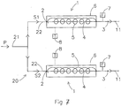
- Fig. 6 shows a variant of the embodiment of a reaction system according to fig. 3 .
- auxiliary channel 23 is provided, through which a tertiary fluid flow TF can pass.
- the resistance to fluid flow of the auxiliary channel is much less then the resistance to fluid flow in the capillaries of the capillary units 1. As a result of that, most of the primary fluid flow P leaves reaction system via the auxiliary channel 23.
- the primary fluid flow is 10 microliter per minute
- the secondary fluid flow through the first capillary unit is 6 microliter per minute
- the secondary fluid flow through the second capillary unit is 4 microliter per minute.
- the capillary of the second capillary unit is heated, and the flow rate through the second capillary unit changes to 4.5 microliter per minute. If the flow rate of the primary fluid flow is kept constant, the fluid flow through the first capillary unit as a consequence changes to 5.5 microliter per minute.
- the primary fluid flow is 10 microliter per minute
- the tertiary fluid flow through the auxiliary channel 23 is 8 microliter per minute
- the secondary fluid flow through the first capillary unit is 1 microliter per minute
- the secondary fluid flow through the second capillary unit is also 1 microliter per minute.
- the capillary of the second capillary unit is heated, and the flow rate through the second capillary unit changes to 1.5 microliter per minute. If the flow rate of the primary fluid flow is kept constant, the fluid flow through the auxiliary channel as a consequence changes to 7.56 microliter per minute and the fluid flow through the first capillary unit as a consequence changes to 0.94 microliter per minute.
- the flow rate values and ratios as mentioned above are merely an example to illustrate the effect of the auxiliary channel.
- the flow rate through the auxiliary channel can be for example 10 to 50 to 100 times, or even more, than the flow rate through each of the capillaries.
- each capillary unit only receives 0,625% of the fluid of the primary fluid flow.
- the auxiliary channel can take the fluid back to the source from which it came before entering the manifold inlet, to waste or to a separate discharge.
- An auxiliary channel of the type as shown in fig. 6 can be used in combination with any of the reaction systems according to the invention.
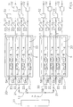
- Fig. 7 shows an embodiment of a flow splitter according to the invention.
- the same principle is used as in the capillary unit according to fig. 1 .
- a primary flow P of fluid is supplied to a manifold inlet 21 of a manifold 20.
- primary fluid flow P is divided over two secondary fluid flows S1,S2.
- each secondary fluid flow S1,S2 will be directed to a device in which it is used, such as a reaction vessel.
- the secondary fluid flows S1,S2 can be supplied to two parallel reaction vessels for performing parallel chemical tests. It is possible of course that the manifold has more than two manifold outlets, so that more than two secondary flows are created. This does however not alter the technical principle of the flow splitter.
- the secondary fluid flows have flow rates that are in a predetermined proportion to each other.
- the flow rates of all fluid flows are desired to be equal, or the flow rate of S1 has to be twice the flow rate of S2. This can be achieved with the flow splitter according to the invention.
- the flow splitter of fig. 7 comprises two capillary units 1, which are similar to the capillary unit according to fig. 1 .
- Each capillary unit 1 of the flow splitter receives a secondary fluid flow from an associated manifold outlet 22 at capillary unit inlet 2.
- the secondary fluid flows are adjusted in the same way as the fluid flow through the capillary in to fig. 1 . So, the flow rate of each secondary fluid flow is measured by a flow sensor 7, and based on the measured flow rate, the temperature control unit 8 makes that the heater and/or cooler 5 in the housing 6 of capillary unit 1 to which the measured flow rate pertains heat or cool the capillary 4 in that housing 6. By changing the capillary temperature, the flow rate of the fluid flow through the capillary is adjusted.
- the thermally insulated housing 6 of the capillary 4 of each capillary unit 1 prevents that the temperature of one capillary 4 influences the temperature of an other capillary 4 that is arranged nearby. Also, other thermal influences from the environment are reduced, as well as heat loss to the environment from the heater/cooler 5. This allows accurate control of the temperature of each individual capillary 4, and therewith accurate control of the flow rate of each individual second fluid flow.
- the flow splitter further comprises a flow distribution controller, which communicates with the individual flow adjustment units (preferably directly with the temperature control devices of the individual flow adjustment devices) of the flow splitter.
- the flow distribution controller receives the measured flow rates from all flow sensors 7 of the flow splitter. It compares the flow rates of the individual secondary fluid flows with each other, and determines whether the flow rates are in the desired proportions to each other. If this is not the case, then the flow distribution controller activates one or more of the individual flow adjusting units, preferably directly the temperature control devices, to adjust the flow rate of the associated secondary fluid flow.
- the flow rates of the other secondary fluid flows will change somewhat too.
- obtaining the desired relative proportions of the flow rates of the secondary fluid flows that is: the desired distribution of the primary fluid flow over the secondary fluid flows, will require some iterations.
- the flow rate of the primary fluid flow is allowed to vary. In that case, it will usually be easier to obtain the desired relative proportions of the flow rates of the secondary fluid flows.
- the pressure in the fluid supply unit may be kept constant while the flow rate of the primary fluid flow is allowed to vary.
- the components of the flow splitter are arranged in a cassette, so that the flow splitter can be attached to other components of the system in which it is used in an easy way.
- the capillary units are releasably arranged in the cassette so that they can easily be exchanged for other capillary units, for example capillary units with a different range of resistance to fluid flow.
Landscapes
- Chemical & Material Sciences (AREA)
- Physics & Mathematics (AREA)
- General Physics & Mathematics (AREA)
- Engineering & Computer Science (AREA)
- Automation & Control Theory (AREA)
- Organic Chemistry (AREA)
- Chemical Kinetics & Catalysis (AREA)
- Physical Or Chemical Processes And Apparatus (AREA)
- Automatic Analysis And Handling Materials Therefor (AREA)
Claims (9)
- Séparateur d'écoulement pour séparer un écoulement de fluide primaire en une pluralité d'écoulements de fluide secondaires pour conduire des expériences,
lequel séparateur d'écoulement comprend :- un collecteur, lequel collecteur a une entrée de collecteur pour recevoir l'écoulement de fluide primaire et une pluralité de sorties de collecteur pour libérer la pluralité d'écoulements de fluide secondaires,- une pluralité d'unités capillaires, chacune des unités capillaires comprenant :- une entrée d'unité pour recevoir un écoulement de fluide secondaire provenant d'une sortie de collecteur,- une sortie d'unité pour libérer ledit écoulement de fluide secondaire,- un capillaire, lequel capillaire est agencé entre l'entrée d'unité et la sortie d'unité de telle sorte que ledit écoulement de fluide secondaire traverse le capillaire,- un appareil de chauffage et/ou un appareil de refroidissement pour régler la température du capillaire et avec lequel influencer le débit de l'écoulement de fluide secondaire traversant ledit capillaire,- un boîtier pour recevoir au moins le capillaire et l'appareil de chauffage et/ou l'appareil de refroidissement de ladite unité capillaire, lequel boîtier assure une isolation thermique du capillaire,- un capteur de débit pour mesurer le débit de l'écoulement de fluide secondaire à travers l'unité capillaire, lequel capteur de débit peut être agencé soit à l'intérieur soit à l'extérieur du boîtier,- une unité de réglage d'écoulement pour régler les débits des écoulements de fluide secondaires, laquelle unité de réglage d'écoulement comprend un dispositif de commande de température pour commander individuellement l'appareil de chauffage et/ou l'appareil de refroidissement de chaque unité capillaire en réponse au débit qui est mesuré par le capteur de débit de cette unité capillaire,le capillaire dans le boîtier de chaque unité capillaire ayant été préparé au préalable et la résistance à l'écoulement de fluide du capillaire à une température de référence et avec un fluide d'une viscosité connue ayant été mesurée et étant connue ; et
les unités capillaires étant échangeables. - Séparateur d'écoulement selon la revendication 1,
le séparateur d'écoulement comprenant une cassette pour recevoir les composants du séparateur d'écoulement, dans laquelle cassette les unités capillaires sont agencées de façon libérable de telle sorte qu'elles peuvent être échangées. - Système de réaction pour conduire des expériences en parallèle,
lequel système de réaction comprend :- une unité de distribution de fluide pour distribuer un écoulement de fluide primaire,- un séparateur d'écoulement selon la revendication 1, dans lequel l'entrée de collecteur est reliée à l'unité de distribution de fluide pour recevoir l'écoulement de fluide primaire provenant de l'unité de distribution de fluide,- une pluralité de cuves de réaction, chaque cuve de réaction comprenant au moins une entrée de cuve de réaction, une entrée de cuve de réaction pour chaque cuve de réaction étant reliée à une sortie d'unité capillaire associée pour recevoir un écoulement de fluide secondaire provenant du séparateur d'écoulement. - Système de réaction selon la revendication 3, le système de réaction comprenant un bloc de réaction pour recevoir les cuves de réaction et/ou une ou plusieurs cassettes, chaque cassette recevant au moins l'une de la pluralité d'unités capillaires du séparateur d'écoulement, et une enceinte ou un châssis pour recevoir au moins le bloc de réaction et la ou les cassettes.
- Système de réaction selon la revendication 3, le système de réaction comprenant un dispositif de commande de distribution d'écoulement pour garantir que les débits du premier écoulement de fluide primaire et du second écoulement de fluide primaire sont dans une proportion souhaitée l'un par rapport à l'autre.
- Système de réaction selon la revendication 3, dans lequel l'appareil de chauffage et/ou l'appareil de refroidissement est un appareil de chauffage comprenant un fil de résistance électrique, lequel fil produit de la chaleur lorsqu'un courant électrique y circule, et lequel fil est enroulé autour du capillaire.
- Système de réaction selon la revendication 3, dans lequel le capillaire est enroulé autour d'un noyau, lequel noyau comporte des moyens de chauffage et/ou de refroidissement.
- Système de réaction selon la revendication 3, le système de réaction comprenant un canal auxiliaire qui est relié au collecteur, lequel canal auxiliaire a une résistance à l'écoulement de fluide qui est inférieure à la résistance à l'écoulement de fluide des capillaires des unités capillaires.
- Système de réaction pour conduire des expériences,
lequel système de réaction comprend :- une cuve de réaction, ladite cuve de réaction comprenant au moins une entrée de cuve de réaction, laquelle entrée de cuve de réaction est apte à être reliée à une unité de distribution de fluide pour recevoir un écoulement de fluide,
chaque cuve de réaction comprenant en outre au moins une sortie de cuve de réaction pour libérer un écoulement d'effluent,- une ligne d'effluent de cuve de réaction pour recevoir l'écoulement d'effluent provenant de la cuve de réaction, laquelle ligne d'effluent est en communication fluidique avec au moins une sortie de cuve de réaction, laquelle ligne d'effluent de cuve de réaction comporte une ouverture pour libérer un écoulement de commande de pression,- un système de commande de contre-pression comprenant une unité capillaire, laquelle unité capillaire comprendle système de commande de contre-pression comprenant en outre une unité de réglage d'écoulement pour régler les débits de l'écoulement de commande de pression,- une entrée d'unité pour recevoir l'écoulement de commande de pression provenant de l'ouverture dans la ligne d'effluent de cuve de réaction,- une sortie d'unité pour libérer ledit écoulement de commande de pression provenant de l'unité capillaire,- un capillaire, lequel capillaire est agencé entre l'entrée d'unité et la sortie d'unité de telle sorte que l'écoulement de commande de pression traverse le capillaire,- un appareil de chauffage et/ou un appareil de refroidissement pour régler la température du capillaire et avec lequel influencer le débit de l'écoulement de commande de pression traversant ledit capillaire,- un boîtier pour recevoir au moins le capillaire et l'appareil de chauffage et/ou l'appareil de refroidissement de ladite unité capillaire, lequel boîtier assure une isolation thermique du capillaire,- un capteur de débit qui est adapté pour mesurer le débit de l'écoulement de commande de pression à travers l'unité capillaire,
laquelle unité de réglage d'écoulement comprend un dispositif de commande de température pour commander l'appareil de chauffage et/ou l'appareil de refroidissement de l'unité capillaire
le capillaire dans le boîtier de chaque unité capillaire ayant été préparé au préalable et la résistance à l'écoulement de fluide du capillaire à une température de référence et avec un fluide d'une viscosité connue ayant été mesurée et étant connue ; et
l'unité capillaire étant échangeable.
Applications Claiming Priority (4)
| Application Number | Priority Date | Filing Date | Title |
|---|---|---|---|
| NL2001617 | 2008-05-26 | ||
| NL2001711 | 2008-06-23 | ||
| NL2002365A NL2002365C2 (en) | 2008-05-26 | 2008-12-23 | Flow splitter and reaction assembly. |
| PCT/NL2009/000122 WO2009145614A2 (fr) | 2008-05-26 | 2009-05-26 | Ensemble de réaction et séparateur d’écoulement |
Publications (2)
| Publication Number | Publication Date |
|---|---|
| EP2294491A2 EP2294491A2 (fr) | 2011-03-16 |
| EP2294491B1 true EP2294491B1 (fr) | 2020-02-12 |
Family
ID=41377820
Family Applications (1)
| Application Number | Title | Priority Date | Filing Date |
|---|---|---|---|
| EP09755071.9A Active EP2294491B1 (fr) | 2008-05-26 | 2009-05-26 | Ensemble de réaction et séparateur d écoulement |
Country Status (8)
| Country | Link |
|---|---|
| US (1) | US20110108132A1 (fr) |
| EP (1) | EP2294491B1 (fr) |
| CN (1) | CN102084310A (fr) |
| BR (1) | BRPI0913177A2 (fr) |
| DK (1) | DK2294491T3 (fr) |
| ES (1) | ES2785047T3 (fr) |
| NL (1) | NL2002365C2 (fr) |
| WO (1) | WO2009145614A2 (fr) |
Families Citing this family (10)
| Publication number | Priority date | Publication date | Assignee | Title |
|---|---|---|---|---|
| EP2349569A1 (fr) * | 2008-07-08 | 2011-08-03 | HTE Aktiengesellschaft The High Throughput Experimentation Company | Banc d essai avec limiteurs commandables ou réglables |
| US8250933B2 (en) * | 2010-03-30 | 2012-08-28 | Alstom Technology Ltd | Method and system for measurement of a flow rate of a fluid |
| DE102011102361A1 (de) * | 2011-05-24 | 2012-11-29 | Hte Ag The High Throughput Experimentation Company | Vorrichtung zur Zufuhr von Eduktflüssigkeiten |
| US9684653B1 (en) | 2012-03-06 | 2017-06-20 | Amazon Technologies, Inc. | Foreign language translation using product information |
| NL2009660C2 (en) * | 2012-10-18 | 2014-04-22 | Avantium Technologies B V | Pressure controller. |
| NL2009659C2 (en) * | 2012-10-18 | 2014-04-22 | Avantium Technologies B V | System and method for operating parallel reactors. |
| NL2011856C2 (en) * | 2013-11-28 | 2014-09-25 | Avantium Technologies B V | Reactor system for high throughput applications. |
| EP3331643A1 (fr) * | 2015-08-06 | 2018-06-13 | hte GmbH the high throughput experimentation company | Élément d'écoulement muni d'une conduite capillaire intégrée pour le transfert de fluides |
| US11752484B2 (en) | 2018-09-24 | 2023-09-12 | Hte Gmbh The High Throughput Experimentation | Apparatus and method for analyzing reactions |
| CN114442687A (zh) * | 2020-10-30 | 2022-05-06 | 潘晨 | 一种并行流体压力控制器 |
Citations (1)
| Publication number | Priority date | Publication date | Assignee | Title |
|---|---|---|---|---|
| EP1707941A2 (fr) * | 2005-03-28 | 2006-10-04 | Wyatt Technology Corporation | Moyens et procédé d'équilibrage de pont automatiques pour un viscosimètre de pont capillaire |
Family Cites Families (15)
| Publication number | Priority date | Publication date | Assignee | Title |
|---|---|---|---|---|
| IT1274775B (it) * | 1994-09-16 | 1997-07-24 | Fisons Instr Spa | Metodo e dispositivo per il controllo della portata di gas vettore in apparecchi gascromatografici |
| US5681534A (en) * | 1995-07-20 | 1997-10-28 | Neves; Richard S. | High throughput oligonucleotide synthesizer |
| US6149882A (en) * | 1998-06-09 | 2000-11-21 | Symyx Technologies, Inc. | Parallel fixed bed reactor and fluid contacting apparatus |
| US6749814B1 (en) * | 1999-03-03 | 2004-06-15 | Symyx Technologies, Inc. | Chemical processing microsystems comprising parallel flow microreactors and methods for using same |
| US20020042140A1 (en) * | 1999-03-03 | 2002-04-11 | Alfred Hagemeyer | Methods for analysis of heterogeneous catalysts in a multi-variable screening reactor |
| US6119710A (en) * | 1999-05-26 | 2000-09-19 | Cyber Instrument Technologies Llc | Method for wide range gas flow system with real time flow measurement and correction |
| GB2373054B (en) * | 1999-05-26 | 2003-03-26 | Cyber Instr Technology Llc | Wide range gas flow system with real time flow measurement and correction |
| DE60108482T2 (de) * | 2000-03-07 | 2006-02-16 | Symyx Technologies, Inc., Santa Clara | Prozessoptimierungsreaktor mit parallelem durchfluss |
| FR2817347B1 (fr) * | 2000-11-29 | 2003-01-03 | Commissariat Energie Atomique | Dispositif de couplage d'un microchromatographe avec un spectrometre de masse et dispositif d'analyse |
| US6960235B2 (en) * | 2001-12-05 | 2005-11-01 | The Regents Of The University Of California | Chemical microreactor and method thereof |
| US6901334B2 (en) * | 2001-12-17 | 2005-05-31 | Rohm And Haas Company | Methods and systems for high throughput analysis |
| WO2004010087A2 (fr) * | 2002-07-19 | 2004-01-29 | Celerity Group, Inc | Debitmetre |
| US7758814B2 (en) * | 2004-06-05 | 2010-07-20 | Freeslate, Inc. | Microfluidic fluid distribution manifold for use with multi-channel reactor systems |
| US7641860B2 (en) * | 2006-06-01 | 2010-01-05 | Nanotek, Llc | Modular and reconfigurable multi-stage microreactor cartridge apparatus |
| US7854902B2 (en) * | 2006-08-23 | 2010-12-21 | Nanotek, Llc | Modular and reconfigurable multi-stage high temperature microreactor cartridge apparatus and system for using same |
-
2008
- 2008-12-23 NL NL2002365A patent/NL2002365C2/en not_active IP Right Cessation
-
2009
- 2009-05-26 WO PCT/NL2009/000122 patent/WO2009145614A2/fr not_active Ceased
- 2009-05-26 DK DK09755071.9T patent/DK2294491T3/da active
- 2009-05-26 BR BRPI0913177A patent/BRPI0913177A2/pt not_active Application Discontinuation
- 2009-05-26 US US12/992,436 patent/US20110108132A1/en not_active Abandoned
- 2009-05-26 ES ES09755071T patent/ES2785047T3/es active Active
- 2009-05-26 CN CN200980118432XA patent/CN102084310A/zh active Pending
- 2009-05-26 EP EP09755071.9A patent/EP2294491B1/fr active Active
Patent Citations (1)
| Publication number | Priority date | Publication date | Assignee | Title |
|---|---|---|---|---|
| EP1707941A2 (fr) * | 2005-03-28 | 2006-10-04 | Wyatt Technology Corporation | Moyens et procédé d'équilibrage de pont automatiques pour un viscosimètre de pont capillaire |
Also Published As
| Publication number | Publication date |
|---|---|
| NL2002365C2 (en) | 2011-04-05 |
| BRPI0913177A2 (pt) | 2016-01-12 |
| EP2294491A2 (fr) | 2011-03-16 |
| ES2785047T3 (es) | 2020-10-05 |
| US20110108132A1 (en) | 2011-05-12 |
| WO2009145614A3 (fr) | 2011-01-06 |
| NL2002365A1 (nl) | 2009-11-27 |
| WO2009145614A2 (fr) | 2009-12-03 |
| DK2294491T3 (da) | 2020-05-18 |
| CN102084310A (zh) | 2011-06-01 |
Similar Documents
| Publication | Publication Date | Title |
|---|---|---|
| EP2294491B1 (fr) | Ensemble de réaction et séparateur d écoulement | |
| CN104822450B (zh) | 压力控制器 | |
| CN104812476B (zh) | 用于运行并行反应器的系统及方法 | |
| US20120003122A1 (en) | Flow controller assembly for microfluidic applications and system for performing a plurality of experiments in parallel | |
| JP6619792B2 (ja) | 改善されたガス流量制御 | |
| EP0370162A2 (fr) | Méthode et appareil de mesure et de commande de débit de fluide | |
| US10639627B2 (en) | Fluid analyzer manifold and techniques | |
| EP3339815B1 (fr) | Unité de capteur mesurant le débit massique d'une colle thermofusible liquide | |
| US4989637A (en) | Gas mixing apparatus | |
| JP2021530076A5 (fr) | ||
| KR20190074930A (ko) | 질량유량제어기 | |
| US5394704A (en) | Alternate method for achieving temperature control in the -160 to +90 degrees Celcius range | |
| Biessey et al. | Influence of design parameters on hydrodynamics and heat transfer of a modularized millireactor | |
| KR20170000367A (ko) | 가스 또는 액체를 위한 온도 제어 유닛 | |
| JP2000230670A (ja) | ヒータ付き集積流体制御装置 | |
| CN215987043U (zh) | 一种并行流体压力控制器 | |
| US5626166A (en) | Temperature control valve without moving parts | |
| RU2201580C2 (ru) | Устройство для измерения микрорасхода газа | |
| CN114442687A (zh) | 一种并行流体压力控制器 | |
| RU2262666C1 (ru) | Тепловой микрорасходомер газа | |
| US20230220923A1 (en) | Fluid delivery mounting panel and system | |
| RU2326350C2 (ru) | Тепловой микрорасходомер газа | |
| RU2106604C1 (ru) | Тепловой расходомер | |
| Rumyantsev et al. | A heat thermistor gas microflowmeter |
Legal Events
| Date | Code | Title | Description |
|---|---|---|---|
| PUAI | Public reference made under article 153(3) epc to a published international application that has entered the european phase |
Free format text: ORIGINAL CODE: 0009012 |
|
| 17P | Request for examination filed |
Effective date: 20101222 |
|
| AK | Designated contracting states |
Kind code of ref document: A2 Designated state(s): AT BE BG CH CY CZ DE DK EE ES FI FR GB GR HR HU IE IS IT LI LT LU LV MC MK MT NL NO PL PT RO SE SI SK TR |
|
| AX | Request for extension of the european patent |
Extension state: AL BA RS |
|
| DAX | Request for extension of the european patent (deleted) | ||
| STAA | Information on the status of an ep patent application or granted ep patent |
Free format text: STATUS: EXAMINATION IS IN PROGRESS |
|
| 17Q | First examination report despatched |
Effective date: 20171109 |
|
| RAP1 | Party data changed (applicant data changed or rights of an application transferred) |
Owner name: AVANTIUM TECHNOLOGIES B.V. |
|
| RIC1 | Information provided on ipc code assigned before grant |
Ipc: G05D 11/13 20060101ALI20190806BHEP Ipc: G05D 7/06 20060101AFI20190806BHEP Ipc: B01J 19/00 20060101ALI20190806BHEP |
|
| GRAP | Despatch of communication of intention to grant a patent |
Free format text: ORIGINAL CODE: EPIDOSNIGR1 |
|
| STAA | Information on the status of an ep patent application or granted ep patent |
Free format text: STATUS: GRANT OF PATENT IS INTENDED |
|
| INTG | Intention to grant announced |
Effective date: 20190919 |
|
| GRAS | Grant fee paid |
Free format text: ORIGINAL CODE: EPIDOSNIGR3 |
|
| GRAA | (expected) grant |
Free format text: ORIGINAL CODE: 0009210 |
|
| STAA | Information on the status of an ep patent application or granted ep patent |
Free format text: STATUS: THE PATENT HAS BEEN GRANTED |
|
| AK | Designated contracting states |
Kind code of ref document: B1 Designated state(s): AT BE BG CH CY CZ DE DK EE ES FI FR GB GR HR HU IE IS IT LI LT LU LV MC MK MT NL NO PL PT RO SE SI SK TR |
|
| REG | Reference to a national code |
Ref country code: GB Ref legal event code: FG4D |
|
| REG | Reference to a national code |
Ref country code: CH Ref legal event code: EP |
|
| REG | Reference to a national code |
Ref country code: AT Ref legal event code: REF Ref document number: 1232971 Country of ref document: AT Kind code of ref document: T Effective date: 20200215 |
|
| REG | Reference to a national code |
Ref country code: IE Ref legal event code: FG4D |
|
| REG | Reference to a national code |
Ref country code: DE Ref legal event code: R096 Ref document number: 602009061158 Country of ref document: DE |
|
| REG | Reference to a national code |
Ref country code: NL Ref legal event code: FP |
|
| REG | Reference to a national code |
Ref country code: DK Ref legal event code: T3 Effective date: 20200511 |
|
| PG25 | Lapsed in a contracting state [announced via postgrant information from national office to epo] |
Ref country code: NO Free format text: LAPSE BECAUSE OF FAILURE TO SUBMIT A TRANSLATION OF THE DESCRIPTION OR TO PAY THE FEE WITHIN THE PRESCRIBED TIME-LIMIT Effective date: 20200512 Ref country code: FI Free format text: LAPSE BECAUSE OF FAILURE TO SUBMIT A TRANSLATION OF THE DESCRIPTION OR TO PAY THE FEE WITHIN THE PRESCRIBED TIME-LIMIT Effective date: 20200212 |
|
| REG | Reference to a national code |
Ref country code: LT Ref legal event code: MG4D |
|
| PG25 | Lapsed in a contracting state [announced via postgrant information from national office to epo] |
Ref country code: BG Free format text: LAPSE BECAUSE OF FAILURE TO SUBMIT A TRANSLATION OF THE DESCRIPTION OR TO PAY THE FEE WITHIN THE PRESCRIBED TIME-LIMIT Effective date: 20200512 Ref country code: GR Free format text: LAPSE BECAUSE OF FAILURE TO SUBMIT A TRANSLATION OF THE DESCRIPTION OR TO PAY THE FEE WITHIN THE PRESCRIBED TIME-LIMIT Effective date: 20200513 Ref country code: IS Free format text: LAPSE BECAUSE OF FAILURE TO SUBMIT A TRANSLATION OF THE DESCRIPTION OR TO PAY THE FEE WITHIN THE PRESCRIBED TIME-LIMIT Effective date: 20200612 Ref country code: HR Free format text: LAPSE BECAUSE OF FAILURE TO SUBMIT A TRANSLATION OF THE DESCRIPTION OR TO PAY THE FEE WITHIN THE PRESCRIBED TIME-LIMIT Effective date: 20200212 Ref country code: LV Free format text: LAPSE BECAUSE OF FAILURE TO SUBMIT A TRANSLATION OF THE DESCRIPTION OR TO PAY THE FEE WITHIN THE PRESCRIBED TIME-LIMIT Effective date: 20200212 Ref country code: SE Free format text: LAPSE BECAUSE OF FAILURE TO SUBMIT A TRANSLATION OF THE DESCRIPTION OR TO PAY THE FEE WITHIN THE PRESCRIBED TIME-LIMIT Effective date: 20200212 |
|
| REG | Reference to a national code |
Ref country code: ES Ref legal event code: FG2A Ref document number: 2785047 Country of ref document: ES Kind code of ref document: T3 Effective date: 20201005 |
|
| PG25 | Lapsed in a contracting state [announced via postgrant information from national office to epo] |
Ref country code: PT Free format text: LAPSE BECAUSE OF FAILURE TO SUBMIT A TRANSLATION OF THE DESCRIPTION OR TO PAY THE FEE WITHIN THE PRESCRIBED TIME-LIMIT Effective date: 20200705 Ref country code: CZ Free format text: LAPSE BECAUSE OF FAILURE TO SUBMIT A TRANSLATION OF THE DESCRIPTION OR TO PAY THE FEE WITHIN THE PRESCRIBED TIME-LIMIT Effective date: 20200212 Ref country code: LT Free format text: LAPSE BECAUSE OF FAILURE TO SUBMIT A TRANSLATION OF THE DESCRIPTION OR TO PAY THE FEE WITHIN THE PRESCRIBED TIME-LIMIT Effective date: 20200212 Ref country code: RO Free format text: LAPSE BECAUSE OF FAILURE TO SUBMIT A TRANSLATION OF THE DESCRIPTION OR TO PAY THE FEE WITHIN THE PRESCRIBED TIME-LIMIT Effective date: 20200212 Ref country code: EE Free format text: LAPSE BECAUSE OF FAILURE TO SUBMIT A TRANSLATION OF THE DESCRIPTION OR TO PAY THE FEE WITHIN THE PRESCRIBED TIME-LIMIT Effective date: 20200212 Ref country code: SK Free format text: LAPSE BECAUSE OF FAILURE TO SUBMIT A TRANSLATION OF THE DESCRIPTION OR TO PAY THE FEE WITHIN THE PRESCRIBED TIME-LIMIT Effective date: 20200212 |
|
| REG | Reference to a national code |
Ref country code: DE Ref legal event code: R097 Ref document number: 602009061158 Country of ref document: DE |
|
| REG | Reference to a national code |
Ref country code: AT Ref legal event code: MK05 Ref document number: 1232971 Country of ref document: AT Kind code of ref document: T Effective date: 20200212 |
|
| PLBE | No opposition filed within time limit |
Free format text: ORIGINAL CODE: 0009261 |
|
| STAA | Information on the status of an ep patent application or granted ep patent |
Free format text: STATUS: NO OPPOSITION FILED WITHIN TIME LIMIT |
|
| 26N | No opposition filed |
Effective date: 20201113 |
|
| PG25 | Lapsed in a contracting state [announced via postgrant information from national office to epo] |
Ref country code: IT Free format text: LAPSE BECAUSE OF FAILURE TO SUBMIT A TRANSLATION OF THE DESCRIPTION OR TO PAY THE FEE WITHIN THE PRESCRIBED TIME-LIMIT Effective date: 20200212 Ref country code: MC Free format text: LAPSE BECAUSE OF FAILURE TO SUBMIT A TRANSLATION OF THE DESCRIPTION OR TO PAY THE FEE WITHIN THE PRESCRIBED TIME-LIMIT Effective date: 20200212 Ref country code: AT Free format text: LAPSE BECAUSE OF FAILURE TO SUBMIT A TRANSLATION OF THE DESCRIPTION OR TO PAY THE FEE WITHIN THE PRESCRIBED TIME-LIMIT Effective date: 20200212 |
|
| PG25 | Lapsed in a contracting state [announced via postgrant information from national office to epo] |
Ref country code: SI Free format text: LAPSE BECAUSE OF FAILURE TO SUBMIT A TRANSLATION OF THE DESCRIPTION OR TO PAY THE FEE WITHIN THE PRESCRIBED TIME-LIMIT Effective date: 20200212 Ref country code: PL Free format text: LAPSE BECAUSE OF FAILURE TO SUBMIT A TRANSLATION OF THE DESCRIPTION OR TO PAY THE FEE WITHIN THE PRESCRIBED TIME-LIMIT Effective date: 20200212 |
|
| REG | Reference to a national code |
Ref country code: BE Ref legal event code: MM Effective date: 20200531 |
|
| PG25 | Lapsed in a contracting state [announced via postgrant information from national office to epo] |
Ref country code: LU Free format text: LAPSE BECAUSE OF NON-PAYMENT OF DUE FEES Effective date: 20200526 |
|
| PG25 | Lapsed in a contracting state [announced via postgrant information from national office to epo] |
Ref country code: IE Free format text: LAPSE BECAUSE OF NON-PAYMENT OF DUE FEES Effective date: 20200526 |
|
| PG25 | Lapsed in a contracting state [announced via postgrant information from national office to epo] |
Ref country code: BE Free format text: LAPSE BECAUSE OF NON-PAYMENT OF DUE FEES Effective date: 20200531 |
|
| PG25 | Lapsed in a contracting state [announced via postgrant information from national office to epo] |
Ref country code: TR Free format text: LAPSE BECAUSE OF FAILURE TO SUBMIT A TRANSLATION OF THE DESCRIPTION OR TO PAY THE FEE WITHIN THE PRESCRIBED TIME-LIMIT Effective date: 20200212 Ref country code: MT Free format text: LAPSE BECAUSE OF FAILURE TO SUBMIT A TRANSLATION OF THE DESCRIPTION OR TO PAY THE FEE WITHIN THE PRESCRIBED TIME-LIMIT Effective date: 20200212 Ref country code: CY Free format text: LAPSE BECAUSE OF FAILURE TO SUBMIT A TRANSLATION OF THE DESCRIPTION OR TO PAY THE FEE WITHIN THE PRESCRIBED TIME-LIMIT Effective date: 20200212 |
|
| PG25 | Lapsed in a contracting state [announced via postgrant information from national office to epo] |
Ref country code: MK Free format text: LAPSE BECAUSE OF FAILURE TO SUBMIT A TRANSLATION OF THE DESCRIPTION OR TO PAY THE FEE WITHIN THE PRESCRIBED TIME-LIMIT Effective date: 20200212 |
|
| P01 | Opt-out of the competence of the unified patent court (upc) registered |
Effective date: 20230331 |
|
| PGFP | Annual fee paid to national office [announced via postgrant information from national office to epo] |
Ref country code: NL Payment date: 20250526 Year of fee payment: 17 |
|
| PGFP | Annual fee paid to national office [announced via postgrant information from national office to epo] |
Ref country code: DE Payment date: 20250529 Year of fee payment: 17 |
|
| PGFP | Annual fee paid to national office [announced via postgrant information from national office to epo] |
Ref country code: ES Payment date: 20250602 Year of fee payment: 17 Ref country code: DK Payment date: 20250526 Year of fee payment: 17 Ref country code: GB Payment date: 20250527 Year of fee payment: 17 |
|
| PGFP | Annual fee paid to national office [announced via postgrant information from national office to epo] |
Ref country code: FR Payment date: 20250526 Year of fee payment: 17 |
|
| PGFP | Annual fee paid to national office [announced via postgrant information from national office to epo] |
Ref country code: CH Payment date: 20250601 Year of fee payment: 17 |