EP2294931A1 - Verbessertes Verfahren und verbesserte Vorrichtung für ertragreiche Pflanzenbestandteile - Google Patents
Verbessertes Verfahren und verbesserte Vorrichtung für ertragreiche Pflanzenbestandteile Download PDFInfo
- Publication number
- EP2294931A1 EP2294931A1 EP09169271A EP09169271A EP2294931A1 EP 2294931 A1 EP2294931 A1 EP 2294931A1 EP 09169271 A EP09169271 A EP 09169271A EP 09169271 A EP09169271 A EP 09169271A EP 2294931 A1 EP2294931 A1 EP 2294931A1
- Authority
- EP
- European Patent Office
- Prior art keywords
- plant
- steam
- distillation
- plants
- water
- Prior art date
- Legal status (The legal status is an assumption and is not a legal conclusion. Google has not performed a legal analysis and makes no representation as to the accuracy of the status listed.)
- Withdrawn
Links
- 239000004615 ingredient Substances 0.000 title claims abstract description 173
- 238000000034 method Methods 0.000 title claims abstract description 89
- 230000008569 process Effects 0.000 title claims abstract description 82
- 238000004821 distillation Methods 0.000 claims abstract description 198
- XLYOFNOQVPJJNP-UHFFFAOYSA-N water Substances O XLYOFNOQVPJJNP-UHFFFAOYSA-N 0.000 claims abstract description 145
- 230000001174 ascending effect Effects 0.000 claims abstract description 24
- 239000000463 material Substances 0.000 claims description 81
- 238000000605 extraction Methods 0.000 claims description 58
- 229910052500 inorganic mineral Inorganic materials 0.000 claims description 29
- 239000011707 mineral Substances 0.000 claims description 29
- 239000000654 additive Substances 0.000 claims description 26
- 230000001681 protective effect Effects 0.000 claims description 26
- 239000012530 fluid Substances 0.000 claims description 19
- 239000007788 liquid Substances 0.000 claims description 17
- 239000000725 suspension Substances 0.000 claims description 17
- 238000009833 condensation Methods 0.000 claims description 16
- 230000005494 condensation Effects 0.000 claims description 16
- 238000001704 evaporation Methods 0.000 claims description 11
- 230000008020 evaporation Effects 0.000 claims description 10
- 230000000996 additive effect Effects 0.000 claims description 9
- 229910052902 vermiculite Inorganic materials 0.000 claims description 9
- 239000010455 vermiculite Substances 0.000 claims description 9
- 235000019354 vermiculite Nutrition 0.000 claims description 9
- 238000009792 diffusion process Methods 0.000 claims description 7
- 239000003077 lignite Substances 0.000 claims description 7
- HEBKCHPVOIAQTA-UHFFFAOYSA-N meso ribitol Natural products OCC(O)C(O)C(O)CO HEBKCHPVOIAQTA-UHFFFAOYSA-N 0.000 claims description 7
- 235000010447 xylitol Nutrition 0.000 claims description 7
- HEBKCHPVOIAQTA-SCDXWVJYSA-N xylitol Chemical compound OC[C@H](O)[C@@H](O)[C@H](O)CO HEBKCHPVOIAQTA-SCDXWVJYSA-N 0.000 claims description 7
- 230000000630 rising effect Effects 0.000 claims description 6
- 235000013399 edible fruits Nutrition 0.000 claims description 5
- 235000019362 perlite Nutrition 0.000 claims description 5
- 238000009835 boiling Methods 0.000 claims description 4
- 239000007900 aqueous suspension Substances 0.000 claims description 3
- GUJOJGAPFQRJSV-UHFFFAOYSA-N dialuminum;dioxosilane;oxygen(2-);hydrate Chemical compound O.[O-2].[O-2].[O-2].[Al+3].[Al+3].O=[Si]=O.O=[Si]=O.O=[Si]=O.O=[Si]=O GUJOJGAPFQRJSV-UHFFFAOYSA-N 0.000 claims description 3
- 229910052901 montmorillonite Inorganic materials 0.000 claims description 3
- 150000004760 silicates Chemical class 0.000 claims description 3
- 238000009827 uniform distribution Methods 0.000 claims description 3
- 241000196324 Embryophyta Species 0.000 description 474
- 239000007789 gas Substances 0.000 description 40
- 239000000203 mixture Substances 0.000 description 29
- 239000003921 oil Substances 0.000 description 26
- 235000019198 oils Nutrition 0.000 description 26
- 239000000341 volatile oil Substances 0.000 description 26
- 239000000126 substance Substances 0.000 description 22
- 239000000047 product Substances 0.000 description 21
- 239000000243 solution Substances 0.000 description 14
- 210000004027 cell Anatomy 0.000 description 13
- 239000000796 flavoring agent Substances 0.000 description 13
- 238000000926 separation method Methods 0.000 description 13
- IJGRMHOSHXDMSA-UHFFFAOYSA-N Atomic nitrogen Chemical compound N#N IJGRMHOSHXDMSA-UHFFFAOYSA-N 0.000 description 12
- 235000019634 flavors Nutrition 0.000 description 12
- XKRFYHLGVUSROY-UHFFFAOYSA-N Argon Chemical compound [Ar] XKRFYHLGVUSROY-UHFFFAOYSA-N 0.000 description 10
- 238000011049 filling Methods 0.000 description 10
- 238000010438 heat treatment Methods 0.000 description 10
- 238000003306 harvesting Methods 0.000 description 9
- 238000001256 steam distillation Methods 0.000 description 9
- 238000002955 isolation Methods 0.000 description 8
- 230000000694 effects Effects 0.000 description 7
- 238000002474 experimental method Methods 0.000 description 7
- WTEVQBCEXWBHNA-JXMROGBWSA-N geranial Chemical compound CC(C)=CCC\C(C)=C\C=O WTEVQBCEXWBHNA-JXMROGBWSA-N 0.000 description 7
- LFQSCWFLJHTTHZ-UHFFFAOYSA-N Ethanol Chemical compound CCO LFQSCWFLJHTTHZ-UHFFFAOYSA-N 0.000 description 6
- 230000006978 adaptation Effects 0.000 description 6
- 150000002148 esters Chemical class 0.000 description 6
- 238000002156 mixing Methods 0.000 description 6
- 229910052757 nitrogen Inorganic materials 0.000 description 6
- 238000011084 recovery Methods 0.000 description 6
- 239000002904 solvent Substances 0.000 description 6
- 230000007704 transition Effects 0.000 description 6
- -1 transition metal cations Chemical class 0.000 description 6
- WTEVQBCEXWBHNA-UHFFFAOYSA-N Citral Natural products CC(C)=CCCC(C)=CC=O WTEVQBCEXWBHNA-UHFFFAOYSA-N 0.000 description 5
- 150000001298 alcohols Chemical class 0.000 description 5
- 229910052786 argon Inorganic materials 0.000 description 5
- 230000008901 benefit Effects 0.000 description 5
- 230000008859 change Effects 0.000 description 5
- 238000013461 design Methods 0.000 description 5
- 230000006870 function Effects 0.000 description 5
- 238000005259 measurement Methods 0.000 description 5
- 229910052756 noble gas Inorganic materials 0.000 description 5
- 230000002829 reductive effect Effects 0.000 description 5
- 238000010992 reflux Methods 0.000 description 5
- 229930004725 sesquiterpene Natural products 0.000 description 5
- 150000004354 sesquiterpene derivatives Chemical class 0.000 description 5
- 230000032258 transport Effects 0.000 description 5
- ZFMSMUAANRJZFM-UHFFFAOYSA-N Estragole Chemical compound COC1=CC=C(CC=C)C=C1 ZFMSMUAANRJZFM-UHFFFAOYSA-N 0.000 description 4
- KGEKLUUHTZCSIP-HOSYDEDBSA-N [(1s,4s,6r)-1,7,7-trimethyl-6-bicyclo[2.2.1]heptanyl] acetate Chemical compound C1C[C@]2(C)[C@H](OC(=O)C)C[C@H]1C2(C)C KGEKLUUHTZCSIP-HOSYDEDBSA-N 0.000 description 4
- 150000001299 aldehydes Chemical class 0.000 description 4
- QVGXLLKOCUKJST-UHFFFAOYSA-N atomic oxygen Chemical compound [O] QVGXLLKOCUKJST-UHFFFAOYSA-N 0.000 description 4
- NEHNMFOYXAPHSD-UHFFFAOYSA-N citronellal Chemical compound O=CCC(C)CCC=C(C)C NEHNMFOYXAPHSD-UHFFFAOYSA-N 0.000 description 4
- 238000004891 communication Methods 0.000 description 4
- 238000010276 construction Methods 0.000 description 4
- CDOSHBSSFJOMGT-UHFFFAOYSA-N linalool Chemical compound CC(C)=CCCC(C)(O)C=C CDOSHBSSFJOMGT-UHFFFAOYSA-N 0.000 description 4
- 238000004519 manufacturing process Methods 0.000 description 4
- 229930003658 monoterpene Natural products 0.000 description 4
- 150000002773 monoterpene derivatives Chemical class 0.000 description 4
- 235000002577 monoterpenes Nutrition 0.000 description 4
- 239000001301 oxygen Substances 0.000 description 4
- 229910052760 oxygen Inorganic materials 0.000 description 4
- 238000003825 pressing Methods 0.000 description 4
- 238000003756 stirring Methods 0.000 description 4
- 230000008961 swelling Effects 0.000 description 4
- WKWATASPNZWAFM-UHFFFAOYSA-N Carotol Natural products CC1CCC2C(CCC(=C2C1)C)C(C)(C)O WKWATASPNZWAFM-UHFFFAOYSA-N 0.000 description 3
- XZYQCFABZDVOPN-ILXRZTDVSA-N Carotol Chemical compound C1C=C(C)CC[C@]2(O)[C@@H](C(C)C)CC[C@@]21C XZYQCFABZDVOPN-ILXRZTDVSA-N 0.000 description 3
- 244000062730 Melissa officinalis Species 0.000 description 3
- 235000010654 Melissa officinalis Nutrition 0.000 description 3
- 238000007664 blowing Methods 0.000 description 3
- 239000006227 byproduct Substances 0.000 description 3
- 238000006243 chemical reaction Methods 0.000 description 3
- 229940043350 citral Drugs 0.000 description 3
- HIGQPQRQIQDZMP-UHFFFAOYSA-N geranil acetate Natural products CC(C)=CCCC(C)=CCOC(C)=O HIGQPQRQIQDZMP-UHFFFAOYSA-N 0.000 description 3
- HIGQPQRQIQDZMP-DHZHZOJOSA-N geranyl acetate Chemical compound CC(C)=CCC\C(C)=C\COC(C)=O HIGQPQRQIQDZMP-DHZHZOJOSA-N 0.000 description 3
- 239000011521 glass Substances 0.000 description 3
- 230000006872 improvement Effects 0.000 description 3
- 150000002576 ketones Chemical class 0.000 description 3
- 239000011490 mineral wool Substances 0.000 description 3
- 150000002835 noble gases Chemical class 0.000 description 3
- 238000007254 oxidation reaction Methods 0.000 description 3
- 238000012856 packing Methods 0.000 description 3
- 239000010451 perlite Substances 0.000 description 3
- 238000012360 testing method Methods 0.000 description 3
- 238000012546 transfer Methods 0.000 description 3
- XHXUANMFYXWVNG-ADEWGFFLSA-N (-)-Menthyl acetate Chemical compound CC(C)[C@@H]1CC[C@@H](C)C[C@H]1OC(C)=O XHXUANMFYXWVNG-ADEWGFFLSA-N 0.000 description 2
- 239000001490 (3R)-3,7-dimethylocta-1,6-dien-3-ol Substances 0.000 description 2
- JSNRRGGBADWTMC-UHFFFAOYSA-N (6E)-7,11-dimethyl-3-methylene-1,6,10-dodecatriene Chemical compound CC(C)=CCCC(C)=CCCC(=C)C=C JSNRRGGBADWTMC-UHFFFAOYSA-N 0.000 description 2
- CDOSHBSSFJOMGT-JTQLQIEISA-N (R)-linalool Natural products CC(C)=CCC[C@@](C)(O)C=C CDOSHBSSFJOMGT-JTQLQIEISA-N 0.000 description 2
- FAMPSKZZVDUYOS-UHFFFAOYSA-N 2,6,6,9-tetramethylcycloundeca-1,4,8-triene Chemical compound CC1=CCC(C)(C)C=CCC(C)=CCC1 FAMPSKZZVDUYOS-UHFFFAOYSA-N 0.000 description 2
- WRYLYDPHFGVWKC-UHFFFAOYSA-N 4-terpineol Chemical compound CC(C)C1(O)CCC(C)=CC1 WRYLYDPHFGVWKC-UHFFFAOYSA-N 0.000 description 2
- WABYSPBNXHXFIQ-UHFFFAOYSA-N 5,8-Epoxydaucane Natural products C1CC(O2)(C)CCC22C(C(C)C)CCC21C WABYSPBNXHXFIQ-UHFFFAOYSA-N 0.000 description 2
- QQRSPHJOOXUALR-UHFFFAOYSA-N Apiole Chemical compound COC1=CC(CC=C)=C(OC)C2=C1OCO2 QQRSPHJOOXUALR-UHFFFAOYSA-N 0.000 description 2
- BUZQIMYNOWPYHH-UHFFFAOYSA-N Coriandrin Chemical compound C1=C(C)OC(=O)C2=C1C=C1OC=CC1=C2OC BUZQIMYNOWPYHH-UHFFFAOYSA-N 0.000 description 2
- VLIUMVVQGMLOJG-SEBNEYGDSA-N Daucol Chemical compound C1[C@H](O)[C@](O2)(C)CC[C@@]22[C@@H](C(C)C)CC[C@@]21C VLIUMVVQGMLOJG-SEBNEYGDSA-N 0.000 description 2
- DWLXWYHSRSVUSR-UHFFFAOYSA-N Daucol Natural products CC(C)C1(O)CCC2(C)OC2C3C(C)CCC13 DWLXWYHSRSVUSR-UHFFFAOYSA-N 0.000 description 2
- 244000000626 Daucus carota Species 0.000 description 2
- 235000002767 Daucus carota Nutrition 0.000 description 2
- BPLQKQKXWHCZSS-UHFFFAOYSA-N Elemicin Chemical compound COC1=CC(CC=C)=CC(OC)=C1OC BPLQKQKXWHCZSS-UHFFFAOYSA-N 0.000 description 2
- GLZPCOQZEFWAFX-UHFFFAOYSA-N Geraniol Chemical compound CC(C)=CCCC(C)=CCO GLZPCOQZEFWAFX-UHFFFAOYSA-N 0.000 description 2
- 244000246386 Mentha pulegium Species 0.000 description 2
- ZYEMGPIYFIJGTP-UHFFFAOYSA-N O-methyleugenol Chemical compound COC1=CC=C(CC=C)C=C1OC ZYEMGPIYFIJGTP-UHFFFAOYSA-N 0.000 description 2
- 240000007316 Xerochrysum bracteatum Species 0.000 description 2
- 235000019568 aromas Nutrition 0.000 description 2
- 238000010923 batch production Methods 0.000 description 2
- QUKGYYKBILRGFE-UHFFFAOYSA-N benzyl acetate Chemical compound CC(=O)OCC1=CC=CC=C1 QUKGYYKBILRGFE-UHFFFAOYSA-N 0.000 description 2
- SESFRYSPDFLNCH-UHFFFAOYSA-N benzyl benzoate Chemical compound C=1C=CC=CC=1C(=O)OCC1=CC=CC=C1 SESFRYSPDFLNCH-UHFFFAOYSA-N 0.000 description 2
- NPNUFJAVOOONJE-UHFFFAOYSA-N beta-cariophyllene Natural products C1CC(C)=CCCC(=C)C2CC(C)(C)C21 NPNUFJAVOOONJE-UHFFFAOYSA-N 0.000 description 2
- UAHWPYUMFXYFJY-UHFFFAOYSA-N beta-myrcene Chemical compound CC(C)=CCCC(=C)C=C UAHWPYUMFXYFJY-UHFFFAOYSA-N 0.000 description 2
- 230000015572 biosynthetic process Effects 0.000 description 2
- 229940115397 bornyl acetate Drugs 0.000 description 2
- 230000005587 bubbling Effects 0.000 description 2
- XUPYJHCZDLZNFP-UHFFFAOYSA-N butyl butanoate Chemical compound CCCCOC(=O)CCC XUPYJHCZDLZNFP-UHFFFAOYSA-N 0.000 description 2
- 210000002421 cell wall Anatomy 0.000 description 2
- 229930003633 citronellal Natural products 0.000 description 2
- 235000000983 citronellal Nutrition 0.000 description 2
- QMVPMAAFGQKVCJ-UHFFFAOYSA-N citronellol Chemical compound OCCC(C)CCC=C(C)C QMVPMAAFGQKVCJ-UHFFFAOYSA-N 0.000 description 2
- 238000001816 cooling Methods 0.000 description 2
- 239000008367 deionised water Substances 0.000 description 2
- 230000002939 deleterious effect Effects 0.000 description 2
- 230000006866 deterioration Effects 0.000 description 2
- 238000007599 discharging Methods 0.000 description 2
- 238000004090 dissolution Methods 0.000 description 2
- 238000009826 distribution Methods 0.000 description 2
- 239000000839 emulsion Substances 0.000 description 2
- LZCLXQDLBQLTDK-UHFFFAOYSA-N ethyl 2-hydroxypropanoate Chemical compound CCOC(=O)C(C)O LZCLXQDLBQLTDK-UHFFFAOYSA-N 0.000 description 2
- PPXUHEORWJQRHJ-UHFFFAOYSA-N ethyl isovalerate Chemical compound CCOC(=O)CC(C)C PPXUHEORWJQRHJ-UHFFFAOYSA-N 0.000 description 2
- RRAFCDWBNXTKKO-UHFFFAOYSA-N eugenol Chemical compound COC1=CC(CC=C)=CC=C1O RRAFCDWBNXTKKO-UHFFFAOYSA-N 0.000 description 2
- XMGQYMWWDOXHJM-UHFFFAOYSA-N limonene Chemical compound CC(=C)C1CCC(C)=CC1 XMGQYMWWDOXHJM-UHFFFAOYSA-N 0.000 description 2
- 229930007744 linalool Natural products 0.000 description 2
- UWKAYLJWKGQEPM-LBPRGKRZSA-N linalyl acetate Chemical compound CC(C)=CCC[C@](C)(C=C)OC(C)=O UWKAYLJWKGQEPM-LBPRGKRZSA-N 0.000 description 2
- 238000002803 maceration Methods 0.000 description 2
- 230000007246 mechanism Effects 0.000 description 2
- HIGQPQRQIQDZMP-FLIBITNWSA-N neryl acetate Chemical compound CC(C)=CCC\C(C)=C/COC(C)=O HIGQPQRQIQDZMP-FLIBITNWSA-N 0.000 description 2
- 239000003960 organic solvent Substances 0.000 description 2
- 238000013021 overheating Methods 0.000 description 2
- 230000003647 oxidation Effects 0.000 description 2
- 239000002245 particle Substances 0.000 description 2
- JYVLIDXNZAXMDK-UHFFFAOYSA-N pentan-2-ol Chemical compound CCCC(C)O JYVLIDXNZAXMDK-UHFFFAOYSA-N 0.000 description 2
- 238000005325 percolation Methods 0.000 description 2
- 230000004962 physiological condition Effects 0.000 description 2
- 238000012545 processing Methods 0.000 description 2
- NDVASEGYNIMXJL-UHFFFAOYSA-N sabinene Chemical compound C=C1CCC2(C(C)C)C1C2 NDVASEGYNIMXJL-UHFFFAOYSA-N 0.000 description 2
- 238000007086 side reaction Methods 0.000 description 2
- MGSRCZKZVOBKFT-UHFFFAOYSA-N thymol Chemical compound CC(C)C1=CC=C(C)C=C1O MGSRCZKZVOBKFT-UHFFFAOYSA-N 0.000 description 2
- 235000013311 vegetables Nutrition 0.000 description 2
- 239000002699 waste material Substances 0.000 description 2
- NPNUFJAVOOONJE-ZIAGYGMSSA-N β-(E)-Caryophyllene Chemical compound C1CC(C)=CCCC(=C)[C@H]2CC(C)(C)[C@@H]21 NPNUFJAVOOONJE-ZIAGYGMSSA-N 0.000 description 2
- NOOLISFMXDJSKH-UTLUCORTSA-N (+)-Neomenthol Chemical compound CC(C)[C@@H]1CC[C@@H](C)C[C@@H]1O NOOLISFMXDJSKH-UTLUCORTSA-N 0.000 description 1
- DTGKSKDOIYIVQL-WEDXCCLWSA-N (+)-borneol Chemical compound C1C[C@@]2(C)[C@@H](O)C[C@@H]1C2(C)C DTGKSKDOIYIVQL-WEDXCCLWSA-N 0.000 description 1
- NFLGAXVYCFJBMK-RKDXNWHRSA-N (+)-isomenthone Natural products CC(C)[C@H]1CC[C@@H](C)CC1=O NFLGAXVYCFJBMK-RKDXNWHRSA-N 0.000 description 1
- NZGWDASTMWDZIW-MRVPVSSYSA-N (+)-pulegone Chemical compound C[C@@H]1CCC(=C(C)C)C(=O)C1 NZGWDASTMWDZIW-MRVPVSSYSA-N 0.000 description 1
- ITYNGVSTWVVPIC-DHGKCCLASA-N (-)-allo-Aromadendrene Chemical compound C([C@@H]1[C@H]2C1(C)C)CC(=C)[C@@H]1[C@H]2[C@H](C)CC1 ITYNGVSTWVVPIC-DHGKCCLASA-N 0.000 description 1
- REPVLJRCJUVQFA-UHFFFAOYSA-N (-)-isopinocampheol Natural products C1C(O)C(C)C2C(C)(C)C1C2 REPVLJRCJUVQFA-UHFFFAOYSA-N 0.000 description 1
- CRDAMVZIKSXKFV-FBXUGWQNSA-N (2-cis,6-cis)-farnesol Chemical compound CC(C)=CCC\C(C)=C/CC\C(C)=C/CO CRDAMVZIKSXKFV-FBXUGWQNSA-N 0.000 description 1
- 239000000260 (2E,6E)-3,7,11-trimethyldodeca-2,6,10-trien-1-ol Substances 0.000 description 1
- CXENHBSYCFFKJS-UHFFFAOYSA-N (3E,6E)-3,7,11-Trimethyl-1,3,6,10-dodecatetraene Natural products CC(C)=CCCC(C)=CCC=C(C)C=C CXENHBSYCFFKJS-UHFFFAOYSA-N 0.000 description 1
- 239000001605 (5-methyl-2-propan-2-ylcyclohexyl) acetate Substances 0.000 description 1
- QMVPMAAFGQKVCJ-SNVBAGLBSA-N (R)-(+)-citronellol Natural products OCC[C@H](C)CCC=C(C)C QMVPMAAFGQKVCJ-SNVBAGLBSA-N 0.000 description 1
- 239000001074 1-methoxy-4-[(E)-prop-1-enyl]benzene Substances 0.000 description 1
- WRYLYDPHFGVWKC-SNVBAGLBSA-N 4-Terpineol Natural products CC(C)[C@]1(O)CCC(C)=CC1 WRYLYDPHFGVWKC-SNVBAGLBSA-N 0.000 description 1
- 241000283690 Bos taurus Species 0.000 description 1
- 240000007436 Cananga odorata Species 0.000 description 1
- 235000007571 Cananga odorata Nutrition 0.000 description 1
- NPBVQXIMTZKSBA-UHFFFAOYSA-N Chavibetol Natural products COC1=CC=C(CC=C)C=C1O NPBVQXIMTZKSBA-UHFFFAOYSA-N 0.000 description 1
- 244000018436 Coriandrum sativum Species 0.000 description 1
- 235000002787 Coriandrum sativum Nutrition 0.000 description 1
- XHXUANMFYXWVNG-UHFFFAOYSA-N D-menthyl acetate Natural products CC(C)C1CCC(C)CC1OC(C)=O XHXUANMFYXWVNG-UHFFFAOYSA-N 0.000 description 1
- NOOLISFMXDJSKH-UHFFFAOYSA-N DL-menthol Natural products CC(C)C1CCC(C)CC1O NOOLISFMXDJSKH-UHFFFAOYSA-N 0.000 description 1
- 239000005770 Eugenol Substances 0.000 description 1
- 241000134874 Geraniales Species 0.000 description 1
- 239000005792 Geraniol Substances 0.000 description 1
- GLZPCOQZEFWAFX-YFHOEESVSA-N Geraniol Natural products CC(C)=CCC\C(C)=C/CO GLZPCOQZEFWAFX-YFHOEESVSA-N 0.000 description 1
- UHDKBUSKUVYWQE-UHFFFAOYSA-N Germacren Natural products CC1=C/C2C(CCC=CCC1)C2(C)C UHDKBUSKUVYWQE-UHFFFAOYSA-N 0.000 description 1
- 240000002045 Guettarda speciosa Species 0.000 description 1
- 235000001287 Guettarda speciosa Nutrition 0.000 description 1
- 102000004310 Ion Channels Human genes 0.000 description 1
- 244000261422 Lysimachia clethroides Species 0.000 description 1
- NFLGAXVYCFJBMK-UHFFFAOYSA-N Menthone Chemical compound CC(C)C1CCC(C)CC1=O NFLGAXVYCFJBMK-UHFFFAOYSA-N 0.000 description 1
- 240000001140 Mimosa pudica Species 0.000 description 1
- 235000016462 Mimosa pudica Nutrition 0.000 description 1
- 244000270834 Myristica fragrans Species 0.000 description 1
- 235000009421 Myristica fragrans Nutrition 0.000 description 1
- 244000090896 Nigella sativa Species 0.000 description 1
- 235000016698 Nigella sativa Nutrition 0.000 description 1
- UVMRYBDEERADNV-UHFFFAOYSA-N Pseudoeugenol Natural products COC1=CC(C(C)=C)=CC=C1O UVMRYBDEERADNV-UHFFFAOYSA-N 0.000 description 1
- NZGWDASTMWDZIW-UHFFFAOYSA-N Pulegone Natural products CC1CCC(=C(C)C)C(=O)C1 NZGWDASTMWDZIW-UHFFFAOYSA-N 0.000 description 1
- 241000220317 Rosa Species 0.000 description 1
- 229920002472 Starch Polymers 0.000 description 1
- 241000779819 Syncarpia glomulifera Species 0.000 description 1
- 239000005844 Thymol Substances 0.000 description 1
- 241000700605 Viruses Species 0.000 description 1
- 230000021736 acetylation Effects 0.000 description 1
- 238000006640 acetylation reaction Methods 0.000 description 1
- 230000009471 action Effects 0.000 description 1
- 239000004480 active ingredient Substances 0.000 description 1
- 238000005273 aeration Methods 0.000 description 1
- PFXFABJPDNHACA-UHFFFAOYSA-N alpha-copaene Natural products CC(C)C1C2CC(=CCC2C3(C)CC13)C PFXFABJPDNHACA-UHFFFAOYSA-N 0.000 description 1
- PSVBPLKYDMHILE-UHFFFAOYSA-N alpha-humulene Natural products CC1=C/CC(C)(C)C=CCC=CCC1 PSVBPLKYDMHILE-UHFFFAOYSA-N 0.000 description 1
- VYBREYKSZAROCT-UHFFFAOYSA-N alpha-myrcene Natural products CC(=C)CCCC(=C)C=C VYBREYKSZAROCT-UHFFFAOYSA-N 0.000 description 1
- USMNOWBWPHYOEA-UHFFFAOYSA-N alpha-thujone Natural products CC1C(=O)CC2(C(C)C)C1C2 USMNOWBWPHYOEA-UHFFFAOYSA-N 0.000 description 1
- VLXDPFLIRFYIME-QRTUWBSPSA-N alpha-ylangene Natural products C1C=C(C)[C@@H]2[C@@]3(C)CC[C@@H](C(C)C)[C@@H]2[C@H]31 VLXDPFLIRFYIME-QRTUWBSPSA-N 0.000 description 1
- 230000000844 anti-bacterial effect Effects 0.000 description 1
- 239000007864 aqueous solution Substances 0.000 description 1
- UIDUJXXQMGYOIN-UHFFFAOYSA-N aromadendrin Natural products CC1(C)C2C1CCC(C)C1C2C(C)CC1 UIDUJXXQMGYOIN-UHFFFAOYSA-N 0.000 description 1
- 125000003118 aryl group Chemical group 0.000 description 1
- 239000003899 bactericide agent Substances 0.000 description 1
- 229940007550 benzyl acetate Drugs 0.000 description 1
- 229960002903 benzyl benzoate Drugs 0.000 description 1
- JGQFVRIQXUFPAH-UHFFFAOYSA-N beta-citronellol Natural products OCCC(C)CCCC(C)=C JGQFVRIQXUFPAH-UHFFFAOYSA-N 0.000 description 1
- POIARNZEYGURDG-FNORWQNLSA-N beta-damascenone Chemical compound C\C=C\C(=O)C1=C(C)C=CCC1(C)C POIARNZEYGURDG-FNORWQNLSA-N 0.000 description 1
- CKDOCTFBFTVPSN-UHFFFAOYSA-N borneol Natural products C1CC2(C)C(C)CC1C2(C)C CKDOCTFBFTVPSN-UHFFFAOYSA-N 0.000 description 1
- 229940116229 borneol Drugs 0.000 description 1
- 229910052799 carbon Inorganic materials 0.000 description 1
- 150000001733 carboxylic acid esters Chemical class 0.000 description 1
- VRTFVAUMJOGEOH-UHFFFAOYSA-N caryophyllen Natural products CC1C(CCC(=CCCC1=C)C)C(C)(C)C VRTFVAUMJOGEOH-UHFFFAOYSA-N 0.000 description 1
- NPNUFJAVOOONJE-UONOGXRCSA-N caryophyllene Natural products C1CC(C)=CCCC(=C)[C@@H]2CC(C)(C)[C@@H]21 NPNUFJAVOOONJE-UONOGXRCSA-N 0.000 description 1
- 239000000919 ceramic Substances 0.000 description 1
- 239000003795 chemical substances by application Substances 0.000 description 1
- WTEVQBCEXWBHNA-YFHOEESVSA-N citral B Natural products CC(C)=CCC\C(C)=C/C=O WTEVQBCEXWBHNA-YFHOEESVSA-N 0.000 description 1
- 235000000484 citronellol Nutrition 0.000 description 1
- 150000001875 compounds Chemical class 0.000 description 1
- 238000010924 continuous production Methods 0.000 description 1
- 239000001072 coriandrum sativum l. fruit oil Substances 0.000 description 1
- 239000001224 daucus carota l. seed absolute Substances 0.000 description 1
- 238000000354 decomposition reaction Methods 0.000 description 1
- 230000001419 dependent effect Effects 0.000 description 1
- 230000001627 detrimental effect Effects 0.000 description 1
- 238000010790 dilution Methods 0.000 description 1
- 239000012895 dilution Substances 0.000 description 1
- DTGKSKDOIYIVQL-UHFFFAOYSA-N dl-isoborneol Natural products C1CC2(C)C(O)CC1C2(C)C DTGKSKDOIYIVQL-UHFFFAOYSA-N 0.000 description 1
- 239000000428 dust Substances 0.000 description 1
- 230000007613 environmental effect Effects 0.000 description 1
- 125000001495 ethyl group Chemical group [H]C([H])([H])C([H])([H])* 0.000 description 1
- 229940116333 ethyl lactate Drugs 0.000 description 1
- 229960002217 eugenol Drugs 0.000 description 1
- 239000000284 extract Substances 0.000 description 1
- 229930009668 farnesene Natural products 0.000 description 1
- 229930002886 farnesol Natural products 0.000 description 1
- 229940043259 farnesol Drugs 0.000 description 1
- 239000006260 foam Substances 0.000 description 1
- 235000013305 food Nutrition 0.000 description 1
- 239000003205 fragrance Substances 0.000 description 1
- 229940113087 geraniol Drugs 0.000 description 1
- 229930193877 germacren Natural products 0.000 description 1
- 229930001612 germacrene Natural products 0.000 description 1
- YDLBHMSVYMFOMI-SDFJSLCBSA-N germacrene Chemical compound CC(C)[C@H]1CC\C(C)=C\CC\C(C)=C\C1 YDLBHMSVYMFOMI-SDFJSLCBSA-N 0.000 description 1
- 125000002042 germacrene group Chemical group 0.000 description 1
- 239000010653 helichrysum oil Substances 0.000 description 1
- 239000011261 inert gas Substances 0.000 description 1
- 230000002401 inhibitory effect Effects 0.000 description 1
- HYNGAVZPWWXQIU-UHFFFAOYSA-N lavandulyl acetate Chemical compound CC(C)=CCC(C(C)=C)COC(C)=O HYNGAVZPWWXQIU-UHFFFAOYSA-N 0.000 description 1
- 235000001510 limonene Nutrition 0.000 description 1
- 229940087305 limonene Drugs 0.000 description 1
- UWKAYLJWKGQEPM-UHFFFAOYSA-N linalool acetate Natural products CC(C)=CCCC(C)(C=C)OC(C)=O UWKAYLJWKGQEPM-UHFFFAOYSA-N 0.000 description 1
- 239000011159 matrix material Substances 0.000 description 1
- 230000001404 mediated effect Effects 0.000 description 1
- 239000001525 mentha piperita l. herb oil Substances 0.000 description 1
- YGWKXXYGDYYFJU-UHFFFAOYSA-N menthofuran Chemical compound C1C(C)CCC2=C1OC=C2C YGWKXXYGDYYFJU-UHFFFAOYSA-N 0.000 description 1
- 229940041616 menthol Drugs 0.000 description 1
- 229930007503 menthone Natural products 0.000 description 1
- 229940116837 methyleugenol Drugs 0.000 description 1
- PRHTXAOWJQTLBO-UHFFFAOYSA-N methyleugenol Natural products COC1=CC=C(C(C)=C)C=C1OC PRHTXAOWJQTLBO-UHFFFAOYSA-N 0.000 description 1
- 238000005065 mining Methods 0.000 description 1
- 229930014626 natural product Natural products 0.000 description 1
- 239000001702 nutmeg Substances 0.000 description 1
- 230000000414 obstructive effect Effects 0.000 description 1
- 230000001590 oxidative effect Effects 0.000 description 1
- 229930007459 p-menth-8-en-3-one Natural products 0.000 description 1
- RUVINXPYWBROJD-UHFFFAOYSA-N para-methoxyphenyl Natural products COC1=CC=C(C=CC)C=C1 RUVINXPYWBROJD-UHFFFAOYSA-N 0.000 description 1
- 230000036961 partial effect Effects 0.000 description 1
- 235000019477 peppermint oil Nutrition 0.000 description 1
- 239000002304 perfume Substances 0.000 description 1
- 239000001739 pinus spp. Substances 0.000 description 1
- 239000010773 plant oil Substances 0.000 description 1
- 230000002028 premature Effects 0.000 description 1
- 230000001737 promoting effect Effects 0.000 description 1
- ODLMAHJVESYWTB-UHFFFAOYSA-N propylbenzene Chemical class CCCC1=CC=CC=C1 ODLMAHJVESYWTB-UHFFFAOYSA-N 0.000 description 1
- 230000005855 radiation Effects 0.000 description 1
- 239000002994 raw material Substances 0.000 description 1
- 230000009467 reduction Effects 0.000 description 1
- 230000001850 reproductive effect Effects 0.000 description 1
- 238000011160 research Methods 0.000 description 1
- 239000011435 rock Substances 0.000 description 1
- 229930006696 sabinene Natural products 0.000 description 1
- 238000005070 sampling Methods 0.000 description 1
- 238000007127 saponification reaction Methods 0.000 description 1
- 229920006395 saturated elastomer Polymers 0.000 description 1
- 238000012216 screening Methods 0.000 description 1
- 238000007789 sealing Methods 0.000 description 1
- 230000028327 secretion Effects 0.000 description 1
- 210000002955 secretory cell Anatomy 0.000 description 1
- 230000035945 sensitivity Effects 0.000 description 1
- USDOQCCMRDNVAH-UHFFFAOYSA-N sigma-cadinene Natural products C1C=C(C)CC2C(C(C)C)CC=C(C)C21 USDOQCCMRDNVAH-UHFFFAOYSA-N 0.000 description 1
- 229920002379 silicone rubber Polymers 0.000 description 1
- 239000000779 smoke Substances 0.000 description 1
- 235000013599 spices Nutrition 0.000 description 1
- 235000015096 spirit Nutrition 0.000 description 1
- 230000002269 spontaneous effect Effects 0.000 description 1
- 235000019698 starch Nutrition 0.000 description 1
- 239000008107 starch Substances 0.000 description 1
- 238000003860 storage Methods 0.000 description 1
- 229920002258 tannic acid Polymers 0.000 description 1
- 235000015523 tannic acid Nutrition 0.000 description 1
- 150000003505 terpenes Chemical class 0.000 description 1
- 235000007586 terpenes Nutrition 0.000 description 1
- 238000005979 thermal decomposition reaction Methods 0.000 description 1
- 229960000790 thymol Drugs 0.000 description 1
- CRDAMVZIKSXKFV-UHFFFAOYSA-N trans-Farnesol Natural products CC(C)=CCCC(C)=CCCC(C)=CCO CRDAMVZIKSXKFV-UHFFFAOYSA-N 0.000 description 1
- 238000005809 transesterification reaction Methods 0.000 description 1
- 229910052723 transition metal Inorganic materials 0.000 description 1
- 229940036248 turpentine Drugs 0.000 description 1
- 238000011144 upstream manufacturing Methods 0.000 description 1
- 238000003809 water extraction Methods 0.000 description 1
- USDOQCCMRDNVAH-KKUMJFAQSA-N β-cadinene Chemical compound C1C=C(C)C[C@H]2[C@H](C(C)C)CC=C(C)[C@@H]21 USDOQCCMRDNVAH-KKUMJFAQSA-N 0.000 description 1
- 229930007850 β-damascenone Natural products 0.000 description 1
Images


Classifications
-
- C—CHEMISTRY; METALLURGY
- C11—ANIMAL OR VEGETABLE OILS, FATS, FATTY SUBSTANCES OR WAXES; FATTY ACIDS THEREFROM; DETERGENTS; CANDLES
- C11B—PRODUCING, e.g. BY PRESSING RAW MATERIALS OR BY EXTRACTION FROM WASTE MATERIALS, REFINING OR PRESERVING FATS, FATTY SUBSTANCES, e.g. LANOLIN, FATTY OILS OR WAXES; ESSENTIAL OILS; PERFUMES
- C11B9/00—Essential oils; Perfumes
- C11B9/02—Recovery or refining of essential oils from raw materials
- C11B9/027—Recovery of volatiles by distillation or stripping
-
- A—HUMAN NECESSITIES
- A23—FOODS OR FOODSTUFFS; TREATMENT THEREOF, NOT COVERED BY OTHER CLASSES
- A23L—FOODS, FOODSTUFFS OR NON-ALCOHOLIC BEVERAGES, NOT OTHERWISE PROVIDED FOR; PREPARATION OR TREATMENT THEREOF
- A23L27/00—Spices; Flavouring agents or condiments; Artificial sweetening agents; Table salts; Dietetic salt substitutes; Preparation or treatment thereof
- A23L27/10—Natural spices, flavouring agents or condiments; Extracts thereof
- A23L27/115—Natural spices, flavouring agents or condiments; Extracts thereof obtained by distilling, stripping, or recovering of volatiles
Definitions
- the present invention relates to a process and an apparatus, both improved, compared to the prior art, for gently yielding plant ingredients, particularly for gently yielding plant ingredients in a pure form and in a form free of decomposition products, secondary products and/or undesired components, for example a process and an apparatus for simultaneously yielding flavour-active components of flavours of vegetable origin.
- flavour-active plant components may particularly preferably be highly volatile monoterpenes and their derivatives (alcohols, aldehydes, ketones, esters, etc.) and aroma-related phenyl propane compounds.
- the present invention particularly relates to a process and to an apparatus for a genuine recovery of plant ingredients (in the sense of a yielding process close to an ecological process under physiological conditions).
- yielding plant ingredients in a simple way is an aim of making use of natural reproductive resources by humans.
- the industry of yielding flavours preferably the oxidized monoterpenes (alcohols, aldehydes, ketones, esters, etc.) and the oxidized sesquiterpenes (alcohols, aldehydes, ketones, esters, etc.) are used. Specifically requested are those components (depending upon the chemotype, upon the habitat, upon the hereditary disposition and upon the degree of ripeness) which are available in the highest-possible purity and in a composition as genuine and close to the culture as possible.
- Such "decay reactions" of the substances which include a thermal decomposition, an oxidative decay, auto-oxidation processes in the presence of transition metal cations, a decay induced by light/radiation, or - in the case of esters - a trans-esterification, acetylation and saponification (optionally under the influence of tannic acids) are undesired, naturally, and severely restrict the selection of processes available for their production.
- the content of the major components of the oil of the peppermint plant (menthone, menthofurane, menthol, pulegone and menthyl acetate) changes in the course of the harvesting period, and the time of harvesting the peppermint plants with a certain predetermined composition of the above-mentioned components may be optimized by means of a rapid analysis of the peppermint oil obtained therefrom.
- a too long time period passes between sampling, processing, recovering and analyzing the sample (as it happened in methods and with devices of the prior art)
- time for transporting the sample into the laboratory the values were tampered and were expressive for determining the harvesting time only to a restricted extent or even were not reliable.
- the term "genuine” or “close to the physiological situation”, as used in the specification and claims, is considered to mean the composition of one or several plant ingredient(s), particularly of one or several essential oil(s), as it is/they are present in the plant and/or in parts of the plant under physiological conditions, without that any change in the ratio of components or in their structure is occurring or even actively performed after the recovery as a consequence of the production process.
- relevant process parameters are strictly observed and reproducibly maintained, as for example time of harvest, treatment after harvesting, transport and storage conditions, water content, vapour pressure and vapour amount, pH value, water content, distillation time range as well as steam saturation.
- the process for yielding plant ingredients ecologically has to run always along the same principles.
- a particularly preferable feature was considered to be the automatic match of the steam with the conditions in the distillation still without the necessity of a permanent control or additional manipulation.
- a standardization of fixed, predetermined and experimentally secured process parameters may be obtained.
- a genuine natural product can be obtained under reproducible conditions and in accordance with the genotype, chemotype and degree of ripeness of the plant.
- the document DE-A 198 04 010 discloses a process and an apparatus for yielding one or several plant ingredient(s) from plants and/or parts of plants by water vapour / steam distillation, which process comprises the steps of (i) contacting an amount of plants and/or parts of plants previously measured and arranged in the form layers with steam of a defined flow rate at a pressure in the range of low sub-atmospheric pressure to low supra-atmospheric pressure; (ii) condensing water to the plants and/or parts of said plants by said contact of the steam to the relatively cooler plants and/or parts of said plants; (iii) dissolving and/or suspending, in said condensed water, one or several plant ingredient(s) from said plants and/or parts of said plants; (iv) heating the solution and/or suspension comprising water and one or more than one plant ingredient thus formed on said plants and/or parts of said plants by following amounts
- the process disclosed in the above prior art document was suitable for achieving the object of yielding, in a laboratory scale or in a semi-industrial scale, one or several plant ingredient(s) without the need to accept a change of the composition of the products, particularly a decay as a consequence of oxidation or influence of light.
- the process was also suitable to provide suitable results when determining the optimized point of time for the harvest by means of a distillation in the fields on a small distillation plant.
- further improvements were desired, particularly with respect to the gentle separation of sensitive components of plant ingredients from the plant or from the parts of plants, from which they are yielded ideally, as well as with respect to the gentle separation of several yielded volatile components from each other.
- Another object was the creation of a process for gently yielding plant components which may be conducted under well defined, reproducible conditions, which may be transferred to plants of a different scale. Furthermore, it was an object of the invention to create a process for yielding plant components which is adapted yield sensitive plant components in a gentle manner from freshly harvested or withered plants and/or parts of plants. Last, but not least, it was an object of the invention to provide a process for yielding plant components in a gentle manner and thereby allowing to establish a flavour profile of said plant component. For this reason, extended periods of extraction and distillation as well as reaction conditions unfavourable for the flavour-active components should be avoided as far as possible.
- the present invention relates to a process for yielding one or more than one plant component from plants and/or parts of plants by water vapour / steam distillation in accordance with claim 1. Further embodiments of the process according to the invention are claimed in claims 2 to 11.
- the present invention also relates to an apparatus for yielding one or more than one plant component from plants and/or parts of plants by water vapour / steam distillation in accordance with claim 12. Further embodiments of the apparatus according to the invention are claimed in claims 13 to 26.
- plant components are obtained/yielded from a plant and/or a part or parts of said plant.
- plant components is understood to mean, in the present specification and claims, such chemical substances which are contained in a plant or in plants and/or in one part or several parts thereof, and which substances to yield is intended by the present invention for purposes of further using or further processing them.
- substances may be, for example, aroma substances, flavour substances, spice substances, or others.
- the present process may be used for yielding one single plant component from a plant or from plants and/or from one part or several parts of a plant or of plants.
- flavour-active plant component is understood to comprise, in the frame of the present invention, such plant components which are selected from the group consisting of terpenes, particularly sesquiterpenes and their oxides, e.g. farnesol, damascon, lonon, etc; monoterpenes and their oxides, e. g. linalool, linalyl acetate, citral, citronellol, carotol, etc.; alcohols, aldehydes and esters, particularly carboxylic esters, e.g.
- flavour-active plant components are - in an exemplary, but not exhausting or restricting enumeration - anethol, apiol, aromadendrene, benzyl benzoate, bisabolen, borneol, bornyl acetate, cadinene, caryophyllen, copaen, coriandrin, damascenone, daucol, elemicin, eugenol, farnesene, geraniol (in all its isomeric forms), geranyl acetate, germacren, lavendulyl acetate, alpha-humulene, trans-beta-quaiene, methyl butanol, methyl chavicol, methyl eugenol, myrcene, neryl acetate, Z-pentene-3-ol, sabinen hydrate, terpinen-4-ol, thymol, etc..
- the process according to the invention comprises the steps of
- said concave recesses have a diameter in the range of from 2 to 5 mm (millimetres). In further preferred embodiments, said concave recesses have a distance from each other in the range of from 5 to 10 mm. In accordance with the invention, the diameter of the concave recesses and their distance to each other are measured from the outer wall on one side to the outer wall on the other side of such a recess (diameter) or from one outer wall of such a recess to the outer wall of the neighbouring recess (distance).
- the diameters of the concave recesses and their distances to each other may be different, at funnel-shaped transitions at the entrances or exits of diameters, from the diameters and distances of the remaining concave recesses; preferably the former are larger than the latter.
- said recesses are arranged in a triangular arrangement with the aim of a closest-possible positioning thereof to each other.
- a triangular arrangement of the recesses particularly in those areas where one compartment of the apparatus is transitioning into another compartment, surprisingly promotes a smooth condensation of the steam containing plant ingredients.
- the plant ingredients are obtained in a higher purity, compared to distillation processes of the prior art, and their water content is substantially reduced: A clear condensate-product is obtained.
- one plant ingredient is, or several plant ingredients are, obtained from one plant or from several plants and/or from one part or from several (optionally different) parts of such a plant or of such plants, whereby said plant(s) and/or said part(s) of plant(s) is/are in any arbitrary condition.
- freshly harvested plants or parts of such plants, respectively, or withered plants or parts of such plants, respectively are particularly preferred.
- the fresh and/or the withered plant material 7 is comminuted (if desired or required, respectively) to such an extent that it can be filled into the distillation apparatus, for example into the distillation still 6 of the apparatus of the present invention, without any efforts.
- the plant material 7 is exactly weighted and is filled into said distillation still 6, after removing the head 9 of said distillation still, by forming layers of plants and/or parts such plants.
- the plant material 7 is arranged in non-compacted and uniform layers without that compacted areas or hollow spaces are generated. By such an arrangement, a uniform flow of the steam through the layers of plant material 7 may be achieved.
- a uniform process of condensing, dissolving, suspending and evaporating may occur.
- the height of the plant material layers i.e. of the packing of plants and/or parts of such plants, depends upon the specific material, its degree of comminution, its water content, the amount of plant ingredient(s) to be dissolved or suspended, the steam flow rate to be adjusted later and, optionally, upon further parameters, however, the height may be determent by a person skilled in this field within a few orienting experiments.
- the head 9 of the distillation still is mounted again to the top of the distillation still 6 and is closed in such a way that no water steam can escape there from at the connection point.
- the plant material 7 is arranged on a bottom screen 4b provided with holes of a suitable size, which will be described below with respect to its structure and function.
- the plant material and/or parts of plants, freshly harvested and/or withered and optionally comminuted, if desired, is/are filled into the distillation still 6, for example a cylinder-shaped distillation still 6, as a lose fill, together with one or several mineral additives.
- mineral additives as used in the present claims and in the specification of the invention means such mineral substances (in most cases of inorganic origin), which are capable to improve, in the cause of a distillation process, for example a carrier vapour distillation process, to improve the transport properties and/or dissolution properties of the media used in said process.
- the plant material and/or the parts of plants, freshly harvested and/or withered and, optionally, comminuted, if desired, is supplied to the distillation still 6 in the form of a lose fill, together with one or several mineral additive(s), preferable with one or several mineral additive(s) selected from the group consisting of silicates, preferable selected from the group comprising vermiculite and montmorillonite; and/or selected from the group consisting of volcanic rock, particularly preferable from the group comprising perlite, and/or selected from the group consisting of fibrous fossile plant materials, particularly preferred from the group comprising xylite or lignite, the latter being obtained by mining woody brown coal.
- one or several mineral additive(s) selected from the group consisting of silicates, preferable selected from the group comprising vermiculite and montmorillonite
- volcanic rock particularly preferable from the group comprising perlite
- fibrous fossile plant materials particularly preferred from the group comprising xylite or lignite, the latter being obtained by mining woody brown
- the course of a distillation can substantially be improved.
- the improvement comprises preventing compacted clusters of plant material from being formed, which are flooded completely by water vapour/ steam, and preventing foam from being generated, which preferable occurs when treating parts of plants containing starch.
- condensed water prematurely fills cavities, which fact would result into a pressure increase beyond the limits introduced by the weight of the plant fill.
- the result could substantially be improved, e.g. the yield of highly pure flavour-active plant ingredients.
- the allowable maximum amount of water vapour flowing through the distillation still largely depends upon the size of cavities within the plant material as well as upon the fact whether these cavities are free of water.
- the use of mineral additives contributes to achieving larger heights, thereby contributing to an effective improvement of the distillation plants' capacity.
- the amounts of such mineral additives are not restricted in accordance with the invention, as is their relative ratio.
- a person skilled in the field of distilling plant ingredients may easily determine, in accordance with his/her experience and by means of few orienting preliminary trials, the weights amount of said one or said several mineral additive(s), relative to the plant material.
- the amounts of mineral additives, relative to the total weight of the plant materials is 10 to 50 % by weight (of all mineral additives), for example 10 to 50 % by weight vermiculite, 10 to 50 % by weight perlite and/or 10 to 50 % by weight xylite/lignite.
- water vapour (steam) is generated in a per se known manner, preferable from desalted or de-ionised water.
- the generation of steam preferable occurs via one or several external steam generators 2, which are provided with conventional energy sources 1 for generating heat energy and for heating the water within said steam generator 2.
- the steam generator(s) is/are provided with a funnel 0 for filling the steam generator(s) with water and for purposes of aeration.
- the steam generator(s) is/are connected, via said funnel 0, to the surrounding atmosphere.
- the steam generated is fed to the bottom layer of plant material 7 arranged in said distillation still 6 via a direct steam feed line 3, particularly preferred at the bottom end of said distillation still 6 below the layer of plant material 7, and the steam is supplied in an upward direction.
- the flow velocity of the water vapour/steam from the steam generator 2 via said directed steam supply 3 into the distillation still 6 and, hence, through the layers of plant material 7 is, in accordance with the invention, in a range of from 0.1 to 0.5 cm/s. It is a further preferred embodiment of the invention that the flow velocity of the steam is within a range of from 0.1 to 0.3 cm/s. Furthermore, it is preferred in accordance with the invention that the pressure is within a range of from 1.013 ⁇ 0.1 bar in the course of the proceedings, i.e. regularly at atmospheric pressure or slightly below or slightly above atmospheric pressure.
- the water vapour (steam) generated in said steam generator 2 is fed, via said direct steam feed line 3, to said distillation still 6.
- the steam is fed, via said direct steam feed line 3, to a steam pressure release space 4 located below said distillation still 6.
- the steam flows into said steam pressure release space 4 in a high speed.
- the speed is reduced due to the fact that the relatively narrow tube of the direct steam feed line 3 is opening downstream to a larger space 4.
- This space is filled with water vapour which, at least in part, is condensed to walls of said space 4, which walls are thereby heated so that a condensation of the steam becomes more difficult in course of the process.
- said condensation results in a depletion of said steam from water ("dry steam”), which fact may be advantageous in cases where the parts of the plant to be treated are humid.
- Water condensed from the steam in said steam pressure release space 4 is guided to a reflux steam trap 5 arranged below the steam pressure release space 4, as far as it is not entrained to the flow of steam.
- the steam is driven upwards by further flowing steam and reaches the bottom screen 4b separating the upper parts of the steam pressure release space 4 from the distillation still 6.
- the layers of plant material(s) 7, from which the plant ingredient(s) is/are to be removed, are arranged on said bottom screen 4b which has, in addition to supporting the plant material, the further function of distributing the steam flowing upwards across the whole cross section of said distillation still 6, thereby preventing single "channels" of flowing steam through the layers of plant material 7 from being generated, while other areas of said layers are not passed by said water vapour/steam.
- this object of having an optimum distribution of the steam flowing through the plant material is supported by the measure that the fill 7 of plant material is mixed with one or more several mineral additives, when it is loaded into the distillation still 6.
- the presence of said mineral additive(s) also promotes a uniform flow of vapour through the fill and prevents "clusters" of plant material not passed by said steam from being generated.
- the latter problem had repeatedly resulted into an incomplete exploitation of the plant materials and into a reduction of the plant ingredient(s) yield.
- the steam As soon as the steam has passed the bottom screen 4b in an upward direction, it is contacted with the plant material 7 being arranged on said bottom screen 4b. As long as the plant material 7 has a temperature lower than the temperature of the steam, the steam condenses to the plant material 7.
- One or more several plant ingredient(s) is/are removed from said plant(s) and/or part(s) of such plant(s) by such a direct contact of water vapour/steam to said plant(s) or part(s) of said plant(s), respectively, either by forming an aqueous solution of said one or several plant ingredient(s) or by forming an aqueous suspension thereof.
- Such a slow transport (decelerating the distillation) is, hence, mediated by the swelling water being at a boiling temperature.
- Convective streams play a minor role only within the capillary structures.
- the main mechanism is a transport by pure diffusion.
- the cell walls of the plant material thereby separated the oil being in a stage of emulsion of the cell fluid from the steam flow passing by.
- the transport of essential oil molecules to the surface of the plant(s) or part(s) of plant(s) is/are conducted only through the water capillaries or - in accordance with most recent research results - through ion channels. Hydrophilic contents of the cell are dissolved in water condensed to the surfaces of said plant(s) or part(s) of said plant(s).
- Lipophilic cell contents are suspended in the water condensed to the surface of said plant or parts of said plants. Moreover, the steam releases the heat stored therein in a latent way to the device parts or to the plant materials (plants or parts of said plants) in contact therewith. Hence, these parts of the device and the plant materials are maintained at a temperature in the range of close to 100 °C, for example 99.5 °C, i.e. close to the boiling point of water.
- a chimney-like column (according to German Industrial Standard (DIN) 4705: “Feuerungstechnische Betician von Schornsteinab horren, pas 1993), wherein the saturated steam flows into an upright direction thermodynamically like smoke and condenses only to the plants, in a condensation zone promoting towards the top of the column and simultaneously extracts plant ingredients, is particularly preferred in accordance with the invention.
- DIN German Industrial Standard
- the amount of steam, humidity of steam and velocity of flow of the steam are preferable adjusted by the manufacturer of the plant for each type, and these parameters automatically adapt to the nature of the plant material treated. Such adaptation may prevent a break of the cyclone-type vapour turbulence, developing thermodynamically, by overheating (overpressure) and a too dry fill material from occurring. Nevertheless, the fill material should be at least witheringly humid or freshly humid and uniformly loose when being filled in.
- the device provides optimum solubility properties of water or of steam, respectively to the plant cell efficiently and makes it possible thereby to provide an authentic essential oil having high purity and completeness.
- thermodynamic water vapour/steam extraction By using the device according to the invention for the process of a thermodynamic water vapour/steam extraction, a sufficiently rapid diffusion of the components from the plant cells and an uninhibited thermodynamic rise within the column are guaranteed in a first step still a turbulent flow, caused by a large diameter of the column and by the fill. This leads to an intensified diffusion of the steam through the column; steam reaches directly the secretory cells of the plants or plant parts. Thereby, the shortest possible distillation period and a gentle distillation of the components which partly are unstable may be guaranteed.
- the extraction is conducted in split seconds (rise of 7 seconds per cm of filled plant material). Once the steam arrives at the surface of the plant material supplied, the extractive phase is terminated.
- the distillation phase (in the narrow sense) starts, wherein the evaporation of the extracted substances is effected.
- the extracted substances, together with the steam, are transferred from the column 6 via the uprising tube into the condenser 11.
- the uprising tube 20 as well as the distillation bridge 21 are provided with a surface on their walls showing towards the rising steam which has regularly arranged concave recesses on their hole surface, preferably in a triangle arrangement, without restricting the invention thereto.
- the concave recesses have a preferred diameter of 2 to 5 mm and a preferred distance to each other of 5 to 10 mm.
- the diameters and distances of said recesses, at the trumpet-shaped transitions at the entrance and exit, may be different from the diameters and distances of the remaining recesses the remaining recesses, preferable may be larger. Due to the presence of such recesses, the steam flow is guided on micro-turbulences through the head 9 of the distillation still, through the rising pipe 20 and through the distillation bridge 21.
- such recesses which may resample to partial bodies of a sphere, e.g. hemispheres or spherical segments, lower below the lowest point of the area surrounding the recesses by an amount which is within a range of 0.5 mm to 2 mm, preferable about 1 mm.
- the recesses compared to the regular inner wall of the head 9 of the distillation still, uprising pipe 20 and bridge 21, the recesses have a maximum depth of 0.5 mm to 2 mm, preferable of 1 mm.
- the axes of the uprising pipe following downstream (water vapour stream and product stream) of the head 9 of the distillation still 6 and of the subsequently following distillation bridge 21 have an angle, relative to each other, within a range of 120 ° to 140 °, more preferred an angle within a range of 125 ° to 135 °. Maintaining such an angle allows a loss-free flow of the water vapour/steam-product steam and contributes to a clear separation step of water and plant ingredient. The water content of the product is reduced significantly.
- the uprising pipe 20 and the distillation bridge 21 singly or all together are provided with an isolation or with isolations against loss of heat. Even more preferred, such an isolation is applied to the outer surface of these parts.
- the term "singly or together" as used in the present specification and claims, means that a heat-isolating material (or several different heat-isolating materials) are applied to one of said parts of the plant or to several or all of said parts of the plants, preferable on their outer surface.
- these materials may be different or may be distinguished form each other with respect to their capability of heat isolation.
- one certain heat isolating material is used.
- Such materials are known to a skilled person due to his/her skilled knowledge and may, for example, be rock wool or mineral wool.
- the extracted substances are separated from the water in the distillation space, in a continuous process, and are again combined with it. In an area further downstream, they finally reach the condenser 11, the cross section of which is widened, compared to the transfer tube.
- the desired cyclone-type vapour turbulences are formed here, which result into a good surface condensation in a particularly preferred embodiment.
- steam hammers as they are known from steam plants in general and distillation plants especially (as known from the prior art) are avoided.
- the solutions or suspensions, respectively, separate at least partly into water and plant ingredient(s) one last time.
- the plant ingredients are supplied, via the condensate oil exit 14 after measurement or continuously during the process via the condensate oil exit/outlet 19, to a device for receiving, separating and measuring the amount of water and plant ingredient(s) phases.
- the high-performance condenser 11 which is supplied, in accordance with the invention, with the mixture of water vapour / steam and a dissolved or suspended plant ingredient or dissolved or suspended plant ingredients, preferably is a ball condenser 11 comprising in accordance with the invention at least three balls, preferably more balls (for example 5 or 6 balls).
- the condenser 11 is closed and (with respect to flowing steam condensing to liquids) arranged in a descending direction.
- the step of distillation is terminated as soon as no further amount of plant ingredient(s) appears in the device (part) extending from said high performance condenser 11 via the condensate oil removal line 14 to the condensate measuring and separating means 12 or, in an alternative embodiment, as soon as no further condensate flows via the separating vessel 12 and via the scale pipe (measuring pipe) 13 and the condensate oil removal line (outlet) 14 (after batch is closing) to the corresponding parts of the alternative embodiment plant to be collecting water condensate (hydrolate).
- one condensed plant ingredient, or several condensed plant ingredients, and optionally also larger amounts of condensed water, leaving the ball condenser 11 at its lower end and passing the ball-and-socket connection is/are supplied, by a flow in a vertical direction, to a receiving vessel 12, which preferably is of spherical or cylindrical shape.
- a receiving vessel 12 which preferably is of spherical or cylindrical shape.
- the flow of fluids plant ingredient(s) and water and emulsions of both
- comes to a rest thereby allowing the components of the fluids to separate, if separatable in such an environment, from each other.
- a separation in accordance with the difference in the specific weights is achieved, i. e. lighter components will float up, while heavier components will sink down.
- lighter components will float up, while heavier components will sink down.
- plant ingredient(s) contained in the fluid arriving at the receiving vessel 12 is/are of a lower specific weight than water, they will float up as an upper layer, while plant ingredient(s) having a higher specific weight than water will form a layer below the water layer.
- the content(s) of the receiving vessel 12 may be treated with a protective gas.
- Suitable protective gases are known to a skilled person and are selected, without restriction, from the group consisting of oxygen-depleted air, pure nitrogen, and noble gases and their mixtures, of which pure nitrogen and argon are most preferred and often used practically.
- the protective gas(es) may be supplied into the receiving vessel onto the top layer of the fluid (so as to fill the gas space above the fluid(s) more or less completely and thereby replacing the air which may have deleterious influence on the composition of the fluid, in particular on the plant ingredient(s) obtained, e. g. causing decay and/or side reactions).
- the protective gas(ses) may be entered into the receiving vessel 12 by means of a tube, for example a glass tube, by bubbling the protective gas into the fluid(s) and through the fluid(s).
- such a supply of gas may achieve a lowering of the temperature of the fluid(s).
- the protective gas is supplied at a temperature below the temperature at which the fluid(s) is/are contained in the receiving vessel 12, e. g. at a temperature ⁇ 10 °C or even at a temperature ⁇ 5 °C, the fluid(s) are slowly, but effectively cooled by (a) the fact that the gas passing the fluid will take up some of the fluids' heat, and/or (b) the fact that some of the fluids' volatile components will evaporate and, by evaporation, heat will be consumed, thereby lowering the temperature.
- the plant ingredient(s) contained in the fluid coming to a rest in the receiving vessel 12 have a specific weight lighter than water, they will, as mentioned above, form a liquid layer on top of the water phase. Hence, the water will flow down to the communicating vessels 16 and will leave the plant ingredient(s) in the receiving vessel 12.
- the plant ingredient(s) may be drained from the receiving vessel 12 by means of the drain cock 19, particularly in cases where their amount is relatively large. In other cases (e. g. of minor amounts of plant ingredient(s)), the water may be removed via the communicating vessels 16 and the water overfall 15, while the (lighter) plant ingredient(s) are measured in the scale pipe 13 and the drained from the system.
- the distillation still 6 the uprising tube 20, the bridge 21 and/or the condenser 11, i.e. basically either single parts of the plant or the whole apparatus/plant which is used to conduct the present process, may be flooded with a protective gas, or a protective gas may be filled in partially.
- Suitable protective gases are well known to a skilled person, and use may be made, for example, of O 2 -depleted air, nitrogen (including ultra-pure nitrogen), noble gases as, for example, argon and other known protective gases and their mixtures with the above-mentioned gases.
- the selection of the protective gas(es) may be made by a skilled person on the basis of his/her knowledge in this technical field, and in single cases, a skilled person may determine a suitable protective gas as a result of a simple preliminary experiment.
- the location where the protective gas is filled into the device or plant may be determined easily in accordance with known criteria of suitability.
- a preferred possibility of feeding protective gas(es) into the device or plant is allocation downstream of the condenser and upstream of the main recovery or collection vessel for the product. This allows particularly the product obtained and separated from the water (i. e. the pure plant ingredient(s)) to be maintained under a direct "cushion" of protective gas.
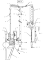
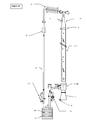
- the device ( Figure 1 ) for yielding one or more than one plant ingredient from a plant or plants and/or a part or parts of such a plant/plants by steam distillation comprises a steam generation unit 2, a distillation still 6, a head 9 of said distillation still provided with a thermometer 10, a condenser 11 and a collection device or vessel 12 for collecting said yield of plant ingredient(s).
- the distillation still 6 is (preferably, but not exclusively) shaped as a cylinder and has, in a preferred embodiment, a ratio of diameter (D) to height (H) of 1 : 25 to 1 : 2, even more preferred of 1 : 16 to 1 : 3.5, for example of 1 : 12 for operating the device under technical conditions or in the laboratory or of 1 : (at least 2) for operating the device in the fields.
- the generation of water vapour or steam may occur in a manner known per se from the prior art. Also the step of feeding the water vapour/steam generated into the device may be conducted in a per se known and conventional manner.
- a skilled person knows a great number of devices for generating steam, particularly at atmospheric pressure, in addition to devices to feed said steam into devices designed for special purposes.
- an external steam generator 2 of the type shown in Figure 1 as well as a direct steam feed line 3 is employed, as also shown in Figure 1 . Both means are subsequently described in detail.
- a steam generator 2 employed preferably in accordance with the present invention has a usual energy source 1 by which heat energy is applied to the water directly or indirectly whereby steam is generated.
- the energy source may be, for example, a heating jacket filled with a heating agent.
- the energy source may also be a heating muff or a heating rod. The latter devices are operated electrically and heat the water through the walls of the device.
- other energy sources may be employed as, for example, radiators. In this respect, the present invention is not at all restricted.
- An electrically operated ceramic rod heating the water, preferably desalted or de-ionized water, in a small cross-section of the device, for example in a glass tube connected to the overall water content of the device proved to be effective and is, hence, preferred.
- the steam generator 2 Via a filling funnel 0 for filling water into the device, the steam generator 2 is connected to the environment. Thereby, it is ensured that the device or plant is operated substantially at a pressure corresponding to the pressure of the environment.
- this is not compulsory: There may be applied pressures in the range of low sub-atmospheric pressure to low supra-atmospheric pressure.
- the steam generated in the above-described way in an efficient and energy-saving way is fed to the distillation still, preferably via in isolated direct steam feed line 3.
- Said direct steam feed line 3 may be separated from the distillation still by means of a shut-off valve.
- the cylindrical distillation still 6 is provided at its bottom end with a means 4 for releasing the pressure of the steam and a means 4b for controlling the flow rate.
- a means may be, in a particularly preferred embodiment of the invention, a steam pressure release space 4 as shown in detail in Figure 4 .
- a steam pressure release space 4 has a circular cross-section and is arranged concentrically to the axis of the distillation still 6 below said distillation still 6.
- the steam enters the steam pressure release space 4 via an inlet connected to the direct steam feed line 3 which has a relatively narrow cross-section and allows the steam to flow rapidly, and the steam pressure release space 4 is filled by steam successively.
- a pressure release occurs due to the fact that the steam pressure release space has a considerably larger cross-section than the direct steam feed line 3.
- Steam condensing to the walls of the steam pressure release space 4 transfers the heat contained therein to the walls and heats them successively.
- Condensate which is not heated and another time evaporated by further steam and, thereby, driven into the direction of the steam flow (i.e. upwards), flows downwards via a back flow condensate (reflux steam trap) outlet 4c arranged in the bottom part of the steam pressure release space into a back flow condensate vessel 5 arranged at the lower end of the steam pressure release space and connected via a suitable connection (e. g. via a ball-and-socket joint).
- a suitable connection e. g. via a ball-and-socket joint
- impingement plate 4a arranged concentrically to the axes of the steam pressure release space 4 and the distillation still 6 in said steam pressure release space 4.
- the impingement plate has the function to guide the steam to the outer walls and to thereby effect that a mixture of water and plant ingredients running down from the distillation still 6 evaporates another time and is driven upwards into the distillation still 6 again. It is prevented thereby that a proportion of the product corresponding to said mixture trickling down is lost in recovering the plant ingredient(s) and trickles down into the back flow condensate (reflux steam trap) vessel 5.
- the impingement plate 4a effects an excellent distribution of the steam in the whole upper part of the steam pressure release space 4 and, subsequently, a very uniform flow of the steam to the bottom screen 4b.
- the bottom screen 4b serves not only as a support for the layers of plants and/or parts of such plants, but also to a uniform distribution of the steam across the whole cross-section of the cylindrical distillation still 6.
- a preferred cylindrical distillation still 6 with isolation has a ratio of diameter (D) to height (H) in a certain range as indicated above. It turned out in the course of extensive experiments that an efficient and high yield extraction of plant ingredients cannot be achieved with a ratio D/H below said value. In the same way, a ratio D/H substantially exceeding the values mentioned-above will not result into a successful extraction of plant ingredients. Without wanting to be bound to a specific theory for this effect which could not yet be elucidated in detail, it is assumed that a value of the ratio D/H in the above-specified range has an effect on the flowing steam which is comparable to the effect of a chimney having a good "flue".
- D/H is, of course, dependent upon several parameters as, for example, the density of the packing of the plant material 7, the flow rate of the steam, the pressure and, of course, also upon the type of plant ingredients to be extracted. However, if the value is within the above-specified range, an efficient, gentle and complete recovery of the plant ingredients can surprisingly be achieved in a much shorter time than possible up to now.
- the distillation still 6 and, as indicated above, also further parts of the device/plant as, for example, the head 9 of the distillation still 6 and/or the uprising tube 20 and/or the bridge 21, is/are isolated against heat losses on its/their outer side in a preferred embodiment of the invention.
- a material is used which impairs the equilibrium steps of successive and repeated steps of condensation and evaporation of the water/steam and of the plant ingredient(s) as little as possible.
- the head 9 of the distillation still 6, the uprising tube 20 and the bridge 21 are provided on their inner wall facing to the uprising steam with a surface which has regularly arranged concave recesses over the whole surface.
- the recesses are applied on the inner side of the head 9 of the distillation still 6, the uprising tube 20 and the bridge 21 in a triangular arrangement with the aim of a closest-possible positioning thereof to each other.
- Such a triangular arrangement of the recesses particularly in those areas where one compartment of the apparatus is transitioning into another compartment, surprisingly promotes a smooth condensation of the steam containing plant ingredients.
- the plant ingredients are obtained in a higher purity, compared to distillation processes of the prior art, and their water content is substantially reduced: A clear condensate-product is obtained.
- Said recesses preferably have a diameter in the range of 2 to 5 mm and, even more preferably, have a distance to each other of between 5 to 10 mm. Even more preferably, the diameters and distances of the recesses may be larger at the trumpet-shaped transfer areas of the inlets and outlets of the devices than at the remaining walls of the devices.
- the axis of the uprising tube 20 and the axis of the bridge 21 are in an angle of from 120 to 140 ° to each other, more preferred in an angle of from 125 to 135 °.
- the condenser 11, to which the steam (generated as described above) containing the plant ingredients is supplied is a balloon condenser 11 having at least three balloons, preferably having at least five balloons.
- the balloon condenser 11 is closed (due to the possible sensitivity of the plant ingredients obtained) and, in accordance with another embodiment of the invention, is arranged in a falling arrangement, i. e. the vapour/steam flows from the bridge 21 in a downwardly falling direction.
- the condensate comprising water and plant ingredients is supplied to a receiving vessel 12, for receiving the plant ingredient(s) obtained.
- the collecting vessel 12 may have the usual shape, as it is known for receiving sensitive substances to a person skilled in this technical field.
- a skilled person when selecting the collecting vessel 12, will be capable to consider that the substances recovered and obtained will at least in part be light-sensitive substances and/or substances possibly being degraded under the influence of light.
- closed collecting vessels or light-protected collecting vessels or cooled collecting vessels will have to be provided.
- it turned out to be advantageous to provide a collecting vessel allowing recovering different fractions of the plant ingredients to be obtained for example a collecting vessel having different receiving vessels to be changed in the course of the process.
- Such collecting vessels are known to a skilled person, too.
- the receiving vessel 12 for recovering the plant ingredient(s) obtained is a device consisting of a settling vessel having a level control 16, a condensed water exit 15, a condensed oil exit 14 including an oil measuring tube 13 and an exit tap 17, wherein the settling vessel having a level control 16, the condensed water exit 15 and the condensed oil exit 14 including the oil measuring tube 13 are connected to each other in the form of a communicating tube system.
- a preferred device of this type is exemplarily shown in Figure 3 . In a particularly preferred embodiment, more than one of such devices may be used side by side or in sequence for different fractions of the condensate.
- the hollow bodies are connected at their respective bottom parts via a connecting line or connecting tube.
- the first tube considered in the flow direction of the condensate mixture recovered is arranged immediately below the high performance condenser and has, at its upper end, a tube portion having a relatively large diameter.
- the condensate mixture drops or preferably runs into said tube along the wall.
- the mixture is settled therein, i.e. a substantially slow flow of the liquid(s) occurs therein.
- the components may already be separated from each other in such a preferred receiving vessel, for example on the basis of their density:
- the plant ingredients to be extracted have a lower density than water and are found in the upper part of the liquid while the water flows downward within the extended part of this tube.
- the measuring tube 13 is found in this portion of the receiving vessel according to the invention and has a graduation known for the purpose of volume measurement. The volume amounts of the components of the condensate may be measured by this measuring tube after collecting and lowering the overfall 15.
- the intermediate portion of the receiving vessel 12 also consists of a tube-shaped hollow body for a level control. At its lower part, this tube is relatively largely extended in its cross-section in order to receive large volume amounts of condensate, for example large amounts of water in the starting phase of the process. From this portion of the tube having an enlarged cross-section and belonging to the receiving vessel 12, a third tube is branching off which is arranged at a place downstream to the entry of the condensate and serves the disposal of the condensed water.
- the receiving vessel preferred in accordance with the invention has an exit for condensed water at a suitable place 15 and has - at a place different from the above-mentioned place - a continuing outlet 19, preferable for a bigger amount of the components of the condensate which contain the plant ingredients to be extracted or even consist thereof, or after measurement an discontinuing outlet 14, or an outlet of plant ingredients there are heavier in density than water.
- the device according to the invention may comprise further means known to a skilled person and suitable for the purpose of recovering plant ingredients from plants and/or parts of such plants.
- the means can be adapted to specific purposes (e.g. the recovery of specific plant ingredients) and are selected by a skilled person in accordance with usual criteria.
- a device including a receiving vessel 12, the detailed construction of which may be derived from Figure 2 .
- Figure 2 those parts of the device where the water generation, distillation and/or extraction steps are carried out are omitted for convenience; these parts of the device may have the shape and construction as described above and shown exemplarily in the other Figures or may have any conventional shape and construction or may be a combination of both.
- the ball condenser 11 is shown which, at its top end, is connected to the distillation bridge 21. At its bottom end, the condenser 11 is connected, preferably is connected by an exactly vertical connection, in a usual way, for example by a ball-and-socket connection, to a receiving vessel 12.
- the receiving vessel 12 has a spherical or cylindrical shape and its volume, albeit not restricted, as may be appreciated by a skilled person, is between 10 ml and 100 ml in devices which are used in a laboratory scale of plant ingredient yielding.
- Such a spherical or cylindrical receiving vessel 12 serves the (at least intermediate) uptake of one plant ingredient or more than one plant ingredient produced and condensed in the condenser 11 located above the receiving vessel 12, as well as of additional amounts of water used in the process of the invention for distilling and/or extracting plant ingredient(s) from the plants treated in the device.
- the receiving vessel in further preferred embodiments of the invention, may be provided with a flask 17 for inert gas supply to the receiving vessel.
- a flask 17 for inert gas supply to the receiving vessel.
- protective gases may be oxygen-depleted air, pure nitrogen or noble gases, argon being preferred as the noble gas, optionally in combination with nitrogen or O 2 -depleted air.
- such gases may be provided at a temperature being below the temperature level of the liquid(s) when they enter the receiving vessel 12, for example (without restriction) below 10 °C, even more preferred below 5 °C.
- the protective (optionally low temperature) gas may be supplied to the receiving vessel by blowing it into the vessel onto the top liquid surface where it may overlay the liquid (if the gas is heavier than air), while a built-up of increased pressure is prevented by providing an additional siphon trap 18 allowing gas to escape from said receiving vessel.
- such protective gas may be supplied by blowing it, by means of a suitable tube (e. g. a glass tube) below the surface of the liquid contained in said receiving vessel 12 at a certain point of time.
- the protective gas is allowed to (at least partially) dissolve in the liquid and to move, by bubbling, through the liquid, thereby preventing any deleterious side reaction or decay reaction in the products and, simultaneously, entraining some of the water or of other volatile components and transporting it into the gas space above the liquid and, finally, through the siphon trap 18, out of the receiving vessel 12.
- a cooling effect can easily be achieved by blowing in cooled protective gas.
- a drain cock 19 In another preferred embodiment which may be provided together with the protective gas supply flask 17 or may be provided alone is a drain cock 19.
- the drain cock 19 may be provided at any location of the (preferably spherical) receiving vessel 12. Particularly preferred, however, is a drain cock 19 in the lower half or at the bottom side of the receiving vessel 12.
- the drain cock 19 at the bottom of the receiving vessel 12 allows a removal or draining of a fluid or liquid from the receiving vessel, preferably of one plant ingredient or more than one plant ingredient yielded from the process of the invention, particularly preferably of a plant ingredient or of several plant ingredients having a specific weight lighter that the water condensed.
- the receiving vessel 12 while connected at its top end to the connection to the condenser 11, is connected at its lower end to, and is in flow communication with, communicating vessels 16 which are adjustable in height for leveling the liquid (plant ingredient plus optional amounts of water) surface, allowing a measurement of the amount(s) of plant ingredient(s) obtained and removing water separated from the condensate contained in the receiving vessel 12.
- the communicating vessels 16 may comprise a scale pipe 13 allowing to measure the amount of components (either water or yielded plant ingredient(s)) contained in the liquid passing the scale pipe 13.
- the communication vessels 16 may further comprise, I another preferred embodiment of the invention, an outlet 14 for heavy components of the condensate, for example for a plant ingredient or for several plant ingredients the specific weight of which is heavier than water; this component/these components may flow to the bottom part of the communication vessels where they can be drained by opening the outlet 14.
- Another preferred embodiment of the device comprises, as a component or part of the communicating vessels 16, a water overfall 15 suitable for collecting high value hydrolate separately from condensed water and from plant ingredients.
- transitions are created, at the device' parts where a change of the free flow diameter occurs.
- Such transitions should offer the lowest-possible resistance to the steam flow and product flow.
- trumpet-shaped transitions at those areas. This can exemplarily be derived from Figures 1a and 1b and Figure 4 .
- the result is a remarkably better flow of the product stream and a product having a considerably higher product purity.
- it may be achieved that the product is substantially free of water and the oil content in the hydrolate (at condensed water after outlet 15) is lower.
- the device so far described to be used for yielding plant ingredients by distillation is used for a combined process of the type wherein a separation, by distillation, of plant ingredients from their mother plant(s) from a part or parts of such mother plant(s), on the one hand (for example by carrier steam distillation), and/or a separation, by extraction, of plant ingredients from their mother plant(s) or from parts of such mother plants, on the other hand, can be carried out.
- a separation, by distillation, of plant ingredients from their mother plant(s) from a part or parts of such mother plant(s), on the one hand for example by carrier steam distillation
- a separation, by extraction, of plant ingredients from their mother plant(s) or from parts of such mother plants on the other hand, can be carried out.
- several separate distillation and/or extraction steps may be conducted alternatively.
- Such separate distillation and/or extraction separation processes may be carried out alternatively or successively.
- a distillation process step before conducting an extraction with solvents results into a better chemical opening of the plant oil secretion cells within the plant(s) or part(s) of plants by swelling.
- solvents for example with ethanol
- a separation by using solvents before conducting a distillation increases the yield of the essential oil(s).
- an extraction with a solvent or with solvents or a steam distillation process or a combination of both may be conducted.
- the above-described device for yielding plant ingredients, alternatively or successively by distillation and/or extraction comprises means for changing the device parts from distillation to extraction or from extraction to distillation by turning on a turn-table means or by shifting on a track means.
- the distillation means and/or the extraction means optionally together with their connected downstream device part(s), is/are arranged on a turntable in a predetermined order. They are capable of being disconnected from the ready-to-use device by raising or lowering them, of being exchanged by the respective device planned to be used next by turning the turntable, and of being connected again to the ready-to-use device by raising or lowering them.
- the overall distillation and/or extraction device may be prepared for the next process step.
- a linear arrangement of such means is possible.
- the exchange of device parts or means is not conducted by turning, but is conducted by shifting said means, for example on a usual track system known to a skilled person for such purposes.
- a device designed like described before does not only allow a combined distillation/extraction operation of the plant, but also allows the discontinuous, or batch-type, operation of a distillation plant or of an extraction plant or of a combined distillation/extraction plant: Desired distillation units or extraction units or units of both types may be arranged on a turntable system (to be operated by turning) or on a shifting or track system (to be operated by shifting) in a desired order and may be connected to the overall plant one after the other or simultaneously. To give just one example, such turn or shift process steps may be conducted hydraulically or pneumatically, preferably.
- this allows for a batch-type operation in such a manner that one distillation unit and/or one extraction unit is operated under distillation and/or extraction conditions, while the respective other one is emptied, cleaned and/or newly filled with plant material, and is subsequently connected to the plant and, thereby, takes the place of the previous distillation unit and/or extraction unit in the course of the distillation and/or extraction process.
- the advantages of the process according to the invention as well as of the device according to the invention as described above are apparent: In contrast to existing processes and devices, the energy applied is used in an optimum manner; energy savings are in a range of 35 to 45 %.
- the device by allowing different parts and means of the device to be combined, allows a quick change of the operation alternatives by rapidly changing different means against each other, as well as a rapid exchange of used plant material (already subjected to distillation and/or extraction step(s)) against fresh plant material to be subjected to an appropriate treatment.
- the present invention provides an effective filling and discharging device, which allows for shortest-possible changes of the device parts.
- a rapid filling and discharging procedure makes the work during the distillation and extraction processes easier and promotes the occurrence of a large number of process cycles.
- Easy filling is effected by means of a funnel placed at the head of the device below the comminuting device. The plant material to be subjected to distillation/extraction falls down from the funnel into the distillation still in a loose and uniform manner.
- the bottom sieve removable from the lower part of distillation still by lowering it makes free the drop bottom of the distillation still completely, with the aim of allowing the distillation still to release the exhausted plant material from the still in one step after a side turn.
- a vessel prepared for said purpose or a screw conveyor removes the material away from the working area.
- the distillation still is returned to the original position, the bottom sieve actuated hydraulically and including the steam inlet is lifted again, and the distillation still is closed sealingly at its upper and lower ends automatically by a silicon rubber sealing rind, for example.
- distillation time is not only independent of the amount of plant material filled into the distillation still, but is also considerably shorter than with known processes: Due to a consequent use of all thermodynamic possibilities, the distillation times are below one hour, in some examples in the range of 20 to 30 minutes, compared to two to three hours in the prior art. Hence, the process according to the present invention is quicker than conventional processes by a factor of 3 to 6, depending upon the course of the process and the embodiment of the device.
- test device can be converted or scaled up to a technical device without any problems and may also be converted to a plant of an industrial scale. No adaptation of operation and process parameters to a change of the dimension of the device is necessary.
- the desired products are recovered in high yield and purity without side products or decay products detrimental to the quality.
- the only side products are the residual parts of plants which where contacted with water, and water itself.
- the vegetable waste is no chemistry waste (in contrast to parts of plants in accordance with the prior art which where contacted with solvents).
- the process is ecologically compatible in each respect.
- the invention is further exemplified by the following examples.
- the examples are preferred embodiments of the invention and should not be considered to restrict the invention.
- Selected plants of lemon balm grown up organically were harvested at a predetermined harvesting time speedily and were cut with an air cutter (field harvester) to an appropriate size without pressing the plant material.
- the plant material was transported to the distillation still and was directly supplied to the still soon after arrival without pressing the material, loosely and under its own weight.
- an essential oil having a high citral content 47.22 % of neral/geranial
- a low content of skin-compatible citronellal (0.51 %) and rich of sesquiterpenes (20.91 % of ⁇ -caryophyllene, 10.75 % of germacrene)
- lemon balm having the chemotype "Sommerol" (“summer oil")
- the flavour was dry and bloomy, and the oil contains cosmetically effective components and has good medical virus-inhibiting and bactericide properties.
- the essential oil obtained from the plant material having the chemotype "Subentsommeröl" (“late summer oil”) harvested in August has a larger content of citronellal and limonene (10.35 %) and has a flavour more lemon-like and fresh and has an even higher content of citral of up to 72.74 %.
- Selected carrier plants of carrot seeds grown up organically were harvested in a dry and ripe (oxide-red/red-brown) condition by using a harvester-thresher and were freshly ground coarsely above the upper entrance opening of the distillation still (roller mill 0.1 to 1 mm particle size).
- the coarsely ground plant material 50 kg was supplied directly to the distillation still and was distilled speedily.
- the steam supplied according to the plant design and size automatically adapted exactly to the conditions existing in the column. No further adaptation was necessary, neither due to plant species nor part of a plant, nor density, nor wetness nor fill amount. Hence, in the course of the real extraction phase (first 10 minutes), no restraint and no interference was occurring. Already after 1 hour, a clear essential oil distillate (250 ml) could be obtained from the separation vessel. This essential oil was further processed under a layer of protection gas (e.g. argon). A content of carotol of up to 50 % and of daucol of up to 2 % could be determined in the essential oil.
- protection gas e.g. argon
- Selected carrier plants of coriander seeds grown up organically were harvested in a dry and ripe (red-brown) condition by using a mobile harvester-thresher and were freshly ground coarsely above the upper entrance opening of the distillation still (roller mill 0.2 to 2 mm particle size).
- the coarsely ground plant material 50 kg was supplied directly to the distillation still and was distilled speedily.
- the steam supplied according to plant design and size automatically adapted exactly to the conditions existing in the column. No further adaptation was necessary, neither due to the plant species nor part of a plant, nor density, nor wetness nor fill amount. Hence, in the course of the real extraction phase (first 15 minutes), no restraint and no interference was occurring. Already after 1 hour, a clear essential oil distillate (300 ml) could be obtained from the separation vessel. This essential oil was further processed under a layer of protection gas (e.g. argon). A content of linalool of up to 75 % and coriandrine (furanocoumarines) were found in the essential oil.
- protection gas e.g. argon
- Selected plants of immortelle grown up organically was harvested at a predetermined harvesting time speedily and was cut with an air cutter (field harvester) to an appropriate size of the blossom shoots without pressing the plant material.
- the plant material was transported to the distillation still in small lots and was directly supplied to the still soon after arrival without pressing the material, loosely and under its own weight.
- the steam supplied according to plant design and size automatically adapted exactly to the conditions existing in the column. No further adaptation was necessary, neither due to plant species nor part of a plant, nor density, nor wetness nor fill amount. (Supplied material: 12 kg). After approx. 45 minutes, the essential oil was obtained completely (25 ml) and settled in the separation vessel in the form of a clear layer. It is further processed from there under a protective gas speedily.
- a composition containing 500 Grams (g) of cananga blossoms was uniformly mixed with 50 g of xylite/lignite with stirring, and the mixture was supplied to the distillation still immediately thereafter loosely and freely falling, and was subjected to distillation.
- the material supplied remained at indispensable steam movement rate completely and yielded a clear essential oil condensate having a high content of aromatically active oxidized monoterpenes and sesquiterpenes.
- a composition containing 500 g of carrot seeds (finely ground) was uniformly mixed with 100 g of chopped xylite with stirring, and the mixture was supplied to the distillation still immediately thereafter loosely and freely falling, and was subjected to distillation.
- the material supplied remained at indispensable steam movement rate completely and yielded a clear, fine-aromatic essential oil condensate having a high content of carotol.
- a composition of 1000 g of Atlas Cedar recalcitrant compounds (saw dust) was mixed with 100 g of vermiculite uniformly under stirring, and the mixture was filled into the distillation still immediately thereafter loosely and in a free-falling condition and was then subjected to distillation. Since the wooden material did not absorb any condensed water, the natural reflux is absorbed by the vermiculite material and is again evaporated when further steam is supplied.
- the material supplied remained at indispensable steam movement rate completely and yielded a clear, fine-aromatic essential oil condensate having a high clearance, purity and rare trace components.
- a composition of 1000 g of roots of angelica (freshly cut slowly by a slitter into slices) was mixed with 500 g of vermiculite uniformly under stirring, and the mixture was filled into the distillation still immediately thereafter loosely and in a free-falling condition and was then subjected to distillation. Since the root material was swelling strongly due to a release of plant-own water after having been contacted by the steam and thereby looses its stability, a structure stability was provided by the vermiculite. The steam kept at its indispensable movement rate kept its outstanding properties as a solvent, and no obstructive reflux and no bulk packing occurred. The essential oil thus obtained had no turbidity, what was a sign of a lower water content and of a high quality standard.
- the invention generally relates to an accelerate process for yielding one or several plant ingredient(s) from one or several plant(s) and/or from one or several part(s) of such plants, wherein
- the process comprises that the process pressure is in a range of 1.013 ⁇ 0.1 bar.
- Another preferred embodiment of the invention comprises a process, wherein the steam is generated externally and is supplied to the layer of plant(s) and/or part(s) of plant(s) from the lower end of the layer in an uprising flow direction.
- Another preferred embodiment of the invention comprises a process, wherein the steam flow speed is in a range of from 0.1 to 0.3 cm/s.
- Another preferred embodiment of the invention comprises a process, wherein wherein a steamy/vaporous solution of the plant ingredient(s) is formed from one or several of the steam-soluble plant ingredient(s) and water, and/or an aqueous suspension of the plant ingredient(s) is formed from one or several of the water-insoluble plant ingredient(s) and water.
- Another preferred embodiment of the invention comprises a process, wherein one or several mineral additive(s ) is/are added to the layer of plant(s) and/or part(s) of plant(s), preferably wherein one or several mineral additive(s) is/are added in a uniform distribution, more preferably wherein one or several mineral additives is/are added which are selected from the group consisting of silicates, volcanic minerals and fibrous fossile plant materials, more preferably wherein one or several mineral additives are added which are selected from the group consisting of montmorillonite, vermiculite, perlites and xylite/lignite, and most preferred wherein one or several of the above mineral additives are added in an amount of from 10 to 50 % by weight, based on the overall weight of the fill.
- Another preferred embodiment of the invention comprises a process, wherein the water condensing to the plant(s) and/or to the part(s) of plant(s) drives out the one or several plant ingredient(s) by diffusion from the cells containing the plant ingredient(s).
- Another preferred embodiment of the invention comprises a process, wherein the water condensing to the plant(s) and/or to the part(s) of plant(s) is maintained at a temperature close to the boiling point by heat transported by successional steam.
- Another preferred embodiment of the invention comprises a process, wherein the plant(s) or parts of plant(s) are selected from the group consisting of whole plants, leaves of plants, fruits of plants, stems of plants, seeds of plants, blossoms of plants and roots of plants.
- Another preferred embodiment of the invention comprises a process, wherein plant ingredients are yielded from fresh plant(s) and/or part(s) of plant(s) and/or from withered plant(s) and/or part(s) of plant(s).
- Another preferred embodiment of the invention comprises a process, wherein the recesses on the inner surface of the head of the distillation still, the ascending pipe and the bridge have a diameter in the range of from 2 to 5 mm and/or have a distance to each other in the range of from 5 to 10 mm.
- the invention also relates to an apparatus for yielding one or several plant ingredient(s) from a plant or from plants or from a part of a plant or from parts of a plant or of plants by steam/water vapour distillation, said apparatus comprising a steam generation unit (2), a distillation still (6), a head (9) of the distillation still (6) provided with a thermometer (10), a condenser (11) and a receiving vessel (12) for collecting the plant ingredient(s) obtained; wherein
- a preferred embodiment of the invention relates to an apparatus, wherein the recesses on the inner surface of the head (9) of the distillation still (6), the ascending pipe (20) and the bridge (21) have a diameter in the range of from 2 to 5 mm and/or have a distance to each other in the range of from 5 to 10 mm and/or are arranged in a triangular arrangement.
- Another preferred embodiment of the invention relates to an apparatus, wherein the steam generator (2) is an external steam generator having a direct steam supply via a supply pipe (3) into the cylinder-shaped distillation still (6) from its bottom end.
- distillation still (6) has a sphere shape or has a cylinder shape (said cylinder having a round, triangle, quadrangle or multi-angle diameter) or has a cone shape and is provided at its bottom end with a means (4) for relieving the pressure of the steam and with a means (4b) for controlling the flow speed.
- Another preferred embodiment of the invention relates to an apparatus, wherein the means (4b) for controlling the flow speed is a sieve plate (4b) located at the bottom end of the distillation still (6).
- Another preferred embodiment of the invention relates to an apparatus, wherein the axes of the ascending pipe (20) and of the bridge (21) are arranged in an angle being within a range of from 120 ° to 140 °, preferably in an angle being within a range of from 125 ° to 135 °.
- Another preferred embodiment of the invention relates to an apparatus, wherein the distillation still (6) and preferably also the head (9) of the distillation still (6), the ascending pipe (20) and the bridge (21) singly or all together is/are provided with an isolation against a loss of heat, preferably on its/their outer side(s).
- the receiving vessel (12) for collecting the plant ingredient(s) obtained is an arrangement consisting of a settling vessel having a level control (16), a condensed water exit (15), a condensed oil exit (14) and (19) including an oil measuring tube (13) and an exit tap (14), wherein the settling vessel having a level control (16), the condensed water exit (15) and the condensed oil exit (14) and (19) including the oil measuring tube (13) are connected to each other in the form of a communicating tube system.
- Another preferred embodiment of the invention relates to an apparatus, wherein the apparatus may be provided with a protecting gas, preferably wherein the apparatus may be provided with a protecting gas in the area of the condenser (11) and/or in the area of the collecting vessel (12), more preferably wherein the apparatus may be provided with a protecting gas in the area downstream of the condenser (11).
- the receiving vessel (12) for collecting the plant ingredient(s) obtained comprises a protective gas supply (17) optionally comprising a gas supply tube or capillary, a siphon trap (18), a draincock 19 for draining liquid, a scale pipe (measuring pipe) 13, an outlet (14) at the lower end thereof, communicating vessels (16) adjustable in height for levelling the fluid surface in the receiving vessel (12) and a water overfall (15).
- a protective gas supply (17) optionally comprising a gas supply tube or capillary, a siphon trap (18), a draincock 19 for draining liquid, a scale pipe (measuring pipe) 13, an outlet (14) at the lower end thereof, communicating vessels (16) adjustable in height for levelling the fluid surface in the receiving vessel (12) and a water overfall (15).
- Another preferred embodiment of the invention relates to an apparatus, wherein the apparatus additionally comprises means for a combined alternative or successive operation of the apparatus for yielding plant ingredient(s) by distillation and extraction.
- Another preferred embodiment of the invention relates to an apparatus, wherein the means for a combined alternative or successive operation of the apparatus for yielding plant ingredient(s) by distillation and extraction is a means for exchanging the apparatus parts for distillation or extraction by turning on a turn-table means or by shifting on a track means.
- Another preferred embodiment of the invention relates to an apparatus, said apparatus further comprising means for exchanging several distillation means and/or extraction means in an alternating distillation and/or extraction operation by exchanging the apparatus parts for distillation and/or for extraction by turning on a turn-table means or by shifting on a track means.
- Another preferred embodiment of the invention relates to an apparatus, wherein the exchange of the apparatus parts for a distillation and/or extraction operation is carried out hydraulically or pneumatically.
- Another preferred embodiment of the invention relates to an apparatus, said apparatus allowing a batch-wise operation of such a kind that one distillation device is operated in the distillation mode and/or one extraction device is operated in the extraction mode, while the respective other device is emptied, cleaned and/or is newly filled with plant material and subsequently takes the place of the respective other distillation device and/or extraction device in the distillation and/or extraction mode.
Landscapes
- Chemical & Material Sciences (AREA)
- Life Sciences & Earth Sciences (AREA)
- Engineering & Computer Science (AREA)
- Health & Medical Sciences (AREA)
- Nutrition Science (AREA)
- Food Science & Technology (AREA)
- Polymers & Plastics (AREA)
- Chemical Kinetics & Catalysis (AREA)
- Oil, Petroleum & Natural Gas (AREA)
- Wood Science & Technology (AREA)
- Organic Chemistry (AREA)
- Fats And Perfumes (AREA)
Priority Applications (1)
| Application Number | Priority Date | Filing Date | Title |
|---|---|---|---|
| EP09169271A EP2294931A1 (de) | 2009-09-02 | 2009-09-02 | Verbessertes Verfahren und verbesserte Vorrichtung für ertragreiche Pflanzenbestandteile |
Applications Claiming Priority (1)
| Application Number | Priority Date | Filing Date | Title |
|---|---|---|---|
| EP09169271A EP2294931A1 (de) | 2009-09-02 | 2009-09-02 | Verbessertes Verfahren und verbesserte Vorrichtung für ertragreiche Pflanzenbestandteile |
Publications (1)
| Publication Number | Publication Date |
|---|---|
| EP2294931A1 true EP2294931A1 (de) | 2011-03-16 |
Family
ID=41651359
Family Applications (1)
| Application Number | Title | Priority Date | Filing Date |
|---|---|---|---|
| EP09169271A Withdrawn EP2294931A1 (de) | 2009-09-02 | 2009-09-02 | Verbessertes Verfahren und verbesserte Vorrichtung für ertragreiche Pflanzenbestandteile |
Country Status (1)
| Country | Link |
|---|---|
| EP (1) | EP2294931A1 (de) |
Cited By (25)
| Publication number | Priority date | Publication date | Assignee | Title |
|---|---|---|---|---|
| CN102974119A (zh) * | 2012-12-18 | 2013-03-20 | 华东理工大学 | 一种气体冷凝分级装置及应用方法 |
| DE102012006145B4 (de) * | 2011-05-13 | 2013-07-25 | Helmut Rausche | Verfahren zur Gewinnung von Aromen aus Biomaterial |
| WO2013192415A3 (en) * | 2012-06-21 | 2014-02-13 | Aromator Llc | Distillation apparatus for extraction of essential oils and hydrosols from plant matter within a capsule |
| FR3010324A1 (fr) * | 2013-09-06 | 2015-03-13 | Schmidt Laurent Dreyfus | Appareil d'extraction des essences de vegetaux |
| RU169872U1 (ru) * | 2016-09-19 | 2017-04-04 | Дмитрий Владимирович Щукин | Дистиллятор колонного типа |
| CN106885723A (zh) * | 2017-04-06 | 2017-06-23 | 重庆市食品药品检验检测研究院 | 一种食品中丙酸类添加剂的提取装置 |
| RU173779U1 (ru) * | 2017-03-02 | 2017-09-11 | Роман Олегович Панамарев | Дистиллятор колонного типа |
| CN108641820A (zh) * | 2018-07-17 | 2018-10-12 | 济南九州富得香料有限责任公司 | 精油提取装置 |
| RU187827U1 (ru) * | 2018-10-09 | 2019-03-19 | Общество с ограниченной ответственностью "Вейн" | Дистиллятор колонного типа с тэном |
| CN110035809A (zh) * | 2016-11-10 | 2019-07-19 | 拉米罗·塞尼奥雷特·韦尔杜戈 | 蒸汽蒸馏提取有机原材料中挥发油的设备和内部蒸馏方法 |
| US10406451B2 (en) | 2017-08-24 | 2019-09-10 | Lab Society Llc | High efficiency distillation head and methods of use |
| RU194092U1 (ru) * | 2019-05-07 | 2019-11-28 | Анатолий Николаевич Гайнутдинов | Дистиллятор колонного типа |
| US10751638B2 (en) | 2017-03-03 | 2020-08-25 | Lab Society Llc | High efficiency distillation head and methods of use |
| CN111849641A (zh) * | 2020-07-21 | 2020-10-30 | 宋如心 | 一种植物精油制备工艺 |
| RU2739919C1 (ru) * | 2020-01-10 | 2020-12-29 | Роман Олегович Панамарев | Универсальный дистиллятор трансформер |
| CN113403144A (zh) * | 2021-06-22 | 2021-09-17 | 杨思军 | 一种植物汁液萃取装置 |
| CN113559550A (zh) * | 2021-08-26 | 2021-10-29 | 山西大学 | 黄花菜中黄酮的提取方法和提取装置 |
| CN113940445A (zh) * | 2021-10-26 | 2022-01-18 | 深圳市真味生物科技有限公司 | 一种电子雾化液生产加工用原液提取设备 |
| CN114618184A (zh) * | 2022-01-27 | 2022-06-14 | 江西江中济海制药有限责任公司 | 一种用于低含油量植物挥发油的蒸汽冷凝装置和收集系统 |
| CN115282641A (zh) * | 2022-07-18 | 2022-11-04 | 厦门烟草工业有限责任公司 | 油水分离装置 |
| CN115400443A (zh) * | 2022-09-20 | 2022-11-29 | 安徽碳鑫科技有限公司 | 一种用于甲醇生产的蒸馏提纯设备 |
| RU217982U1 (ru) * | 2023-03-16 | 2023-04-28 | Анатолий Николаевич Гайнутдинов | Бытовой дистиллятор |
| CN116036626A (zh) * | 2022-11-22 | 2023-05-02 | 安徽海华科技集团有限公司 | 一种反应原料快速高效脱水系统 |
| CN116536110A (zh) * | 2023-05-08 | 2023-08-04 | 浙江茶博士生物科技有限公司 | 一种茶叶精油蒸馏提取设备 |
| WO2024250623A1 (zh) * | 2023-06-05 | 2024-12-12 | 江西海瑞天然植物有限公司 | 一种用于水蒸气芳香精油蒸馏设备 |
Citations (6)
| Publication number | Priority date | Publication date | Assignee | Title |
|---|---|---|---|---|
| GB889157A (en) * | 1959-01-16 | 1962-02-07 | Gen Electric | Improvements in condensing surface structures particularly for use in distillation apparatus |
| JPH10244250A (ja) * | 1997-02-28 | 1998-09-14 | Mito Rika Glass:Kk | 非沸騰式蒸留精製装置 |
| DE19804010A1 (de) | 1998-02-02 | 1999-08-12 | Bayerische Landesanstalt Fuer | Verfahren und Vorrichtung zur Gewinnung von Pflanzen-Inhaltsstoffen |
| WO2002072743A1 (en) * | 2001-03-13 | 2002-09-19 | Council Of Scientific And Industrial Research | A simple portable mini distillation apparatus for the production of essential oils and hydrosols |
| US20020148601A1 (en) * | 2000-12-30 | 2002-10-17 | Martin Roos | Apparatus for accelerating condensation with the aid of structured surfaces |
| WO2008068757A1 (en) * | 2006-12-05 | 2008-06-12 | Moshe Balass | Distillation apparatus for extraction of essential oils from plant matter |
-
2009
- 2009-09-02 EP EP09169271A patent/EP2294931A1/de not_active Withdrawn
Patent Citations (6)
| Publication number | Priority date | Publication date | Assignee | Title |
|---|---|---|---|---|
| GB889157A (en) * | 1959-01-16 | 1962-02-07 | Gen Electric | Improvements in condensing surface structures particularly for use in distillation apparatus |
| JPH10244250A (ja) * | 1997-02-28 | 1998-09-14 | Mito Rika Glass:Kk | 非沸騰式蒸留精製装置 |
| DE19804010A1 (de) | 1998-02-02 | 1999-08-12 | Bayerische Landesanstalt Fuer | Verfahren und Vorrichtung zur Gewinnung von Pflanzen-Inhaltsstoffen |
| US20020148601A1 (en) * | 2000-12-30 | 2002-10-17 | Martin Roos | Apparatus for accelerating condensation with the aid of structured surfaces |
| WO2002072743A1 (en) * | 2001-03-13 | 2002-09-19 | Council Of Scientific And Industrial Research | A simple portable mini distillation apparatus for the production of essential oils and hydrosols |
| WO2008068757A1 (en) * | 2006-12-05 | 2008-06-12 | Moshe Balass | Distillation apparatus for extraction of essential oils from plant matter |
Non-Patent Citations (1)
| Title |
|---|
| DATABASE WPI Week 199847, Derwent World Patents Index; AN 1998-550181, XP002568643 * |
Cited By (34)
| Publication number | Priority date | Publication date | Assignee | Title |
|---|---|---|---|---|
| DE102012006145B4 (de) * | 2011-05-13 | 2013-07-25 | Helmut Rausche | Verfahren zur Gewinnung von Aromen aus Biomaterial |
| WO2013192415A3 (en) * | 2012-06-21 | 2014-02-13 | Aromator Llc | Distillation apparatus for extraction of essential oils and hydrosols from plant matter within a capsule |
| CN104812453A (zh) * | 2012-06-21 | 2015-07-29 | 阿罗马托尔有限责任公司 | 用于从容器中的植物物质提取精油和水溶胶的蒸馏装置 |
| US9956501B2 (en) | 2012-06-21 | 2018-05-01 | Aromator Llc | Distillation apparatus for extraction of essential oils and hydrosols from plant matter within a capsule |
| US10569193B2 (en) | 2012-06-21 | 2020-02-25 | Aromator Llc | Distillation method for extraction of essential oils and hydrosols from plant matter within a capsule |
| CN102974119B (zh) * | 2012-12-18 | 2015-04-08 | 华东理工大学 | 一种气体冷凝分级装置及应用方法 |
| CN102974119A (zh) * | 2012-12-18 | 2013-03-20 | 华东理工大学 | 一种气体冷凝分级装置及应用方法 |
| FR3010324A1 (fr) * | 2013-09-06 | 2015-03-13 | Schmidt Laurent Dreyfus | Appareil d'extraction des essences de vegetaux |
| RU169872U1 (ru) * | 2016-09-19 | 2017-04-04 | Дмитрий Владимирович Щукин | Дистиллятор колонного типа |
| CN110035809A (zh) * | 2016-11-10 | 2019-07-19 | 拉米罗·塞尼奥雷特·韦尔杜戈 | 蒸汽蒸馏提取有机原材料中挥发油的设备和内部蒸馏方法 |
| CN110035809B (zh) * | 2016-11-10 | 2022-01-25 | 拉米罗·塞尼奥雷特·韦尔杜戈 | 蒸汽蒸馏提取有机原材料中挥发油的设备和内部蒸馏方法 |
| RU173779U1 (ru) * | 2017-03-02 | 2017-09-11 | Роман Олегович Панамарев | Дистиллятор колонного типа |
| US10751638B2 (en) | 2017-03-03 | 2020-08-25 | Lab Society Llc | High efficiency distillation head and methods of use |
| CN106885723A (zh) * | 2017-04-06 | 2017-06-23 | 重庆市食品药品检验检测研究院 | 一种食品中丙酸类添加剂的提取装置 |
| US10406451B2 (en) | 2017-08-24 | 2019-09-10 | Lab Society Llc | High efficiency distillation head and methods of use |
| CN108641820A (zh) * | 2018-07-17 | 2018-10-12 | 济南九州富得香料有限责任公司 | 精油提取装置 |
| RU187827U1 (ru) * | 2018-10-09 | 2019-03-19 | Общество с ограниченной ответственностью "Вейн" | Дистиллятор колонного типа с тэном |
| RU194092U1 (ru) * | 2019-05-07 | 2019-11-28 | Анатолий Николаевич Гайнутдинов | Дистиллятор колонного типа |
| RU2739919C1 (ru) * | 2020-01-10 | 2020-12-29 | Роман Олегович Панамарев | Универсальный дистиллятор трансформер |
| CN111849641A (zh) * | 2020-07-21 | 2020-10-30 | 宋如心 | 一种植物精油制备工艺 |
| CN113403144B (zh) * | 2021-06-22 | 2022-11-18 | 浙江顶亨生物科技有限公司 | 一种植物汁液萃取装置 |
| CN113403144A (zh) * | 2021-06-22 | 2021-09-17 | 杨思军 | 一种植物汁液萃取装置 |
| CN113559550A (zh) * | 2021-08-26 | 2021-10-29 | 山西大学 | 黄花菜中黄酮的提取方法和提取装置 |
| CN113940445A (zh) * | 2021-10-26 | 2022-01-18 | 深圳市真味生物科技有限公司 | 一种电子雾化液生产加工用原液提取设备 |
| CN114618184A (zh) * | 2022-01-27 | 2022-06-14 | 江西江中济海制药有限责任公司 | 一种用于低含油量植物挥发油的蒸汽冷凝装置和收集系统 |
| CN114618184B (zh) * | 2022-01-27 | 2024-04-16 | 江西南昌济生制药有限责任公司 | 一种用于低含油量植物挥发油的蒸汽冷凝装置和收集系统 |
| CN115282641A (zh) * | 2022-07-18 | 2022-11-04 | 厦门烟草工业有限责任公司 | 油水分离装置 |
| CN115400443A (zh) * | 2022-09-20 | 2022-11-29 | 安徽碳鑫科技有限公司 | 一种用于甲醇生产的蒸馏提纯设备 |
| CN115400443B (zh) * | 2022-09-20 | 2023-04-18 | 安徽碳鑫科技有限公司 | 一种用于甲醇生产的蒸馏提纯设备 |
| CN116036626A (zh) * | 2022-11-22 | 2023-05-02 | 安徽海华科技集团有限公司 | 一种反应原料快速高效脱水系统 |
| CN116036626B (zh) * | 2022-11-22 | 2023-09-29 | 安徽海华科技集团有限公司 | 一种反应原料快速高效脱水系统 |
| RU217982U1 (ru) * | 2023-03-16 | 2023-04-28 | Анатолий Николаевич Гайнутдинов | Бытовой дистиллятор |
| CN116536110A (zh) * | 2023-05-08 | 2023-08-04 | 浙江茶博士生物科技有限公司 | 一种茶叶精油蒸馏提取设备 |
| WO2024250623A1 (zh) * | 2023-06-05 | 2024-12-12 | 江西海瑞天然植物有限公司 | 一种用于水蒸气芳香精油蒸馏设备 |
Similar Documents
| Publication | Publication Date | Title |
|---|---|---|
| EP2294931A1 (de) | Verbessertes Verfahren und verbesserte Vorrichtung für ertragreiche Pflanzenbestandteile | |
| US8445034B1 (en) | Systems and methods for producing organic cannabis tincture | |
| US9937218B2 (en) | Systems and methods for cannabinoid and terpene extraction and purification | |
| Ren et al. | Growth rate rather than growing season length determines wood biomass in dry environments | |
| Milojević et al. | Kinetics of distillation of essential oil from comminuted ripe juniper (Juniperus communis L.) berries | |
| Bocevska et al. | Supercritical CO2 extraction of essential oil from yarrow | |
| Perakis et al. | Supercritical fluid extraction of black pepper oil | |
| Brunner | Supercritical fluids: technology and application to food processing | |
| CA1291360C (en) | Process for the production of citrus flavor and aroma compositions | |
| Bensebia et al. | Supercritical CO2 extraction of rosemary: Effect of extraction parameters and modelling | |
| Lawrence | The isolation of aromatic materials from natural plant products | |
| IE881476L (en) | Commercially processed orange juice products having a more¹hand-squeezed character | |
| Anbalagan et al. | Prelusive scale extraction of mangiferin from Mangifera indica leaves: Assessing solvent competency, process optimization, kinetic study and diffusion modelling | |
| Chhouk et al. | Supercritical carbon dioxide-mediated hydrothermal extraction of bioactive compounds from Garcinia Mangostana pericarp | |
| JPH01117769A (ja) | 一層大きい手絞り特性を有する商業的供給ジュースを得る方法 | |
| Koul et al. | Steam distillation of lemon grass (Cymbopogon spp.) | |
| Chovanec et al. | Is There Opium Here?–Analysis of Cypriot Base Ring Juglets from Tel Beth-Shemesh, Israel | |
| US10471113B1 (en) | Producing cannabis extracts via selective decarboxylation | |
| WO2014103596A1 (ja) | ハーブ抽出組成物 | |
| AU756005B2 (en) | Method and device for extracting plant ingredients | |
| Yoswathana et al. | Optimization of subcritical ethanol extraction for xanthone from mangosteen pericarp | |
| CN106957766A (zh) | 青稞酒酿酒方法 | |
| Pavlić et al. | Extraction of minor compounds (chlorophylls and carotenoids) from yarrow–rose hip mixtures by traditional versus green technique | |
| CN113088400A (zh) | 一种芳香植物中香气物质的提取装置 | |
| NO158444B (no) | Fremgangsmaate for fremstilling av et citrusaroma- og smakskondensat. |
Legal Events
| Date | Code | Title | Description |
|---|---|---|---|
| PUAI | Public reference made under article 153(3) epc to a published international application that has entered the european phase |
Free format text: ORIGINAL CODE: 0009012 |
|
| AK | Designated contracting states |
Kind code of ref document: A1 Designated state(s): AT BE BG CH CY CZ DE DK EE ES FI FR GB GR HR HU IE IS IT LI LT LU LV MC MK MT NL NO PL PT RO SE SI SK SM TR |
|
| AX | Request for extension of the european patent |
Extension state: AL BA RS |
|
| 17P | Request for examination filed |
Effective date: 20110916 |
|
| 17Q | First examination report despatched |
Effective date: 20111128 |
|
| STAA | Information on the status of an ep patent application or granted ep patent |
Free format text: STATUS: THE APPLICATION HAS BEEN WITHDRAWN |
|
| 18W | Application withdrawn |
Effective date: 20120330 |