EP2294934B1 - Insertion de segments de filtre dans des boudins de filtre - Google Patents
Insertion de segments de filtre dans des boudins de filtre Download PDFInfo
- Publication number
- EP2294934B1 EP2294934B1 EP10175229.3A EP10175229A EP2294934B1 EP 2294934 B1 EP2294934 B1 EP 2294934B1 EP 10175229 A EP10175229 A EP 10175229A EP 2294934 B1 EP2294934 B1 EP 2294934B1
- Authority
- EP
- European Patent Office
- Prior art keywords
- filter segments
- groups
- filter
- stream
- axially
- Prior art date
- Legal status (The legal status is an assumption and is not a legal conclusion. Google has not performed a legal analysis and makes no representation as to the accuracy of the status listed.)
- Not-in-force
Links
Images




Classifications
-
- A—HUMAN NECESSITIES
- A24—TOBACCO; CIGARS; CIGARETTES; SIMULATED SMOKING DEVICES; SMOKERS' REQUISITES
- A24D—CIGARS; CIGARETTES; TOBACCO SMOKE FILTERS; MOUTHPIECES OF CIGARS OR CIGARETTES; MANUFACTURE OF TOBACCO SMOKE FILTERS OR MOUTHPIECES
- A24D3/00—Tobacco smoke filters, e.g. filter tips or filtering inserts; Filters specially adapted for simulated smoking devices; Mouthpieces of cigars or cigarettes
- A24D3/02—Manufacture of tobacco smoke filters
- A24D3/0229—Filter rod forming processes
-
- A—HUMAN NECESSITIES
- A24—TOBACCO; CIGARS; CIGARETTES; SIMULATED SMOKING DEVICES; SMOKERS' REQUISITES
- A24D—CIGARS; CIGARETTES; TOBACCO SMOKE FILTERS; MOUTHPIECES OF CIGARS OR CIGARETTES; MANUFACTURE OF TOBACCO SMOKE FILTERS OR MOUTHPIECES
- A24D3/00—Tobacco smoke filters, e.g. filter tips or filtering inserts; Filters specially adapted for simulated smoking devices; Mouthpieces of cigars or cigarettes
- A24D3/02—Manufacture of tobacco smoke filters
- A24D3/0275—Manufacture of tobacco smoke filters for filters with special features
- A24D3/0287—Manufacture of tobacco smoke filters for filters with special features for composite filters
-
- A—HUMAN NECESSITIES
- A24—TOBACCO; CIGARS; CIGARETTES; SIMULATED SMOKING DEVICES; SMOKERS' REQUISITES
- A24C—MACHINES FOR MAKING CIGARS OR CIGARETTES
- A24C5/00—Making cigarettes; Making tipping materials for, or attaching filters or mouthpieces to, cigars or cigarettes
- A24C5/32—Separating, ordering, counting or examining cigarettes; Regulating the feeding of tobacco according to rod or cigarette condition
- A24C5/322—Transporting cigarettes during manufacturing
- A24C5/326—Transporting cigarettes during manufacturing with lateral transferring means
-
- A—HUMAN NECESSITIES
- A24—TOBACCO; CIGARS; CIGARETTES; SIMULATED SMOKING DEVICES; SMOKERS' REQUISITES
- A24C—MACHINES FOR MAKING CIGARS OR CIGARETTES
- A24C5/00—Making cigarettes; Making tipping materials for, or attaching filters or mouthpieces to, cigars or cigarettes
- A24C5/32—Separating, ordering, counting or examining cigarettes; Regulating the feeding of tobacco according to rod or cigarette condition
- A24C5/322—Transporting cigarettes during manufacturing
- A24C5/327—Construction details of the cigarette transport drum
Definitions
- the invention relates to a device for transferring a stream of cross-axially funded filter segments or groups of filter segments of the tobacco processing industry, which are arranged longitudinal axial side by side in the transverse axial conveying, in two longitudinally funded strands of filter segments or groups of filter segments.
- the invention relates to a method for transferring a stream of cross-axially conveyed filter segments or groups of filter segments of the tobacco processing industry into two longitudinally axially conveyed strands of filter segments or groups of filter segments.
- the invention also relates to a method for transferring two longitudinally axially conveyed strands of rod-shaped articles of the tobacco-processing industry into a stream of rod-shaped articles of the tobacco-processing industry.
- WO 03/024256 A2 a device for assembling groups of filter segments for the production of multi-segment filters of the tobacco processing industry is known, are assembled in the filter segments and promoted cross-axial.
- the assembled groups of filter segments or sub-groups of filter segments are transferred by a transfer device into a longitudinally axially conveyed strand of filter segments, which is then wrapped by a wrapping material, so that forms a corresponding filter strand in a strand process.
- corresponding multi-segment filters are cut to length from the filter strand in order to be further processed accordingly.
- multi-segment double-use-length filters are cut to fit between two tobacco rods and then cut centrally into two filter cigarettes.
- a corresponding device is also in the EP 1 393 640 B1 disclosed.
- the assembly is shown in the transverse axial conveying the filter segments and the longitudinal axial conveying in the strand production.
- EP 1 913 824 A1 discloses, for example, means for controlling the position of the segment filter groups of the string relative to Cutting the cutting means.
- the means in this case comprise control means with a sensor which is arranged in the vicinity of each continuous filter strand and monitors the passage of at least one filter element of each group. If there are deviations, the speed of a format strip, by means of which the filter strand is conveyed, is adapted accordingly.
- EP 1 913 825 A1 go another way. In this case, before the introduction of a group of filter segments into the strand or the strands, the position of the filter segments is varied longitudinally axially on the basis of a measurement signal taken after the formation of the filter strand.
- EP 1 767 107 A1 provides for a change in the phase of the insert wheels depending on the position of the segments in the filter strand.
- a multi-segment filter machine which has a rotary member which rotates about an axis which is aligned transversely to channels of an inlet finger and is provided with a plurality of carriers which serve to mount groups of filter plugs in pairs of conveyors to pass the two channels to form two continuous successions of groups in the channels.
- This device is relatively poorly visible in the field of transfer of the filter plug on the rotary member.
- EP 1 704 788 A1 relates to a device for transferring two longitudinally axially successively arranged filter elements which are conveyed transversely axially, in two longitudinally axially conveyed strands.
- the transfer device inserts the filter segments from above into the filter strands.
- WO 2006/056271 shows a conveyor drum of the tobacco-processing industry, in the rod-shaped article longitudinally conveyed inside be and then further promoted queraxial. This happens in two lanes.
- EP 0 895 722 A1 discloses an apparatus and method for transferring articles, such as cigarette sticks, for example, from a two-strand cigarette machine to a filter tipping machine.
- US 5 033 482 A discloses a device in which tobacco rods cut to length by a filter rod machine are transferred from a longitudinal axial conveying direction into a transverse axial conveying direction.
- the operator should be given better visibility to better recognize congestion of funded filter segments or groups of filter segments or any errors in the promotion.
- a device for transferring a stream of cross-axially funded filter segments or groups of filter segments of the tobacco processing industry which are arranged in axial axial side by side in the transverse axial conveying, in two longitudinally funded strands of filter segments or groups of filter segments, wherein for each strand an insertion member is provided which inserts the filter segments or groups of filter segments in the respective strand.
- the device according to the invention is a very good visibility into the device when transferring or transferring filter segments or groups of filter segments in two strands, which are conveyed longitudinally axially given.
- Another advantage of the device according to the invention is that in the transverse axial promotion of the filter segments or groups of filter segments prior to transfer into two longitudinally axially promoted strands compared to EP 1 787 534 B1 only half the process speed is necessary.
- This is due to the fact that preferably two groups of filter segments, of which one group in the first filter strand is inserted longitudinally and the other in the second filter strand is inserted longitudinally axially, in particular in a trough one behind the other or side by side, namely in the transverse axial transport , There are thus two webs of groups of filter segments, which are used to form two longitudinally axially funded filter strands, transversely promoted.
- the terminology of the arrangement includes longitudinal axial juxtaposition of filter segments or groups of filter segments, in particular that they are arranged longitudinally axially behind one another, in particular in alignment one behind the other.
- the insertion member preferably directly inserts the filter segments or groups of filter segments in a strand.
- a corresponding strand of filter segments or groups of filter segments is formed.
- Insert longitudinally so that the longitudinal axial conveying direction of the strand or the strands results.
- a single insertion member per strand is provided.
- the term "insertion" also includes the concept that the filter segments or groups of filter segments can be inserted.
- the strands formed are preferably moved longitudinally correspondingly with one or more conveying members, which convey the strands longitudinally axially.
- the insertion organs are insert wheels.
- the device according to the invention is particularly preferred when the insertion member for the one strand can be driven independently of the insertion member for the other strand.
- driving in particular also “driven or is” understood.
- the loading speed of the filter segments or groups of filter segments can be controlled or controlled in the respective strand, so that, for example, exactly one cut can be provided at a desired point of the strand for cutting multisegment filters, like this one in the two on 15.09.2009 as the present application to the German Patent and Trademark Office by the Applicant filed patent applications entitled "Machine for manufacturing and method for producing multi-segment filters of the tobacco processing industry", Az .: 10 2009 041 320 and 10 2009 041 319 , described in detail.
- the insertion members are each rotatable about a rotation axis.
- the device is when the axes of rotation of the insertion organs at an angle of 20 ° to 160 °, in particular 60 ° to 120 °, in particular 80 ° to 100 °, are arranged to each other.
- the axes of rotation of the insertion organs are collinear or parallel to each other.
- a device which preferably has the above features of the device according to the invention, which device is drivable or driven in the reverse direction and serves or is used to produce two longitudinally conveyed strands of rod-shaped articles of the tobacco-processing industry, in particular from filter segments, from groups of filter segments or tobacco rods in a stream transversely promoted rod-shaped article of the tobacco processing industry, in particular filter segments, groups of filter segments or tobacco rods to transfer, the insertion organs are designed as transfer organs.
- the above-mentioned device according to the invention can also be driven in the reverse direction to very efficient longitudinal axial conveyed rod-shaped articles or longitudinally promoted strands of rod-shaped articles of the tobacco processing industry in cross-axially promoted rod-shaped articles of the tobacco processing industry convict.
- it may also be provided, upstream of the insertion members, which are designed as transfer organs, to cut a cutting device for cutting the two longitudinally axially promoted strands of the tobacco processing industry, according to cut rod-shaped articles of the tobacco processing industry, such as tobacco sticks from the strands.
- the insertion organs or transfer organs are V-shaped aligned with each other, ie that their axes of rotation are not parallel to each other, but are at an angle to each other, which are already indicated above.
- the strands can be filter strands of the tobacco strands.
- the object is further achieved by a device for transferring a stream of transversely promoted filter segments of the groups of filter segments of the tobacco processing industry, the longitudinal axial axial juxtaposition are in the transverse axial conveying, in two longitudinally funded strands of filter segments or groups of filter segments, at least one insertion member provided is that inserts the filter segments or groups of filter segments in two filter strands, wherein a transfer device is provided, by means of which the filter segments or groups of filter segments can be transferred from a single side into the at least one insertion member.
- the transfer device has receptacles for two webs of queraxial to be conveyed filter segments or groups of filter segments, each recording at least two filter segments are receivable, wherein the webs are partially formed circumferentially, wherein one of the two webs has a narrower orbit than the other web.
- the transfer device preferably has receptacles for two webs of filter segments or groups of filter segments to be conveyed transaxially, wherein at least two filter segments can be received per receptacle.
- suction air openings are preferably provided, which are for each filter segment Suction air is provided so that adherence of each filter segment is securely ensured in the receiving well, as long as the filter segments are conveyed in the respective receiving wells.
- Corresponding Saug Kunststoffötechnisch are also provided in other receiving troughs of other organs of the device according to the invention, for example in the Einlegeorganen or other transfer organs such as transfer drums, accelerator drums and the like.
- one of the two webs has a narrower orbit than the other web, particularly on the transfer device.
- this can be designed so that the diameter of the web with the narrower orbit is smaller than the diameter of the other web.
- the webs are circumferentially formed in sections, so that one of the two webs has a narrower sectional orbit than the other web. This makes it possible to provide a transverse axial spacing of filter segments or groups of filter segments of the two webs to each other in the transfer to the loading device, so that without further change in distance, the insertion member can pass the filter segments or groups of filter segments in filter strands.
- both webs are circumferentially formed in sections, in particular on the transfer device, wherein at least one of the orbital axes of the one web is arranged at a different location than that of the other web.
- the orbit axes are preferably arranged offset and in particular parallel orbit axes are provided to each other.
- the webs may in this case be circular or partially elliptical in sections.
- receiving cavities are provided for each stream on the circumference of the transfer drum, which are arranged parallel to the axis of rotation.
- a peripheral ring is further provided on the transfer drum for each stream, on which the receiving troughs for the rod-shaped products of the respective stream are arranged.
- a drive for both circumferential rings is provided, wherein for a first peripheral ring at least one rotation transmission element is provided more than for the second peripheral ring.
- a rotation transmission element for example, a gear or a toothed belt may be provided.
- a separate drive is provided in a further embodiment for each circumferential ring.
- These drives can then be driven independently of each other, so that the rotational speed of the two peripheral rings, which are configured in opposite directions to each other, at least temporarily different speeds can be driven.
- a machine for producing multi-segment filters of the tobacco-processing industry is provided with a device according to the invention for transferring a stream of transversely conveyed segments or groups of filter segments of the tobacco-processing industry and / or an aforementioned transfer drum.
- a filter segment assembling device is provided in the machine, which is arranged upstream of the abovementioned device according to the invention and / or the aforementioned transfer drum.
- the filter segment assembler assembles and conveys two webs of cross-axially conveyed groups of filter segments to provide such assembly and delivery, in particular each one group of filter segments of a web being disposed longitudinally behind a group of filter segments of the other web is.
- An arrangement longitudinally side by side includes within the scope of the invention, an arrangement along the axial axial one behind the other or a longitudinal axial succession aligned arrangement of the filter segments or groups of filter segments.
- the insertion member is preferably a Einlegead.
- the insertion of the filter segments or groups of filter segments of the first sub-stream is done independently of the insertion of the filter segments or groups of filter segments of the second sub-stream.
- two independently driven insertion members are provided for insertion.
- the process is very clear to the operator when the first partial flow and the second partial flow, in particular on a conveying member, are temporarily conveyed in opposite directions.
- the conveying member on which the delivery of the two partial streams is temporarily counter to each other, a transfer drum.
- the transfer of the flow into a first and a second partial flow takes place in a filter segment assembly device. Further preferably, the transfer of the flow into a first and a second partial flow takes place before a complete compilation of groups of filter segments.
- a filter segment assembling device is preferably provided which assembles and conveys two-lane filter segments or groups of filter segments, in which case the transfer of the two-lane filter segments or groups of filter segments into corresponding insertion devices subsequently takes place.
- each web contains filter segments or groups of filter segments which are suitable for the formation of the desired filter strand, from which the multi-segment filters corresponding to the generation of the filter strand are cut to length.
- the filter segments or groups of filter segments of one web are arranged longitudinally behind or alongside those of the other web, this being understood to be relative to the longitudinal axis of the filter segments or groups of filter segments.
- Longitudinal side by side or one behind the other means in particular in the longitudinal direction of the filter segments or the groups of filter segments next to each other or one behind the other.
- the rod-shaped articles or filter segments or groups of filter segments of the tobacco processing industry have a longitudinal axis to which the conveying direction or arrangement is just longitudinally axial and transverse axial.
- the inventive device and / or the transfer drum according to the invention is used in or arranged in a machine for the production of multi-segment filters of the tobacco processing industry, wherein an inserting device, a strand forming device and a cutting device are provided, wherein the Einlegevoutter is formed to filter segments or groups of filter segments in the strand forming device, wherein the strand forming device comprises a strand forming device, in which at least two filter strands are longitudinally conveyed axially, wherein the cutting device is provided for cutting the filter strands in multi-segment filter, wherein also a control device is provided, the introduction of the filter segments or Regulates groups of filter segments relative to the cutting operation of the cutting device.
- a very efficient and rapidly responding control device is possible, via which, in particular, little rejects can be realized.
- a timing of a section of the cutting device by one or both strands and / or the phase of the cutting device is provided as a reference variable for the control device.
- the reference variable may be a cutter speed or, in the case of a rotary cutter, the rotational speed.
- the phase, too an angle of the cutting device find in a rotating cutter as a reference variable use. It is particularly preferred if a position control of the filter segments or groups of filter segments via a variable overspeed of the introduction of the filter segments or groups of filter segments in the respective strand is done by the loading device.
- the overspeed is, in particular, a speed, in particular a longitudinal axial velocity with respect to the filter segments or groups of filter segments or with respect to the strand longitudinal axis, which is greater than the longitudinal axial conveying speed of the strand forming device or the strand conveying speed.
- the speed of the format strip or of the wrapping material strip for wrapping the filter strand can serve as the speed reference point for the overspeed.
- the insertion is regulated individually by the insertion member for each strand or the overspeed for each strand is controlled individually.
- a sensor device which determines the position of the filter segments or groups of filter segments in the multi-segment filter, wherein the sensor device is arranged downstream of the cutting device.
- the sensor device can be provided in or in a drum, in which the generated multi-segment filters are conveyed transaxially.
- the signal of the sensor device preferably serves as an input signal for the control device.
- the position control of the filter segments or groups of filter segments for each strand is preferably carried out separately or independently of each other.
- the insertion members are driven independently. These are. preferably provided independent drives that drive the insertion organs accordingly. This simplifies the insertion of filter segments or groups of filter segments in the corresponding filter strands, since no synchronization of insertion into two filter strands is necessary.
- the insertion members are arranged on a common axis or two parallel, in particular collinear, axes, or provided with axes which are at an angle between 0 ° and 180 °, in particular between 20 ° and 80 °.
- a source of electromagnetic radiation is provided, which is arranged on one side of the multisegment filter to be measured, wherein the sensor device is arranged on another side.
- the arrangement may be a linear arrangement in a row.
- a multi-segment filter between source and sensor device can be arranged and then follow the sensor device in an alignment thereof so that the multi-segment filter always moves between the source and the sensor device.
- the sensor device can be arranged, for example, in a drum or outside the drum in the vicinity of the drum. However, the sensor device can also be provided in the region of the cutting device, preferably upstream of the cutting device relative to the conveying direction of the strand or multi-segment filter.
- a filter segment assembly device and a transfer device are provided for transferring filter segments or groups of filter segments onto the insertion members.
- the applicant WO 03/024256 A2 and EP 1 393 640 B1
- the filter segments conveyed across the axis. They can also be conveyed transaxially during the transfer to the loading devices. However, this transfer can also be made longitudinally.
- the transfer device has recordings for two webs of longitudinally juxtaposed filter segments or groups of filter segments.
- the filter segment assembling device preferably has receptacles for two webs of longitudinally juxtaposed filter segments or groups of filter segments. These are preferably conveyed transaxially in the filter segment assembly device, wherein the filter segments or groups of filter segments are arranged axially behind one another and are conveyed in two paths.
- these webs of filter segments may have a corresponding distance from each other, in the longitudinal axial direction of the arranged filter segments in the respective web. The distance may be upon removal from the filter segment assembler and from a transfer device to the loader exist.
- the filter strand is then molded in a formatting device and wrapped with a wrapping material and, correspondingly, a seam of the wrapping material is glued to subsequently cut multisegment filters from the filter strand.
- the filter strands are preferably wrapped with a wrapping material and glued and closed at a seam accordingly.
- a cutting position control is made for each filter strand.
- the cutting position control can be carried out separately for each filter strand from each other or independently.
- the cutting position control as a reference variable, the position of the filter segments or groups of filter segments in the respective filter strand.
- the position of the filter segments or groups of filter segments, in particular between the loading device and the cutting device, is measured.
- a regulation of the speed of a conveying member conveying the respective filter strand takes place as a function of a strand conveying speed.
- the strand conveying speed is measured or determined in the region of the loading device. The control then happens relative to this measured speed.
- the position of the filter segments or groups of filter segments downstream of the cut is preferably measured, in particular in the case of a transverse-axial conveyance of the multisegment filter to be measured.
- the introduction of the filter segments or groups of filter segments in each strand is independent of each other.
- the position control is carried out separately or independently of each other for each strand.
- an insert member is provided per filter strand, wherein the insertion members are driven independently.
- the invention it is not necessary to change process speeds used in single-strand machines for manufacturing multi-segment filters, so that the experience of single-strand machines can be transferred to two-wire machines.
- the invention comes with relatively little transfer organs, in particular transfer drums, also all drums in the transfer or all transfer devices and the insertion devices by the operator well visible and accessible accordingly, so that in particular fast format changes are possible.
- the first and second insertion members may also be referred to as transfer members.
- the insertion members are insert wheels which have corresponding recesses for receiving rod-shaped articles.
- the longitudinally axially promoted strands if they are undivided or in one piece, to cut before transferring, so that rod-shaped articles are conveyed longitudinally in the strands.
- an efficient control or regulation of the transfer of the rod-shaped article can be carried out when transferring the rod-shaped article of the first strand in the first insertion member and the subsequent transfer into the at least one conveying member regardless of transferring the rod-shaped article of the second strand in the second insertion member and the subsequent transfer into the at least one conveying member.
- two independently driven insertion members are provided.
- the insertion members are each rotated about an axis of rotation, wherein the axes of rotation of the insertion members are not arranged parallel to each other.
- the axes of rotation of the insertion organs at an angle of 20 ° to 160 °, in particular 60 ° to 120 °, in particular 80 ° to 100 °, arranged to each other.
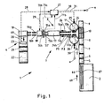
- Fig. 1 schematically shows a plan view of a multi-segment filter manufacturing machine according to the invention 1. This is divided into a group forming device 2, a strand forming device 3 and a discharge device 4.
- the group-forming device 2 may be configured, for example, as in FIG WO 03/024256 A2 or the EP 1 393 640 B1 , wherein preferably the group formation is not single-lane as disclosed in these two documents, but two-lane.
- the filter segment webs are shown schematically at 66 and 67, respectively Fig. 1 shown in the group forming device 2.
- the correspondingly formed filter segment groups are then transferred to a transfer drum 5, which transfers the filter segment groups to a transfer drum 6. From there, in this embodiment, the groups of filter segments are transferred to an accelerator drum 7 and from there to a transfer drum 8, which transfers a web of filter segment groups on a double transfer drum 10, wherein the other web is removed by a take-off drum 9 and then on the double transfer drum 10th is handed over.
- a transfer drum 5 which transfers the filter segment groups to a transfer drum 6.
- the groups of filter segments are transferred to an accelerator drum 7 and from there to a transfer drum 8, which transfers a web of filter segment groups on a double transfer drum 10, where
- the filter segments or filter segment groups are set to in Fig. 1 Not shown wrapping material strips 116, 117 placed, for example, have two glue tracks for holding the filter segments. These glue marks are arranged after the wrapping of the filter segments at about 4 o'clock and 8 o'clock position.
- the glue traces can consist of both hotmelt and PVA.
- Fig. 2 schematically shows the process just described and the organs used for this purpose or a device according to the invention for transferring a stream of cross-axially funded filter segments F1 and F2 or groups 13a, 13b of filter segments F1, F2 in two longitudinally funded strands of filter segments or groups of filter segments.
- the two webs 66 and 67 of filter segment groups 13a and 13b assembled from the group forming device 2 are taken over by a transfer drum 5 and transferred from there to a transfer drum 6.
- the transfer drums 5 and 6 have receiving troughs 62.
- the reference numerals for the filter segment webs 64 and 65 shown there are also shown.
- the rear web 64 is transferred from filter segment groups to a double transfer drum 10.
- a double transfer drum 10 This is schematically in Fig. 3 also indicated, wherein the rear part of the transfer drum 10 accommodates the respective filter segment groups 13b.
- the other web 65 of filter segment groups 13a is transferred via a take-off drum 9 to the front part of the double transfer drum 10.
- the front part and the rear part of the double transfer drum 10 rotate opposite to each other, so that the respective filter segment groups 13a and 13b can be securely transferred to the insert wheels 11 and 12.
- the insert wheels 11 and 12 which are arranged in this example V-shaped, whose axes or axes of rotation 92, 93 to each other thus have an angle of about 70 °, each have Einlegeradabilityarme 41, which also have corresponding wells into which the Filter segment groups 13a and 13b can be inserted accordingly.
- the insert wheels 11 and 12 are rotated at a rotational speed which is slightly greater than the conveying speed of the filter strands 14a and 14b.
- the rotational speeds of the insert wheels are variable.
- FIG. 2 it is a variant of the transfer of filter segment groups or filter segments from the group forming device 2 in filter strands 14a and 14b.
- the correspondingly transferred filter segment groups 13a and 13b, which form a filter strand 14a and 14b have been correspondingly placed on a wrapping material strip, not shown, for example, each of a format strip, the in Fig. 3 is shown schematically, is driven. Subsequently, the filter strands are guided in the conveying direction 24 through a formatting device 17, in which the wrapping material strips are wound around the respective filter strands 14a and 14b and glued. Thus, wrapped filter strands 15a and 15b are formed. These are cut in the cutter 18.
- the cutting device 18 is, for example, a rotating knife.
- multi-segment filters 16a and 16b are cut to length corresponding to the filter strands 15a and 15b.
- the transfer device 19 may be a two-lane so-called spider of the Applicant, which is common in two-lane cigarette rod making machines.
- the multi-segment filters 16a and 16b are arranged transaxially one behind the other on a measuring drum 20, in or on which a sensor device 23 is arranged.
- the measuring device or sensor device 23 generates, inter alia, a measuring signal 28, which is fed to a regulating device 27 becomes.
- the measuring signal 28 may contain, for example, an indication as to how far the position of one or more filter segments deviates from a desired and predeterminable position. From this signal 28 and / or from measurement signals 71a and 71b, which are provided by sensors 70a and 70b, corresponding control signals 30 and 31 are generated, which are supplied to the drives 25 and 26 of the insert wheels 11 and 12. As a result, preferably the speed of insertion of the filter segment groups 13a and 13b can be controlled.
- the control device 27 can generate a control signal 29, which drives the drive of the cutting device 18.
- a lighting device 32 ' is provided, by means of which electromagnetic radiation is radiated in the direction of the two strands 15a and 15b in order to detect correspondingly in the transmitted light method, where the respective position of the filter segments or groups of filter segments in the filter string 15a and 15b, respectively.
- the electromagnetic radiation is visible light, infrared light or ultraviolet light.
- a capacitive measurement can also be carried out if, for example, filter segments have activated charcoal granulate or are acetate filter segments loaded with activated charcoal.
- the sensor devices 70a and 70b may alternatively be provided to the sensor 23 or cumulatively.
- the latter alternately measures multi-segment filters 16a and 16b from the strands 15a and 15b, so that measuring signals are always fed alternately to the respective layers of filter segments or groups of filter segments in the multi-segment filter of the control device 27.
- the control signals 30 and 31, which are supplied to the drives 25 and 26 of the insert wheels 11 and 12, can now be used to change the position of the filter segments or groups of filter segments, for example, to perform a cut as possible simultaneously in both filter strands 15a and 15b and thus transferring the multi-segment filters 16a and 16b to the discharge device 4 in approximately a transverse axial alignment with one another.
- a device may be provided on the discharge device 4 in order to transfer non-aligned multi-segment filters into cross-axially aligned multi-segment filters. For this purpose, for example, find a stop in example of the measuring drum 20 use.
- FIG. 3 schematically a three-dimensional representation of another device according to the invention for transferring a stream of cross-axially funded filter segments or groups of filter segments, which are arranged axially axially behind the other in the transverse axial conveying, shown in two longitudinally axially promoted strands of filter segments or groups of filter segments.
- two webs of filter segment groups 64 and 65 are conveyed from the transfer drum 5 to the transfer drum 6 and another transfer drum 6 '. These two tracks 64 and 65 then arrive in the embodiment of Fig. 3 as in the embodiment according to Fig.
- the filter segments or groups of filter segments of the webs 64 and 65 are removed from a transfer drum 8, and the front web 65 and the filter segment groups of the front web 65 are transferred to the loading wheel 12.
- the filter segments or groups of filter segments of the rear track 64 are still transferred to a take-off drum 9 and from There, the Einlegerad 11.
- Correspondingly cranked guides can be provided for this purpose, so that the receptacles of the Einlegeradabilityarme 41 and 41 'are each arranged parallel to each other on the conveying path.
- Fig. 3 are schematically shown the axes of rotation 92 and 93 of the insert wheels 11 and 12.
- the insertion wheels which may also be referred to as transfer devices, are arranged in a V-shape, can also efficiently serve to longitudinally axially conveyed strands 14a and 14b of rod-shaped articles 13a and 13b into one or two streams cross-axially promoted rod-shaped article to transfer.
- This can in particular also serve to transfer tobacco strands or tobacco sticks from a longitudinal axial conveying direction into a transverse axial conveying direction.
- the tobacco strands should be cut before transferring them into rod-shaped articles, for example tobacco sticks, and then the tobacco sticks themselves are removed from the insertion processes 11 and 12 from the longitudinally conveyed tobacco strands and onto the transfer drums 8 and 9 according to FIG Fig. 3 or on the transfer drum 10 according to Fig. 2 be transferred.
- Fig. 4 shows a further preferred embodiment of the device according to the invention.
- separation of the webs 64 and 65 occurs immediately after the transfer drum 6 performed.
- the accelerator drum 80 has in each case two accelerator drum rings 83 and 83 ', which respectively have a plurality of receiving arms 84 and 85.
- the receiving troughs which are provided for receiving the filter segment groups 13b of the front track 65, perform a circular movement whose diameter is smaller than that of the receptacles which are provided for receiving the filter segment groups 13a of the rear track 64.
- the difference of the radii of these circular paths corresponds to the distance of the filter strands 14a and 14b formed.
- the insert wheels 11 and 12 are provided in this embodiment with a collinear axis of rotation 92 to 93.
- the insert wheel 11, which is provided for the formation of the filter strand 14a, has a larger radius than the insert wheel 12, which is provided for the formation of the filter strand 14b.
- the Einlegeradabilityarme 41 'and the receiving troughs of the Einlegeradabilityarme 41' by a distance closer to the axis of rotation of the accelerator drum 80 is arranged, which corresponds to the distance of the formed filter strands 14a and 14b.
- an efficient transfer of the filter segment groups 13a and 13b can be performed from a single side, wherein the insert wheels 11 and 12 can still be driven independently of each other. This is a particularly clear and easily visible embodiment of the invention.
- Fig. 5a is a further embodiment of the invention in a schematic shown in three-dimensional representation.
- the same design is in Fig. 5b shown schematically in a frontal view.
- the webs 64 and 65 of filter segment groups are respectively transferred from the transfer drums 5 and 6 to an accelerator drum 7.
- the two webs 64 and 65 of filter segment groups 13a and 13b pass onto a transfer drum 90 having two drum rings 88 and 89 whose axes of rotation and their orbital axes 114 and 115 are offset from each other, in particular offset in the direction of the double loading wheel 91
- the desired spacing of the receiving troughs 62 and 63 provided on each double receiving arm 87 is made possible.
- the corresponding receiving trough 60 of the receiving arms 86 of the rear drum ring 88 is also in accordance with Fig. 5b clearly shown.
- the receiving wells 61 of the front drum ring 88 are correspondingly in Fig. 5b well depicted.
- the rear drum ring 88 may comprise receiving arms 86 that are designed to be movable, movable or movable radially outwards, so that when the filter segment groups 13b are transferred from the accelerator drum 7, the receiving recess of the receiving arm 86 provided for this purpose is longitudinally aligned with the adjacent receiving recess of the drum ring 89 is.
- the axes 114 and 115 should be on top of each other.
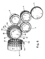
- Fig. 6 shows a further schematic three-dimensional representation of a further inventive embodiment of a device according to the invention, in which from a single side filter segment groups 13a and 13b are provided on a Einlegead 91 with double receiving arms 87.
- this embodiment will be divided the filter segment tracks 64 and 65 after the transfer drum 6 on two pickup drums 9 and 9 'and then passed to the accelerator drum 80, the two accelerator drum rings 83 and 83' has.
- the accelerator drum rings are equipped with receiving arms 84 and 85, the receiving troughs 60 and 61 respectively on an imaginary circular outer shell or circular move, the diameter of the troughs 61 of the generated in the movement of the accelerator drum ring 83 is smaller than that of the troughs 60th the accelerator drum ring 83 '.
- the desired spacing of the filter segment groups 13a and 13b is achieved during the transfer into the receptacles of the double receiving arms 87 of the loading wheel 91.
- Fig. 7 is a schematic three-dimensional representation of a double transfer drum 10 with corresponding drive members.
- the dual transfer drum 10 has a first trough ring 100 and a second trough ring 101 with corresponding troughs 61 and 60, which, as the arrows indicate, are driven in opposite directions.
- the first bowl ring 100 is driven directly by a motor 102, a gear 105, a toothed belt 104 and a gear 106.
- the second trough ring 101 is directly driven by a further motor 103 in opposite directions to the first trough ring 100.
- the axis of rotation or axis of rotation is marked 94.
- Fig. 8 shows a very schematic sectional view of another embodiment of a double transfer drum 10, which in Fig. 2 can also be used, in which, however, only a first motor 102 is used.
- the first motor 102 is connected to a gear 105, which is connected via a toothed belt in engagement with the gear 106 and a ring gear 106. This drives the first well ring 100 directly via the housing.
- the second Trough ring 101 is driven via an inner link gear 113 via a linkage connected to a gear 112, which is mounted in a holder 110 and 111 in the housing.
- F1 filter segment F2 filter segment 1 Multi-segment filter production machine 2 Group-forming device 3 Strand forming device 4 removal device 5 Transfer drum 6, 6 ' Transfer drum 7 accelerating drum 8th Transfer drum 9, 9 ' doffer 10 Double transfer drum 11 insertion wheel 12 insertion wheel 13a, 13b Filter segment group 14a, 14b filter rod 15a, 15b wrapped filter strand 16a, 16b Multi-segment filter 17 format device 18 cutter 19 Transfer device 20 thimble 21 Ausschleustrommel 22 Dispenser 23 sensor device 24 conveying direction 25 drive 26 drive 27 control device 28 measuring signal 29 control signal 30 control signal 31 control signal 32 ' lighting device 40 pickup 41, 41 ' Einlegeradabilityarm 50 - 56 filter segment 60, 61 trough 62, 63 trough 64, 65 Filter segment Bahn 66, 67 Filter segment Bahn 69 transverse axial conveying direction 70a, 70b sensor 71a, 71b measuring signal 80 accelerating drum 81 Einlegeradring 82 Einlegeradring 83
Landscapes
- Cigarettes, Filters, And Manufacturing Of Filters (AREA)
- Manufacturing Of Cigar And Cigarette Tobacco (AREA)
Claims (13)
- Dispositif pour convertir un courant (64, 65) de segments de filtre (F1, F2) ou groupes (13a, 13b) de segments de fltre (F1, F2) de l'industrie de transformation du tabac, transportés transversalement à leur axe et disposés côte à côte dans la direction de leur axe longitudinal lors du transport transversal à leur axe, en deux boudins (14a, 14b, 15a, 15b) de segments de filtre (F1, F2) ou groupes (13a, 13b) de segments de filtre (F1, F2) transportés dans la direction de leur axe longitudinal, caractérisé en ce qu'est prévu pour chaque boudin (14a, 14b, 15a, 15b) un organe d'insertion (11, 12) qui insère les segments de filtre (F1, F2) ou groupes (13a, 13b) de segments de filtre (F1, F2) dans le boudin respectif (14a, 14b, 15a, 15b).
- Dispositif selon la revendication 1, caractérisé en ce que les organes d'insertion (11, 12) sont des roues d'insertion, l'organe d'insertion (11) pour un boudin (14a, 15a) pouvant en particulier être entraîné indépendamment de l'organe d'insertion (12) prévu pour l'autre boudin (14b, 15b), les organes d'insertion (11, 12) étant en particulier aptes à tourner chacun autour d'un axe de rotation (92, 93), les axes de rotation (92, 93) des organes d'insertion (11, 12) étant en particulier disposés en formant entre eux un angle de 20° à 160°, en particulier de 60° à 120°, en particulier de 80° à 100°, ou en ce que les axes de rotation (92, 93) des organes d'insertion (11, 12) sont colinéaires ou parallèles entre eux.
- Dispositif selon la revendication 1 ou 2, caractérisé en ce que le dispositif peut être entraîné ou est entraîné en direction inverse et en ce qu'il sert à ou est utilisé pour convertir deux boudins (14a, 14b, 15a, 15b) de segments de filtre (F1, F2), de groupes (13a, 13b) de segments de filtre (F1, F2) ou de bâtons de tabac, transportés dans la direction de leur axe longitudinal, en un courant de segments de filtre (F1, F2), de groupes (13a, 13b) de segments de filtre (F1, F2) ou de bâtons de tabac transportés transversalement à leur axe, les organes d'insertion (11, 12) étant conçus en tant qu'organes de conversion.
- Dispositif pour convertir un courant (64, 65) de segments de filtre (F1, F2) ou groupes (13a, 13b) de segments de filtre (F1, F2) de l'industrie de transformation du tabac, transportés transversalement à leur axe et disposés côte à côte dans la direction de leur axe longitudinal lors du transport transversal à leur axe, en deux boudins (14a, 14b, 15a, 15b) de segments de filtre (F1, F2) ou groupes (13a, 13b) de segments de filtre (F1, F2) transportés dans la direction de leur axe longitudinal, caractérisé en ce qu'est prévu au moins un organe d'insertion (11, 12, 91) qui insère les segments de filtre (F1, F2) ou groupes (13a, 13b) de segments de filtre (F1, F2) dans deux boudins de filtre (14a, 14b, 15a, 15b), un dispositif de transfert (80, 90) étant prévu pour permettre le transfert des segments de filtre (F1, F2) ou groupes (13a, 13b) de segments de filtre (F1, F2) depuis un seul côté dans l'organe d'insertion (11, 12, 91), au moins au nombre de un, le dispositif de transfert (80, 90) comportant des logements (60, 61) pour deux voies (64, 65) de segments de filtre (F1, F2) ou groupes (13a, 13b) de segments de filtre (F1, F2) à transporter transversalement à leur axe, au moins deux segments de filtre (F1, F2) pouvant être reçus par logement (60, 61), les voies (64, 65) étant formées circonférentiellement par sections, l'une des deux voies (64, 65) présentant, par sections, une trajectoire circulaire plus étroite que l'autre voie.
- Dispositif selon la revendication 4, caractérisé en ce que les deux voies (64, 65) sont formées circonférentiellement par sections, au moins l'un des axes de trajectoire circulaire (114, 115) de l'une des voies étant situé en un point différent de celui de l'autre voie.
- Machine de fabrication de filtres multisegments (16a, 16b) de l'industrie de transformation du tabac, équipée d'un dispositif (3) selon l'une des revendications 1 à 5.
- Machine selon la revendication 6, caractérisée en ce qu'est prévu un dispositif d'assemblage de segments de filtre (2) situé en amont du dispositif (3) selon l'une des revendications 1 à 5, dans laquelle, en particulier, le dispositif d'assemblage de segments de filtre (2) rassemble et transporte deux voies (66, 67) de groupes (13a, 13b) de segments de filtre (F1, F2) transportés transversalement à leur axe, un groupe (13a) de segments de filtre (F1, F2) d'une voie (66) étant en particulier respectivement disposé suivant l'axe longitudinal derrière un groupe (13b) de segments de filtre (F1, F2) de l'autre voie (67).
- Procédé pour convertir un courant (64, 65) de segments de filtre (F1, F2) ou groupes (13a, 13b) de segments de filtre (F1, F2) de l'industrie de transformation du tabac, transportés transversalement à leur axe, en deux boudins (14a, 14b, 15a, 15b) de segments de filtre (F1, F2) ou groupes (13a, 13b) de segments de filtre (F1, F2) transportés dans la direction de leur axe longitudinal, comprenant les étapes suivantes :- transport d'un courant (64, 65) de segments de filtre (F1, F2) ou groupes (13a, 13b) de segments de filtre (F1, F2) dans une direction orientée transversalement à l'axe longitudinal des segments de filtres (F1, F2) ou des groupes (13a, 13b) de segments de filtre (F1, F2), les segments de filtres (F1, F2) ou groupes (13a, 13b) de segments de filtre (F1, F2) étant disposés côte à côte dans la direction de leur axe longitudinal lors du transport transversal à leur axe,- conversion du courant (64, 65) de segments de filtres (F1, F2) ou groupes (13a, 13b) de segments de filtre (F1, F2) en un premier (64) et un second (65) courants partiels de segments de filtres (F1, F2) ou de groupes (13a, 13b) de segments de filtre (F1, F2),- passage du premier courant partiel (64) sur un premier organe d'insertion (11, 12) et du second courant partiel (65) sur un second organe d'insertion (12, 11), et- insertion des segments de filtres (F1, F2) ou groupes (13a, 13b) de segments de filtre (F1, F2) du premier courant partiel (64) dans un premier organe de transport (116) transporté suivant l'axe longitudinal, permettant ainsi la formation d'un premier boudin (14a) transporté dans la direction de son axe longitudinal, et insertion des segments de filtres (F1) ou groupes (13a, 13b) de segments de filtre (F1, F2) du second courant partiel (65) dans un second organe de transport (117) transporté suivant l'axe longitudinal, permettant ainsi la formation d'un second boudin (14b) transporté dans la direction de son axe longitudinal.
- Procédé selon la revendication 8, caractérisé en ce que l'insertion des segments de filtre (F1, F2) ou groupes (13a, 13b) de segments de filtre (F1, F2) du premier courant partiel (64) s'effectue indépendamment de l'insertion des segments de filtre (F1, F2) ou groupes (13a, 13b) de segments de filtre (F1, F2) du second courant partiel (65), deux organes d'insertion (11, 12) entraînés indépendamment l'un de l'autre étant en particulier prévus pour l'insertion, en particulier, le premier courant partiel (64) et le second courant partiel (65) étant transportés par intermittence en sens inverse l'un de l'autre, en particulier sur un organe de transport (10).
- Procédé pour convertir un courant (64, 65) de groupes (13a, 13b) de segments de filtre (F1, F2) de l'industrie de transformation du tabac, transportés transversalement à leur axe, en deux boudins (14a, 14b, 15a, 15b) de groupes (13a, 13b) de segments de filtre (F1, F2) transportés dans la direction de leur axe longitudinal, comprenant les étapes suivantes :- transport d'un courant (64, 65) de groupes (13a, 13b) de segments de filtre (F1, F2) dans une direction orientée transversalement à l'axe longitudinal des groupes (13a, 13b) de segments de filtre (F1, F2), les groupes (13a, 13b) de segments de filtre (F1, F2) étant disposés côte à côte dans la direction de leur axe longitudinal lors du transport transversal à leur axe,- conversion du courant (64, 65) de groupes (13a, 13b) de segments de filtre (F1, F2) en un premier (64) et un second (65) courants partiels de groupes (13a, 13b) de segments de filtre (F1, F2),- transfert du premier et du second courants partiels de groupes (13a, 13b) de segments de filtre (F1, F2) depuis un seul côté dans au moins un organe d'insertion (11, 12, 91), et- insertion des groupes (13a, 13b) de segments de filtre (F1, F2) du premier courant partiel (64) dans un premier organe de transport (116) transporté suivant l'axe longitudinal, permettant ainsi la formation d'un premier boudin (14a) transporté dans la direction de son axe longitudinal, et insertion des groupes (13a, 13b) de segments de filtre (F1, F2) du second courant partiel (65) dans un second organe de transport (117) transporté suivant l'axe longitudinal, permettant ainsi la formation d'un second boudin (14b) transporté dans la direction de son axe longitudinal.
- Procédé selon l'une des revendications 8 à 10, caractérisé en ce que la conversion du courant en un premier et un second courants partiels (64, 65) s'effectue dans un dispositif d'assemblage de segments de filtre (2), le transfert du courant dans un premier et second courant partiel (64, 65) ayant lieu en particulier avant un assemblage complet de groupes (13a, 13b) de segments de filtres (F1, F2).
- Procédé pour convertir deux boudins (14a, 14b, 15a, 15b) d'articles en forme de tige (F1, F2, 13a, 13b) de l'industrie de transformation du tabac transportés dans la direction de leur axe longitudinal en un courant (64, 65) d'articles en forme de tige (F1, F2, 13a, 13b) de l'industrie de transformation du tabac, comprenant les étapes suivantes :- transport des articles en forme de tige (F1, F2, 13a, 13b) dans la direction de leur axe longitudinal dans un premier boudin (14a, 15a) et dans un second boudin (14b, 15b),- passage des articles en forme de tige (F1, F2, 13a, 13b) du premier boudin (14a, 14b) dans un premier organe d'insertion (11, 12) et passage des articles en forme de tige (F1, F2, 13a, 13b) du second boudin (14b, 15b) dans un second organe d'insertion (11, 12), les organes d'insertion (11, 12) convertissant le transport des articles en forme de tige (F1, F2, 13a, 13b) dans la direction de leur axe longitudinal en un transport des articles en forme de tige (F1, F2, 13a, 13b) transversalement à leur axe,- transfert des articles en forme de tige (F1, F2, 13a, 13b) dans au moins un organe de transport (8, 9, 10), les articles en forme de tige (F1, F2, 13a, 13b) étant transportés dans l'organe de transport, au moins au nombre de un, transversalement à leur axe, deux courants partiels (64-67) d'articles en forme de tige (F1, F2, 13a, 13b) étant formés lors du transfert, lesquels sont transportés transversalement à leur axe, le transfert des articles en forme de tige (F1, F2, 13a, 13b) du premier boudin (14a, 15a) dans le premier organe d'insertion (11, 12) et le transfert subséquent dans l'organe de transport (8-10), au moins au nombre de un, étant indépendants du transfert des articles en forme de tige (F1, F2, 13a, 13b) du second boudin (14b, 15b) dans le second organe d'insertion (11, 12) et du transfert subséquent dans l'organe de transport (8-10), au moins au nombre de un.
- Procédé selon la revendication 12, caractérisé en ce que les deux organes d'insertion (11, 12) sont entraînés indépendamment l'un de l'autre, en particulier les organes d'insertion (11, 12) pivotent chacun autour d'un axe de rotation (92, 93), les axes de rotation (92, 93) des organes d'insertion (11, 12) n'étant pas parallèles entre eux, en particulier les axes de rotation (92, 93) des organes d'insertion (11, 12) formant entre eux un angle de 20° à 160°, en particulier de 60° à 120°, en particulier de 80° à 100°.
Priority Applications (2)
| Application Number | Priority Date | Filing Date | Title |
|---|---|---|---|
| PL10175229T PL2294934T3 (pl) | 2009-09-15 | 2010-09-03 | Wkładanie segmentów filtrowych do pasm filtrowych |
| EP13167437.6A EP2628399B2 (fr) | 2009-09-15 | 2010-09-03 | Tambour de transfert de l'industrie de traitement du tabac |
Applications Claiming Priority (1)
| Application Number | Priority Date | Filing Date | Title |
|---|---|---|---|
| DE102009041318A DE102009041318A1 (de) | 2009-09-15 | 2009-09-15 | Einlegen von Filtersegmenten in Filterstränge |
Related Child Applications (2)
| Application Number | Title | Priority Date | Filing Date |
|---|---|---|---|
| EP13167437.6A Division EP2628399B2 (fr) | 2009-09-15 | 2010-09-03 | Tambour de transfert de l'industrie de traitement du tabac |
| EP13167437.6 Division-Into | 2013-05-13 |
Publications (3)
| Publication Number | Publication Date |
|---|---|
| EP2294934A2 EP2294934A2 (fr) | 2011-03-16 |
| EP2294934A3 EP2294934A3 (fr) | 2011-03-23 |
| EP2294934B1 true EP2294934B1 (fr) | 2013-08-07 |
Family
ID=43301841
Family Applications (2)
| Application Number | Title | Priority Date | Filing Date |
|---|---|---|---|
| EP10175229.3A Not-in-force EP2294934B1 (fr) | 2009-09-15 | 2010-09-03 | Insertion de segments de filtre dans des boudins de filtre |
| EP13167437.6A Active EP2628399B2 (fr) | 2009-09-15 | 2010-09-03 | Tambour de transfert de l'industrie de traitement du tabac |
Family Applications After (1)
| Application Number | Title | Priority Date | Filing Date |
|---|---|---|---|
| EP13167437.6A Active EP2628399B2 (fr) | 2009-09-15 | 2010-09-03 | Tambour de transfert de l'industrie de traitement du tabac |
Country Status (5)
| Country | Link |
|---|---|
| EP (2) | EP2294934B1 (fr) |
| JP (1) | JP2011062198A (fr) |
| CN (3) | CN104824843B (fr) |
| DE (1) | DE102009041318A1 (fr) |
| PL (1) | PL2294934T3 (fr) |
Families Citing this family (20)
| Publication number | Priority date | Publication date | Assignee | Title |
|---|---|---|---|---|
| DE102009054801A1 (de) | 2009-12-16 | 2011-06-22 | HAUNI Maschinenbau Aktiengesellschaft, 21033 | Multisegmentfilterherstellung der Tabak verarbeitenden Industrie |
| IT1400727B1 (it) | 2010-07-08 | 2013-07-02 | Gd Spa | Macchina e metodo per la produzione di filtri composti. |
| ITBO20110158A1 (it) * | 2011-03-28 | 2012-09-29 | Gd Spa | Tamburo di trasferimento o di accompagnamento per spezzoni di filtro o di sigaretta con teste operative portate da bracci radiali. |
| DE102011007430B4 (de) | 2011-04-14 | 2013-02-07 | Hauni Maschinenbau Ag | Förderung von stabförmigen Artikeln der Tabak verarbeitenden Industrie |
| EP2813152B8 (fr) | 2011-06-03 | 2020-04-01 | Tobacco Research And Development Institute (Proprietary) Limited | Assembleuse cigarettes-filtres pour d'articles à fumer avec deux papiers de manchette |
| DE102011085534B4 (de) * | 2011-11-01 | 2013-07-04 | Hauni Maschinenbau Ag | Verfahren und Vorrichtung zum Vereinzeln und Einlegen von Objekten in einen Materialstrang der Tabak verarbeitenden Industrie |
| DE102012201922B3 (de) * | 2012-02-09 | 2013-08-01 | Hauni Maschinenbau Ag | Fördereinrichtung zum Fördern stabförmiger Produkte der Tabak verarbeitenden Industrie und Verfahren zur Steuerung einer derartigen Fördervorrichtung |
| DE102012206344B3 (de) * | 2012-04-18 | 2013-07-11 | Hauni Maschinenbau Ag | Einrichtung zur Zusammenstellung von Filtersegmentgruppen |
| DE102012207346A1 (de) | 2012-05-03 | 2013-11-07 | Hauni Maschinenbau Ag | Verfahren und Einrichtung zum Zusammenstellen von Filtersegmentgruppen |
| DE102012213338B4 (de) * | 2012-07-30 | 2014-10-09 | Hauni Maschinenbau Ag | Verfahren und Vorrichtung zum Herstellen von Multisegmentfilterstäben der Tabak verarbeitenden Industrie |
| PL2928327T3 (pl) | 2012-12-06 | 2019-12-31 | British American Tobacco (Investments) Ltd | Ulepszenia dotyczące montażu wyrobu do palenia |
| DE102013221115A1 (de) * | 2013-10-17 | 2015-04-23 | Hauni Maschinenbau Ag | Schneiden von stabförmigen Artikeln der Tabak verarbeitenden Industrie |
| DE102015106347A1 (de) * | 2015-04-24 | 2016-10-27 | Hauni Maschinenbau Gmbh | Strangmaschine der Tabak verarbeitenden Industrie und Verfahren zum Herstellen von Multisegmentstäben |
| ITUB20154735A1 (it) | 2015-10-19 | 2017-04-19 | Gd Spa | Dispositivo saldatore e metodo per la sua realizzazione. |
| DE102016109740A1 (de) * | 2016-05-26 | 2017-11-30 | Hauni Maschinenbau Gmbh | Einlegevorrichtung und Strangmaschine der Tabak verarbeitenden Industrie |
| DE102017106133A1 (de) * | 2017-03-22 | 2018-09-27 | Hauni Maschinenbau Gmbh | Verfahren zum Steuern eines Strangabschneiders und Strangmaschine der Tabak verarbeitenden Industrie |
| IT201800006412A1 (it) * | 2018-06-18 | 2019-12-18 | Unità e metodo di rilevazione per l’industria del tabacco | |
| CN108750559A (zh) * | 2018-07-23 | 2018-11-06 | 新乡东方工业科技有限公司 | 一种滤棒齿盘传输机构 |
| CN108783585A (zh) * | 2018-07-30 | 2018-11-13 | 熊婧 | 一种加热不燃烧卷烟制造中同步供给短烟支的方法 |
| EP3909438B1 (fr) * | 2020-05-12 | 2024-04-10 | G.D S.p.A. | Unité de transfert |
Family Cites Families (29)
| Publication number | Priority date | Publication date | Assignee | Title |
|---|---|---|---|---|
| GB994813A (en) * | 1962-09-19 | 1965-06-10 | Kurt Koerber | Apparatus for varying the feed path of rod-like articles moved transversely to theiraxes |
| US3270601A (en) * | 1963-11-14 | 1966-09-06 | Hauni Werke Koerber & Co Kg | Apparatus for manipulating rod-like material |
| GB1149312A (en) * | 1967-02-15 | 1969-04-23 | Desmond Walter Molins | Improvements in or relating to the tip-turning of cigarettes |
| DE2064536C2 (de) * | 1970-12-30 | 1982-06-24 | Hauni-Werke Körber & Co KG, 2050 Hamburg | Vorrichtung zum fortlaufendem Umhüllen eines Filtermaterials der tabakverarbeitenden Industrie mit einem Umhüllungsstreifen |
| DE2256420A1 (de) * | 1972-11-17 | 1974-05-30 | Hauni Werke Koerber & Co Kg | Ablegeanordnung fuer mit mundstuecken versehene stabfoermige rauchartikel herstellende maschinen |
| IT1189249B (it) * | 1982-03-29 | 1988-01-28 | Gd Spa | Dispositivo di traslazione assiale di spezzoni di sigaretta |
| JPS59113880A (ja) * | 1982-12-22 | 1984-06-30 | 日本たばこ産業株式会社 | 巻たばこ反転装置 |
| IT1181265B (it) * | 1984-12-06 | 1987-09-23 | Gd Spa | Dispositivo per il trasferimento di articoli a forma di barretta |
| IT1238237B (it) * | 1990-02-08 | 1993-07-12 | Gd Spa | Metodo per la realizzazione di sigarette col filtro. |
| IT1294164B1 (it) * | 1997-08-08 | 1999-03-22 | Gd Spa | Metodo e dispositivo per trasferire degli articoli. |
| DE19751598B4 (de) * | 1997-11-21 | 2008-04-17 | Hauni Maschinenbau Ag | Verfahren und Vorrichtung zum Behandeln eines Filtertowstreifens |
| CN2397745Y (zh) * | 1999-12-03 | 2000-09-27 | 叶凯 | 烟支锥轮调头机构 |
| DE10141703A1 (de) * | 2001-08-25 | 2003-03-06 | Hauni Maschinenbau Ag | Übertragungsvorrichtung und Verfahren zum Übertragen von Artikeln der tabakverarbeitenden Industrie |
| DE10146019A1 (de) * | 2001-09-18 | 2003-04-03 | Hauni Maschinenbau Ag | Einrichtung zum Zusammenstellen von Gruppen von Filtersegmenten zur Herstellung von Multisegmentfiltern der tabakverarbeitenden Industrie und Muldentrommel |
| DE10146992A1 (de) * | 2001-09-18 | 2003-04-03 | Hauni Maschinenbau Ag | Übergabeeinrichtung und Muldentrommel sowie Verfahren zur Übergabe von Hartfilterlementen |
| DE10163761A1 (de) * | 2001-12-27 | 2003-07-17 | Hauni Maschinenbau Ag | Einrichtung und System zum Messen von Eigenschaften von Multisegmentfiltern sowie Verfahren hierzu |
| EP1393640B1 (fr) | 2002-09-02 | 2006-12-06 | Hauni Maschinenbau AG | Méthode et appareil pour composer des groupes de segments de filtre |
| ES2264459T3 (es) * | 2002-09-11 | 2007-01-01 | Hauni Maschinenbau Ag | Procedimiento y dispositivo para medir la longitud y el diametro de barras de filtro. |
| ITBO20030641A1 (it) * | 2003-10-31 | 2005-05-01 | Gd Spa | Dispositivo di alimentazione di bacchette di filtro in |
| DE10354924B4 (de) * | 2003-11-25 | 2024-01-18 | Körber Technologies Gmbh | Vorrichtung zum Aufbereiten von Filtertowmaterial sowie Vorrichtung zur Herstellung von Filtern |
| WO2006004111A1 (fr) | 2004-07-07 | 2006-01-12 | Japan Tobacco Inc. | Machine pour la fabrication de filtres |
| DE102004047266A1 (de) | 2004-09-24 | 2006-04-06 | Hauni Maschinenbau Ag | Vorrichtung zur Übergabe stabförmiger Artikel |
| DE102004057091B3 (de) * | 2004-11-25 | 2006-06-14 | Hauni Maschinenbau Ag | Einstoßtrommel |
| ITBO20050184A1 (it) * | 2005-03-24 | 2005-06-23 | Gd Spa | Apparecchiatura di produzione di filtri composti |
| ITBO20050696A1 (it) * | 2005-11-16 | 2007-05-17 | Gd Spa | Macchina per la produzione di filtri composti |
| DE102006042238A1 (de) * | 2006-09-06 | 2008-03-27 | Hauni Maschinenbau Ag | Einrichtung zum Fördern von stabförmigen Artikeln |
| ITBO20060720A1 (it) | 2006-10-18 | 2008-04-19 | Gd Spa | Macchina per la produzione di filtri composti. |
| ITBO20060719A1 (it) | 2006-10-18 | 2008-04-19 | Gd Spa | Macchina per la produzione di filtri composti. |
| ITBO20060718A1 (it) * | 2006-10-18 | 2008-04-19 | Gd Spa | Macchina per la produzione di filtri composti |
-
2009
- 2009-09-15 DE DE102009041318A patent/DE102009041318A1/de not_active Ceased
-
2010
- 2010-09-03 EP EP10175229.3A patent/EP2294934B1/fr not_active Not-in-force
- 2010-09-03 PL PL10175229T patent/PL2294934T3/pl unknown
- 2010-09-03 EP EP13167437.6A patent/EP2628399B2/fr active Active
- 2010-09-14 JP JP2010205056A patent/JP2011062198A/ja not_active Withdrawn
- 2010-09-15 CN CN201510131268.3A patent/CN104824843B/zh not_active Expired - Fee Related
- 2010-09-15 CN CN201510131266.4A patent/CN104824842B/zh not_active Expired - Fee Related
- 2010-09-15 CN CN201010293515.7A patent/CN102018285B/zh not_active Expired - Fee Related
Also Published As
| Publication number | Publication date |
|---|---|
| EP2628399B2 (fr) | 2021-04-28 |
| JP2011062198A (ja) | 2011-03-31 |
| CN104824843A (zh) | 2015-08-12 |
| PL2294934T3 (pl) | 2014-01-31 |
| DE102009041318A1 (de) | 2011-03-31 |
| CN104824843B (zh) | 2019-03-01 |
| CN104824842A (zh) | 2015-08-12 |
| CN102018285B (zh) | 2015-06-17 |
| EP2294934A2 (fr) | 2011-03-16 |
| EP2628399A1 (fr) | 2013-08-21 |
| CN102018285A (zh) | 2011-04-20 |
| CN104824842B (zh) | 2020-11-10 |
| EP2628399B1 (fr) | 2014-12-24 |
| EP2294934A3 (fr) | 2011-03-23 |
Similar Documents
| Publication | Publication Date | Title |
|---|---|---|
| EP2628399B1 (fr) | Tambour de transfert de l'industrie de traitement du tabac | |
| EP2335503B1 (fr) | Fabrication d'un filtre multi-segments de l'industrie de traitement du tabac | |
| EP2477513A1 (fr) | Machine et procédé de production de filtres multisegments destinés à l'inductrie du tabac | |
| DE69307962T2 (de) | Verfahren zur Herstellung von Filterzigaretten | |
| US3368460A (en) | Method and apparatus for the production of mouthpieces | |
| EP2684472B1 (fr) | Procédé de commande d'une combinaison de machines et/ou d'une machine pour le traitement d'articles en forme de tige de l'industrie de traitement du tabac et dispositif de machine correspondant | |
| DE1296065B (de) | Vorrichtung zum Herstellen eines zusammengesetzten Stranges aus Bestandteilen fuer Zigaretten od. dgl. | |
| EP2661971B1 (fr) | Fabrication de cigarettes à filtre | |
| EP2363029A1 (fr) | Tambour de transport de l'industrie de traitement du tabac | |
| EP1441604B1 (fr) | Systeme de fabrication de filtres a plusieurs segments avec dispositif destine a envelopper des groupes de segments de filtre avec un materiau d'enveloppage pour la fabrication de filtres a plusieurs segments de l'industrie du tabac | |
| EP1638419A1 (fr) | Machine d'assemblage de filtres a courroie double, et procede de production de cigarettes a bout filtre | |
| EP3641572B1 (fr) | Fabrication de produits à fumer | |
| EP1510142B1 (fr) | Manipulation d'articles en forme de tige de l'industrie du tabac | |
| DE102009041319A1 (de) | Maschine zur Herstellung und Verfahren zum Herstellen von Multisegmentfiltern der Tabak verarbeitenden Industrie | |
| EP1493341B1 (fr) | Assembleuse cigarettes-filtres à double ligne | |
| DE102012103323B4 (de) | Vorrichtung zur Übergabe stabförmiger Artikel der Tabak verarbeitenden Industrie von einer Vorrichtung zur queraxialen Förderung auf eine Vorrichtung zur längsaxialen Förderung oder umgekehrt sowie Anordnung mit einer solchen Vorrichtung | |
| EP1827143B1 (fr) | Tambour poussoir | |
| DE2811176A1 (de) | Verfahren und vorrichtung zum herstellen eines aus unterschiedlichen filterkomponenten zusammengesetzten rezessfilterstranges | |
| DE102016125001A1 (de) | Rotationsfördervorrichtung zum Fördern von Artikeln der tabakverarbeitenden Industrie | |
| EP2692251A1 (fr) | Dispositif et procédé de fabrication de tiges de filtre multi-segments de l'industrie de traitement du tabac | |
| DE2256420A1 (de) | Ablegeanordnung fuer mit mundstuecken versehene stabfoermige rauchartikel herstellende maschinen | |
| EP3378338B1 (fr) | Procédé de commande d'un dispositif de coupe de boudin et machine à boudin de l'industrie de traitement du tabac | |
| DE102004062421B3 (de) | Verfahren zum Transportieren von stabförmigen Artikeln der Tabak verarbeitenden Industrie mit Rollfördereinrichtung | |
| DE102022125966A1 (de) | Verpackung von stabförmigen Produkten der Tabak verarbeitenden Industrie | |
| EP4210515A1 (fr) | Dispositif de transfert de l'industrie du tabac |
Legal Events
| Date | Code | Title | Description |
|---|---|---|---|
| PUAI | Public reference made under article 153(3) epc to a published international application that has entered the european phase |
Free format text: ORIGINAL CODE: 0009012 |
|
| PUAL | Search report despatched |
Free format text: ORIGINAL CODE: 0009013 |
|
| AK | Designated contracting states |
Kind code of ref document: A2 Designated state(s): AL AT BE BG CH CY CZ DE DK EE ES FI FR GB GR HR HU IE IS IT LI LT LU LV MC MK MT NL NO PL PT RO SE SI SK SM TR |
|
| AX | Request for extension of the european patent |
Extension state: BA ME RS |
|
| AK | Designated contracting states |
Kind code of ref document: A3 Designated state(s): AL AT BE BG CH CY CZ DE DK EE ES FI FR GB GR HR HU IE IS IT LI LT LU LV MC MK MT NL NO PL PT RO SE SI SK SM TR |
|
| AX | Request for extension of the european patent |
Extension state: BA ME RS |
|
| 17P | Request for examination filed |
Effective date: 20110915 |
|
| GRAP | Despatch of communication of intention to grant a patent |
Free format text: ORIGINAL CODE: EPIDOSNIGR1 |
|
| GRAS | Grant fee paid |
Free format text: ORIGINAL CODE: EPIDOSNIGR3 |
|
| GRAA | (expected) grant |
Free format text: ORIGINAL CODE: 0009210 |
|
| AK | Designated contracting states |
Kind code of ref document: B1 Designated state(s): AL AT BE BG CH CY CZ DE DK EE ES FI FR GB GR HR HU IE IS IT LI LT LU LV MC MK MT NL NO PL PT RO SE SI SK SM TR |
|
| REG | Reference to a national code |
Ref country code: GB Ref legal event code: FG4D Free format text: NOT ENGLISH |
|
| REG | Reference to a national code |
Ref country code: CH Ref legal event code: EP Ref country code: AT Ref legal event code: REF Ref document number: 625314 Country of ref document: AT Kind code of ref document: T Effective date: 20130815 |
|
| REG | Reference to a national code |
Ref country code: IE Ref legal event code: FG4D Free format text: LANGUAGE OF EP DOCUMENT: GERMAN |
|
| REG | Reference to a national code |
Ref country code: DE Ref legal event code: R096 Ref document number: 502010004270 Country of ref document: DE Effective date: 20131002 |
|
| REG | Reference to a national code |
Ref country code: NL Ref legal event code: T3 |
|
| REG | Reference to a national code |
Ref country code: LT Ref legal event code: MG4D |
|
| PG25 | Lapsed in a contracting state [announced via postgrant information from national office to epo] |
Ref country code: PT Free format text: LAPSE BECAUSE OF FAILURE TO SUBMIT A TRANSLATION OF THE DESCRIPTION OR TO PAY THE FEE WITHIN THE PRESCRIBED TIME-LIMIT Effective date: 20131209 Ref country code: NO Free format text: LAPSE BECAUSE OF FAILURE TO SUBMIT A TRANSLATION OF THE DESCRIPTION OR TO PAY THE FEE WITHIN THE PRESCRIBED TIME-LIMIT Effective date: 20131107 Ref country code: SE Free format text: LAPSE BECAUSE OF FAILURE TO SUBMIT A TRANSLATION OF THE DESCRIPTION OR TO PAY THE FEE WITHIN THE PRESCRIBED TIME-LIMIT Effective date: 20130807 Ref country code: IS Free format text: LAPSE BECAUSE OF FAILURE TO SUBMIT A TRANSLATION OF THE DESCRIPTION OR TO PAY THE FEE WITHIN THE PRESCRIBED TIME-LIMIT Effective date: 20131207 Ref country code: HR Free format text: LAPSE BECAUSE OF FAILURE TO SUBMIT A TRANSLATION OF THE DESCRIPTION OR TO PAY THE FEE WITHIN THE PRESCRIBED TIME-LIMIT Effective date: 20130807 Ref country code: CY Free format text: LAPSE BECAUSE OF FAILURE TO SUBMIT A TRANSLATION OF THE DESCRIPTION OR TO PAY THE FEE WITHIN THE PRESCRIBED TIME-LIMIT Effective date: 20130710 Ref country code: LT Free format text: LAPSE BECAUSE OF FAILURE TO SUBMIT A TRANSLATION OF THE DESCRIPTION OR TO PAY THE FEE WITHIN THE PRESCRIBED TIME-LIMIT Effective date: 20130807 |
|
| REG | Reference to a national code |
Ref country code: PL Ref legal event code: T3 |
|
| PG25 | Lapsed in a contracting state [announced via postgrant information from national office to epo] |
Ref country code: LV Free format text: LAPSE BECAUSE OF FAILURE TO SUBMIT A TRANSLATION OF THE DESCRIPTION OR TO PAY THE FEE WITHIN THE PRESCRIBED TIME-LIMIT Effective date: 20130807 Ref country code: FI Free format text: LAPSE BECAUSE OF FAILURE TO SUBMIT A TRANSLATION OF THE DESCRIPTION OR TO PAY THE FEE WITHIN THE PRESCRIBED TIME-LIMIT Effective date: 20130807 Ref country code: GR Free format text: LAPSE BECAUSE OF FAILURE TO SUBMIT A TRANSLATION OF THE DESCRIPTION OR TO PAY THE FEE WITHIN THE PRESCRIBED TIME-LIMIT Effective date: 20131108 Ref country code: SI Free format text: LAPSE BECAUSE OF FAILURE TO SUBMIT A TRANSLATION OF THE DESCRIPTION OR TO PAY THE FEE WITHIN THE PRESCRIBED TIME-LIMIT Effective date: 20130807 |
|
| BERE | Be: lapsed |
Owner name: HAUNI MASCHINENBAU A.G. Effective date: 20130930 |
|
| PG25 | Lapsed in a contracting state [announced via postgrant information from national office to epo] |
Ref country code: CY Free format text: LAPSE BECAUSE OF FAILURE TO SUBMIT A TRANSLATION OF THE DESCRIPTION OR TO PAY THE FEE WITHIN THE PRESCRIBED TIME-LIMIT Effective date: 20130807 |
|
| PG25 | Lapsed in a contracting state [announced via postgrant information from national office to epo] |
Ref country code: SK Free format text: LAPSE BECAUSE OF FAILURE TO SUBMIT A TRANSLATION OF THE DESCRIPTION OR TO PAY THE FEE WITHIN THE PRESCRIBED TIME-LIMIT Effective date: 20130807 Ref country code: CZ Free format text: LAPSE BECAUSE OF FAILURE TO SUBMIT A TRANSLATION OF THE DESCRIPTION OR TO PAY THE FEE WITHIN THE PRESCRIBED TIME-LIMIT Effective date: 20130807 Ref country code: RO Free format text: LAPSE BECAUSE OF FAILURE TO SUBMIT A TRANSLATION OF THE DESCRIPTION OR TO PAY THE FEE WITHIN THE PRESCRIBED TIME-LIMIT Effective date: 20130807 Ref country code: EE Free format text: LAPSE BECAUSE OF FAILURE TO SUBMIT A TRANSLATION OF THE DESCRIPTION OR TO PAY THE FEE WITHIN THE PRESCRIBED TIME-LIMIT Effective date: 20130807 Ref country code: DK Free format text: LAPSE BECAUSE OF FAILURE TO SUBMIT A TRANSLATION OF THE DESCRIPTION OR TO PAY THE FEE WITHIN THE PRESCRIBED TIME-LIMIT Effective date: 20130807 |
|
| PG25 | Lapsed in a contracting state [announced via postgrant information from national office to epo] |
Ref country code: ES Free format text: LAPSE BECAUSE OF FAILURE TO SUBMIT A TRANSLATION OF THE DESCRIPTION OR TO PAY THE FEE WITHIN THE PRESCRIBED TIME-LIMIT Effective date: 20130807 Ref country code: MC Free format text: LAPSE BECAUSE OF FAILURE TO SUBMIT A TRANSLATION OF THE DESCRIPTION OR TO PAY THE FEE WITHIN THE PRESCRIBED TIME-LIMIT Effective date: 20130807 |
|
| PLBE | No opposition filed within time limit |
Free format text: ORIGINAL CODE: 0009261 |
|
| STAA | Information on the status of an ep patent application or granted ep patent |
Free format text: STATUS: NO OPPOSITION FILED WITHIN TIME LIMIT |
|
| REG | Reference to a national code |
Ref country code: FR Ref legal event code: ST Effective date: 20140530 |
|
| REG | Reference to a national code |
Ref country code: IE Ref legal event code: MM4A |
|
| 26N | No opposition filed |
Effective date: 20140508 |
|
| PG25 | Lapsed in a contracting state [announced via postgrant information from national office to epo] |
Ref country code: BE Free format text: LAPSE BECAUSE OF NON-PAYMENT OF DUE FEES Effective date: 20130930 Ref country code: IE Free format text: LAPSE BECAUSE OF NON-PAYMENT OF DUE FEES Effective date: 20130903 |
|
| REG | Reference to a national code |
Ref country code: DE Ref legal event code: R097 Ref document number: 502010004270 Country of ref document: DE Effective date: 20140508 |
|
| PG25 | Lapsed in a contracting state [announced via postgrant information from national office to epo] |
Ref country code: FR Free format text: LAPSE BECAUSE OF NON-PAYMENT OF DUE FEES Effective date: 20131007 |
|
| PGFP | Annual fee paid to national office [announced via postgrant information from national office to epo] |
Ref country code: PL Payment date: 20140825 Year of fee payment: 5 |
|
| PGFP | Annual fee paid to national office [announced via postgrant information from national office to epo] |
Ref country code: NL Payment date: 20140921 Year of fee payment: 5 |
|
| REG | Reference to a national code |
Ref country code: CH Ref legal event code: PL |
|
| GBPC | Gb: european patent ceased through non-payment of renewal fee |
Effective date: 20140903 |
|
| PG25 | Lapsed in a contracting state [announced via postgrant information from national office to epo] |
Ref country code: SM Free format text: LAPSE BECAUSE OF FAILURE TO SUBMIT A TRANSLATION OF THE DESCRIPTION OR TO PAY THE FEE WITHIN THE PRESCRIBED TIME-LIMIT Effective date: 20130807 |
|
| PG25 | Lapsed in a contracting state [announced via postgrant information from national office to epo] |
Ref country code: MT Free format text: LAPSE BECAUSE OF FAILURE TO SUBMIT A TRANSLATION OF THE DESCRIPTION OR TO PAY THE FEE WITHIN THE PRESCRIBED TIME-LIMIT Effective date: 20130807 Ref country code: TR Free format text: LAPSE BECAUSE OF FAILURE TO SUBMIT A TRANSLATION OF THE DESCRIPTION OR TO PAY THE FEE WITHIN THE PRESCRIBED TIME-LIMIT Effective date: 20130807 |
|
| PG25 | Lapsed in a contracting state [announced via postgrant information from national office to epo] |
Ref country code: CH Free format text: LAPSE BECAUSE OF NON-PAYMENT OF DUE FEES Effective date: 20140930 Ref country code: LI Free format text: LAPSE BECAUSE OF NON-PAYMENT OF DUE FEES Effective date: 20140930 Ref country code: LU Free format text: LAPSE BECAUSE OF NON-PAYMENT OF DUE FEES Effective date: 20130903 Ref country code: GB Free format text: LAPSE BECAUSE OF NON-PAYMENT OF DUE FEES Effective date: 20140903 Ref country code: MK Free format text: LAPSE BECAUSE OF FAILURE TO SUBMIT A TRANSLATION OF THE DESCRIPTION OR TO PAY THE FEE WITHIN THE PRESCRIBED TIME-LIMIT Effective date: 20130807 Ref country code: HU Free format text: LAPSE BECAUSE OF FAILURE TO SUBMIT A TRANSLATION OF THE DESCRIPTION OR TO PAY THE FEE WITHIN THE PRESCRIBED TIME-LIMIT; INVALID AB INITIO Effective date: 20100903 Ref country code: BG Free format text: LAPSE BECAUSE OF FAILURE TO SUBMIT A TRANSLATION OF THE DESCRIPTION OR TO PAY THE FEE WITHIN THE PRESCRIBED TIME-LIMIT Effective date: 20130807 |
|
| REG | Reference to a national code |
Ref country code: NL Ref legal event code: MM Effective date: 20151001 |
|
| REG | Reference to a national code |
Ref country code: DE Ref legal event code: R081 Ref document number: 502010004270 Country of ref document: DE Owner name: HAUNI MASCHINENBAU GMBH, DE Free format text: FORMER OWNER: HAUNI MASCHINENBAU AG, 21033 HAMBURG, DE |
|
| PG25 | Lapsed in a contracting state [announced via postgrant information from national office to epo] |
Ref country code: NL Free format text: LAPSE BECAUSE OF NON-PAYMENT OF DUE FEES Effective date: 20151001 |
|
| REG | Reference to a national code |
Ref country code: AT Ref legal event code: MM01 Ref document number: 625314 Country of ref document: AT Kind code of ref document: T Effective date: 20150903 |
|
| PG25 | Lapsed in a contracting state [announced via postgrant information from national office to epo] |
Ref country code: PL Free format text: LAPSE BECAUSE OF NON-PAYMENT OF DUE FEES Effective date: 20150903 Ref country code: AT Free format text: LAPSE BECAUSE OF NON-PAYMENT OF DUE FEES Effective date: 20150903 |
|
| PG25 | Lapsed in a contracting state [announced via postgrant information from national office to epo] |
Ref country code: AL Free format text: LAPSE BECAUSE OF FAILURE TO SUBMIT A TRANSLATION OF THE DESCRIPTION OR TO PAY THE FEE WITHIN THE PRESCRIBED TIME-LIMIT Effective date: 20130807 |
|
| PGFP | Annual fee paid to national office [announced via postgrant information from national office to epo] |
Ref country code: DE Payment date: 20191002 Year of fee payment: 10 |
|
| PGFP | Annual fee paid to national office [announced via postgrant information from national office to epo] |
Ref country code: IT Payment date: 20190930 Year of fee payment: 10 |
|
| REG | Reference to a national code |
Ref country code: DE Ref legal event code: R119 Ref document number: 502010004270 Country of ref document: DE |
|
| PG25 | Lapsed in a contracting state [announced via postgrant information from national office to epo] |
Ref country code: DE Free format text: LAPSE BECAUSE OF NON-PAYMENT OF DUE FEES Effective date: 20210401 |
|
| PG25 | Lapsed in a contracting state [announced via postgrant information from national office to epo] |
Ref country code: IT Free format text: LAPSE BECAUSE OF NON-PAYMENT OF DUE FEES Effective date: 20200903 |