EP2295021A2 - Zusammenklappbares Leichenregal - Google Patents
Zusammenklappbares Leichenregal Download PDFInfo
- Publication number
- EP2295021A2 EP2295021A2 EP10163438A EP10163438A EP2295021A2 EP 2295021 A2 EP2295021 A2 EP 2295021A2 EP 10163438 A EP10163438 A EP 10163438A EP 10163438 A EP10163438 A EP 10163438A EP 2295021 A2 EP2295021 A2 EP 2295021A2
- Authority
- EP
- European Patent Office
- Prior art keywords
- rack
- cadaver
- collapsible
- support
- oriented
- Prior art date
- Legal status (The legal status is an assumption and is not a legal conclusion. Google has not performed a legal analysis and makes no representation as to the accuracy of the status listed.)
- Granted
Links
Images








Classifications
-
- A—HUMAN NECESSITIES
- A61—MEDICAL OR VETERINARY SCIENCE; HYGIENE
- A61G—TRANSPORT, PERSONAL CONVEYANCES, OR ACCOMMODATION SPECIALLY ADAPTED FOR PATIENTS OR DISABLED PERSONS; OPERATING TABLES OR CHAIRS; CHAIRS FOR DENTISTRY; FUNERAL DEVICES
- A61G1/00—Stretchers
- A61G1/013—Stretchers foldable or collapsible
-
- A—HUMAN NECESSITIES
- A47—FURNITURE; DOMESTIC ARTICLES OR APPLIANCES; COFFEE MILLS; SPICE MILLS; SUCTION CLEANERS IN GENERAL
- A47B—TABLES; DESKS; OFFICE FURNITURE; CABINETS; DRAWERS; GENERAL DETAILS OF FURNITURE
- A47B43/00—Cabinets, racks or shelf units, characterised by features enabling folding of the cabinet or the like
-
- A—HUMAN NECESSITIES
- A61—MEDICAL OR VETERINARY SCIENCE; HYGIENE
- A61G—TRANSPORT, PERSONAL CONVEYANCES, OR ACCOMMODATION SPECIALLY ADAPTED FOR PATIENTS OR DISABLED PERSONS; OPERATING TABLES OR CHAIRS; CHAIRS FOR DENTISTRY; FUNERAL DEVICES
- A61G21/00—Funeral aspects of hearses or like vehicles
Definitions
- the present invention is directed to a collapsible rack for storing and transporting cadavers and human bodies.
- One embodiment of the present invention is a collapsible cadaver rack that has at least two vertically-oriented geometrically-shaped supports having at least one horizontal beam internally positioned within each support.
- the vertically-oriented geometrically-shaped supports are collapsibly connected to each other by frame members such that the rack can be oriented in a first open position where the frame members are in a substantially horizontal position, and a second collapsed position where the frame members are in a substantially vertical position.
- the collapsible cadaver rack also has at least two removable guide rails which abut a horizontal beam of each vertically-oriented support and where each removable guide rail may be positioned at different locates along the horizontal beams such that the space between the at least two removable guide rails is variable.
- the removable guide rails may be positioned within the collapsible cadaver rack when the collapsible cadaver rack is in a first open position.
- Another embodiment is a collapsible cadaver rack that has at least two vertically-oriented geometrically-shaped supports having at least one horizontal beam internally positioned within each support.
- the vertically-oriented geometrically-shaped supports are collapsibly connected to each other by frame members such that the rack can be oriented in a first open position where the frame members are in a substantially horizontal position, and a second collapsed position where the frame members are in a substantially vertical position.
- adjacent vertically oriented supports are further connected by a support brace when the rack is in a first position.
- the collapsible cadaver rack also has at least two removable guide rails which abut a horizontal beam of each vertically-oriented support and where each removable guide rail may be positioned at different locates along the horizontal beams such that the space between the at least two removable guide rails is variable.
- the removable guide rails may be positioned within the collapsible cadaver rack when the collapsible cadaver rack is in a first open position.
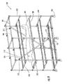
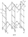
- Figures 1 through 3 illustrate a collapsible cadaver rack 100 in three different positions in accordance with an embodiment of the present invention.
- Figure 1 illustrates collapsible cadaver rack 100 in a first, open and transportable position
- Figure 3 illustrates collapsible cadaver rack 100 in a second, collapsed and storable position.
- Figure 2 shows the collapsible cadaver rack 100 in an intermediate position between the first open position and the second collapsed position.
- Cadaver rack 100 may be constructed of three or more vertically-oriented geometrically-shaped supports 102 with varied spacing. Supports 102 may contain a series of bores 104 as shown in Figure 1 . In some embodiments, collapsible cadaver rack 100 may also contain wheels 106 to facilitate the movement of rack 100. In one embodiment, shown in Figures 1 through 3 , supports 102 may be rectangular in shape and formed from two long vertical members 101 and two shorter horizontal members 103. In various embodiments, supports 102 may be constructed of any material suitable for the intended use of cadaver rack 100 and may be of any geometric shape in order to meet that intended use.
- vertically-oriented geometrically-shaped supports 102 may be configured in the shape of a square, a circle, a triangle, or a parallelogram.
- Figures 1 through 3 show collapsible cadaver rack 100 with three equally-spaced supports 102, any number of supports 102 may be utilized in additional embodiments.
- collapsible cadaver rack 100 may be constructed with two, three, four, or more supports 102.
- supports 102 of collapsible cadaver rack 100 need not be equally spaced as illustrated in Figures 1 through 3 .
- the space between the outer supports and the inner supports may vary from the space between the two inner supports.
- the spacing may be variable.
- Adjacent supports 102 are collapsibly connected by frame members 108.
- adjacent frame members 108 may be connected by a hinge 110.
- eight frame members 108 may be utilized to collapsibly connect each adjacent supports 102, or in additional embodiments, a greater or fewer number of frame members 108 may be used.
- adjacent supports 102 may be connected by four members, twelve members, or sixteen or more members.
- hinges 110 may be equipped with locks (not shown) to ensure that frame members 108 maintain a substantially horizontal orientation while collapsible cadaver rack 100 is in the first open position.
- Horizontal support beams 112 are connected within each support 102.
- the number of horizontal support beams 112 within each support 102 may correspond to the maximum number of cadavers in horizontal orientation that may be transported while using collapsible cadaver rack 100.
- horizontal support beams 112 are placed at the same location within each support as shown in Figures 1 through 3 .
- collapsible cadaver rack 100 may contain varying amounts of horizontal support beams 112 in additional embodiments.
- collapsible cadaver rack 100 may contain two, three, four, or more horizontal support beams 112 per support in various embodiments.
- horizontal support beams 112 may be equipped with a series of bores 114 as illustrated in Figures 1 through 3 .
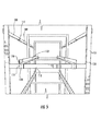
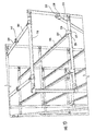
- removable guide rails 116 may be positioned adjacent to horizontal support beams 112. As seen in Figures 1 and 6 , guide rails 116 may extend the length of collapsible cadaver rack 100 on each side, abutting each horizontal support beam 112 of each support 102 that is of a similar height. In some embodiments, removable guide rails 116 contain "U" shaped brackets 118 with holes 120 on either side of the bracket for either receiving a support 102 or a horizontal support beam 112.
- collapsible cadaver rack 100 may further contain transfer boards 121, which may be received by removable guide rails 116. Transfer boards 121 may be used to facilitate the carrying of cadavers or human bodies as shown in Figure 1 .
- Removable guide rails 116 may be constructed in any manner to receive transfer board 121.
- each removable guide rail 116 may be constructed of an "L" shaped rail 122, as seen in Figures 4 and 5 , that allows one side of transfer board 121 to rest firmly on guide rail 116.
- removable guide rail 116 may be created from a "C" shaped rail (not shown). Such a configuration may ensure that a cadaver transfer board which is placed within two "C" shaped rails does not move in either a vertical or horizontal direction.
- a user may move collapsible cadaver rack 100 into a first open position by applying appropriate force to the underside of frame members 108 near hinges 110 such that frame members 108 become substantially horizontal.
- two removable guide rails 116 may be added to abut each similarly positioned horizontal support beam 112.
- Removable guide rails 116 may be placed at varying positions along horizontal support beam 112 or support 102 to accommodate the width of the transfer board utilized. For example, if the user requires the largest width available, removable guide rails 116 may be situated adjacent a portion of support 102.
- bracket 118 may receive a vertical portion of support 102, as shown in Figure 4 . If the user requires a smaller width, guide rails 116 may be positioned at any desired point on support beams 112. For example, in the embodiment where a "U" shaped bracket 118 is utilized on removable guide rails 116, guide rails 116 may be situated such that bracket 118 receives a portion of horizontal support beam 112 as shown in Figure 5 .
- a user may secure the connection between removable guide rails 116 and either rectangular shaped support 102 or support beams 112 with the use of a pin 119 as shown in Figure 4 .
- a pin 119 as shown in Figure 4 .
- holes 120 of bracket 118 may be aligned with a bore 104 or 114 of support 102 or horizontal support beam 112, and pin 119 may be positioned therethrough.
- Suitable pins for use in the present invention could include cotter pins, tab lock pins, pull pins, lynch pins, clevis pins, release pins, detent ring pins, along with others pins.
- any device capable of securing removable guide rail 116 to either support 102 or horizontal support beam 112 may be utilized.
- a screw and nut may be used to secure removable guide rail 116 to either support 102 or horizontal support beam 112.
- guide rails 116 with bracket 118 may be secured to support 102 or horizontal support beam 112 with the use of pins 123 that are each equipped with a bulb portion (not shown) and are connected by a cable 124.
- holes 120 of bracket 118 may be aligned with the bore 104 or 114 of either support 102 or horizontal support beam 112 and the bulb portion of one pin 123 may be inserted through one side of bracket 118 and inside the corresponding bore 104 or 114 causing a secure connection.
- the bulb portion of the opposite pin 123 may be inserted in the opposing side of bracket 118 and either bore 104 or 114 as shown in Figure 6 .
- the user may start by removing guide rails 116 from collapsible cadaver rack 100. In some embodiments, the user then places the appropriate force on hinges 110 and pushes supports 102 in one direction until frame members 108 are in a substantially vertical position as seen in Figure 3 . According to a particular embodiment, when rack 100 is in the second collapsed position, frame members 108 do not extend above or below rack 100.
- removable support braces 126 may be utilized to provide additional support to collapsible cadaver rack 100 when it is in a first open position.
- Removable support braces 126 may be connected to adjacent supports 102, on a single side or on both sides (as shown) and may be oriented horizontally, or diagonally as shown in Figure 6 .
- removable support braces 126 are equipped with holes 128 at each end that are aligned with cavities (not shown) formed in supports 102. Once aligned, any device capable of connecting removable support braces 126 and supports 102 may be utilized, for example, a screw and nut or a pin as discussed above.
- removable support braces 126 may be accomplished in any manner to meet the user's specifications.
- removable support braces 126 may be disconnected from supports 102, and rack 100 may be collapsed as discussed above.
- collapsible cadaver rack 100 may further include a cover 130.
- Cover 130 may be utilized, in some embodiments, to aid in maintaining the temperatures of the cadavers or to protect the cadavers from any outside debris. In other embodiments, cover 130 may be used to keep cadavers out of sight from an outside observer. In some embodiments, cover 130 may be equipped with one or more zippers, to ensure a more secure fit over collapsible cadaver rack 100. Cover 130 may be made of any material known in the art to perform its intended function and may be transparent, opaque, or semi-transparent.
- cover 130 may be constructed of aluminized vinyl, aluminized fiberglass, aluminized Kevlar, aluminized cotton, aluminized polyester, PVC coated vinyl, nylon, or other materials. Those skilled in the art will recognize the wide array of materials that may be used to construct cover 130.
- Figures 9 through 15 show an alternative embodiment in which collapsible cadaver rack 200 comprises vertically-oriented geometrically-shaped supports 210, collapsible frame members 204, wheels 206, removable guide rails 208, and single-end disengageable support braces 210.
- cadaver rack 200 may be oriented in a first open position as shown in Figure 9 , in a second, closed position as shown in Figure 11 , or in an intermediate position as shown in Figure 10 .
- Adjacent supports 202 of collapsible rack 200 are collapsibly connected by frame members 204 and adjacent frame members 204 may be connected by a hinge 212.
- hinge 212 includes a series of holes 214 that are substantially aligned and may receive a cotter pin 216, or other similar securing device, when adjacent collapsible frame members 204 are in a substantially horizontal position.
- Cotter pin 216 may serve to maintain adjacent collapsible frame members 204 in a substantially horizontal orientation when collapsible cadaver rack 200 is in a first position.
- hinge 212 is shown using a cotter pin 216, any item may be utilized to maintain adjacent collapsible frame members 204 in a substantially horizontal orientation.
- suitable items could include a screw and nut, a tab lock pin, a pull pin, a lynch pin, a clevis pin, a release pin, a detent ring pin, or any other item known in the art.
- Vertically-oriented geometrically-shaped supports 202 comprise horizontal support beams 218 within each support 202.
- support beams 218 are placed at the same location within each support 202, as shown in Figures 9 and 10 .
- the number of horizontal support beams 218 within supports 202 may correspond to the maximum number of cadavers or human bodies that may be placed within collapsible cadaver rack 200.
- collapsible cadaver rack 200 When collapsible cadaver rack 200 is in a first open position, removable guide rails 208 may be positioned adjacent horizontal support beams 218 as shown in Figure 9 .
- collapsible cadaver rack 200 may further contain transfer boards 203, which may be received by removable guide rails 208. Transfer boards 203 may be used to facilitate the carrying of cadavers or human bodies as shown in Figure 9 .
- removable guide rails 208 may include rollers 220 that extend the entire length of each guide rail 208 as seen in Figure 13 . Rollers 220 may be utilized to aid in sliding transfer board 203 along removable guide rails 208, when transfer board 203 is utilized. Although Figure 13 illustrates rollers 220 extending the entire length of rack 200, any number of rollers 220 may be used to meet the user's specifications.
- removable guide rail 208 may be constructed in any configuration to meet a user's specification.
- removable guide rail 208 may be constructed of an "L" shaped rail or a "C” shaped rail. Such configurations may ensure that a transfer board 203, when placed on removable guide rails 208, will not move in a vertical or horizontal direction.
- Removable guide rails 208 may also include "U" shaped brackets 222 at either end of each rail 208, as seen in Figures 13 and 14 .
- brackets 222 contain flexible indentions 224 and a raised tab 226.
- support braces 210 may be used to provide additional support to collapsible cadaver rack 200 when it is in a first open position.
- Removable support braces 210 may be connected to adjacent supports 202, and may be oriented horizontally, or diagonally as shown in Figure 9 .
- support braces 210 have a first end 228 and a second end 230 that are connected to hinges 232, 234 located on supports 202.
- Hinge 234 contains a set of holes 236 and second end 230 contains a hole 238 (best shown in Figure 10 ) such that when second end 230 is properly positioned with hinge 234, the series of holes 236 and the hole of second end 230 are aligned and may receive a release pin 240 as shown in Figure 15 .
- a release pin 240 is described and shown, any item that may maintain the connection between second end 230 and hinge 234 may be used.
- hinge 232 and first end 228 may have similar holes to receive a pin as described above.
- support braces 210 may be fully removable from collapsible cadaver rack 200.
- supports 202, frame members 204, support braces 210, and horizontal support beams 218 may have a tubular construction. This construction may allow rack 200 to be lighter and easier to move when it is either in a first or second position.
- the tubular construction of the above described components may allow for the addition of steel conduits (not shown) to be placed inside each component. Steel conduits may add to the stability of cadaver rack 200 and may allow for the transport of more or heavier cadavers.
- a user may move collapsible cadaver rack 200 into a first position by applying appropriate force to hinges 212, such that frame members 204 are substantially horizontal.
- a user may add a cotter pin to holes 214 of hinge 212, as described above, to secure frame members 204 in their horizontal orientation.
- a user may align the hole 238 of second end 230 of support brace 210 with the holes 236 of hinge 234 and then position a release pin therethrough.
- a user may then place removable guide rails 208 along similarly situated horizontal support beams 218 of supports 202, as shown in Figures 9 and 13 .
- Removable guide rails 208 may be placed at any position along horizontal support beam 218 to meet the user's specification and to accommodate a transfer board 203 as shown in Figure 9 .
- a user may decide to position each guide rail 208 on horizontal support beam 218 adjacent to supports 202.
- a user applies downward force to "U" shaped bracket 222, such that it receives support beam 218.
- flexible indentions 224 are compressed against support beam 218 such that they are substantially flush with the inside of bracket 222.
- the user may start by removing guide rails 208 from collapsible cadaver rack 200 by applying an appropriate amount of upward force to "U" shaped bracket 222 such that it is dislodged from support beams 218.
- a user may then remove release pin 240 from hinge 234 and second end 230 of support brace 210, allowing support brace 210 to swing about its first hinge 232 as shown in Figure 10 .
- a user may also remove cotter pin 216 from hinge 212 of collapsible frame members 204. Once cotter pin 216 is removed, the user may then place an appropriate amount of force on hinges 212 and push supports 202 in one direction until frame members 204 are in a substantially vertical position as seen in Figure 11 .
- collapsible cadaver racks may vary based on the user's specifications. For example, if a collapsible cadaver rack is used to transport three cadavers and is in a first open position, the collapsible rack may have a length between about 5 feet and 10 feet, a width between about 1.5 feet and 4 feet, and a height between about 5 feet and 8 feet in some embodiments. In other embodiments, where the collapsible rack is used to transport three cadavers, in a first, open position, collapsible rack 10 may have a length between about 6 feet and 8 feet, a width between 2 feet and 3 feet and a height between 6 feet and 7 feet.
- the collapsible cadaver racks described above may have a greater width to support two or more adjacent transfer boards at the same horizontal position.
- Such a configuration may include a greater number of guide rails attached to each support beam in order to accommodate each additional transfer board.
- the collapsible cadaver racks described above may be constructed of any material suitable for transporting the transfer boards carrying cadavers.
- the collapsible cadaver racks described above may be constructed of steel, including stainless steel, aluminum, plastic, fiberglass, or a combination of materials. Those of ordinary skill in the art will recognize the materials that may be utilized for the collapsible cadaver rack to perform its intended functions.
- the collapsible cadaver racks described above may contain various colors in order to identify the cadavers located on the rack. For example, in some embodiments, a collapsible cadaver rack may be colored red to indicate that there is a biohazard present. In other embodiments, the collapsible cadaver racks may be colored blue to indicate that the cadavers should be transported to a particular location. Those skilled in the art will recognize the variety of colors and designations those colors may make when associated with the collapsible cadaver racks described above.
Landscapes
- Health & Medical Sciences (AREA)
- Life Sciences & Earth Sciences (AREA)
- Animal Behavior & Ethology (AREA)
- General Health & Medical Sciences (AREA)
- Public Health (AREA)
- Veterinary Medicine (AREA)
- Warehouses Or Storage Devices (AREA)
- Details Of Rigid Or Semi-Rigid Containers (AREA)
Applications Claiming Priority (1)
| Application Number | Priority Date | Filing Date | Title |
|---|---|---|---|
| US12/558,209 US10172749B2 (en) | 2009-09-11 | 2009-09-11 | Collapsible cadaver rack |
Publications (3)
| Publication Number | Publication Date |
|---|---|
| EP2295021A2 true EP2295021A2 (de) | 2011-03-16 |
| EP2295021A3 EP2295021A3 (de) | 2012-01-04 |
| EP2295021B1 EP2295021B1 (de) | 2013-05-29 |
Family
ID=43333287
Family Applications (1)
| Application Number | Title | Priority Date | Filing Date |
|---|---|---|---|
| EP10163438.4A Active EP2295021B1 (de) | 2009-09-11 | 2010-05-20 | Zusammenklappbares Leichenregal |
Country Status (2)
| Country | Link |
|---|---|
| US (2) | US10172749B2 (de) |
| EP (1) | EP2295021B1 (de) |
Families Citing this family (11)
| Publication number | Priority date | Publication date | Assignee | Title |
|---|---|---|---|---|
| US10172749B2 (en) * | 2009-09-11 | 2019-01-08 | Michael P. Richardson | Collapsible cadaver rack |
| US10024050B2 (en) * | 2011-12-07 | 2018-07-17 | Cpi Technologies, Llc | Solar panel truss deployable from moving carrier |
| WO2013134914A1 (zh) * | 2012-03-12 | 2013-09-19 | Kin Chung Ng | 易于折叠的折叠框架 |
| DE102018126024A1 (de) * | 2018-10-19 | 2020-04-23 | Nordischer Maschinenbau Rud. Baader Gmbh + Co. Kg | Ladungshilfe für gestapelte und mit lebenden Geflügeltieren zu befüllende Transportbehälter |
| FI128941B (en) * | 2019-10-23 | 2021-03-31 | Vericrea | Pallet, transport device and system for transporting goods |
| DE102019129026A1 (de) * | 2019-10-28 | 2021-04-29 | Djedovic Dzemil | Mobile Vorrichtung zum temporären Kühlen von Gütern |
| USD997885S1 (en) * | 2021-04-20 | 2023-09-05 | Inter-Rail Transport, Inc. | Safety transition ladder |
| WO2023031660A1 (en) * | 2021-08-30 | 2023-03-09 | Manas Ghosh | A portable multi-tier single or double winged bed assembly |
| JP3235873U (ja) * | 2021-10-29 | 2022-01-14 | 曹欣 | 搬送と組立に適合な折畳み型載物フレーム |
| CN115641789B (zh) * | 2022-12-07 | 2026-01-13 | 常州灵特尔轻便展示系统有限公司 | 折叠展架 |
| US12305905B2 (en) | 2023-08-25 | 2025-05-20 | Acela, Inc. | Refrigerated portable room system |
Family Cites Families (106)
| Publication number | Priority date | Publication date | Assignee | Title |
|---|---|---|---|---|
| US471697A (en) * | 1892-03-29 | mosbaceer | ||
| US148713A (en) * | 1874-03-17 | Improvement in folding clothes-horses | ||
| US388281A (en) * | 1888-08-21 | Clothes-drier | ||
| US874159A (en) * | 1907-01-05 | 1907-12-17 | Heinrich Brusis | Stretcher-supporting frame. |
| US909336A (en) * | 1908-02-13 | 1909-01-12 | Joseph F Riedy | Display-rack. |
| US982477A (en) * | 1909-07-13 | 1911-01-24 | Eugene P Lynch | Portable work-supporting rack. |
| US968201A (en) * | 1909-08-18 | 1910-08-23 | Woodford Shannon | Display-rack. |
| GB191421085A (en) | 1914-10-16 | 1915-10-14 | Otto Simonis | Improvements in Portable Fittings or Supports for Ambulance Stretchers. |
| US1178258A (en) * | 1915-12-08 | 1916-04-04 | Robert Sheldon Moore | Portable shelf for hearses. |
| US1407607A (en) * | 1921-05-23 | 1922-02-21 | Wakeham Gertrude Watson | Rack |
| US1563057A (en) * | 1922-05-03 | 1925-11-24 | Fisk Rubber Co | Handling truck |
| US1626507A (en) * | 1923-04-28 | 1927-04-26 | Camper James Harrison | Household article |
| US1727048A (en) * | 1925-12-05 | 1929-09-03 | Mabel H Cady | Folding shelf |
| US1737971A (en) * | 1927-03-24 | 1929-12-03 | Law Albert | Tubular rack |
| US1716466A (en) * | 1927-07-05 | 1929-06-11 | Ernest M Sims | Collapsible stand |
| US1929467A (en) * | 1931-12-14 | 1933-10-10 | Lyon Metal Products Inc | Rack and shelf construction |
| US1991397A (en) * | 1932-12-31 | 1935-02-19 | Henry L Schroeder | Metallic frame structure |
| US2398730A (en) * | 1945-01-16 | 1946-04-16 | Chrysler Corp | Litter-carrying vehicle |
| US2456024A (en) * | 1945-03-05 | 1948-12-14 | Du Pont | Foldable stretcher carrier for ambulances |
| US2520128A (en) * | 1945-12-06 | 1950-08-29 | Walton W Cushman | Litter rack |
| US2440513A (en) * | 1946-09-03 | 1948-04-27 | Kaelin Gottfried | Smokehouse rack |
| US2599670A (en) * | 1950-02-01 | 1952-06-10 | George G Thomas | Foldable scaffold for household uses |
| US2748955A (en) * | 1951-08-02 | 1956-06-05 | Anselmo Charles | Collapsible rack |
| US2726407A (en) * | 1951-10-09 | 1955-12-13 | Dean Mfg Co Inc | Cot and supporting structure |
| US2774609A (en) * | 1954-01-04 | 1956-12-18 | Raymond C Winger | Dolly with disassembly facilitating means |
| US2969863A (en) * | 1956-05-21 | 1961-01-31 | Rapids Standard Co Inc | Conveyorized storage racks |
| US2978225A (en) * | 1957-01-09 | 1961-04-04 | Jet Heet Inc | Thermal blanket |
| US2950014A (en) * | 1957-03-07 | 1960-08-23 | Alvey Ferguson Co | Conveyor-type article storage rack having lift-out rail sections |
| US3221216A (en) * | 1962-07-26 | 1965-11-30 | Murray Mfg Corp | Meter mount |
| US3240505A (en) * | 1964-05-06 | 1966-03-15 | Swift & Co | Meat-hanging truck |
| US3358300A (en) * | 1966-05-23 | 1967-12-19 | Lockheed Aircraft Corp | Mounting and supporting apparatus for litters |
| US3567039A (en) * | 1967-02-07 | 1971-03-02 | George Q Evans | Elevator conveyor and storage rack system |
| US3463265A (en) * | 1968-07-08 | 1969-08-26 | Fairfield Ind Inc | Telescoping collapsible platform support |
| US3527174A (en) * | 1968-10-11 | 1970-09-08 | Hamilton Cosco Inc | Foldable serving cart |
| US3559339A (en) * | 1968-11-04 | 1971-02-02 | Robert W Worley | Collapsible plant stake assembly |
| CH512376A (fr) | 1969-08-26 | 1971-09-15 | Rufener Marcel | Conteneur pour le transport de denrées périssables |
| US3834549A (en) * | 1972-09-25 | 1974-09-10 | Gordon Tube Prod Co Inc | Structural system |
| US4006500A (en) * | 1975-03-13 | 1977-02-08 | Andre Bonifay | Stretcher holder device for ambulances |
| US3967327A (en) * | 1975-02-10 | 1976-07-06 | Severson Harvey M | Foldable bed |
| US4132262A (en) * | 1977-01-17 | 1979-01-02 | Joan Wibell | Heating and cooling blanket |
| US4178032A (en) * | 1978-05-01 | 1979-12-11 | United Technologies Corporation | Apparatus for synchronously elevating and lowering air-ambulance litter with crash attenuation capability |
| CA1094528A (en) * | 1978-10-31 | 1981-01-27 | Entreprises Rotot Ltee (Les) | Collapsible support mechanism and devices made therewith |
| US4453641A (en) * | 1980-04-01 | 1984-06-12 | Interlake, Inc. | Gravity-feed storage and delivery system |
| USD267373S (en) * | 1980-06-30 | 1982-12-28 | Behrens Irene A | Display rack for clothing and accessories |
| US4397432A (en) * | 1981-06-02 | 1983-08-09 | The Boeing Company | Adjustable litter support assembly |
| US4512591A (en) * | 1982-07-06 | 1985-04-23 | Plante Jean Paul | Hand truck |
| US4485578A (en) * | 1982-07-21 | 1984-12-04 | Novey Richard T | Adjustable supports for fishing rods and the like |
| US4691762A (en) | 1983-04-01 | 1987-09-08 | Life Support Systems, Inc. | Personal temperature control system |
| US4522130A (en) * | 1983-04-01 | 1985-06-11 | Roy Worthington | Collapsible tea cart |
| DE3568131D1 (en) * | 1984-09-26 | 1989-03-16 | Schaefer Gmbh Fritz | Rack |
| JPH04105609A (ja) * | 1990-08-27 | 1992-04-07 | Higashinihonbashi Riyuutsuu Center:Kk | 衣類輸送用ハンガーラック |
| US5241951B1 (en) * | 1990-09-05 | 1999-07-06 | Breg Inc | Therapeutic nonambient temperature fluid circulation system |
| US5259518A (en) * | 1991-08-09 | 1993-11-09 | Ncm International, Inc. | Merchandising system |
| DE4131368A1 (de) * | 1991-09-20 | 1993-03-25 | Scherfeder Drahtwarenfabrik Gm | Fahrbares transport- und verkaufsregal |
| US5131547A (en) * | 1991-11-26 | 1992-07-21 | Kenneth Goldberg | Collapsible storage rack |
| US5295591A (en) * | 1992-09-04 | 1994-03-22 | Slater Robert C | Storage or display rack |
| US5383629A (en) * | 1992-10-07 | 1995-01-24 | Air Methods Corporation International | Emergency medical system |
| US5372339A (en) * | 1992-10-07 | 1994-12-13 | Air Methods Corporation International | Multi-tiered litter rack system |
| US5279430A (en) * | 1993-05-13 | 1994-01-18 | Unr Industries, Inc. | Storage rack with wire track beam |
| DE9411381U1 (de) * | 1994-07-14 | 1994-11-03 | Vogler, Sven, 42551 Velbert | Zusammenfaltbares Regal |
| US5957309A (en) * | 1995-02-10 | 1999-09-28 | Hall; Donald M. | Tray rack |
| US5613730A (en) * | 1995-03-29 | 1997-03-25 | Buie; Dan | Temperature controlled seat cover assembly |
| CH693842A5 (de) | 1995-06-13 | 2004-03-15 | Schnydrig Ag | Tragbahrengestell. |
| US5577622A (en) * | 1995-07-14 | 1996-11-26 | Van Bloem, Inc. | Merchandising display rack assembly |
| AU1349697A (en) | 1995-12-29 | 1997-07-28 | Life Resuscitation Technologies, Inc. | Total body cooling system |
| AU5364798A (en) | 1996-11-25 | 1998-06-22 | Kinetic Concepts, Inc. | Temperature control for use with patient supports |
| US5806335A (en) * | 1997-02-13 | 1998-09-15 | Pabban Development Inc | Cold therapy device |
| US5873642A (en) * | 1997-10-10 | 1999-02-23 | Grass America, Inc. | Hanging file bar support assembly for a drawer |
| US6095347A (en) * | 1997-12-15 | 2000-08-01 | Chrysler Corporation | Adjustably mounted elongated conveyor and transverse picking tray |
| USRE38517E1 (en) * | 1998-01-14 | 2004-05-18 | Unex Conveying Systems Inc. | Universal flow track system |
| US6132158A (en) * | 1998-01-14 | 2000-10-17 | Unex Manufacturing Inc. | Universal flow track system |
| US6186725B1 (en) * | 1999-05-25 | 2001-02-13 | Konstant Products, Inc. | Container pick and return system |
| US6230908B1 (en) * | 1999-09-01 | 2001-05-15 | Dell Usa, L.P. | Flow rack with reverse flow limiting device |
| US6431808B1 (en) * | 2000-11-30 | 2002-08-13 | Unarco Material Handling, Inc. | Storage rack having roller track |
| US6520357B1 (en) * | 2001-01-10 | 2003-02-18 | Interlake Material Handling, Inc. | Rack with members attached by clips |
| DE20103240U1 (de) * | 2001-02-23 | 2001-07-05 | Wang, Wen-Tsan, Taipeh/T'ai-pei | Zusammenklappbarer Kleiderständer |
| US6776298B2 (en) * | 2001-04-03 | 2004-08-17 | Ridg-U-Rak, Inc. | Front beam and tension rod arrangement for push back rack storage system |
| US6588608B2 (en) * | 2001-06-01 | 2003-07-08 | Konstant Products, Inc. | Storage system with automatic elevator |
| US6669213B2 (en) * | 2001-07-31 | 2003-12-30 | Hafele America Co. | Industrial transportation and storage cart |
| US6923606B2 (en) * | 2002-01-30 | 2005-08-02 | Arinc Incorporated | Medical evacuation patient support pallet |
| US6604640B1 (en) * | 2002-05-31 | 2003-08-12 | Stow International N.V. | Storage system |
| US6951441B2 (en) * | 2002-08-28 | 2005-10-04 | Unarco Material Handling, Inc. | Storage rack having roller track supported on horizontally extending front and back beams |
| WO2004065267A2 (en) * | 2003-01-21 | 2004-08-05 | Wenger Corporation | Riser cart |
| CA2457568A1 (en) * | 2003-02-12 | 2004-08-12 | B-O-F Corporation | Method and apparatus for converting gondola shelf to gravity feed shelf |
| TW579787U (en) * | 2003-05-16 | 2004-03-11 | Jing-Fei Chen | Improved folding structure of shelf |
| US6851564B2 (en) * | 2003-05-28 | 2005-02-08 | Kelvin Kin-Chung Ng | Multi-plane compound folding frame |
| US20060048520A1 (en) * | 2004-09-09 | 2006-03-09 | U-Long Co., Ltd. | Cooling/heating pad |
| US20070012837A1 (en) * | 2005-06-13 | 2007-01-18 | Stuart Timothy S | Supporting surface bracket |
| US7568241B2 (en) * | 2005-09-29 | 2009-08-04 | Roberts Thomas E | Emergency patient support and transport system |
| AU2006337095B2 (en) * | 2005-10-21 | 2011-11-03 | Gentherm Medical, Llc | Patient temperature control system with variable gradient warming/cooling |
| GB0521786D0 (en) * | 2005-10-26 | 2005-12-07 | Meehan Gerard M | Mobile garment carrier |
| US20070118194A1 (en) * | 2005-11-22 | 2007-05-24 | Breg, Inc. | Non-ambient temperature therapy system with automatic treatment temperature maintenance |
| CN2865426Y (zh) * | 2006-01-26 | 2007-02-07 | 绿星(福州)居室用品有限公司 | 折叠柜支撑架 |
| AT9009U1 (de) * | 2006-02-01 | 2007-04-15 | Emcools Emergency Medical Cool | Einrichtung zum kühlen des körpers von personen oder dergl. |
| US7328926B1 (en) * | 2006-07-28 | 2008-02-12 | Myers Will J | Patient support system for medical transport vehicles |
| US20080063771A1 (en) * | 2006-09-12 | 2008-03-13 | Dumm Richard H | Heat exchanger unit |
| US7637220B2 (en) * | 2007-01-10 | 2009-12-29 | Kuang-Huan Fu | Collapsible shelf device |
| GB0708566D0 (en) | 2007-05-03 | 2007-06-13 | Nutwell Logistics Ltd | Mobile cooling unit |
| US9044371B2 (en) * | 2007-06-13 | 2015-06-02 | Trailerlogic, Llc | Scalable and portable human remains cold storage system |
| JP5013096B2 (ja) | 2007-12-04 | 2012-08-29 | 株式会社ダイフク | 流動棚装置 |
| JP2009203032A (ja) | 2008-02-28 | 2009-09-10 | Nippon Zeon Co Ltd | ラック |
| US20100300993A1 (en) * | 2008-11-26 | 2010-12-02 | Edwin Ho | Modular utility rack |
| US20110240571A1 (en) * | 2008-11-26 | 2011-10-06 | Edwin Ho | Modular utility rack |
| US8210312B1 (en) * | 2009-06-25 | 2012-07-03 | Tetreault Jr Adrien R | Mobile work platform |
| US8256629B2 (en) * | 2009-06-25 | 2012-09-04 | Shou Qiang Zhu | Foldable and portable storage shelf |
| US10172749B2 (en) * | 2009-09-11 | 2019-01-08 | Michael P. Richardson | Collapsible cadaver rack |
-
2009
- 2009-09-11 US US12/558,209 patent/US10172749B2/en active Active
-
2010
- 2010-05-20 EP EP10163438.4A patent/EP2295021B1/de active Active
-
2019
- 2019-01-08 US US16/242,996 patent/US11020292B2/en active Active
Non-Patent Citations (1)
| Title |
|---|
| None |
Also Published As
| Publication number | Publication date |
|---|---|
| EP2295021B1 (de) | 2013-05-29 |
| US10172749B2 (en) | 2019-01-08 |
| US11020292B2 (en) | 2021-06-01 |
| US20190142657A1 (en) | 2019-05-16 |
| EP2295021A3 (de) | 2012-01-04 |
| US20110062098A1 (en) | 2011-03-17 |
Similar Documents
| Publication | Publication Date | Title |
|---|---|---|
| EP2295021B1 (de) | Zusammenklappbares Leichenregal | |
| RU2617218C2 (ru) | Устройство для хранения множества предметов, таких как ящики | |
| US7156273B2 (en) | Convertible cargo container system | |
| US5941383A (en) | Collapsible golf bag | |
| US8127381B2 (en) | Collapsible litter apparatus, system and method | |
| US6036219A (en) | Expandable transport cart | |
| US8256630B2 (en) | Foldable and portable storage shelf | |
| ES2220240T3 (es) | Sistema de transporte y almacenamiento. | |
| ES2774077T3 (es) | Un dispositivo para soportar cargas | |
| US11051998B2 (en) | Portable and collapsible support structures and related methods | |
| US8042819B2 (en) | Folding cart for galley | |
| EP2274214A2 (de) | Behälter zur handhabung von schüttgut | |
| US7959390B2 (en) | Vehicle trunk organizer | |
| SK8884Y1 (sk) | Skladateľný viacposchodový obal s flexibilnými vložiteľnými bunkami na prepravu tovaru | |
| EP3774492B1 (de) | Handwagen | |
| US20180295981A1 (en) | Vertical folding shelf | |
| WO2008036430A1 (en) | Trunk loading apparatus for a wheelchair | |
| GB2190895A (en) | Interengageable pallets | |
| US7293680B1 (en) | Lifting device | |
| MX2014009197A (es) | Carro plegable para estantes. | |
| US9226589B2 (en) | Collapsible bed system | |
| US20140196988A1 (en) | Tree Climbing Device And Stand | |
| US931529A (en) | Convertible boat and tent. | |
| FI120232B (fi) | Menetelmä kelojen ja konttien lastaamiseksi laivaan ja teline käytettäväksi kelojen ja konttien lastaamisessa laivaan, kuljettamiseksi laivalla ja purkamiseksi laivasta | |
| SU586066A1 (ru) | Контейнер |
Legal Events
| Date | Code | Title | Description |
|---|---|---|---|
| PUAI | Public reference made under article 153(3) epc to a published international application that has entered the european phase |
Free format text: ORIGINAL CODE: 0009012 |
|
| AK | Designated contracting states |
Kind code of ref document: A2 Designated state(s): AL AT BE BG CH CY CZ DE DK EE ES FI FR GB GR HR HU IE IS IT LI LT LU LV MC MK MT NL NO PL PT RO SE SI SK SM TR |
|
| AX | Request for extension of the european patent |
Extension state: BA ME RS |
|
| TPAC | Observations filed by third parties |
Free format text: ORIGINAL CODE: EPIDOSNTIPA |
|
| PUAL | Search report despatched |
Free format text: ORIGINAL CODE: 0009013 |
|
| AK | Designated contracting states |
Kind code of ref document: A3 Designated state(s): AL AT BE BG CH CY CZ DE DK EE ES FI FR GB GR HR HU IE IS IT LI LT LU LV MC MK MT NL NO PL PT RO SE SI SK SM TR |
|
| AX | Request for extension of the european patent |
Extension state: BA ME RS |
|
| RIC1 | Information provided on ipc code assigned before grant |
Ipc: A61G 21/00 20060101AFI20111130BHEP Ipc: A61G 1/013 20060101ALN20111130BHEP Ipc: A47B 43/00 20060101ALI20111130BHEP |
|
| TPAC | Observations filed by third parties |
Free format text: ORIGINAL CODE: EPIDOSNTIPA |
|
| 17P | Request for examination filed |
Effective date: 20120417 |
|
| GRAP | Despatch of communication of intention to grant a patent |
Free format text: ORIGINAL CODE: EPIDOSNIGR1 |
|
| RIC1 | Information provided on ipc code assigned before grant |
Ipc: A61G 1/013 20060101ALN20120612BHEP Ipc: A47B 43/00 20060101ALI20120612BHEP Ipc: A61G 21/00 20060101AFI20120612BHEP |
|
| GRAP | Despatch of communication of intention to grant a patent |
Free format text: ORIGINAL CODE: EPIDOSNIGR1 |
|
| RIC1 | Information provided on ipc code assigned before grant |
Ipc: A61G 21/00 20060101AFI20121122BHEP Ipc: A61G 1/013 20060101ALN20121122BHEP Ipc: A47B 43/00 20060101ALI20121122BHEP |
|
| GRAS | Grant fee paid |
Free format text: ORIGINAL CODE: EPIDOSNIGR3 |
|
| GRAA | (expected) grant |
Free format text: ORIGINAL CODE: 0009210 |
|
| AK | Designated contracting states |
Kind code of ref document: B1 Designated state(s): AL AT BE BG CH CY CZ DE DK EE ES FI FR GB GR HR HU IE IS IT LI LT LU LV MC MK MT NL NO PL PT RO SE SI SK SM TR |
|
| AX | Request for extension of the european patent |
Extension state: BA ME RS |
|
| REG | Reference to a national code |
Ref country code: GB Ref legal event code: FG4D |
|
| REG | Reference to a national code |
Ref country code: CH Ref legal event code: EP |
|
| REG | Reference to a national code |
Ref country code: AT Ref legal event code: REF Ref document number: 613904 Country of ref document: AT Kind code of ref document: T Effective date: 20130615 |
|
| REG | Reference to a national code |
Ref country code: IE Ref legal event code: FG4D |
|
| REG | Reference to a national code |
Ref country code: DE Ref legal event code: R096 Ref document number: 602010007234 Country of ref document: DE Effective date: 20130801 |
|
| REG | Reference to a national code |
Ref country code: AT Ref legal event code: MK05 Ref document number: 613904 Country of ref document: AT Kind code of ref document: T Effective date: 20130529 |
|
| REG | Reference to a national code |
Ref country code: LT Ref legal event code: MG4D |
|
| PG25 | Lapsed in a contracting state [announced via postgrant information from national office to epo] |
Ref country code: GR Free format text: LAPSE BECAUSE OF FAILURE TO SUBMIT A TRANSLATION OF THE DESCRIPTION OR TO PAY THE FEE WITHIN THE PRESCRIBED TIME-LIMIT Effective date: 20130830 Ref country code: PT Free format text: LAPSE BECAUSE OF FAILURE TO SUBMIT A TRANSLATION OF THE DESCRIPTION OR TO PAY THE FEE WITHIN THE PRESCRIBED TIME-LIMIT Effective date: 20130930 Ref country code: SE Free format text: LAPSE BECAUSE OF FAILURE TO SUBMIT A TRANSLATION OF THE DESCRIPTION OR TO PAY THE FEE WITHIN THE PRESCRIBED TIME-LIMIT Effective date: 20130529 Ref country code: LT Free format text: LAPSE BECAUSE OF FAILURE TO SUBMIT A TRANSLATION OF THE DESCRIPTION OR TO PAY THE FEE WITHIN THE PRESCRIBED TIME-LIMIT Effective date: 20130529 Ref country code: FI Free format text: LAPSE BECAUSE OF FAILURE TO SUBMIT A TRANSLATION OF THE DESCRIPTION OR TO PAY THE FEE WITHIN THE PRESCRIBED TIME-LIMIT Effective date: 20130529 Ref country code: NO Free format text: LAPSE BECAUSE OF FAILURE TO SUBMIT A TRANSLATION OF THE DESCRIPTION OR TO PAY THE FEE WITHIN THE PRESCRIBED TIME-LIMIT Effective date: 20130829 Ref country code: SI Free format text: LAPSE BECAUSE OF FAILURE TO SUBMIT A TRANSLATION OF THE DESCRIPTION OR TO PAY THE FEE WITHIN THE PRESCRIBED TIME-LIMIT Effective date: 20130529 Ref country code: IS Free format text: LAPSE BECAUSE OF FAILURE TO SUBMIT A TRANSLATION OF THE DESCRIPTION OR TO PAY THE FEE WITHIN THE PRESCRIBED TIME-LIMIT Effective date: 20130929 Ref country code: ES Free format text: LAPSE BECAUSE OF FAILURE TO SUBMIT A TRANSLATION OF THE DESCRIPTION OR TO PAY THE FEE WITHIN THE PRESCRIBED TIME-LIMIT Effective date: 20130909 Ref country code: AT Free format text: LAPSE BECAUSE OF FAILURE TO SUBMIT A TRANSLATION OF THE DESCRIPTION OR TO PAY THE FEE WITHIN THE PRESCRIBED TIME-LIMIT Effective date: 20130529 |
|
| REG | Reference to a national code |
Ref country code: NL Ref legal event code: VDEP Effective date: 20130529 |
|
| PG25 | Lapsed in a contracting state [announced via postgrant information from national office to epo] |
Ref country code: PL Free format text: LAPSE BECAUSE OF FAILURE TO SUBMIT A TRANSLATION OF THE DESCRIPTION OR TO PAY THE FEE WITHIN THE PRESCRIBED TIME-LIMIT Effective date: 20130529 Ref country code: BG Free format text: LAPSE BECAUSE OF FAILURE TO SUBMIT A TRANSLATION OF THE DESCRIPTION OR TO PAY THE FEE WITHIN THE PRESCRIBED TIME-LIMIT Effective date: 20130829 Ref country code: HR Free format text: LAPSE BECAUSE OF FAILURE TO SUBMIT A TRANSLATION OF THE DESCRIPTION OR TO PAY THE FEE WITHIN THE PRESCRIBED TIME-LIMIT Effective date: 20130529 |
|
| PG25 | Lapsed in a contracting state [announced via postgrant information from national office to epo] |
Ref country code: LV Free format text: LAPSE BECAUSE OF FAILURE TO SUBMIT A TRANSLATION OF THE DESCRIPTION OR TO PAY THE FEE WITHIN THE PRESCRIBED TIME-LIMIT Effective date: 20130529 |
|
| PG25 | Lapsed in a contracting state [announced via postgrant information from national office to epo] |
Ref country code: BE Free format text: LAPSE BECAUSE OF FAILURE TO SUBMIT A TRANSLATION OF THE DESCRIPTION OR TO PAY THE FEE WITHIN THE PRESCRIBED TIME-LIMIT Effective date: 20130529 Ref country code: CZ Free format text: LAPSE BECAUSE OF FAILURE TO SUBMIT A TRANSLATION OF THE DESCRIPTION OR TO PAY THE FEE WITHIN THE PRESCRIBED TIME-LIMIT Effective date: 20130529 Ref country code: SK Free format text: LAPSE BECAUSE OF FAILURE TO SUBMIT A TRANSLATION OF THE DESCRIPTION OR TO PAY THE FEE WITHIN THE PRESCRIBED TIME-LIMIT Effective date: 20130529 Ref country code: EE Free format text: LAPSE BECAUSE OF FAILURE TO SUBMIT A TRANSLATION OF THE DESCRIPTION OR TO PAY THE FEE WITHIN THE PRESCRIBED TIME-LIMIT Effective date: 20130529 Ref country code: DK Free format text: LAPSE BECAUSE OF FAILURE TO SUBMIT A TRANSLATION OF THE DESCRIPTION OR TO PAY THE FEE WITHIN THE PRESCRIBED TIME-LIMIT Effective date: 20130529 |
|
| PG25 | Lapsed in a contracting state [announced via postgrant information from national office to epo] |
Ref country code: RO Free format text: LAPSE BECAUSE OF FAILURE TO SUBMIT A TRANSLATION OF THE DESCRIPTION OR TO PAY THE FEE WITHIN THE PRESCRIBED TIME-LIMIT Effective date: 20130529 Ref country code: NL Free format text: LAPSE BECAUSE OF FAILURE TO SUBMIT A TRANSLATION OF THE DESCRIPTION OR TO PAY THE FEE WITHIN THE PRESCRIBED TIME-LIMIT Effective date: 20130529 |
|
| PLBE | No opposition filed within time limit |
Free format text: ORIGINAL CODE: 0009261 |
|
| STAA | Information on the status of an ep patent application or granted ep patent |
Free format text: STATUS: NO OPPOSITION FILED WITHIN TIME LIMIT |
|
| 26N | No opposition filed |
Effective date: 20140303 |
|
| REG | Reference to a national code |
Ref country code: DE Ref legal event code: R097 Ref document number: 602010007234 Country of ref document: DE Effective date: 20140303 |
|
| PG25 | Lapsed in a contracting state [announced via postgrant information from national office to epo] |
Ref country code: LU Free format text: LAPSE BECAUSE OF FAILURE TO SUBMIT A TRANSLATION OF THE DESCRIPTION OR TO PAY THE FEE WITHIN THE PRESCRIBED TIME-LIMIT Effective date: 20140520 |
|
| REG | Reference to a national code |
Ref country code: CH Ref legal event code: PL |
|
| PG25 | Lapsed in a contracting state [announced via postgrant information from national office to epo] |
Ref country code: LI Free format text: LAPSE BECAUSE OF NON-PAYMENT OF DUE FEES Effective date: 20140531 Ref country code: CH Free format text: LAPSE BECAUSE OF NON-PAYMENT OF DUE FEES Effective date: 20140531 |
|
| REG | Reference to a national code |
Ref country code: IE Ref legal event code: MM4A |
|
| PG25 | Lapsed in a contracting state [announced via postgrant information from national office to epo] |
Ref country code: IE Free format text: LAPSE BECAUSE OF NON-PAYMENT OF DUE FEES Effective date: 20140520 |
|
| PG25 | Lapsed in a contracting state [announced via postgrant information from national office to epo] |
Ref country code: MT Free format text: LAPSE BECAUSE OF FAILURE TO SUBMIT A TRANSLATION OF THE DESCRIPTION OR TO PAY THE FEE WITHIN THE PRESCRIBED TIME-LIMIT Effective date: 20130529 |
|
| REG | Reference to a national code |
Ref country code: FR Ref legal event code: PLFP Year of fee payment: 7 |
|
| PG25 | Lapsed in a contracting state [announced via postgrant information from national office to epo] |
Ref country code: SM Free format text: LAPSE BECAUSE OF FAILURE TO SUBMIT A TRANSLATION OF THE DESCRIPTION OR TO PAY THE FEE WITHIN THE PRESCRIBED TIME-LIMIT Effective date: 20130529 |
|
| PG25 | Lapsed in a contracting state [announced via postgrant information from national office to epo] |
Ref country code: CY Free format text: LAPSE BECAUSE OF FAILURE TO SUBMIT A TRANSLATION OF THE DESCRIPTION OR TO PAY THE FEE WITHIN THE PRESCRIBED TIME-LIMIT Effective date: 20130529 Ref country code: MC Free format text: LAPSE BECAUSE OF NON-PAYMENT OF DUE FEES Effective date: 20130529 |
|
| PG25 | Lapsed in a contracting state [announced via postgrant information from national office to epo] |
Ref country code: HU Free format text: LAPSE BECAUSE OF FAILURE TO SUBMIT A TRANSLATION OF THE DESCRIPTION OR TO PAY THE FEE WITHIN THE PRESCRIBED TIME-LIMIT; INVALID AB INITIO Effective date: 20100520 Ref country code: TR Free format text: LAPSE BECAUSE OF FAILURE TO SUBMIT A TRANSLATION OF THE DESCRIPTION OR TO PAY THE FEE WITHIN THE PRESCRIBED TIME-LIMIT Effective date: 20130529 |
|
| REG | Reference to a national code |
Ref country code: FR Ref legal event code: PLFP Year of fee payment: 8 |
|
| REG | Reference to a national code |
Ref country code: FR Ref legal event code: PLFP Year of fee payment: 9 |
|
| PG25 | Lapsed in a contracting state [announced via postgrant information from national office to epo] |
Ref country code: MK Free format text: LAPSE BECAUSE OF FAILURE TO SUBMIT A TRANSLATION OF THE DESCRIPTION OR TO PAY THE FEE WITHIN THE PRESCRIBED TIME-LIMIT Effective date: 20130529 |
|
| PG25 | Lapsed in a contracting state [announced via postgrant information from national office to epo] |
Ref country code: AL Free format text: LAPSE BECAUSE OF FAILURE TO SUBMIT A TRANSLATION OF THE DESCRIPTION OR TO PAY THE FEE WITHIN THE PRESCRIBED TIME-LIMIT Effective date: 20130529 |
|
| P01 | Opt-out of the competence of the unified patent court (upc) registered |
Effective date: 20230530 |
|
| REG | Reference to a national code |
Ref country code: GB Ref legal event code: 732E Free format text: REGISTERED BETWEEN 20250410 AND 20250416 |
|
| REG | Reference to a national code |
Ref country code: DE Ref legal event code: R081 Ref document number: 602010007234 Country of ref document: DE Owner name: NOAR IP LIMITED, ALTON, GB Free format text: FORMER OWNER: TRAILERLOGIC, LLC, BELTON, S.C., US |
|
| PGFP | Annual fee paid to national office [announced via postgrant information from national office to epo] |
Ref country code: DE Payment date: 20250521 Year of fee payment: 16 |
|
| PGFP | Annual fee paid to national office [announced via postgrant information from national office to epo] |
Ref country code: IT Payment date: 20250523 Year of fee payment: 16 |
|
| PGFP | Annual fee paid to national office [announced via postgrant information from national office to epo] |
Ref country code: FR Payment date: 20250528 Year of fee payment: 16 |
|
| PGFP | Annual fee paid to national office [announced via postgrant information from national office to epo] |
Ref country code: GB Payment date: 20260303 Year of fee payment: 17 |