EP2295742B1 - Reduced inertia valve stem seal flange - Google Patents
Reduced inertia valve stem seal flange Download PDFInfo
- Publication number
- EP2295742B1 EP2295742B1 EP10006776.8A EP10006776A EP2295742B1 EP 2295742 B1 EP2295742 B1 EP 2295742B1 EP 10006776 A EP10006776 A EP 10006776A EP 2295742 B1 EP2295742 B1 EP 2295742B1
- Authority
- EP
- European Patent Office
- Prior art keywords
- valve stem
- flange
- stem seal
- cylindrical shell
- grooves
- Prior art date
- Legal status (The legal status is an assumption and is not a legal conclusion. Google has not performed a legal analysis and makes no representation as to the accuracy of the status listed.)
- Not-in-force
Links
Images

Classifications
-
- F—MECHANICAL ENGINEERING; LIGHTING; HEATING; WEAPONS; BLASTING
- F01—MACHINES OR ENGINES IN GENERAL; ENGINE PLANTS IN GENERAL; STEAM ENGINES
- F01L—CYCLICALLY OPERATING VALVES FOR MACHINES OR ENGINES
- F01L3/00—Lift-valve, i.e. cut-off apparatus with closure members having at least a component of their opening and closing motion perpendicular to the closing faces; Parts or accessories thereof
- F01L3/08—Valves guides; Sealing of valve stem, e.g. sealing by lubricant
-
- F—MECHANICAL ENGINEERING; LIGHTING; HEATING; WEAPONS; BLASTING
- F01—MACHINES OR ENGINES IN GENERAL; ENGINE PLANTS IN GENERAL; STEAM ENGINES
- F01L—CYCLICALLY OPERATING VALVES FOR MACHINES OR ENGINES
- F01L3/00—Lift-valve, i.e. cut-off apparatus with closure members having at least a component of their opening and closing motion perpendicular to the closing faces; Parts or accessories thereof
- F01L3/10—Connecting springs to valve members
-
- F—MECHANICAL ENGINEERING; LIGHTING; HEATING; WEAPONS; BLASTING
- F16—ENGINEERING ELEMENTS AND UNITS; GENERAL MEASURES FOR PRODUCING AND MAINTAINING EFFECTIVE FUNCTIONING OF MACHINES OR INSTALLATIONS; THERMAL INSULATION IN GENERAL
- F16J—PISTONS; CYLINDERS; SEALINGS
- F16J15/00—Sealings
- F16J15/16—Sealings between relatively-moving surfaces
- F16J15/32—Sealings between relatively-moving surfaces with elastic sealings, e.g. O-rings
- F16J15/3248—Sealings between relatively-moving surfaces with elastic sealings, e.g. O-rings provided with casings or supports
- F16J15/3252—Sealings between relatively-moving surfaces with elastic sealings, e.g. O-rings provided with casings or supports with rigid casings or supports
Definitions
- valve stem seals and more particularly to a valve stem seal or valve stem seal assembly with integrated spring seat preferably for use in an internal combustion engine, but applicable to other valve stem sealing applications.
- valve stem seals of this general type are known in the prior art, as shown in U.S. Pat. Nos. 5,558,056 ; 4,947,811 ; 4,909,202 ; 3,554,562 ; and 3,554,180 , for example.
- U.S. Pat. Nos. 5,558,056 ; 4,947,811 ; 4,909,202 ; 3,554,562 ; and 3,554,180 for example.
- a two-piece valve stem seal of this general type is shown in U.S. Pat. Nos.
- German patent application DE 1750200 A1 discloses a valve stem seal provided with a shell and a flange, with flange and shell being a two-piece construction.
- a valve stem seal assembly generally includes a rigid shell structure and a seal body, with the assembly having a generally hollow interior adapted to receive a valve stem guide.
- the shell structure supports the seal body, which surrounds the valve stem in order to essentially "meter" the provision of oil for lubricating the valve guide's inner diameter and the outer diameter of the valve stem.
- the valve stem seal serves to minimize the amount of oil that can be drawn into the combustion chamber or pass to the engine's exhaust. If the rigid shell is not properly located in relation to the valve guide, the sealing element might not properly seat upon the valve stem thus causing nonuniform pressures at the valve stem and valve guide, undesirable wear patterns on the seal or valve stem and unpredictable lubrication of the valve stem and valve guide.
- valve stem seals have had histories of craoked flanges during vehicle operations due to valve train harmonics and the resulting internal stresses at the flange portion of the valve stem seal. Some of such prior art valve stem seals also have not had sufficiently flat flange portions, thus further increasing the likelihood of flange cracking. If the flange portion is not sufficiently flat, the valve stem seal is susceptible to fatigue loading by the valve spring as the valve opens and closes, flexing the flange.
- the present disclosure provides a valve stem seal which will coffer greater resistance to the cyclical forces exerted by the valve spring which causes the flange of a valve stem seal or valve stem seal assembly to crack.
- a valve stem seal or valve spring seal assembly with an integrated spring seat for use in a valve-containing device having a valve with a valve stem thereon includes a generally hollow cylindrical shell having a radially inwardly extending flange adjacent an axially outer end of the shell and a radially outwardly extending flange adjacent an axially inward end of the shell.
- the radially outwardly extending flange and the shell are one piece.
- One or more grooves are provided in the flange. The grooves permit the flange to flex and lay flat on the engine block to protect the valve stem seal from fatigue.
- a resilient sealing body is supported by the shell, said resilient sealing body having an opening there through for receiving the valve stem in sealing contact therewith when the valve stem seal or valve stem seal assembly is assembled into the engine or other valve-containing device.
- the improved valve stem seal or valve stem seal assembly includes a rigid cylindrical shell, preferably composed of a metal or metal-containing material.
- the resilient sealing body can be composed of rubber or other resilient elastomers and is preferably bonded directly to the preferred metal casing of the cylindrical shell. This allows the sealing body in many embodiments to remain stationary with the cylindrical shell thus reducing wear of the sealing body's seal lip and extending product life.
- Such bonded resilient seal body also allows for easier seal installation and removal, greater support of the sealing body's sealing lip and superior control of oil metering for lubrication of the valve stem.
- FIG. 1 is a side view of a valve stem seal according to the principles of the present disclosure
- FIG. 2 is a cross-sectional view of the valve stem seal of FIG. 1 , but illustrating the valve stem seal installed or assembled into an exemplary device, such as an internal combustion engine;
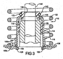
- FIG. 3 which is not part of the invention is a cross-sectianal view of a two-piece valve stem seal assembly illustrating the valve stem seal assembly installed or assembled into an exemplary device, such as an internal combustion engine;
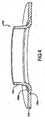
- FIG. 4 is a perspective cross-sectional view of the lower shell of a two-piece valve stem seal assembly as shown in FIG. 3 .
- Example embodiments are provided so that this disclosure will be thorough, and will fully convey the scope to those who are skilled in the art. Numerous specific details are set forth such as examples of specific components, devices, and methods, to provide a thorough understanding of embodiments of the present disclosure. It will be apparent to those skilled in the art that specific details need not be employed, that example embodiments may be embodied in many different forms and that neither should be construed to limit the scope of the disclosure. In some example embodiments, well-known processes, well-known device structures, and well-known technologies are not described in detail.
- first, second, third, etc. may be used herein to describe various elements, components, regions, layers and/or sections, these elements, components, regions, layers and/or sections should not be limed by these terms. These terms may be only used to distinguish one element, component, region, layer or section from another region, layer or section. Terms such as “first.” “second,” and other numerical terms when used herein do not imply a sequence or order unless clearly indicated by the context. Thus, a first element, component, region, layer or section discussed below could be termed a second element, component. region, layer or section without departing from the teachings of the example embodiments.
- spatially relative terms such as “inner,” “outer,” “beneath,” “below,” “lower,” “above,” “upper,” and the like, may be used herein for ease of description to describe one element or feature's relationship to another element(s) or feature(s) as illustrated in the figures.
- Spatially relative terms may be intended to encompass different orientations of the device in use or operation in addition to the orientation depicted in the figures. For example, if the device in the figures is turned over, elements described as “below” or “beneath” other elements or features would then be oriented “above” the other elements or features.
- the example term “below” can encompass both an orientation of above and below.
- the device may be otherwise oriented (rotated 90 degrees or at other orientations) and the spatially relative descriptors used herein interpreted accordingly.
- FIGS. 1 through 2 are primarily directed toward a valve stem seal for an internal combustion engine application.
- FIGS. 3 and 4 show an alternative two-piece valve stem seal assembly. It should be noted, as will become apparent to those skilled in the art from the following description and claims, the principles of the present disclosure are equally applicable to other devices having valves with valve stems thereon.
- a valve stem seal 10 includes a generally rigid cylindrical shell 14, preferably made of a metal-containing material, but which may be made of ceramic or other relatively hard and rigid materials.
- the shell 14 is preferably generally hollow and cylindrical in shape, other shapes may be used depending on the needs of the specific application for the valve stem seal assembly.
- the valve stem seal 10 also includes a resilient sealing member or body 18 that is preferably directly bonded to the rigid cylindrical shell 14.
- the resilient sealing body 18 is preferably made of rubber or a rubber-containing material but may alternately be composed of other resilient elastomers or plastic materials capable of seal in the given environment.
- the resilient sealing body 18 is preferably directly molded to the end wall 20 of the rigid cylindrical shell 14 and may be molded to the end wall 20 such that it completely surrounds the end wall 20.
- other variations may be used for connecting the sealing body 18 to the rigid cylindrical shell 14, such as by an interference fit, adhesives, epoxies or other known connections capable of creating a relatively fixed joint between the cylindrical shell 14 and the resilient sealing body 18.
- a rubber or other resilient elastomeric pad 28 (which can be integral with the sealing body 18) is also molded onto the interior wall of the rigid cylindrical shell 14 and is in contact with the valve guide 24 upon installation in an automotive cylinder head (or engine block assembly portion) 26.
- the resilient sealing body 18 also preferably includes an annular sealing lip 38 at an "upper” or axially outer portion to seal with the valve stem 40 during engine operation.
- the resilient sealing body 18 also includes a concave groove 42 along an upper portion for receiving and retaining a spring member 72 (preferably a garter spring).
- the spring member 72 resiliently urges the resilient annular sealing lip 38 toward its contact with the valve stem 40 during engine operation. This spring member 72 and the annular sealing lip 38 function to control the amount of oil passing between the valve stem 40 and the valve stem seal assembly 10.
- the rigid cylindrical shell 14 also includes a radially outwardly-extending flange or seat 36 adjacent its axially outer or “lower” end which protects the valve spring 32 from wearing against the cylinder head 26 during engine operation.
- one or more grooves 50a, 50b are provided in the flange 36.
- the grooves 50a, 50b can include one or more circumferential grooves 50a disposed on the upper surface of the flange 36 and/or one or more grooves 50b disposed on the lower surface of the flange 36.
- the grooves 50a, 50b can be radially spaced from one another or radially aligned.
- the grooves 50a, 50b permit the flange 36 to flex and lay flat on the engine block to protect the valve stem seal from fatigue.
- the grooves can have a depth of approximately 1 ⁇ 4 to 1 ⁇ 2 material thickness of the flange 36 and can have a rounded, squared, triangular or other shaped cross section.
- the grooves 50a, 50b can be located on the inner half of the flange 36 to allow easier flange flexing.
- the grooves 50a, 50b can be designed with the intent that if fracture does occur, the fracture occurs in a controlled manner along the grooves 50a, 50b. Accordingly, the pattern of the grooves 50a, 50b can be elliptical or other shape to prevent rotation between the flange 36 and the rigid shell 14 in the event of fracture.
- a valve stem seal assembly 110 can have a two-piece construction, including a first generally rigid cylindrical shell 114, preferably made of a metal-containing material, but which may be made of ceramic or other relatively hard and rigid materials.
- first shell 114 is preferably generally hollow and cylindrical in shape, other shapes may be used depending on the needs of the specific application for the valve stem seal assembly.
- the valve stem seal assembly 110 also includes a resilient sealing member or body 118 that is preferably directly bonded to the rigid cylindrical shell 114.
- the inner surface of the first shell 114 engages the exterior surface of a second generally rigid shell 116.
- the second shell 116 is also of a metal-containing material, but which may be made of ceramic or other relatively hard and rigid materials.
- the second shell 116 like the first shell 114, is preferably generally hollow and cylindrical in shape, other shapes may be used depending on the needs of the specific application for the valve stem seal assembly.
- the resilient sealing body 118 is preferably made of rubber or a rubber-containing material but may alternately be composed of other resilient elastomers or plastic materials capable of seal in the given environment.
- the cylindrical shell 114 can have an interference fit with the second cylindrical shell 116.
- connection or bonding may be used, such as welding, direct forging, for example, any other type of bonding or connecting means available.
- the connection between the first and second cylindrical shells can take on the form of the connections disclosed in commonly assigned US Patent Nos. 6,901,902 and 5,775,284 , which are herein incorporated by reference in their entirety.
- the rigid cylindrical shell 114 includes an inwardly extending end wall 120 and an outwardly projecting flange 122 at an inward or "lower" end thereof.
- the resilient sealing body 118 is preferably directly molded to the end wall 120 of the rigid cylindrical shell 114 and may be molded to the end wall 120 such that it completely surrounds the end wall 120.
- other variations may be used for connecting the sealing body 118 to the rigid cylindrical shell 114, such as by an interference fit, adhesives, epoxies or other known connections capable of creating a relatively fixed joint between the cylindrical shell 114 and the resilient sealing body 118.
- a rubber or other resilient elastomeric pad 128 (which can be integral with the sealing body 118) is also molded onto the interior wall of the rigid cylindrical shell 114 and is in contact with the valve guide 124 upon installation in an automotive cylinder head (or engine block assembly portion) 126.
- the preferred interference fit between the first cylindrical shell 114 and the second cylindrical shell 116 creates a retaining force to urge the rubber pad 128 into constant contact with the valve guide assembly 124.
- the resilient sealing body 118 also preferably includes an annular sealing lip 138 at an "upper" or axially outer portion to seal with the valve stem 140 during engine operation.
- the resilient sealing body 118 also includes a concave groove 142 along an upper portion for receiving and retaining a spring member 172 (preferably a garter spring).
- the spring member 172 resiliently urges the resilient annular sealing lip 138 toward its contact with the valve stem 140 during engine operation. This spring member 172 and the annular sealing lip 138 function to control the amount of oil passing between the valve stem 140 and the valve stem seal assembly 110.
- a "vertical" or axially-extending wall 130 of the second cylindrical shell 116 eliminates, or at least substantially minimizes, the possibility of the sealing body 118 of the valve stem assembly 110 separating from the valve guide 124 during operation of the vehicle.
- the axially extending wall 130 of the second cylindrical shell 116 includes a radially inward step 134.
- the second cylindrical shell also includes a radially outwardly-extending flange or seat 136 adjacent its axially outer or “lowar" end. The second shell 116 thus provides a barrier of protection which protects the valve spring 132 from wearing against the cylinder head 126 during engine operation.
- the second cylindrical shell 116 is manufactured separately from the first cylindrical shell 114, thus making it possible to reduce the occurrence of internal stresses in the second cylindrical shell 116. This also allows the second cylindrical shell's flange 36 to have a flatness that can be more accurately controlled, which in tum will reduce the flange bending stress.
- one or more grooves 150a, 150b are provided in the flange 136.
- the grooves 150a, 150b can include on or more circumferential grooves 150a disposed on the upper surface of the flange 136 and/or one or more grooves 150b disposed on the lower surface of the flange 136.
- the grooves 150a, 150b can be radially spaced from one another or radially aligned. In the case of the flange not being manufactured sufficiently flat, the grooves 150a, 150b permit the flange 136 to flex and lay flat on the engine block to protect the valve stem seal from fatigue.
- the grooves 150a, 150b can have a depth of approximately 1 ⁇ 4 to 1 ⁇ 2 the material thickness and can have a rounded, squared, triangular or other shaped cross section.
- the grooves 150a, 150b can be designed with the intent that if fracture does occur, the fracture occurs in a controlled manner along the grooves 150a, 150b. Accordingly, the pattern of grooves 150a, 150b can be elliptical or other shape to prevent rotation between the flange 136 and the rigid shell 116 in the event of fracture.
Landscapes
- Engineering & Computer Science (AREA)
- General Engineering & Computer Science (AREA)
- Mechanical Engineering (AREA)
- Sealing With Elastic Sealing Lips (AREA)
- Check Valves (AREA)
Applications Claiming Priority (1)
| Application Number | Priority Date | Filing Date | Title |
|---|---|---|---|
| US12/512,367 US9416690B2 (en) | 2009-07-30 | 2009-07-30 | Reduced inertia valve stem seal flange |
Publications (2)
| Publication Number | Publication Date |
|---|---|
| EP2295742A1 EP2295742A1 (en) | 2011-03-16 |
| EP2295742B1 true EP2295742B1 (en) | 2014-08-13 |
Family
ID=43332604
Family Applications (1)
| Application Number | Title | Priority Date | Filing Date |
|---|---|---|---|
| EP10006776.8A Not-in-force EP2295742B1 (en) | 2009-07-30 | 2010-06-30 | Reduced inertia valve stem seal flange |
Country Status (6)
| Country | Link |
|---|---|
| US (1) | US9416690B2 (pt) |
| EP (1) | EP2295742B1 (pt) |
| JP (1) | JP5185979B2 (pt) |
| KR (1) | KR101196352B1 (pt) |
| CN (1) | CN101988401B (pt) |
| BR (1) | BRPI1002627A2 (pt) |
Families Citing this family (17)
| Publication number | Priority date | Publication date | Assignee | Title |
|---|---|---|---|---|
| US9500106B2 (en) * | 2009-05-20 | 2016-11-22 | Freudenberg—NOK General Partnership | Two-piece valve stem seal |
| EP3098487B1 (en) * | 2014-01-22 | 2018-06-20 | Nok Corporation | Valve stem seal |
| CN106063298B (zh) * | 2014-03-05 | 2019-07-12 | 华为技术有限公司 | 用于自定义的第五代网络的系统与方法 |
| JP6628205B2 (ja) * | 2015-07-15 | 2020-01-08 | Nok株式会社 | バルブステムシール |
| WO2017030060A1 (ja) * | 2015-08-20 | 2017-02-23 | Nok株式会社 | バルブステムシール及び密封構造 |
| DE102017202585A1 (de) * | 2016-02-17 | 2017-08-17 | Mahle International Gmbh | Brennkraftmaschine mit zumindest einem Zylinder und mit zumindest zwei Hohlkopfventilen |
| ITUA20162719A1 (it) * | 2016-04-19 | 2017-10-19 | Freudenberg Sealing Tech S A S Di Externa Italia S R L U | Guarnizione per una valvola di un motore a combustione interna |
| KR101839866B1 (ko) | 2016-09-29 | 2018-03-19 | 평화오일씰공업 주식회사 | 밸브 스템 씰 |
| JP7034753B2 (ja) * | 2018-02-19 | 2022-03-14 | Nok株式会社 | 密封装置および密封構造 |
| CN108443554A (zh) * | 2018-03-27 | 2018-08-24 | 浙江佳乐科仪股份有限公司 | 一种阀门操作机械手 |
| US10746062B2 (en) * | 2018-04-04 | 2020-08-18 | Freudenberg Sealing Technologies S.A.S. Di Externa Italia S.R.L.U. | Gasket with an improved heat dissipation capacity for a valve of an internal combustion engine |
| CN113167387A (zh) | 2019-03-20 | 2021-07-23 | Nok株式会社 | 密封装置 |
| JP7344696B2 (ja) * | 2019-07-25 | 2023-09-14 | Nok株式会社 | 密封構造 |
| KR102251417B1 (ko) | 2020-03-11 | 2021-05-12 | 평화오일씰공업 주식회사 | 밸브 스템 씰 및 이를 구비한 내연기관 밸브 |
| CN114746678A (zh) * | 2020-04-28 | 2022-07-12 | Nok株式会社 | 阀杆密封件 |
| CN113944527B (zh) * | 2020-07-16 | 2024-12-27 | 烟台坤正密封制品有限公司 | 一种泄漏量可调节气门油封 |
| DE102021207916A1 (de) * | 2021-07-23 | 2023-01-26 | Aktiebolaget Skf | Ventilschaftdichtung |
Family Cites Families (18)
| Publication number | Priority date | Publication date | Assignee | Title |
|---|---|---|---|---|
| US3554562A (en) * | 1967-06-21 | 1971-01-12 | Gen Motors Corp | Valve stem seal assembly |
| DE1750200A1 (de) | 1968-04-06 | 1971-02-11 | Alois Ferch | Mehrteilige Ventilschaftabdichtung fuer Brennkraftmaschinen od.dgl. |
| US3554180A (en) * | 1969-03-21 | 1971-01-12 | Gen Motors Corp | Valve stem seal |
| US4717178A (en) * | 1986-06-03 | 1988-01-05 | Mueller Co. | Frangible coupling for barrel sections of a fire hydrant |
| GB8629408D0 (en) * | 1986-12-09 | 1987-01-21 | Ford Motor Co | Valve assembly |
| DE3902518A1 (de) * | 1989-01-28 | 1990-08-02 | Goetze Ag | Ventilschaftabdichtung |
| US4947811A (en) * | 1989-06-30 | 1990-08-14 | Dana Corporation | Floating valve stem seal |
| US4909202A (en) * | 1989-06-30 | 1990-03-20 | Dana Corporation | Frustoconical valve stem sealing element |
| US5174256A (en) * | 1991-11-25 | 1992-12-29 | Dana Corporation | Variable guide height valve seal |
| DE4403510C2 (de) * | 1994-02-04 | 1995-11-30 | Bruss Dichtungstechnik | Ventilmodul für Brennkraftmaschinen und Verfahren zu dessen Einbau |
| US5558056A (en) * | 1995-11-14 | 1996-09-24 | Freudenberg-Nok General Partnership | Two-piece valve stem seal |
| US5775284A (en) * | 1997-05-07 | 1998-07-07 | Freudenberg-Nok General Partnership | Two-piece valve stem seal |
| US6848671B2 (en) * | 2001-11-29 | 2005-02-01 | Dana Corporation | Valve spring anti-rotation apparatus |
| DE10207382C1 (de) | 2002-02-21 | 2003-05-15 | Freudenberg Carl Kg | Ventilschaftdichtung für eine Brennkraftmaschine |
| DE10325764B3 (de) * | 2003-06-05 | 2005-08-04 | Carl Freudenberg Kg | Ventilschaftabdichtung für Brennkraftmaschinen |
| US6901902B1 (en) * | 2004-02-25 | 2005-06-07 | Freudenberg-Nok General Partnership | Two-piece valve stem seal |
| US7316386B2 (en) * | 2005-06-09 | 2008-01-08 | Dana Corporation | Valve stem seal assembly |
| US9500106B2 (en) * | 2009-05-20 | 2016-11-22 | Freudenberg—NOK General Partnership | Two-piece valve stem seal |
-
2009
- 2009-07-30 US US12/512,367 patent/US9416690B2/en not_active Expired - Fee Related
-
2010
- 2010-06-30 EP EP10006776.8A patent/EP2295742B1/en not_active Not-in-force
- 2010-07-28 KR KR1020100072829A patent/KR101196352B1/ko not_active Expired - Fee Related
- 2010-07-28 JP JP2010169155A patent/JP5185979B2/ja not_active Expired - Fee Related
- 2010-07-29 BR BRPI1002627-4A patent/BRPI1002627A2/pt not_active Application Discontinuation
- 2010-07-30 CN CN201010243540.4A patent/CN101988401B/zh not_active Expired - Fee Related
Also Published As
| Publication number | Publication date |
|---|---|
| US20110024666A1 (en) | 2011-02-03 |
| JP2011033187A (ja) | 2011-02-17 |
| CN101988401B (zh) | 2015-09-09 |
| BRPI1002627A2 (pt) | 2012-03-27 |
| JP5185979B2 (ja) | 2013-04-17 |
| EP2295742A1 (en) | 2011-03-16 |
| KR101196352B1 (ko) | 2012-11-01 |
| US9416690B2 (en) | 2016-08-16 |
| CN101988401A (zh) | 2011-03-23 |
| KR20110013281A (ko) | 2011-02-09 |
Similar Documents
| Publication | Publication Date | Title |
|---|---|---|
| EP2295742B1 (en) | Reduced inertia valve stem seal flange | |
| USRE40764E1 (en) | Two-piece valve stem seal | |
| US5775284A (en) | Two-piece valve stem seal | |
| US5558056A (en) | Two-piece valve stem seal | |
| US5553869A (en) | Bonded valve stem seal with retainer tangs | |
| CA2836807C (en) | Eccentricity tolerant valve stem seal assembly | |
| US20110241296A1 (en) | Energy Saving Seal With Main Lip And Dust Lip Hinge Point | |
| CN105190084B (zh) | 用于封闭振动阻尼器的阻尼管的包封件 | |
| EP2253809A1 (en) | Two-piece valve stem seal | |
| KR20130038240A (ko) | 개선된 시일 요소 접착 이음매를 가지는 저 토크 샤프트 시일 | |
| US11629784B2 (en) | Sealing ring and use thereof | |
| US9746081B2 (en) | Low load offset seal | |
| CN103423457A (zh) | 具有外直径片状物的低负荷密封件 | |
| US20170284477A1 (en) | Connector arrangement for centering two shaft sections to be connected with one another | |
| EP2964912B1 (en) | Pressure support for engine valve stem seals | |
| AU2022201961B2 (en) | Valve Stem Seal Structure | |
| JP7303293B2 (ja) | バルブステムシール | |
| JPS5865372A (ja) | リツプシ−ルリング | |
| JP2019044898A (ja) | バルブステムシール | |
| US20130032118A1 (en) | Low Profile Valve Stem Seal In Cylinder Head |
Legal Events
| Date | Code | Title | Description |
|---|---|---|---|
| PUAI | Public reference made under article 153(3) epc to a published international application that has entered the european phase |
Free format text: ORIGINAL CODE: 0009012 |
|
| AK | Designated contracting states |
Kind code of ref document: A1 Designated state(s): AL AT BE BG CH CY CZ DE DK EE ES FI FR GB GR HR HU IE IS IT LI LT LU LV MC MK MT NL NO PL PT RO SE SI SK SM TR |
|
| AX | Request for extension of the european patent |
Extension state: BA ME RS |
|
| 17P | Request for examination filed |
Effective date: 20110912 |
|
| 17Q | First examination report despatched |
Effective date: 20121120 |
|
| GRAP | Despatch of communication of intention to grant a patent |
Free format text: ORIGINAL CODE: EPIDOSNIGR1 |
|
| GRAJ | Information related to disapproval of communication of intention to grant by the applicant or resumption of examination proceedings by the epo deleted |
Free format text: ORIGINAL CODE: EPIDOSDIGR1 |
|
| GRAP | Despatch of communication of intention to grant a patent |
Free format text: ORIGINAL CODE: EPIDOSNIGR1 |
|
| INTG | Intention to grant announced |
Effective date: 20140401 |
|
| INTC | Intention to grant announced (deleted) | ||
| INTG | Intention to grant announced |
Effective date: 20140414 |
|
| GRAS | Grant fee paid |
Free format text: ORIGINAL CODE: EPIDOSNIGR3 |
|
| GRAA | (expected) grant |
Free format text: ORIGINAL CODE: 0009210 |
|
| AK | Designated contracting states |
Kind code of ref document: B1 Designated state(s): AL AT BE BG CH CY CZ DE DK EE ES FI FR GB GR HR HU IE IS IT LI LT LU LV MC MK MT NL NO PL PT RO SE SI SK SM TR |
|
| REG | Reference to a national code |
Ref country code: GB Ref legal event code: FG4D |
|
| REG | Reference to a national code |
Ref country code: CH Ref legal event code: EP Ref country code: AT Ref legal event code: REF Ref document number: 682403 Country of ref document: AT Kind code of ref document: T Effective date: 20140815 |
|
| REG | Reference to a national code |
Ref country code: IE Ref legal event code: FG4D |
|
| REG | Reference to a national code |
Ref country code: DE Ref legal event code: R096 Ref document number: 602010018144 Country of ref document: DE Effective date: 20140925 |
|
| REG | Reference to a national code |
Ref country code: NL Ref legal event code: VDEP Effective date: 20140813 |
|
| REG | Reference to a national code |
Ref country code: AT Ref legal event code: MK05 Ref document number: 682403 Country of ref document: AT Kind code of ref document: T Effective date: 20140813 |
|
| REG | Reference to a national code |
Ref country code: LT Ref legal event code: MG4D |
|
| PG25 | Lapsed in a contracting state [announced via postgrant information from national office to epo] |
Ref country code: GR Free format text: LAPSE BECAUSE OF FAILURE TO SUBMIT A TRANSLATION OF THE DESCRIPTION OR TO PAY THE FEE WITHIN THE PRESCRIBED TIME-LIMIT Effective date: 20141114 Ref country code: NO Free format text: LAPSE BECAUSE OF FAILURE TO SUBMIT A TRANSLATION OF THE DESCRIPTION OR TO PAY THE FEE WITHIN THE PRESCRIBED TIME-LIMIT Effective date: 20141113 Ref country code: BG Free format text: LAPSE BECAUSE OF FAILURE TO SUBMIT A TRANSLATION OF THE DESCRIPTION OR TO PAY THE FEE WITHIN THE PRESCRIBED TIME-LIMIT Effective date: 20141113 Ref country code: PT Free format text: LAPSE BECAUSE OF FAILURE TO SUBMIT A TRANSLATION OF THE DESCRIPTION OR TO PAY THE FEE WITHIN THE PRESCRIBED TIME-LIMIT Effective date: 20141215 Ref country code: FI Free format text: LAPSE BECAUSE OF FAILURE TO SUBMIT A TRANSLATION OF THE DESCRIPTION OR TO PAY THE FEE WITHIN THE PRESCRIBED TIME-LIMIT Effective date: 20140813 Ref country code: LT Free format text: LAPSE BECAUSE OF FAILURE TO SUBMIT A TRANSLATION OF THE DESCRIPTION OR TO PAY THE FEE WITHIN THE PRESCRIBED TIME-LIMIT Effective date: 20140813 Ref country code: ES Free format text: LAPSE BECAUSE OF FAILURE TO SUBMIT A TRANSLATION OF THE DESCRIPTION OR TO PAY THE FEE WITHIN THE PRESCRIBED TIME-LIMIT Effective date: 20140813 Ref country code: SE Free format text: LAPSE BECAUSE OF FAILURE TO SUBMIT A TRANSLATION OF THE DESCRIPTION OR TO PAY THE FEE WITHIN THE PRESCRIBED TIME-LIMIT Effective date: 20140813 |
|
| PG25 | Lapsed in a contracting state [announced via postgrant information from national office to epo] |
Ref country code: LV Free format text: LAPSE BECAUSE OF FAILURE TO SUBMIT A TRANSLATION OF THE DESCRIPTION OR TO PAY THE FEE WITHIN THE PRESCRIBED TIME-LIMIT Effective date: 20140813 Ref country code: CY Free format text: LAPSE BECAUSE OF FAILURE TO SUBMIT A TRANSLATION OF THE DESCRIPTION OR TO PAY THE FEE WITHIN THE PRESCRIBED TIME-LIMIT Effective date: 20140813 Ref country code: AT Free format text: LAPSE BECAUSE OF FAILURE TO SUBMIT A TRANSLATION OF THE DESCRIPTION OR TO PAY THE FEE WITHIN THE PRESCRIBED TIME-LIMIT Effective date: 20140813 Ref country code: IS Free format text: LAPSE BECAUSE OF FAILURE TO SUBMIT A TRANSLATION OF THE DESCRIPTION OR TO PAY THE FEE WITHIN THE PRESCRIBED TIME-LIMIT Effective date: 20141213 Ref country code: HR Free format text: LAPSE BECAUSE OF FAILURE TO SUBMIT A TRANSLATION OF THE DESCRIPTION OR TO PAY THE FEE WITHIN THE PRESCRIBED TIME-LIMIT Effective date: 20140813 |
|
| PG25 | Lapsed in a contracting state [announced via postgrant information from national office to epo] |
Ref country code: NL Free format text: LAPSE BECAUSE OF FAILURE TO SUBMIT A TRANSLATION OF THE DESCRIPTION OR TO PAY THE FEE WITHIN THE PRESCRIBED TIME-LIMIT Effective date: 20140813 |
|
| PG25 | Lapsed in a contracting state [announced via postgrant information from national office to epo] |
Ref country code: DK Free format text: LAPSE BECAUSE OF FAILURE TO SUBMIT A TRANSLATION OF THE DESCRIPTION OR TO PAY THE FEE WITHIN THE PRESCRIBED TIME-LIMIT Effective date: 20140813 Ref country code: SK Free format text: LAPSE BECAUSE OF FAILURE TO SUBMIT A TRANSLATION OF THE DESCRIPTION OR TO PAY THE FEE WITHIN THE PRESCRIBED TIME-LIMIT Effective date: 20140813 Ref country code: EE Free format text: LAPSE BECAUSE OF FAILURE TO SUBMIT A TRANSLATION OF THE DESCRIPTION OR TO PAY THE FEE WITHIN THE PRESCRIBED TIME-LIMIT Effective date: 20140813 Ref country code: CZ Free format text: LAPSE BECAUSE OF FAILURE TO SUBMIT A TRANSLATION OF THE DESCRIPTION OR TO PAY THE FEE WITHIN THE PRESCRIBED TIME-LIMIT Effective date: 20140813 Ref country code: RO Free format text: LAPSE BECAUSE OF FAILURE TO SUBMIT A TRANSLATION OF THE DESCRIPTION OR TO PAY THE FEE WITHIN THE PRESCRIBED TIME-LIMIT Effective date: 20140813 |
|
| REG | Reference to a national code |
Ref country code: DE Ref legal event code: R097 Ref document number: 602010018144 Country of ref document: DE |
|
| PG25 | Lapsed in a contracting state [announced via postgrant information from national office to epo] |
Ref country code: PL Free format text: LAPSE BECAUSE OF FAILURE TO SUBMIT A TRANSLATION OF THE DESCRIPTION OR TO PAY THE FEE WITHIN THE PRESCRIBED TIME-LIMIT Effective date: 20140813 |
|
| PLBE | No opposition filed within time limit |
Free format text: ORIGINAL CODE: 0009261 |
|
| STAA | Information on the status of an ep patent application or granted ep patent |
Free format text: STATUS: NO OPPOSITION FILED WITHIN TIME LIMIT |
|
| REG | Reference to a national code |
Ref country code: FR Ref legal event code: PLFP Year of fee payment: 6 |
|
| 26N | No opposition filed |
Effective date: 20150515 |
|
| PG25 | Lapsed in a contracting state [announced via postgrant information from national office to epo] |
Ref country code: SI Free format text: LAPSE BECAUSE OF FAILURE TO SUBMIT A TRANSLATION OF THE DESCRIPTION OR TO PAY THE FEE WITHIN THE PRESCRIBED TIME-LIMIT Effective date: 20140813 |
|
| PG25 | Lapsed in a contracting state [announced via postgrant information from national office to epo] |
Ref country code: MC Free format text: LAPSE BECAUSE OF FAILURE TO SUBMIT A TRANSLATION OF THE DESCRIPTION OR TO PAY THE FEE WITHIN THE PRESCRIBED TIME-LIMIT Effective date: 20140813 |
|
| REG | Reference to a national code |
Ref country code: CH Ref legal event code: PL |
|
| PG25 | Lapsed in a contracting state [announced via postgrant information from national office to epo] |
Ref country code: LU Free format text: LAPSE BECAUSE OF FAILURE TO SUBMIT A TRANSLATION OF THE DESCRIPTION OR TO PAY THE FEE WITHIN THE PRESCRIBED TIME-LIMIT Effective date: 20150630 |
|
| REG | Reference to a national code |
Ref country code: IE Ref legal event code: MM4A |
|
| PG25 | Lapsed in a contracting state [announced via postgrant information from national office to epo] |
Ref country code: CH Free format text: LAPSE BECAUSE OF NON-PAYMENT OF DUE FEES Effective date: 20150630 Ref country code: LI Free format text: LAPSE BECAUSE OF NON-PAYMENT OF DUE FEES Effective date: 20150630 Ref country code: IE Free format text: LAPSE BECAUSE OF NON-PAYMENT OF DUE FEES Effective date: 20150630 |
|
| REG | Reference to a national code |
Ref country code: FR Ref legal event code: PLFP Year of fee payment: 7 |
|
| PG25 | Lapsed in a contracting state [announced via postgrant information from national office to epo] |
Ref country code: BE Free format text: LAPSE BECAUSE OF FAILURE TO SUBMIT A TRANSLATION OF THE DESCRIPTION OR TO PAY THE FEE WITHIN THE PRESCRIBED TIME-LIMIT Effective date: 20140813 |
|
| PG25 | Lapsed in a contracting state [announced via postgrant information from national office to epo] |
Ref country code: MT Free format text: LAPSE BECAUSE OF FAILURE TO SUBMIT A TRANSLATION OF THE DESCRIPTION OR TO PAY THE FEE WITHIN THE PRESCRIBED TIME-LIMIT Effective date: 20140813 |
|
| PG25 | Lapsed in a contracting state [announced via postgrant information from national office to epo] |
Ref country code: SM Free format text: LAPSE BECAUSE OF FAILURE TO SUBMIT A TRANSLATION OF THE DESCRIPTION OR TO PAY THE FEE WITHIN THE PRESCRIBED TIME-LIMIT Effective date: 20140813 Ref country code: HU Free format text: LAPSE BECAUSE OF FAILURE TO SUBMIT A TRANSLATION OF THE DESCRIPTION OR TO PAY THE FEE WITHIN THE PRESCRIBED TIME-LIMIT; INVALID AB INITIO Effective date: 20100630 |
|
| REG | Reference to a national code |
Ref country code: FR Ref legal event code: PLFP Year of fee payment: 8 |
|
| PG25 | Lapsed in a contracting state [announced via postgrant information from national office to epo] |
Ref country code: TR Free format text: LAPSE BECAUSE OF FAILURE TO SUBMIT A TRANSLATION OF THE DESCRIPTION OR TO PAY THE FEE WITHIN THE PRESCRIBED TIME-LIMIT Effective date: 20140813 |
|
| REG | Reference to a national code |
Ref country code: FR Ref legal event code: PLFP Year of fee payment: 9 |
|
| PG25 | Lapsed in a contracting state [announced via postgrant information from national office to epo] |
Ref country code: MK Free format text: LAPSE BECAUSE OF FAILURE TO SUBMIT A TRANSLATION OF THE DESCRIPTION OR TO PAY THE FEE WITHIN THE PRESCRIBED TIME-LIMIT Effective date: 20140813 |
|
| PG25 | Lapsed in a contracting state [announced via postgrant information from national office to epo] |
Ref country code: AL Free format text: LAPSE BECAUSE OF FAILURE TO SUBMIT A TRANSLATION OF THE DESCRIPTION OR TO PAY THE FEE WITHIN THE PRESCRIBED TIME-LIMIT Effective date: 20140813 |
|
| PGFP | Annual fee paid to national office [announced via postgrant information from national office to epo] |
Ref country code: GB Payment date: 20220625 Year of fee payment: 13 |
|
| PGFP | Annual fee paid to national office [announced via postgrant information from national office to epo] |
Ref country code: FR Payment date: 20220625 Year of fee payment: 13 |
|
| PGFP | Annual fee paid to national office [announced via postgrant information from national office to epo] |
Ref country code: IT Payment date: 20220630 Year of fee payment: 13 Ref country code: DE Payment date: 20220628 Year of fee payment: 13 |
|
| REG | Reference to a national code |
Ref country code: DE Ref legal event code: R119 Ref document number: 602010018144 Country of ref document: DE |
|
| GBPC | Gb: european patent ceased through non-payment of renewal fee |
Effective date: 20230630 |
|
| PG25 | Lapsed in a contracting state [announced via postgrant information from national office to epo] |
Ref country code: DE Free format text: LAPSE BECAUSE OF NON-PAYMENT OF DUE FEES Effective date: 20240103 Ref country code: GB Free format text: LAPSE BECAUSE OF NON-PAYMENT OF DUE FEES Effective date: 20230630 |
|
| PG25 | Lapsed in a contracting state [announced via postgrant information from national office to epo] |
Ref country code: FR Free format text: LAPSE BECAUSE OF NON-PAYMENT OF DUE FEES Effective date: 20230630 |
|
| PG25 | Lapsed in a contracting state [announced via postgrant information from national office to epo] |
Ref country code: IT Free format text: LAPSE BECAUSE OF NON-PAYMENT OF DUE FEES Effective date: 20230630 |