EP2295847A2 - Luminaire, en particulier luminaire de tunnel - Google Patents
Luminaire, en particulier luminaire de tunnel Download PDFInfo
- Publication number
- EP2295847A2 EP2295847A2 EP10009533A EP10009533A EP2295847A2 EP 2295847 A2 EP2295847 A2 EP 2295847A2 EP 10009533 A EP10009533 A EP 10009533A EP 10009533 A EP10009533 A EP 10009533A EP 2295847 A2 EP2295847 A2 EP 2295847A2
- Authority
- EP
- European Patent Office
- Prior art keywords
- luminaire
- module
- lamp
- housing
- plate
- Prior art date
- Legal status (The legal status is an assumption and is not a legal conclusion. Google has not performed a legal analysis and makes no representation as to the accuracy of the status listed.)
- Withdrawn
Links
- 238000000034 method Methods 0.000 claims description 7
- 239000000853 adhesive Substances 0.000 claims description 4
- 230000001070 adhesive effect Effects 0.000 claims description 4
- 238000005286 illumination Methods 0.000 description 7
- 238000001816 cooling Methods 0.000 description 5
- 239000002313 adhesive film Substances 0.000 description 3
- 229910052782 aluminium Inorganic materials 0.000 description 3
- XAGFODPZIPBFFR-UHFFFAOYSA-N aluminium Chemical compound [Al] XAGFODPZIPBFFR-UHFFFAOYSA-N 0.000 description 3
- 238000013461 design Methods 0.000 description 3
- 238000012423 maintenance Methods 0.000 description 3
- 229910052751 metal Inorganic materials 0.000 description 3
- 239000002184 metal Substances 0.000 description 3
- 229920003023 plastic Polymers 0.000 description 3
- 238000012546 transfer Methods 0.000 description 3
- 239000004020 conductor Substances 0.000 description 2
- 239000011521 glass Substances 0.000 description 2
- 230000017525 heat dissipation Effects 0.000 description 2
- 229910000831 Steel Inorganic materials 0.000 description 1
- 230000001154 acute effect Effects 0.000 description 1
- 150000001875 compounds Chemical class 0.000 description 1
- 238000011161 development Methods 0.000 description 1
- 230000018109 developmental process Effects 0.000 description 1
- 238000005265 energy consumption Methods 0.000 description 1
- 238000005516 engineering process Methods 0.000 description 1
- 230000002349 favourable effect Effects 0.000 description 1
- 230000004313 glare Effects 0.000 description 1
- 239000003365 glass fiber Substances 0.000 description 1
- 238000009434 installation Methods 0.000 description 1
- 238000009413 insulation Methods 0.000 description 1
- 239000000463 material Substances 0.000 description 1
- 229910001507 metal halide Inorganic materials 0.000 description 1
- 150000005309 metal halides Chemical class 0.000 description 1
- 238000012986 modification Methods 0.000 description 1
- 230000004048 modification Effects 0.000 description 1
- 239000007787 solid Substances 0.000 description 1
- 229910001220 stainless steel Inorganic materials 0.000 description 1
- 239000010935 stainless steel Substances 0.000 description 1
- 239000010959 steel Substances 0.000 description 1
- 238000012549 training Methods 0.000 description 1
- 239000012780 transparent material Substances 0.000 description 1
Images


Classifications
-
- F—MECHANICAL ENGINEERING; LIGHTING; HEATING; WEAPONS; BLASTING
- F21—LIGHTING
- F21V—FUNCTIONAL FEATURES OR DETAILS OF LIGHTING DEVICES OR SYSTEMS THEREOF; STRUCTURAL COMBINATIONS OF LIGHTING DEVICES WITH OTHER ARTICLES, NOT OTHERWISE PROVIDED FOR
- F21V29/00—Protecting lighting devices from thermal damage; Cooling or heating arrangements specially adapted for lighting devices or systems
- F21V29/50—Cooling arrangements
- F21V29/70—Cooling arrangements characterised by passive heat-dissipating elements, e.g. heat-sinks
- F21V29/74—Cooling arrangements characterised by passive heat-dissipating elements, e.g. heat-sinks with fins or blades
-
- F—MECHANICAL ENGINEERING; LIGHTING; HEATING; WEAPONS; BLASTING
- F21—LIGHTING
- F21V—FUNCTIONAL FEATURES OR DETAILS OF LIGHTING DEVICES OR SYSTEMS THEREOF; STRUCTURAL COMBINATIONS OF LIGHTING DEVICES WITH OTHER ARTICLES, NOT OTHERWISE PROVIDED FOR
- F21V29/00—Protecting lighting devices from thermal damage; Cooling or heating arrangements specially adapted for lighting devices or systems
- F21V29/50—Cooling arrangements
- F21V29/70—Cooling arrangements characterised by passive heat-dissipating elements, e.g. heat-sinks
-
- F—MECHANICAL ENGINEERING; LIGHTING; HEATING; WEAPONS; BLASTING
- F21—LIGHTING
- F21S—NON-PORTABLE LIGHTING DEVICES; SYSTEMS THEREOF; VEHICLE LIGHTING DEVICES SPECIALLY ADAPTED FOR VEHICLE EXTERIORS
- F21S4/00—Lighting devices or systems using a string or strip of light sources
- F21S4/20—Lighting devices or systems using a string or strip of light sources with light sources held by or within elongate supports
-
- F—MECHANICAL ENGINEERING; LIGHTING; HEATING; WEAPONS; BLASTING
- F21—LIGHTING
- F21W—INDEXING SCHEME ASSOCIATED WITH SUBCLASSES F21K, F21L, F21S and F21V, RELATING TO USES OR APPLICATIONS OF LIGHTING DEVICES OR SYSTEMS
- F21W2131/00—Use or application of lighting devices or systems not provided for in codes F21W2102/00-F21W2121/00
- F21W2131/10—Outdoor lighting
- F21W2131/101—Outdoor lighting of tunnels or the like, e.g. under bridges
-
- F—MECHANICAL ENGINEERING; LIGHTING; HEATING; WEAPONS; BLASTING
- F21—LIGHTING
- F21Y—INDEXING SCHEME ASSOCIATED WITH SUBCLASSES F21K, F21L, F21S and F21V, RELATING TO THE FORM OR THE KIND OF THE LIGHT SOURCES OR OF THE COLOUR OF THE LIGHT EMITTED
- F21Y2115/00—Light-generating elements of semiconductor light sources
- F21Y2115/10—Light-emitting diodes [LED]
Definitions
- the invention relates to a luminaire, in particular a tunnel luminaire according to the preamble of claim 1.
- luminaire for indoor and outdoor operation, in particular for the illumination of tunnels, are well known.
- the term luminaire is here understood to mean a lighting device with at least one lamp (illuminant) and other technical components such as, for example, a luminaire housing, electrical cables, fastening elements, etc.
- Such a lamp When used as a tunnel light such a lamp is usually placed on the tunnel ceiling. To illuminate the single or multi-lane tunnel roadway, several such tunnel lights are preferably provided in series along the tunnel roadway to be illuminated.
- the disadvantage arises when using conventional light sources such as metal halide lamps or the like light an inhomogeneous illumination of the road.
- the present invention seeks to provide a lamp, in particular tunnel lamp with a plurality of bulbs formed by light emitting diodes, which ensures a uniform and reliable illumination of the tunnel carriageway with low maintenance.
- the task becomes starting from the features of the preamble of claim 1 solved by its characterizing features.
- the essential aspect of the tunnel luminaire according to the invention is the fact that at least one multi-part luminaire module is accommodated in the luminaire housing, which is mounted exchangeable and thermally conductive via at least one retaining profile, wherein the at least one retaining profile is thermally conductively connected to the luminaire housing.
- the at least one retaining profile is thermally conductively connected to the luminaire housing.
- the lamp module is designed as a plug-in module and forms a self-sufficient, interchangeable module.
- a plug-in module By combining several light sources formed by LEDs and the components required for its control in a self-sufficient, interchangeable module forming module and a change of the light source during operation is possible.
- the training as a plug-in module also results in a particularly user-friendly operation or maintenance of the lamp, in particular tunnel lamp.
- the luminaire module preferably has at least one plug connection and the associated holding profile at least one further plug connection for producing a plug connection.
- At least one retaining profile is provided, which is thermally conductively connected in the lamp housing.
- the luminaire module also has at least one elongated and / or plate-shaped carrier body, which can be thermally conductively connected to the at least one holding profile, preferably by means of a plug connection.
- the luminaire module can have at least one control unit and at least one power supply unit.
- a supply module for receiving at least one control unit and at least one power supply unit in the luminaire housing can also be provided interchangeably.
- the light-emitting diodes are advantageously arranged on at least one printed circuit board, which is thermally conductively connected to the upper side of the elongate and / or plate-shaped carrier body, preferably by means of thermally conductive adhesives, specifically the light emitting diodes are preferably along the longitudinal axis of the elongated and / or plate-shaped carrier body the at least one printed circuit board provided.
- the elongated and / or plate-shaped carrier body may have in an advantageous embodiment at the top at least one elongated, in cross-section U- or V-shaped recess for receiving the light-emitting diode comprising printed circuit board, which at least partially forms a reflector.
- the elongated and / or plate-shaped carrier body may be formed by a carrier plate, on whose upper side a reflector attachment module is provided.
- the invention furthermore relates to a method for controlling at least one luminaire, in particular a tunnel luminaire having at least two luminaire modules, in which the at least two luminaire plug-in modules are controlled separately from one another via a central control unit and operated at different time intervals.
- at least one luminaire module can be operated in a first time interval and at least one further luminaire module in a second time interval, the first and second time intervals being different from one another. It is also possible to dim the lighting modules via the central control unit.
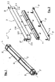
- FIGS 1 - 4 and 10 are each exemplified different views of a lamp 1, which essentially consists of a preferably elongated luminaire housing 2 and a cover 3 formed at least partially transparent.
- Such a luminaire 1 is used, for example, to illuminate a tunnel and is attached thereto for this purpose on the tunnel ceiling or on the side walls of the tunnel.
- a plurality of "tunnel lights" 1 connected in parallel or in series with one another may be provided in a tunnel, which are connected and / or controlled jointly or in groups via a central control unit, not shown in the figures.
- the luminaire housing 2 is made of metal, in particular steel or stainless steel, for example.
- the luminaire housing 2 forms, together with the cover 3, a splash-proof installation space for accommodating the luminous means in the form of light-emitting diodes or so-called LEDs 13 and further components of the luminaire 1.
- the luminaire housing 2 has unspecified lead-through openings, which are likewise formed moisture-tight.
- the cover 3 is preferably made of a transparent material, for example glass or a transparent plastic material, which is fastened to the light housing 2 via a plurality of fastening devices 3 '.
- the cover 3 may for example be constructed in several parts and consist of a frame member with circumferential seal and at least one transparent component, preferably a glass plate or a transparent plastic plate.
- brackets 2 ', 2 " For rotatably mounting the lamp 1, preferably to their longitudinal axis L on the tunnel ceiling or a tunnel side wall are also at least two brackets 2 ', 2 "provided, which are arranged for example at the free ends of the tunnel lamp 1.
- the luminaire housing 2 is preferably of cuboid design and has an upper side 2.1, a first and a second transverse side 2.2, 2.3, a first and a second longitudinal side 2.4, 2.5 and an underside 2.6 opposite the upper side 2.1.
- the top 2.1 is formed open and closed by means of the cover 3 preferably splash-proof.
- the interior space enclosed by the luminaire housing 2 is designed to accommodate at least one luminaire module 4 according to the invention and at least one retaining profile 5 provided for its mounting.
- the lighting module 4 is realized in the form of a plug-in module, which forms a self-contained, interchangeable module that can be replaced quickly and easily in case of failure or for maintenance purposes.
- a first to third luminaire module 4, 4 ', 4 " provided in a lamp 1, wherein for fixing a light module 4, 4', 4" in each case a holding profile 5, 5 ', 5 "is provided.
- the first to third luminaire modules 4, 4 ', 4 each form an autonomously operable assembly, which are mounted on a respective one or more part holding profile 5 arranged on the underside 1.6 opposite the inside of the luminaire housing 2
- each lamp module 4, 4 ', 4 associated with a holding profile 5, 5', 5", which are arranged as separate components in the light housing 2, preferably along the lamp longitudinal axis L.
- a common holding profile 5 for several lighting modules 4, 4 ', 4 be provided.
- FIG. 10 an alternative embodiment shown in which a first and second lamp module 4, 4 'are provided, which are interchangeable with a first and second retaining section 5, 5' connected to the lamp housing, in each case lamp module 4, 4 'with two holding profiles 5, 5 '.
- the respective luminaire module 4, 4 ', 4 can be connected, for example, via a plug connection with the associated holding profile 5, 5', 5" or the common holding profile 5, 5 '.
- the lighting modules 4, 4 ' by means of a screw on the support section 5, 5' be releasably secured.
- the holding profile 5 is preferably made of a thermally conductive material, preferably metal or aluminum.
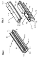
- the luminaire module 4, 4 ', 4 has at least one elongate and / or plate-shaped carrier body 6 and at least one printed circuit board 10 with a plurality of light-emitting diodes 13 which form the luminous means of the respective luminaire module 4, 4', 4".
- the luminous module 4, 4 ', 4 "additionally comprises at least one control unit 7, at least one power supply unit 8 and at least one plug connection 9.
- the elongate and / or plate-shaped support body 6 has an upper side 6.1 and a lower side 6.2, wherein at the top 6.1
- the control unit 7, the power supply unit 8 and the plug-in connection 9 are preferably arranged on the underside 6.2 of the elongated support body 6.
- the elongated and / or plate-shaped support body 6 is made of a thermally conductive material, preferably metal or aluminum, for example, this may be formed by a solid aluminum die-cast body.
- At least one elongated, in cross-section U- or V-shaped recess 11 is provided, for example, on the upper side 6.1 of the elongate support body 6, which is preferably formed symmetrically to the longitudinal axis LA.
- the recess 11 in this case forms, at least in sections, a reflector, via which the light generated by the light-emitting diodes 13 is suitably reflected and scattered. As a result, a uniform illumination of a tunnel can be achieved.
- the at least one retaining profile 5, 5 ', 5 "and the elongate and / or plate-shaped support body 6 of the respective luminaire module 4, 4', 4" in this case form a two-part cooling arrangement, wherein the at least one retaining profile 5, 5 ', 5 "a
- the holding profile 5, 5 ', 5 "realized, for example, as a U-shaped or C-shaped profile element, the two opposing Leg 5.1, 5.2 interconnecting holding section 5.3 is thermally conductively connected to the lamp housing 2.
- the free ends of the two opposite legs 5.1, 5.2 in this case point in the direction of the upper side 1.1 of the luminaire housing 2 and are thermally conductively connected to the elongate and / or plate-shaped carrier body 6.
- the elongated and / or plate-shaped carrier body 6 preferably has lateral grooves 6 ', 6 "running parallel to the longitudinal axis LA on the underside 6.2, into which the free ends of the legs 5.1, 5.2 of the lower heat sink or holding profile 5 engage
- the thermal energy generated by the light-emitting diodes 13 provided on the upper side 6.1 of the oblong and / or plate-shaped carrier body 6 is absorbed by the elongate and / or plate-shaped carrier body or the upper heat sink 6 and by the lower heat sink or the at least one holding profile 5 on the light housing
- an effective heat transfer is achieved by the elongated and / or plate-shaped support body 6 acting as the upper heat sink into the at least one holding profile 5 acting as a lower heat sink and subsequently to the luminaire housing 2.
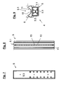
- the light-emitting diodes of a luminaire module 4, 4 ', 4 " are arranged on two separate printed circuit boards 10 and form a first and second light-emitting diode chain comprising, for example, 8 to 16, preferably 12 light-emitting diodes 13.
- the first and second light-emitting diode chains are independently controllable, so that if one of the two light-emitting diode chains fails, a redundant light-emitting diode chain remains ready for use.
- a heat-resistant, but thermally conductive adhesive is used to attach the circuit board 10 on the elongated and / or plate-shaped support body 6.
- the adhesive may be formed for example by an adhesive film made of plastic, which has very good thermal properties.
- the adhesive film may be formed, for example, glass fiber reinforced and have a smooth surface structure.
- the adhesive films used have very good heat resistance properties with high insulation capacity at low mounting pressure. These can be used at temperatures up to 200 ° C and have a thermal conductivity of, for example, 1.4 W / mk
- the power supply unit 8 is used to power the lighting module 4, 4 ', 4 "and generates, for example, from a conventional AC voltage of 230 V, a constant DC voltage of about 24 volts.
- control unit is designed for dimming the light-emitting diodes 10, which possibly cooperates with a central control unit 5.
- the brightness of the LEDs 13 in this case depends directly on the applied current, so that by controlling the light emitting diodes 13 supplied current intensity dimming of the light emitting diodes 13 is possible.
- At least one further plug connection 12, which cooperates with the plug connection 9 of the luminaire module 4, is provided on the holding profile 5, which is provided for supplying the mains voltage and possibly control signals.
- first and second Plug connection 9.1, 9.2 per luminaire module 4, 4 ', 4 "and a further first and second plug connection 12.1, 12.2 per assigned holding profile 5, 5', 5" be provided, each in the region of the free ends of the bottom 6.2 of the elongate support body. 6 or the holding section 5.3 of the holding section 5 are fixed and thus ensure the pluggability of the lamp module 4, 4 ', 4 ".
- the luminaire modules 4, 4 ', 4 are also designed to be exchangeable during operation of the luminaire 1.
- the luminaire module 4, 4', 4" "dimmed” luminous modules of the tunnel luminaire 1 automatically change to the full light output highly controlled to ensure a favorable illumination.
- the luminaire modules 4, 4 ', 4 "provided in the tunnel luminaire 1 can be switched separately, preferably via a digital switching signal. , 4 "off when a voltage at the digital switching input and turned on when there is no voltage at the digital switching input, thereby ensuring that the lamp module 4, 4 ', 4" remains switched on even in breakthrough or damage to the central control unit.
- a method for controlling at least one luminaire 1 by means of a central control unit is likewise the subject matter of the invention, according to which a tunnel luminaire 1 according to the invention is operated with a plurality of luminaire modules 4, 4 ', 4 "in interval operation. 4 ', 4 "controlled separately and operated at different time intervals.
- At least one luminaire module 4, 4 ', 4 " is operated in a first time interval and at least one further luminaire module 4, 4', 4" in a second time interval, the first and second time intervals being different from one another.
- the first luminaire module 4 can be switched on Monday, the second luminaire module 4 'on Tuesday, and the third luminaire module 4 "on the following Wednesday. Then the cycle starts to run again.
- the operating time of the luminaire modules 4, 4 ', 4 can be increased particularly effectively and the energy consumption of the tunnel luminaire 1 can be effectively reduced.
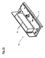
- FIGS. 10 to 13 a second embodiment of the tunnel lamp 1 is shown, in which in the interior of the lamp housing 2, a first and second lamp module 4, 4 'are provided which are connected via a first and second support section 5, 5' with the lamp housing 2.
- the control unit 7 and the power supply of the light modules 4, 4 'provided power supply unit 8 on a between the first and second light module 4, 4' arranged in the light housing 2 supply module 14 is taken, which also on the first and second holding profile. 5 , 5 'is connected to the lamp housing 2.
- the first and second retaining profile 5, 5 ' also form together with the elongated and / or plate-shaped support body 6 of the respective lamp module 4, 4', 4 "a two-part cooling arrangement, wherein the first and second retaining profile 5, 5 'turn the lower
- the first and second retaining profile 5, 5 'are for example, a U-shaped profile element with two opposing legs 5.1, 5.2 and 5.1, respectively
- the two holding profiles 5, 5 'are arranged parallel to one another and in each case the first legs 5.1, 5.1' with the flat underside 6.2 of the elongated and / or plate-shaped support body 6 is connected, which is realized in the present embodiment in the form of a rectangular support plate.
- the opposite second legs 5.2, 5.2 'of the two holding profiles 5, 5' are each thermally conductively connected to the lamp housing 2, in such a way that a large-area heat transfer area is created, the most efficient heat transfer from the support plate 6, on the first leg 5.1 , 5.1 ', the connecting sections 5.3, 5.3' and the second leg 5.2, 5.2 'to the bottom 2.6 of the lamp housing 2 guaranteed.
- a reflector attachment module 15 per light module 4, 4 ' is additionally provided, which mounted on the top 6.1 of the support plate 6 printed circuit board 10th surrounds.
- the reflector attachment module 15 has two cross-sectionally substantially V-shaped, elongate profile sections 15.1, 15.2, which are spaced apart from one another via a plurality of reflector lamellae 15.3.
- the reflector blades 15.3 preferably close in the mounted state an acute angle, i. smaller than 90 °, with the flat top 6.1 of the support plate 6 a, and with respect to the longitudinal axis L of the tunnel lamp 1 enclosing plane which is perpendicular to the flat top 6.1 of the support plate 6.
- the elongate profile sections 15.1, 15.2 form an outwardly widening reflector channel, by means of which the light generated via the LEDs 13 of the printed circuit board 10 is suitably reflected and scattered.
- the distance between the two elongated profile sections 15.1, 15.2 of the reflector attachment module 15 is selected such that by fastening the reflector attachment module 15 on the flat top 6.1 of the support plate 6 edge-side terminals of the circuit board 10 takes place.
- the reflector attachment module 15 is embodied in co-beam technology, ie, the guidance of the rays of the light generated by light emitting diodes 13 takes place by means of the reflector fins 15.3 in the direction of travel of the tunnel.
- the lights 1 are preferably attached to the tunnel side walls at a distance from the road of about 2 to 3m, wherein the longitudinal axis L of the respective tunnel lamp 1 runs in the direction of travel. This allows a particularly uniform and pleasant for the driver illumination of a tunnel can be achieved
Landscapes
- Engineering & Computer Science (AREA)
- General Engineering & Computer Science (AREA)
- Non-Portable Lighting Devices Or Systems Thereof (AREA)
- Arrangement Of Elements, Cooling, Sealing, Or The Like Of Lighting Devices (AREA)
Applications Claiming Priority (1)
| Application Number | Priority Date | Filing Date | Title |
|---|---|---|---|
| DE102009041292 | 2009-09-15 |
Publications (1)
| Publication Number | Publication Date |
|---|---|
| EP2295847A2 true EP2295847A2 (fr) | 2011-03-16 |
Family
ID=43296942
Family Applications (1)
| Application Number | Title | Priority Date | Filing Date |
|---|---|---|---|
| EP10009533A Withdrawn EP2295847A2 (fr) | 2009-09-15 | 2010-09-14 | Luminaire, en particulier luminaire de tunnel |
Country Status (2)
| Country | Link |
|---|---|
| EP (1) | EP2295847A2 (fr) |
| DE (1) | DE102010045297A1 (fr) |
Cited By (2)
| Publication number | Priority date | Publication date | Assignee | Title |
|---|---|---|---|---|
| EP3627045A1 (fr) * | 2018-09-21 | 2020-03-25 | Broll Systemtechnik KG | Module d'insertion de moyen d'éclairage |
| WO2021057941A1 (fr) * | 2019-09-27 | 2021-04-01 | 苏州欧普照明有限公司 | Lampe linéaire |
Families Citing this family (5)
| Publication number | Priority date | Publication date | Assignee | Title |
|---|---|---|---|---|
| DE102012101950A1 (de) * | 2012-03-08 | 2013-09-12 | Rp-Technik E.K. | Rettungszeichenleuchte, insbesondere für die Installation in elektrifizierten Bahntunneln |
| DE102013219333A1 (de) * | 2013-09-25 | 2015-03-26 | Osram Gmbh | LED-Leuchte |
| EP2963340B1 (fr) | 2014-07-05 | 2018-09-05 | Swareflex GmbH | Support pour une disposition de lentilles sur un dispositif d'illumination |
| DE202017102627U1 (de) | 2017-05-03 | 2017-05-22 | Broll Systemtechnik Kg | Tunnelleuchte |
| DE202017103636U1 (de) | 2017-06-20 | 2017-07-12 | Broll Systemtechnik Kg | Tunnelleuchte |
Citations (1)
| Publication number | Priority date | Publication date | Assignee | Title |
|---|---|---|---|---|
| DE102008009945A1 (de) | 2008-02-20 | 2009-08-27 | Christian Bartenbach | Tunnelleuchte |
-
2010
- 2010-09-14 EP EP10009533A patent/EP2295847A2/fr not_active Withdrawn
- 2010-09-14 DE DE102010045297A patent/DE102010045297A1/de not_active Withdrawn
Patent Citations (1)
| Publication number | Priority date | Publication date | Assignee | Title |
|---|---|---|---|---|
| DE102008009945A1 (de) | 2008-02-20 | 2009-08-27 | Christian Bartenbach | Tunnelleuchte |
Cited By (3)
| Publication number | Priority date | Publication date | Assignee | Title |
|---|---|---|---|---|
| EP3627045A1 (fr) * | 2018-09-21 | 2020-03-25 | Broll Systemtechnik KG | Module d'insertion de moyen d'éclairage |
| WO2021057941A1 (fr) * | 2019-09-27 | 2021-04-01 | 苏州欧普照明有限公司 | Lampe linéaire |
| US11821595B2 (en) | 2019-09-27 | 2023-11-21 | Suzhou Opple Lighting Co., Ltd. | Linear lamp |
Also Published As
| Publication number | Publication date |
|---|---|
| DE102010045297A1 (de) | 2011-05-26 |
Similar Documents
| Publication | Publication Date | Title |
|---|---|---|
| EP2295847A2 (fr) | Luminaire, en particulier luminaire de tunnel | |
| EP2151899B1 (fr) | Système de bande lumineuse | |
| DE202006018081U1 (de) | Beleuchtungseinheit für Fahrzeugscheinwerfer und Fahrzeugscheinwerfer | |
| DE102011076128A1 (de) | Trägersystem und Lichtmodul zur Befestigung daran | |
| WO2012032191A1 (fr) | Dispositif d'éclairage à del | |
| DE102008016697A1 (de) | Leuchte | |
| DE102007043861A1 (de) | Leuchtmodul | |
| EP2350522A1 (fr) | Dispositif d éclairage à led, notamment pour tunnels | |
| DE102012106165B4 (de) | Beleuchtungsanordnung | |
| DE202012103474U1 (de) | LED-Leuchte | |
| EP1341142B1 (fr) | Source lumineuse à diodes éléctroluminescentes | |
| DE102014214818A1 (de) | Leuchtmittel-Modul und Leuchte mit mehreren Leuchtmittel-Modulen | |
| EP3418629A1 (fr) | Luminaire pour tunnel | |
| EP2532955A2 (fr) | Lampe à diodes électroluminescentes et circuit de commande d'une source lumineuse | |
| AT525207B1 (de) | Leuchte zur Beleuchtung von Pflanzen | |
| DE202016103954U1 (de) | Leuchte mit zwei Gehäuseteilen | |
| DE102010046478A1 (de) | Leuchtenanordnung mit einem profilierten Basiskörper zur Aufnahme mindestens eines Leuchtmittels | |
| DE102020208809B4 (de) | Leuchtanordnung mit einer schlauchförmigen Leuchtvorrichtung | |
| DE102011001113B4 (de) | Leuchte | |
| DE102016104342B4 (de) | Beleuchtungsmodul und Straßen- oder Wegleuchte | |
| AT516656B1 (de) | Ablängbarer Leuchtmittelträger und Einbauleuchte | |
| EP2910843B1 (fr) | Lampe | |
| WO2011104256A2 (fr) | Dispositif pour faire fonctionner une source de lumière à led | |
| DE202018101279U1 (de) | Beleuchtungsvorrichtung | |
| DE102012103042B4 (de) | Beleuchtungsanordnung |
Legal Events
| Date | Code | Title | Description |
|---|---|---|---|
| PUAI | Public reference made under article 153(3) epc to a published international application that has entered the european phase |
Free format text: ORIGINAL CODE: 0009012 |
|
| AK | Designated contracting states |
Kind code of ref document: A2 Designated state(s): AL AT BE BG CH CY CZ DE DK EE ES FI FR GB GR HR HU IE IS IT LI LT LU LV MC MK MT NL NO PL PT RO SE SI SK SM TR |
|
| AX | Request for extension of the european patent |
Extension state: BA ME RS |
|
| STAA | Information on the status of an ep patent application or granted ep patent |
Free format text: STATUS: THE APPLICATION IS DEEMED TO BE WITHDRAWN |
|
| 18D | Application deemed to be withdrawn |
Effective date: 20140401 |