EP2963340B1 - Support pour une disposition de lentilles sur un dispositif d'illumination - Google Patents
Support pour une disposition de lentilles sur un dispositif d'illumination Download PDFInfo
- Publication number
- EP2963340B1 EP2963340B1 EP14175893.8A EP14175893A EP2963340B1 EP 2963340 B1 EP2963340 B1 EP 2963340B1 EP 14175893 A EP14175893 A EP 14175893A EP 2963340 B1 EP2963340 B1 EP 2963340B1
- Authority
- EP
- European Patent Office
- Prior art keywords
- wall
- support
- lateral wall
- mounting
- carrier
- Prior art date
- Legal status (The legal status is an assumption and is not a legal conclusion. Google has not performed a legal analysis and makes no representation as to the accuracy of the status listed.)
- Not-in-force
Links
- 239000011796 hollow space material Substances 0.000 claims description 9
- XAGFODPZIPBFFR-UHFFFAOYSA-N aluminium Chemical compound [Al] XAGFODPZIPBFFR-UHFFFAOYSA-N 0.000 claims description 8
- 229910052782 aluminium Inorganic materials 0.000 claims description 8
- 239000000463 material Substances 0.000 claims description 8
- 238000004381 surface treatment Methods 0.000 claims description 6
- 238000013461 design Methods 0.000 claims description 3
- 238000005192 partition Methods 0.000 description 24
- 230000008901 benefit Effects 0.000 description 13
- 230000017525 heat dissipation Effects 0.000 description 11
- 238000000034 method Methods 0.000 description 4
- 230000000149 penetrating effect Effects 0.000 description 4
- 230000008569 process Effects 0.000 description 4
- 239000012080 ambient air Substances 0.000 description 3
- 238000005520 cutting process Methods 0.000 description 3
- 230000007613 environmental effect Effects 0.000 description 3
- 230000001681 protective effect Effects 0.000 description 3
- 230000005855 radiation Effects 0.000 description 3
- 238000013022 venting Methods 0.000 description 3
- XEEYBQQBJWHFJM-UHFFFAOYSA-N Iron Chemical compound [Fe] XEEYBQQBJWHFJM-UHFFFAOYSA-N 0.000 description 2
- 229910045601 alloy Inorganic materials 0.000 description 2
- 239000000956 alloy Substances 0.000 description 2
- 230000000712 assembly Effects 0.000 description 2
- 238000000429 assembly Methods 0.000 description 2
- 239000000969 carrier Substances 0.000 description 2
- 230000008859 change Effects 0.000 description 2
- 239000011248 coating agent Substances 0.000 description 2
- 238000000576 coating method Methods 0.000 description 2
- 230000000295 complement effect Effects 0.000 description 2
- 238000001816 cooling Methods 0.000 description 2
- 238000005260 corrosion Methods 0.000 description 2
- 230000007797 corrosion Effects 0.000 description 2
- 239000011159 matrix material Substances 0.000 description 2
- 239000002245 particle Substances 0.000 description 2
- 229910000838 Al alloy Inorganic materials 0.000 description 1
- VYZAMTAEIAYCRO-UHFFFAOYSA-N Chromium Chemical compound [Cr] VYZAMTAEIAYCRO-UHFFFAOYSA-N 0.000 description 1
- RYGMFSIKBFXOCR-UHFFFAOYSA-N Copper Chemical compound [Cu] RYGMFSIKBFXOCR-UHFFFAOYSA-N 0.000 description 1
- 240000006829 Ficus sundaica Species 0.000 description 1
- FYYHWMGAXLPEAU-UHFFFAOYSA-N Magnesium Chemical compound [Mg] FYYHWMGAXLPEAU-UHFFFAOYSA-N 0.000 description 1
- XUIMIQQOPSSXEZ-UHFFFAOYSA-N Silicon Chemical compound [Si] XUIMIQQOPSSXEZ-UHFFFAOYSA-N 0.000 description 1
- 229910000831 Steel Inorganic materials 0.000 description 1
- RTAQQCXQSZGOHL-UHFFFAOYSA-N Titanium Chemical compound [Ti] RTAQQCXQSZGOHL-UHFFFAOYSA-N 0.000 description 1
- HCHKCACWOHOZIP-UHFFFAOYSA-N Zinc Chemical compound [Zn] HCHKCACWOHOZIP-UHFFFAOYSA-N 0.000 description 1
- 238000005299 abrasion Methods 0.000 description 1
- 230000001154 acute effect Effects 0.000 description 1
- 238000007792 addition Methods 0.000 description 1
- 239000000853 adhesive Substances 0.000 description 1
- 238000004026 adhesive bonding Methods 0.000 description 1
- 230000001070 adhesive effect Effects 0.000 description 1
- 239000003570 air Substances 0.000 description 1
- 238000002048 anodisation reaction Methods 0.000 description 1
- 238000007743 anodising Methods 0.000 description 1
- 230000015572 biosynthetic process Effects 0.000 description 1
- 229910052804 chromium Inorganic materials 0.000 description 1
- 239000011651 chromium Substances 0.000 description 1
- 238000009833 condensation Methods 0.000 description 1
- 230000005494 condensation Effects 0.000 description 1
- 239000000470 constituent Substances 0.000 description 1
- 229910052802 copper Inorganic materials 0.000 description 1
- 239000010949 copper Substances 0.000 description 1
- 238000011161 development Methods 0.000 description 1
- 230000018109 developmental process Effects 0.000 description 1
- 239000000428 dust Substances 0.000 description 1
- 238000001125 extrusion Methods 0.000 description 1
- 230000006872 improvement Effects 0.000 description 1
- 229910052742 iron Inorganic materials 0.000 description 1
- 238000002955 isolation Methods 0.000 description 1
- 239000004922 lacquer Substances 0.000 description 1
- 229910052749 magnesium Inorganic materials 0.000 description 1
- 239000011777 magnesium Substances 0.000 description 1
- WPBNNNQJVZRUHP-UHFFFAOYSA-L manganese(2+);methyl n-[[2-(methoxycarbonylcarbamothioylamino)phenyl]carbamothioyl]carbamate;n-[2-(sulfidocarbothioylamino)ethyl]carbamodithioate Chemical compound [Mn+2].[S-]C(=S)NCCNC([S-])=S.COC(=O)NC(=S)NC1=CC=CC=C1NC(=S)NC(=O)OC WPBNNNQJVZRUHP-UHFFFAOYSA-L 0.000 description 1
- 238000004519 manufacturing process Methods 0.000 description 1
- 239000004033 plastic Substances 0.000 description 1
- 238000003825 pressing Methods 0.000 description 1
- 239000011241 protective layer Substances 0.000 description 1
- 150000003839 salts Chemical class 0.000 description 1
- 239000000565 sealant Substances 0.000 description 1
- 229910052710 silicon Inorganic materials 0.000 description 1
- 239000010703 silicon Substances 0.000 description 1
- 239000010959 steel Substances 0.000 description 1
- 238000003860 storage Methods 0.000 description 1
- 229910052719 titanium Inorganic materials 0.000 description 1
- 239000010936 titanium Substances 0.000 description 1
- 238000012546 transfer Methods 0.000 description 1
- 238000011282 treatment Methods 0.000 description 1
- 238000009423 ventilation Methods 0.000 description 1
- XLYOFNOQVPJJNP-UHFFFAOYSA-N water Substances O XLYOFNOQVPJJNP-UHFFFAOYSA-N 0.000 description 1
- 239000013585 weight reducing agent Substances 0.000 description 1
- 239000011701 zinc Substances 0.000 description 1
- 229910052725 zinc Inorganic materials 0.000 description 1
Images


Classifications
-
- F—MECHANICAL ENGINEERING; LIGHTING; HEATING; WEAPONS; BLASTING
- F21—LIGHTING
- F21V—FUNCTIONAL FEATURES OR DETAILS OF LIGHTING DEVICES OR SYSTEMS THEREOF; STRUCTURAL COMBINATIONS OF LIGHTING DEVICES WITH OTHER ARTICLES, NOT OTHERWISE PROVIDED FOR
- F21V15/00—Protecting lighting devices from damage
- F21V15/01—Housings, e.g. material or assembling of housing parts
- F21V15/013—Housings, e.g. material or assembling of housing parts the housing being an extrusion
Definitions
- the invention relates to a support for a lens arrangement of a lighting device according to the preamble of patent claim 1.
- Carrier for a lens arrangement of a lighting device in particular a lighting device for a tunnel lighting, wherein the lens arrangement comprises a plurality of light emitting diodes having lenses are known.
- Lighting means such as light bulbs release heat especially at their light-emitting surfaces. This leads to a heat load of the illuminant receiving carrier.
- light-emitting diodes so-called LEDs
- the light-emitting diodes having lenses are arranged side by side in a plurality, so that a large amount of heat is emitted in particular on a mounting surface of the lens, which applies to dissipate it from the lamp via the carrier.
- the tunnel light comprises a holding profile accommodated in a carrier and formed independently of the carrier, which lighting module is designed such that it can be received.
- the lighting modules consist of a plurality of light emitting diodes. A heat dissipation takes place both via the retaining profile and via the carrier, which receives the retaining profile.
- the publication DE 10 2011 111 953 A1 also discloses a support for a lens assembly of a tunnel lamp, wherein the support is designed to receive a lens assembly.
- the carrier is formed like a hollow profile, wherein the lens assembly is to be fastened directly to the carrier, so that a trained independently of the carrier retaining profile is abriebbar, thereby reducing manufacturing costs.
- the carrier has two side walls, between which there are a carrier wall for fixing the carrier and a mounting wall for fixing the lens arrangement to the carrier. Both the side walls and the support wall and the mounting wall are spaced apart, so that a cavity is formed between them.
- the carrier has in its cross-sectional profile with respect to the cavity convex side walls or side walls with an outer curvature and on the side walls of the carrier formative formed rib structure for heat dissipation.
- DE 20 2011 003 828 U1 discloses a support for a lens assembly of a lighting device comprising a first sidewall and a second sidewall oppositely disposed between the first sidewall and the second sidewall, a support wall connecting the first sidewall and the second sidewall, and the first sidewall opposing the support wall and the second side wall connecting mounting wall, wherein the first side wall, the second side wall, the support wall and the mounting wall are formed spaced from each other and between them along a longitudinal axis of the support extending cavity is formed, based on the cavity, the first side wall and / or the second side wall are curved in their transverse extension.
- US 2013/0170209 A1 discloses a support for a lens assembly comprising a first sidewall and a second sidewall oppositely disposed to the first sidewall, wherein the first sidewall and the second sidewall connecting the first sidewall and the second sidewall and a support wall oppositely disposed the first sidewall and second side wall connecting mounting wall, wherein the first side wall, the second side wall, the support wall and the mounting wall are spaced from each other and formed between them along a longitudinal axis of the carrier extending cavity, wherein with respect to the cavity, the first side wall and / or second side wall are formed concavely curved in their extension.
- US 2012/0229025 A1 discloses a profile which is suitable as a support for a lens arrangement, but is not intended for this purpose.
- Object of the present invention is to provide a support for a lens assembly of a lighting device, which has an improved heat dissipation with a simple structure.
- the support according to the invention for a lens arrangement of a lighting device has a first side wall and a second side wall arranged opposite the first side wall, wherein a support wall and a mounting wall oppositely arranged between the first side wall and the second side wall are formed.
- the first side wall and the second side wall are connected to each other by means of the support wall and the mounting wall.
- the first sidewall, the second sidewall, the support wall and the mounting wall are spaced apart from one another such that a cavity extending along a longitudinal axis of the support is formed between them.
- the first side wall and / or the second side wall are concave relative to the cavity in their transverse extension. In other words, the first side wall and / or the second side wall in their profile on an inner curvature with respect to the cavity.
- This inner curvature of the side walls or the concave curvature of the side walls relative to the cavity has the significant advantage that their free convection surfaces for heat dissipation of heat generated by the lens assembly during operation of the lighting device can be increased in a simple manner without a required space requirement of Change carrier.
- the heat generated by the lens assembly during operation of the lighting device is transmitted via heat conduction from the lenses to the mounting wall and from there further via the side walls and the support wall of the support.
- a heat transfer into the cavity of the wearer This accumulating by the heat conduction amount of heat is as fast as possible to dissipate an environment of the lighting device, as it may otherwise be next to damage
- the wearer may, for example, suffer damage to lenses and light-emitting diodes incorporated in the lenses or cables arranged in the possibly cavity.
- a fast heat dissipation with the help of a large surface can be realized by free convection and heat radiation. Due to a curvature of the side walls, a first side surface of the first side wall facing away from the cavity and / or a second side surface of the second side wall facing away from the cavity can be enlarged in a simple manner.
- the side wall which is concave relative to the hollow space, it is possible to comply with the intended space requirement of the lighting device or luminaire and nevertheless to achieve an enlargement of the first side surface or second side surface provided for convection. This means that only the side walls are to be changed in their curvature in order to obtain a heat dissipation adapted to a performance of the lens arrangement.
- the tunnels generally have a typical tunnel curvature. That is, the tunnels are generally not square or square in cross-section, but are parabolic. Starting from a roadway in the direction of a tunnel ceiling, a possible space formed transversely to a tunnel longitudinal axis becomes ever smaller. That is, for example, a sidewall formed concave relative to the cavity would experience confinement by a tunnel wall. However, the concave first side wall and second side wall may extend toward the cavity to provide sufficient surface area for heat removal.
- the carrier wall has a first width, which is greater than a second width of the mounting wall.
- first portions of the side walls extend in their transverse extent over their formed in the region of the mounting wall second portions.
- An additional advantage of this design is a further improved heat dissipation.
- the dissipated heat increases along the concave side walls in the direction of the support wall, wherein it undergoes a change of direction of its flow direction for improved removal due to the concavity.
- the heat is conducted away from the support wall and generally away from the support due to the larger first width of the support wall in its flow direction.
- the larger first width of the support wall achieves an acute angle formed between the support wall and the side wall in the direction of the cavity so that the flow direction of the dissipated heat in the area of the cutting edge has an obtuse angle relative to the support wall.
- the heat at the cutting edge can be removed tangentially to the support wall.
- a further advantage results from the fact that the support wall surface of the support wall, which is largely remote from the cavity, is between the tunnel ceiling and the support wall surface a flow channel is formed, which according to the ambient conditions has a flow of ambient air, so that quasi a forced convection is formed here. This promotes rapid heat dissipation of the heat emitted to the support wall of the lens assembly.
- the first side wall and / or the second side wall in its formed between the support wall and the mounting wall extension extending from the support wall across the mounting wall extending away.
- a further advantage of this over the mounting wall facing away from the support wall extension beyond the mounting wall is a positioning and holding aid for the lens assembly, which is thus formed between the extension of the first side wall and the second side wall.
- the first side wall and the second side wall in its extension, starting from the support wall in the direction of the mounting wall is formed so large that are formed on a remote from the support wall first mounting panel extending in the direction of the longitudinal axis extending guide rails, form an extension of the side surfaces beyond the mounting wall.
- a further additional improvement of the heat dissipation is to be achieved with ribs which are formed on an outer surface of the first side wall and the second side wall, respectively.
- the first side wall and / or the second side wall have ribs on their first side wall surface or second side wall surface, which faces away from the cavity.
- turbulences are created on the first side wall surface and the second side wall surface, which promote convection.
- the ribs extend along the longitudinal axis and are thus easy to produce in an example. Extrusion process.
- the cavity is separated by means of a partition in at least two cavities, so that it is advantageous for receiving on the one hand electrical components, such as power supplies, cables for power supply, as well as other electrical line serving components and on the other hand for receiving mechanical components of, for example, carrier and or lens assembly fasteners.
- electrical components such as power supplies, cables for power supply, as well as other electrical line serving components
- mechanical components of, for example, carrier and or lens assembly fasteners.
- the cavity has a first dividing wall extending along the longitudinal axis and a second dividing wall extending along the longitudinal axis and opposite the first dividing wall and spaced from the first dividing wall, wherein the first trend wall and the second dividing wall are each provided with a bearing profile.
- the bearing profile serve the first partition and the second partition of a storage of the wearer. If the carrier is to be mounted on a standardized lamppost, such as a mast of a street lamp or a mast on a tarmac of an airport, the bearing profile of the two partitions is formed complementary to a circumference of a round cross section of the mast. This means that the carrier has at the same time a receiving means for receiving the carrier on a pole due to its special configuration of the partitions.
- the partitions serve as structural elements for realizing an improved rigidity and stability of the carrier, so that the side walls, the mounting wall and the support wall can be formed with a relatively small wall thickness. This in turn serves a cost and weight reduction.
- the carrier offers the possibility of easy mounting on a rope.
- the grooves can also be used for a device carrier which is accommodated in the cavity or in one of the cavity cells. That is, the equipment carrier is immovably fixed to the grooves on the carrier by means of a corresponding to the groove positively formed and received in the groove receiving element.
- the mounting wall has receiving openings, wherein the receiving openings, the mounting wall are formed in its wall thickness completely penetrating.
- the lens arrangement On a lateral surface facing away from the cavity, the lens arrangement is to be fastened to the carrier.
- Electrical lines which serve to supply power to the lens arrangement, can be reliably protected against environmental influences, such as, for example, moisture in the cavity. With the help of the receiving openings, the lines can be performed in a simple manner, starting from the lens assembly in the cavity, or out of the cavity to the lens assembly.
- protective sleeves which are advantageously made of a plastic, ideally rubber. Rubber has the advantage that it is not conductive with high elasticity, so that it can be positively and sealingly introduced into the receiving openings. Furthermore, these receiving openings serve to secure the lens arrangement.
- the cavity can be closed at one end of the support and at the other end of the support by means of a first cover or a second cover.
- the covers are detachably arranged on the side walls, the support wall and / or the mounting wall.
- the carrier is made of an aluminum material.
- Aluminum materials are generally characterized by their low density, so that even large components have a low weight compared to, for example, steel. Furthermore, because of their high thermal conductivity, aluminum materials have a very good price-performance ratio, so that a cost-effective carrier with simultaneously high heat dissipation can be produced.
- a mounting wall surface of the mounting wall plan it is advantageous to form a mounting wall surface of the mounting wall plan, so that a flat and easy mounting of the lens assembly is possible.
- a screw connection can be used for a secure connection of the lens arrangement to the mounting wall or to the mounting wall surface.
- a material-locking connection in the form of gluing, in which case attention must be paid to airtightness between the mounting wall surface and the lens arrangement.
- the carrier has, in particular on its first side wall surface, its second side wall surface, its support wall surface and its mounting wall surface, a surface treatment for protection against environmental influences and for corrosion resistance.
- a surface treatment for protection against environmental influences and for corrosion resistance This means that the carrier or the lighting device can be used in coastal areas and near the lake, for example. Harbors, where a pronounced corrosive high salt content of the ambient air prevails.
- This surface treatment may be in the form of a coating, which additionally has the advantage of increasing the heat-emitting surface.
- the surface treatment can be realized with an anodizing process for producing an oxidic protective layer of the aluminum material.
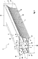
- An inventive carrier 1 is according to a in Fig. 1 constructed structure.
- the support 1 for a lens arrangement 2 of a lighting device comprises a first side wall 3 and a second side wall 4 arranged opposite the first side wall 3. Between the first side wall 3 and the second side wall 4 is a support wall 5 connecting the first side wall 3 and the second side wall 4 positioned.
- the support wall 5 is arranged opposite to a connecting the first side wall 3 and the second side wall 4 mounting wall 6 is formed.
- the first side wall 3, the second side wall 4, the support wall 5 and the mounting wall 6 are arranged at a distance from each other so that a cavity 8 extending along a longitudinal axis 7 of the support 1 is formed between them.
- the walls 3, 4, 5, 6 are made in one piece with each other in a pultrusion process. This favors a tightness of the cavity 8 against penetrating moisture and / or moisture, since the walls 3, 4, 5, 6 without the aid of a sealant are positively and materially connected to each other.
- a further advantage is that the carrier 1 can be produced as an endless profile and sections to be cut to an appropriate length.
- Fig. 2 shows the carrier 1 in a cross section.
- the cavity 8 has a first partition 9 and a second partition 10, which extend transversely, in this embodiment, perpendicular to the longitudinal axis 7 and in the direction of the longitudinal axis 7.
- the first partition wall 9 and the second partition wall 10 are spaced from each other axially and in parallel. With the help of the two partitions 9, 10, the cavity 8 divides into three cavity cells, a first cavity cell 11, a second cavity cell 12 and a third cavity cell 13.
- the carrier 1 is equipped for mounting on a rope or a pole with corresponding receiving elements.
- the first partition 9 and the second partition 10 each have a bearing profile 14.
- This bearing profile 14 is suitable for receiving a mast with a round cross section.
- the bearing profile 14 is formed in the form of a partial circle, wherein the first partition wall 9 and the second partition wall 10 of this part-circular bearing profile 14 each have along the longitudinal axis 7 mirrored to each other.
- the bearing profile 14 may be formed adapted to a standard for mast sections.
- the support wall 5 has along the longitudinal axis 7 extending, the cavity 8 facing grooves 15 formed.
- the grooves 15 have a specific groove profile 16, in which firmly connected to a rope, the groove profile 16 form-fitting adapted not shown rope elements are inserted.
- the carrier 1 is flexibly mountable on carrier devices such as mast or rope without the additional changes to the carrier 1 are made. Furthermore, retaining elements 30 can be attached to the support 1 for easy ceiling mounting, the support wall 5 serving to receive the retaining elements 30.
- the holding members 30 are formed in the form of U-shaped support angle. These are connected to the support wall 5 facing the formed angular surface by means of a releasable connection, which is a screw in the second embodiment, connected to the carrier 1.
- a releasable connection which is a screw in the second embodiment, connected to the carrier 1.
- the holding member 30 is formed in two parts, so that a first holding element part 31 on a ceiling, not shown, for example. A tunnel ceiling, and the second holding element part 32 is mounted on the carrier 1.
- the first holding element part 31 and the second holding element part 32 are connected to one another by means of a screw connection.
- mutually facing ends of the first holding element part 31 and the second holding element part 32 are complementary in the form of a snap or clip connection.
- the carrier 1 with the second holding element part 32 is to be correspondingly positioned on the first holding element part 31 and can be brought into its final assembly position by, for example, a short pressing with audible latching and latching of the holding element parts 31, 32, so that the carrier 1 easily mounted quickly in its intended location.
- the cavity 8 facing tubular formed longitudinal grooves 17 between wall longitudinal edges 33 of the support wall 5 and the first side wall 3, the support wall 5 and the second side wall 4, the mounting wall 6 and the first side wall 3 and the mounting wall 6 and the second side wall 4 configured ,
- These longitudinal grooves 17 are thus assigned in this embodiment, the first cavity cell 11 and the third cavity cell 13.
- the longitudinal grooves 17 are likewise positioned on a first partition wall surface 18 of the first partition wall 9 facing the first cavity cell 11 and on a second partition wall surface 19 of the second partition wall 10 facing the third cavity cell 13 on the bearing profiles 14 of the partition walls 9, 10.
- the longitudinal grooves 17 can serve to receive electrical cables and lines, so that a power supply unit for a power supply to a lens assembly 2 mounted on the mounting wall surface 20 facing away from the cavity 8 can be connected to one of the cavity cells 11, 13.
- the mounting wall 6 receiving openings not shown in detail, which completely penetrate the mounting wall 6 in their wall thickness.
- the receiving openings are made in the form of holes.
- protective sleeves are arranged in the receiving openings. These protective sleeves also serve at the same time to seal against moisture, for example condensation water, which could penetrate between the mounting wall surface 20 and a bottom surface of the lens arrangement 2, not shown, which is connected to the mounting wall surface 20.
- the facing away from the ceiling at a ceiling mounting on the support, thus lying below mounting wall has a planar mounting wall surface 20, which is remote from the support wall 5.
- the support brackets 30 are mounted on the support wall 5 on its side facing away from the cavity 8 formed support wall surface 29.
- Fig. 3 On the first mounting panel are gem.
- Fig. 3 several lens assemblies 2 mounted.
- the lens arrangements 2 have light-emitting diode receiving lenses 21 which are not illustrated in more detail and which are arranged in the form of a matrix.
- the lenses 21 with the LEDs could also be positioned side by side or one behind the other in the form of a row. This depends on a surface to be illuminated or a room to be illuminated.
- the carrier 1 is shown with attached to the mounting wall 6 seven lens assemblies 2 in a bottom view.
- Each lens arrangement 2 has fifteen light-emitting diodes, each accommodated in a lens 21, which are arranged according to a 3 ⁇ 5 matrix.
- the cavity 8 and thus the electrical supply of the lens assembly 2 are protected from penetrating moisture and moisture and dirt, the cavity 8 at one end of the carrier 1 and the other end of the carrier 1 by means of a first lid 23 and a second lid 24 can be closed.
- the lid 23, 24 are fixed by means of a clamping device, not shown, which is in the form of conically formed bolts not shown in detail, on the carrier 1.
- the bolts are received in the longitudinal grooves 17, which are formed on the wall longitudinal edges 33.
- the lid 23, 24 could also be mounted on the carrier 1 with the aid of a detachable screw connection.
- the side wall surfaces 25, 26 are each formed on the side walls 3, 4 facing away from the cavity 8.
- the first side wall 3 and the second side wall 4 are formed in their transverse extension relative to the cavity 8 concave.
- the side walls 3, 4 extend in their extension along the longitudinal axis 7 in the direction of the x-coordinate.
- the transverse extent corresponds to its extension in the direction of the y-coordinate, while an extension in the direction of the z-coordinate corresponds to a wall thickness of the side walls 3, 4.
- the first side wall 3 and the second side wall 4 are in their expansion formed between the support wall 5 and the mounting wall 6, i. in its transverse extent, extending from the support wall 5 extending over the mounting wall 6 of time away.
- This has the advantage that guide rails 27 are configured on the mounting wall surface 20 in the direction of the longitudinal axis 7 for positioning the lens arrangement 2.
- the guide rails 27 have a reinforced wall thickness, since in the region of the guide rails 27, a large heat input of the lens assembly 2 prevails during operation of the lamp.
- first section can be used in particular for heat dissipation in the form of heat radiation.
- the heat radiated from the first section can be at least partially released to the environment without hitting the carrier 1 or the side wall 3, 4.
- the support wall 5 has a first width B1, which is greater than a second width B2 of the mounting wall 6.
- the side walls 3, 4 could extend beyond the support wall 5 in their transverse extent. In this case, a corresponding total height H of the carrier 1 is to be observed.
- the sections of the side walls 3, 4 which extend beyond the support wall 5 are ideally to be arc-shaped, so that an overall height extension possibly increased on account of the sections is avoided. Depending on the radius R formed in the concavity, this can be continued, for example, or the sections have a generally smaller radius of curvature, so that the total height H is maintained.
- the carrier 1 is made of an aluminum material, EN AW-6060, ideally as a hollow profile.
- EN AW-6060 is a standard AlMgSi group aluminum alloy with 0.35-0.6% magnesium as the main constituent and additions of silicon, iron, zinc, titanium, manganese, copper and chromium.
- AlMgSi alloys are the most commonly used hardenable aluminum wrought alloys. By means of various hardening treatments, medium to high strengths can be achieved according to use. In particular, this aluminum material is characterized by good cold workability and high corrosion resistance.
- the carrier 1 has a surface treatment, wherein the surface treatment in the illustrated embodiment is an anodization.
- the carrier 1 could be surface-treated with an anticorrosive coating material, for example in the form of a lacquer.
- the mounting panel 20 is planar, i. just designed.
- the on a non-illustrated circuit board matrix-like positioned lenses 21 with light emitting diodes of the lens assembly 2 are easily and securely fixed to the mounting wall 6.
- Between the circuit board and the mounting panel 20 is airtightness.
- the lens assembly 2 is attached to the mounting panel 20 with an adhesive.
- the ribs 28, due to turbulence generated by the ribs 28 on the side wall surfaces 25, 26, serve to provide improved free convection to release the thermal load created by the electrical supply of the light emitting diodes and associated light and associated heat to the environment to be able to.
- the covers 23, 24 have, in addition to venting and drainage openings 34, a connection 35 for the electrical connection of the power supply, such as an improved representation of the detailed view in FIG Fig. 6 can be removed.
- the carrier has lids 23, 24, which in addition to the venting and drainage openings 34 further ventilation openings 34 'in the region of the first cavity cell 11 and in the region of the third cavity cell 13 have.
- the vent openings 34 ' are formed lssensnutartig, wherein a plurality of longitudinal grooves are arranged parallel to each other.
- the second cover 24 is shown with a connection opening 36 for receiving the connection 35.
- the first lid 23 with the vent openings 34 ' is also to produce. This is particularly advantageous in the case of very long carriers 1 and serves in a simple way to dissipate heat in the first cavity cell 11 and the third cavity cell 13, so that cooling of the second cavity cell 12 is likewise formed by free convection on the dividing walls 9, 10.
- the lid In addition to a recorded in a pin opening 36 by means of a press fit pins 38 for fixing the cover 24 to the mounting wall 6, the lid has various mounting holes 39, by means of which the cover 24 on the side walls 3, 4, on the support wall 5 and on the Mounting wall 6 can be fixed.
- the pin 38 extends in its longitudinal direction, starting from a cover inner surface 41 in the direction of the cavity 8.
- a lid outer surface 40, which faces away from the lid inner surface 41, is flat or planar.
- a forced by means of the vent openings 34 'flow in the cavity 8, starting from the mounting wall 6 in the direction of the support wall 5 may be formed, for example.
- relatively short carriers 1 ambient air for cooling the cavity 8 in the area the mounting wall 6 formed vent openings 34 'flows into the cavity 8 and heated by the formed in the region of the support wall 5 vent openings 34' flows out of the cavity 8.
Landscapes
- Engineering & Computer Science (AREA)
- General Engineering & Computer Science (AREA)
- Arrangement Of Elements, Cooling, Sealing, Or The Like Of Lighting Devices (AREA)
Claims (14)
- Support (1) pour un assemblage de lentilles d'un dispositif d'éclairage, comprenant une première paroi latérale (3) et une seconde paroi latérale (4) procurée en face de ladite première paroi latérale (3), dans lequel une paroi de support (5) reliant ladite première paroi latérale (3) et ladite seconde paroi latérale (4) et une paroi de montage (6) en face de ladite paroi de support (5) et reliant ladite première paroi latérale (3) et ladite seconde paroi latérale (4) sont procurées entre ladite première paroi latérale (3) et ladite seconde paroi latérale (4), dans lequel ladite première paroi latérale (3), ladite seconde paroi latérale (4), ladite paroi de support (5) et ladite paroi de montage (6) sont formées distantes l'une de l'autre, et une cavité (8) s'étendant le long d'un axe longitudinal (7) du support (1) est formée entre elles, dans lequel ladite première paroi latérale (3) et/ou ladite seconde paroi latérale (4) sont formées pour présenter une courbure concave dans leur dimension transversale par rapport à la cavité (8), caractérisé en ce que ladite cavité (8) présente une première cloison de séparation (9) s'étendant le long dudit axe longitudinal (7) et une seconde cloison de séparation (10) s'étendant le long dudit axe longitudinal (7) en face de ladite première cloison de séparation (9) et distante de ladite première cloison de séparation (9), dans lequel ladite première cloison de séparation (9) et ladite seconde cloison de séparation (10) présentent un profil de palier (14).
- Support (1) selon la revendication 1, caractérisé en ce que ladite paroi de support (5) présente une première largeur (B1) qui est plus large qu'une seconde largeur (B2) de ladite paroi de montage (6).
- Support (1) selon la revendication 1 ou 2, caractérisé en ce que ladite première paroi latérale (3) et/ou ladite seconde paroi latérale (4) sont formées pour s'étendre à partir de la paroi de support (5) à travers la paroi de montage (6) dans sa dimension formée entre la paroi de support (5) et la paroi de montage (6).
- Support (1) selon l'une quelconque des revendications précédentes, caractérisé en ce que ladite première paroi latérale (3) et/ou ladite seconde paroi latérale (4) présente des nervures (28) formées sur la surface de sa première paroi latérale (25) et/ou sur la surface de sa seconde paroi latérale (26) formées du côté détourné de la cavité (8).
- Support (1) selon la revendication 4, caractérisé en ce que lesdites nervures (28) s'étendent dans la direction dudit axe longitudinal (7).
- Support (1) selon l'une quelconque des revendications précédentes, caractérisé en ce que ladite cavité (8) est séparée en au moins deux cavités (11, 12, 13) au moyen d'une cloison de séparation (9; 10).
- Support (1) selon la revendication 1, caractérisé en ce que ledit profil de palier (14) est formé pour recevoir un mât ayant une section transversale ronde.
- Support (1) selon l'une quelconque des revendications précédentes, caractérisé en ce que des rainures (15) s'étendant le long de l'axe longitudinal (7) et formées en face de la cavité (8) sont formées sur la paroi de support (5).
- Support (1) selon l'une quelconque des revendications précédentes, caractérisé en ce que ladite paroi de montage (6) présente des ouvertures réceptrices, dans lequel lesdites ouvertures réceptrices sont formées pour traverser l'épaisseur de paroi totale de la paroi de montage (6).
- Support (1) selon la revendication 9, caractérisé en ce que lesdites ouvertures réceptrices présentent des enveloppes protectrices.
- Support (1) selon l'une quelconque des revendications précédentes, caractérisé en ce que ladite cavité (8) peut être fermée à l'une des extrémités du support (1) et sur l'autre extrémité du support (1) au moyen d'un premier couvercle amovible (23) ou d'un second couvercle amovible (24) respectivement.
- Support (1) selon l'une quelconque des revendications précédentes, caractérisé en ce que ledit support (1) est en un matériau aluminium.
- Support (1) selon l'une quelconque des revendications précédentes, caractérisé en ce que ladite paroi de montage (6) est réalisée de manière plane au moins sur sa surface de paroi de montage (20) formée du côté détourné de la cavité (8).
- Support (1) selon l'une quelconque des revendications précédentes, caractérisé en ce que ledit support (1) a subi un traitement de surface.
Priority Applications (1)
| Application Number | Priority Date | Filing Date | Title |
|---|---|---|---|
| EP14175893.8A EP2963340B1 (fr) | 2014-07-05 | 2014-07-05 | Support pour une disposition de lentilles sur un dispositif d'illumination |
Applications Claiming Priority (1)
| Application Number | Priority Date | Filing Date | Title |
|---|---|---|---|
| EP14175893.8A EP2963340B1 (fr) | 2014-07-05 | 2014-07-05 | Support pour une disposition de lentilles sur un dispositif d'illumination |
Publications (2)
| Publication Number | Publication Date |
|---|---|
| EP2963340A1 EP2963340A1 (fr) | 2016-01-06 |
| EP2963340B1 true EP2963340B1 (fr) | 2018-09-05 |
Family
ID=51210250
Family Applications (1)
| Application Number | Title | Priority Date | Filing Date |
|---|---|---|---|
| EP14175893.8A Not-in-force EP2963340B1 (fr) | 2014-07-05 | 2014-07-05 | Support pour une disposition de lentilles sur un dispositif d'illumination |
Country Status (1)
| Country | Link |
|---|---|
| EP (1) | EP2963340B1 (fr) |
Citations (3)
| Publication number | Priority date | Publication date | Assignee | Title |
|---|---|---|---|---|
| US20120229025A1 (en) * | 2011-03-07 | 2012-09-13 | Greendot Technologies, Llc. | Vapor-tight lighting fixture |
| US20130170209A1 (en) * | 2011-12-29 | 2013-07-04 | Posco Led Company Ltd. | Optical semiconductor lighting apparatus |
| US20130271977A1 (en) * | 2012-04-16 | 2013-10-17 | 3Form, Inc. | Adjustable, modular lighting fixture |
Family Cites Families (5)
| Publication number | Priority date | Publication date | Assignee | Title |
|---|---|---|---|---|
| CN201386959Y (zh) * | 2009-03-18 | 2010-01-20 | 深圳市国冶星光电子有限公司 | 大功率led洗墙灯 |
| EP2295847A2 (fr) | 2009-09-15 | 2011-03-16 | Broll Systemtechnik KG | Luminaire, en particulier luminaire de tunnel |
| DE202011003828U1 (de) * | 2010-03-18 | 2011-05-12 | D. Swarovski Kg | Leuchte für eine Deckenbeleuchtung eines Tunnels |
| DE102011111953A1 (de) | 2011-08-30 | 2013-02-28 | Bartenbach Holding Gmbh | Tunnelleuchte |
| TWI437727B (zh) * | 2012-05-31 | 2014-05-11 | 玉晶光電股份有限公司 | LED lighting |
-
2014
- 2014-07-05 EP EP14175893.8A patent/EP2963340B1/fr not_active Not-in-force
Patent Citations (3)
| Publication number | Priority date | Publication date | Assignee | Title |
|---|---|---|---|---|
| US20120229025A1 (en) * | 2011-03-07 | 2012-09-13 | Greendot Technologies, Llc. | Vapor-tight lighting fixture |
| US20130170209A1 (en) * | 2011-12-29 | 2013-07-04 | Posco Led Company Ltd. | Optical semiconductor lighting apparatus |
| US20130271977A1 (en) * | 2012-04-16 | 2013-10-17 | 3Form, Inc. | Adjustable, modular lighting fixture |
Also Published As
| Publication number | Publication date |
|---|---|
| EP2963340A1 (fr) | 2016-01-06 |
Similar Documents
| Publication | Publication Date | Title |
|---|---|---|
| DE102008052869B4 (de) | Leuchte mit LED-Tragschiene | |
| DE102019112105B4 (de) | Elektrofahrzeug mit einer Batterie in Unterfluranordnung | |
| DE102017103654A1 (de) | Batteriegehäuse für eine Fahrzeugbatterie, Fahrzeugbatterie und Elektrofahrzeug | |
| EP3575176B1 (fr) | Véhicule ferroviaire pourvu de logement de câble | |
| EP2647907B1 (fr) | Élément d'éclairage avec réflecteur | |
| EP3468320B1 (fr) | Module électrique dans le boîtier de différents matériaux | |
| DE102011051034A1 (de) | LED Beleuchtungsanordnung | |
| DE202011108518U1 (de) | Montageset für trapezförmige Rippen eines Trapezblechs | |
| DE102020208669B3 (de) | Batterie für ein Kraftfahrzeug und Kraftfahrzeug mit der Batterie | |
| EP3414487B1 (fr) | Système de bande lumineuse à rail de support de forme allongée | |
| EP3056805B1 (fr) | Optique allongée pour module à del | |
| EP2409293A1 (fr) | Dispositif d'éclairage et utilisation | |
| EP2963340B1 (fr) | Support pour une disposition de lentilles sur un dispositif d'illumination | |
| DE202012005765U1 (de) | LED-Einbauleuchte | |
| DE102011119847A1 (de) | Montageset für trapezförmige Rippen eines Trapezblechs | |
| EP1095836B1 (fr) | Boítier sous plancher pour véhicules ferroviaires | |
| DE202017102627U1 (de) | Tunnelleuchte | |
| EP2963343B1 (fr) | Disposition de lentilles pour un dispositif d'illumination et dispositif d'illumination | |
| DE102014217314B4 (de) | Ladeluftkühler für eine Verbrennungskraftmaschine sowie Anordnung eines Ladeluftkühlers an einem Zylinderkopf einer Verbrennungskraftmaschine | |
| DE202011050646U1 (de) | Leuchtröhre | |
| EP1389711B1 (fr) | Lampe à encastrer | |
| DE202012009365U1 (de) | LED-Leuchte | |
| EP3572714B1 (fr) | Composant aérodynamique pour un éclairage par projection plan | |
| DE102009007612B4 (de) | Kühlkörper zur Abfuhr von Wärme von elektronischen Bauteilen und Verfahren zu seiner Herstellung | |
| EP2581657B1 (fr) | Agencement de corps de refroidissement pour une lampe à DEL ainsi que la lampe à DEL |
Legal Events
| Date | Code | Title | Description |
|---|---|---|---|
| PUAI | Public reference made under article 153(3) epc to a published international application that has entered the european phase |
Free format text: ORIGINAL CODE: 0009012 |
|
| AK | Designated contracting states |
Kind code of ref document: A1 Designated state(s): AL AT BE BG CH CY CZ DE DK EE ES FI FR GB GR HR HU IE IS IT LI LT LU LV MC MK MT NL NO PL PT RO RS SE SI SK SM TR |
|
| AX | Request for extension of the european patent |
Extension state: BA ME |
|
| 17P | Request for examination filed |
Effective date: 20160701 |
|
| RBV | Designated contracting states (corrected) |
Designated state(s): AL AT BE BG CH CY CZ DE DK EE ES FI FR GB GR HR HU IE IS IT LI LT LU LV MC MK MT NL NO PL PT RO RS SE SI SK SM TR |
|
| STAA | Information on the status of an ep patent application or granted ep patent |
Free format text: STATUS: EXAMINATION IS IN PROGRESS |
|
| 17Q | First examination report despatched |
Effective date: 20161214 |
|
| RIC1 | Information provided on ipc code assigned before grant |
Ipc: F21V 29/00 20150101ALN20180103BHEP Ipc: F21V 15/01 20060101AFI20180103BHEP |
|
| GRAP | Despatch of communication of intention to grant a patent |
Free format text: ORIGINAL CODE: EPIDOSNIGR1 |
|
| STAA | Information on the status of an ep patent application or granted ep patent |
Free format text: STATUS: GRANT OF PATENT IS INTENDED |
|
| INTG | Intention to grant announced |
Effective date: 20180223 |
|
| GRAS | Grant fee paid |
Free format text: ORIGINAL CODE: EPIDOSNIGR3 |
|
| GRAA | (expected) grant |
Free format text: ORIGINAL CODE: 0009210 |
|
| STAA | Information on the status of an ep patent application or granted ep patent |
Free format text: STATUS: THE PATENT HAS BEEN GRANTED |
|
| AK | Designated contracting states |
Kind code of ref document: B1 Designated state(s): AL AT BE BG CH CY CZ DE DK EE ES FI FR GB GR HR HU IE IS IT LI LT LU LV MC MK MT NL NO PL PT RO RS SE SI SK SM TR |
|
| REG | Reference to a national code |
Ref country code: GB Ref legal event code: FG4D Free format text: NOT ENGLISH |
|
| REG | Reference to a national code |
Ref country code: CH Ref legal event code: EP |
|
| REG | Reference to a national code |
Ref country code: AT Ref legal event code: REF Ref document number: 1038240 Country of ref document: AT Kind code of ref document: T Effective date: 20180915 |
|
| REG | Reference to a national code |
Ref country code: DE Ref legal event code: R096 Ref document number: 502014009358 Country of ref document: DE |
|
| REG | Reference to a national code |
Ref country code: IE Ref legal event code: FG4D Free format text: LANGUAGE OF EP DOCUMENT: GERMAN |
|
| REG | Reference to a national code |
Ref country code: CH Ref legal event code: NV Representative=s name: PATENTANWAELTE SCHAAD, BALASS, MENZL AND PARTN, CH |
|
| REG | Reference to a national code |
Ref country code: NL Ref legal event code: MP Effective date: 20180905 |
|
| REG | Reference to a national code |
Ref country code: LT Ref legal event code: MG4D |
|
| PG25 | Lapsed in a contracting state [announced via postgrant information from national office to epo] |
Ref country code: NO Free format text: LAPSE BECAUSE OF FAILURE TO SUBMIT A TRANSLATION OF THE DESCRIPTION OR TO PAY THE FEE WITHIN THE PRESCRIBED TIME-LIMIT Effective date: 20181205 Ref country code: GR Free format text: LAPSE BECAUSE OF FAILURE TO SUBMIT A TRANSLATION OF THE DESCRIPTION OR TO PAY THE FEE WITHIN THE PRESCRIBED TIME-LIMIT Effective date: 20181206 Ref country code: SE Free format text: LAPSE BECAUSE OF FAILURE TO SUBMIT A TRANSLATION OF THE DESCRIPTION OR TO PAY THE FEE WITHIN THE PRESCRIBED TIME-LIMIT Effective date: 20180905 Ref country code: FI Free format text: LAPSE BECAUSE OF FAILURE TO SUBMIT A TRANSLATION OF THE DESCRIPTION OR TO PAY THE FEE WITHIN THE PRESCRIBED TIME-LIMIT Effective date: 20180905 Ref country code: LT Free format text: LAPSE BECAUSE OF FAILURE TO SUBMIT A TRANSLATION OF THE DESCRIPTION OR TO PAY THE FEE WITHIN THE PRESCRIBED TIME-LIMIT Effective date: 20180905 Ref country code: RS Free format text: LAPSE BECAUSE OF FAILURE TO SUBMIT A TRANSLATION OF THE DESCRIPTION OR TO PAY THE FEE WITHIN THE PRESCRIBED TIME-LIMIT Effective date: 20180905 Ref country code: BG Free format text: LAPSE BECAUSE OF FAILURE TO SUBMIT A TRANSLATION OF THE DESCRIPTION OR TO PAY THE FEE WITHIN THE PRESCRIBED TIME-LIMIT Effective date: 20181205 |
|
| PG25 | Lapsed in a contracting state [announced via postgrant information from national office to epo] |
Ref country code: LV Free format text: LAPSE BECAUSE OF FAILURE TO SUBMIT A TRANSLATION OF THE DESCRIPTION OR TO PAY THE FEE WITHIN THE PRESCRIBED TIME-LIMIT Effective date: 20180905 Ref country code: AL Free format text: LAPSE BECAUSE OF FAILURE TO SUBMIT A TRANSLATION OF THE DESCRIPTION OR TO PAY THE FEE WITHIN THE PRESCRIBED TIME-LIMIT Effective date: 20180905 Ref country code: HR Free format text: LAPSE BECAUSE OF FAILURE TO SUBMIT A TRANSLATION OF THE DESCRIPTION OR TO PAY THE FEE WITHIN THE PRESCRIBED TIME-LIMIT Effective date: 20180905 |
|
| PG25 | Lapsed in a contracting state [announced via postgrant information from national office to epo] |
Ref country code: EE Free format text: LAPSE BECAUSE OF FAILURE TO SUBMIT A TRANSLATION OF THE DESCRIPTION OR TO PAY THE FEE WITHIN THE PRESCRIBED TIME-LIMIT Effective date: 20180905 Ref country code: PL Free format text: LAPSE BECAUSE OF FAILURE TO SUBMIT A TRANSLATION OF THE DESCRIPTION OR TO PAY THE FEE WITHIN THE PRESCRIBED TIME-LIMIT Effective date: 20180905 Ref country code: RO Free format text: LAPSE BECAUSE OF FAILURE TO SUBMIT A TRANSLATION OF THE DESCRIPTION OR TO PAY THE FEE WITHIN THE PRESCRIBED TIME-LIMIT Effective date: 20180905 Ref country code: IT Free format text: LAPSE BECAUSE OF FAILURE TO SUBMIT A TRANSLATION OF THE DESCRIPTION OR TO PAY THE FEE WITHIN THE PRESCRIBED TIME-LIMIT Effective date: 20180905 Ref country code: CZ Free format text: LAPSE BECAUSE OF FAILURE TO SUBMIT A TRANSLATION OF THE DESCRIPTION OR TO PAY THE FEE WITHIN THE PRESCRIBED TIME-LIMIT Effective date: 20180905 Ref country code: NL Free format text: LAPSE BECAUSE OF FAILURE TO SUBMIT A TRANSLATION OF THE DESCRIPTION OR TO PAY THE FEE WITHIN THE PRESCRIBED TIME-LIMIT Effective date: 20180905 Ref country code: ES Free format text: LAPSE BECAUSE OF FAILURE TO SUBMIT A TRANSLATION OF THE DESCRIPTION OR TO PAY THE FEE WITHIN THE PRESCRIBED TIME-LIMIT Effective date: 20180905 Ref country code: IS Free format text: LAPSE BECAUSE OF FAILURE TO SUBMIT A TRANSLATION OF THE DESCRIPTION OR TO PAY THE FEE WITHIN THE PRESCRIBED TIME-LIMIT Effective date: 20190105 |
|
| REG | Reference to a national code |
Ref country code: DE Ref legal event code: R082 Ref document number: 502014009358 Country of ref document: DE Representative=s name: DOMPATENT VON KREISLER SELTING WERNER - PARTNE, DE Ref country code: DE Ref legal event code: R081 Ref document number: 502014009358 Country of ref document: DE Owner name: NORDDEUTSCHE KUNSTSTOFF - UND ELEKTROGESELLSCH, DE Free format text: FORMER OWNER: SWAREFLEX GMBH, VOMP, AT Ref country code: DE Ref legal event code: R082 Ref document number: 502014009358 Country of ref document: DE Representative=s name: RAFFAY & FLECK PATENTANWAELTE, DE |
|
| PG25 | Lapsed in a contracting state [announced via postgrant information from national office to epo] |
Ref country code: PT Free format text: LAPSE BECAUSE OF FAILURE TO SUBMIT A TRANSLATION OF THE DESCRIPTION OR TO PAY THE FEE WITHIN THE PRESCRIBED TIME-LIMIT Effective date: 20190105 Ref country code: SK Free format text: LAPSE BECAUSE OF FAILURE TO SUBMIT A TRANSLATION OF THE DESCRIPTION OR TO PAY THE FEE WITHIN THE PRESCRIBED TIME-LIMIT Effective date: 20180905 Ref country code: SM Free format text: LAPSE BECAUSE OF FAILURE TO SUBMIT A TRANSLATION OF THE DESCRIPTION OR TO PAY THE FEE WITHIN THE PRESCRIBED TIME-LIMIT Effective date: 20180905 |
|
| REG | Reference to a national code |
Ref country code: CH Ref legal event code: PUE Owner name: NORDDEUTSCHE KUNSTSTOFF- UND ELEKTRO-GESELLSCH, DE Free format text: FORMER OWNER: SWAREFLEX GMBH, AT |
|
| REG | Reference to a national code |
Ref country code: DE Ref legal event code: R097 Ref document number: 502014009358 Country of ref document: DE |
|
| PLBE | No opposition filed within time limit |
Free format text: ORIGINAL CODE: 0009261 |
|
| STAA | Information on the status of an ep patent application or granted ep patent |
Free format text: STATUS: NO OPPOSITION FILED WITHIN TIME LIMIT |
|
| PG25 | Lapsed in a contracting state [announced via postgrant information from national office to epo] |
Ref country code: DK Free format text: LAPSE BECAUSE OF FAILURE TO SUBMIT A TRANSLATION OF THE DESCRIPTION OR TO PAY THE FEE WITHIN THE PRESCRIBED TIME-LIMIT Effective date: 20180905 |
|
| 26N | No opposition filed |
Effective date: 20190606 |
|
| REG | Reference to a national code |
Ref country code: AT Ref legal event code: PC Ref document number: 1038240 Country of ref document: AT Kind code of ref document: T Owner name: NORDDEUTSCHE KUNSTSTOFF- UND ELEKTROGESELLSCHA, DE Effective date: 20190712 |
|
| PG25 | Lapsed in a contracting state [announced via postgrant information from national office to epo] |
Ref country code: SI Free format text: LAPSE BECAUSE OF FAILURE TO SUBMIT A TRANSLATION OF THE DESCRIPTION OR TO PAY THE FEE WITHIN THE PRESCRIBED TIME-LIMIT Effective date: 20180905 |
|
| REG | Reference to a national code |
Ref country code: DE Ref legal event code: R082 Ref document number: 502014009358 Country of ref document: DE Representative=s name: RAFFAY & FLECK PATENTANWAELTE, DE |
|
| PG25 | Lapsed in a contracting state [announced via postgrant information from national office to epo] |
Ref country code: MC Free format text: LAPSE BECAUSE OF FAILURE TO SUBMIT A TRANSLATION OF THE DESCRIPTION OR TO PAY THE FEE WITHIN THE PRESCRIBED TIME-LIMIT Effective date: 20180905 |
|
| GBPC | Gb: european patent ceased through non-payment of renewal fee |
Effective date: 20190705 |
|
| PG25 | Lapsed in a contracting state [announced via postgrant information from national office to epo] |
Ref country code: TR Free format text: LAPSE BECAUSE OF FAILURE TO SUBMIT A TRANSLATION OF THE DESCRIPTION OR TO PAY THE FEE WITHIN THE PRESCRIBED TIME-LIMIT Effective date: 20180905 |
|
| REG | Reference to a national code |
Ref country code: BE Ref legal event code: MM Effective date: 20190731 |
|
| PG25 | Lapsed in a contracting state [announced via postgrant information from national office to epo] |
Ref country code: GB Free format text: LAPSE BECAUSE OF NON-PAYMENT OF DUE FEES Effective date: 20190705 |
|
| PG25 | Lapsed in a contracting state [announced via postgrant information from national office to epo] |
Ref country code: BE Free format text: LAPSE BECAUSE OF NON-PAYMENT OF DUE FEES Effective date: 20190731 Ref country code: LU Free format text: LAPSE BECAUSE OF NON-PAYMENT OF DUE FEES Effective date: 20190705 |
|
| PG25 | Lapsed in a contracting state [announced via postgrant information from national office to epo] |
Ref country code: FR Free format text: LAPSE BECAUSE OF NON-PAYMENT OF DUE FEES Effective date: 20190731 |
|
| PG25 | Lapsed in a contracting state [announced via postgrant information from national office to epo] |
Ref country code: IE Free format text: LAPSE BECAUSE OF NON-PAYMENT OF DUE FEES Effective date: 20190705 |
|
| PGFP | Annual fee paid to national office [announced via postgrant information from national office to epo] |
Ref country code: DE Payment date: 20200626 Year of fee payment: 7 |
|
| PGFP | Annual fee paid to national office [announced via postgrant information from national office to epo] |
Ref country code: AT Payment date: 20200720 Year of fee payment: 7 Ref country code: CH Payment date: 20200724 Year of fee payment: 7 |
|
| PG25 | Lapsed in a contracting state [announced via postgrant information from national office to epo] |
Ref country code: CY Free format text: LAPSE BECAUSE OF FAILURE TO SUBMIT A TRANSLATION OF THE DESCRIPTION OR TO PAY THE FEE WITHIN THE PRESCRIBED TIME-LIMIT Effective date: 20180905 |
|
| PG25 | Lapsed in a contracting state [announced via postgrant information from national office to epo] |
Ref country code: HU Free format text: LAPSE BECAUSE OF FAILURE TO SUBMIT A TRANSLATION OF THE DESCRIPTION OR TO PAY THE FEE WITHIN THE PRESCRIBED TIME-LIMIT; INVALID AB INITIO Effective date: 20140705 Ref country code: MT Free format text: LAPSE BECAUSE OF FAILURE TO SUBMIT A TRANSLATION OF THE DESCRIPTION OR TO PAY THE FEE WITHIN THE PRESCRIBED TIME-LIMIT Effective date: 20180905 |
|
| REG | Reference to a national code |
Ref country code: DE Ref legal event code: R119 Ref document number: 502014009358 Country of ref document: DE |
|
| REG | Reference to a national code |
Ref country code: CH Ref legal event code: PL |
|
| REG | Reference to a national code |
Ref country code: AT Ref legal event code: MM01 Ref document number: 1038240 Country of ref document: AT Kind code of ref document: T Effective date: 20210705 |
|
| PG25 | Lapsed in a contracting state [announced via postgrant information from national office to epo] |
Ref country code: LI Free format text: LAPSE BECAUSE OF NON-PAYMENT OF DUE FEES Effective date: 20210731 Ref country code: DE Free format text: LAPSE BECAUSE OF NON-PAYMENT OF DUE FEES Effective date: 20220201 Ref country code: CH Free format text: LAPSE BECAUSE OF NON-PAYMENT OF DUE FEES Effective date: 20210731 Ref country code: AT Free format text: LAPSE BECAUSE OF NON-PAYMENT OF DUE FEES Effective date: 20210705 |
|
| PG25 | Lapsed in a contracting state [announced via postgrant information from national office to epo] |
Ref country code: MK Free format text: LAPSE BECAUSE OF FAILURE TO SUBMIT A TRANSLATION OF THE DESCRIPTION OR TO PAY THE FEE WITHIN THE PRESCRIBED TIME-LIMIT Effective date: 20180905 |