EP2295874B1 - Anordnung aus einer Vorrichtung und Röhren zur lösbaren Halterung der Röhren eines Röhrenheizkörpers - Google Patents
Anordnung aus einer Vorrichtung und Röhren zur lösbaren Halterung der Röhren eines Röhrenheizkörpers Download PDFInfo
- Publication number
- EP2295874B1 EP2295874B1 EP10008410.2A EP10008410A EP2295874B1 EP 2295874 B1 EP2295874 B1 EP 2295874B1 EP 10008410 A EP10008410 A EP 10008410A EP 2295874 B1 EP2295874 B1 EP 2295874B1
- Authority
- EP
- European Patent Office
- Prior art keywords
- tubes
- arrangement
- clamping
- accordance
- clamping element
- Prior art date
- Legal status (The legal status is an assumption and is not a legal conclusion. Google has not performed a legal analysis and makes no representation as to the accuracy of the status listed.)
- Active
Links
Images


Classifications
-
- F—MECHANICAL ENGINEERING; LIGHTING; HEATING; WEAPONS; BLASTING
- F24—HEATING; RANGES; VENTILATING
- F24D—DOMESTIC- OR SPACE-HEATING SYSTEMS, e.g. CENTRAL HEATING SYSTEMS; DOMESTIC HOT-WATER SUPPLY SYSTEMS; ELEMENTS OR COMPONENTS THEREFOR
- F24D19/00—Details
- F24D19/02—Arrangement of mountings or supports for radiators
-
- F—MECHANICAL ENGINEERING; LIGHTING; HEATING; WEAPONS; BLASTING
- F16—ENGINEERING ELEMENTS AND UNITS; GENERAL MEASURES FOR PRODUCING AND MAINTAINING EFFECTIVE FUNCTIONING OF MACHINES OR INSTALLATIONS; THERMAL INSULATION IN GENERAL
- F16L—PIPES; JOINTS OR FITTINGS FOR PIPES; SUPPORTS FOR PIPES, CABLES OR PROTECTIVE TUBING; MEANS FOR THERMAL INSULATION IN GENERAL
- F16L3/00—Supports for pipes, cables or protective tubing, e.g. hangers, holders, clamps, cleats, clips, brackets
- F16L3/08—Supports for pipes, cables or protective tubing, e.g. hangers, holders, clamps, cleats, clips, brackets substantially surrounding the pipe, cable or protective tubing
- F16L3/10—Supports for pipes, cables or protective tubing, e.g. hangers, holders, clamps, cleats, clips, brackets substantially surrounding the pipe, cable or protective tubing divided, i.e. with two members engaging the pipe, cable or protective tubing
- F16L3/1033—Supports for pipes, cables or protective tubing, e.g. hangers, holders, clamps, cleats, clips, brackets substantially surrounding the pipe, cable or protective tubing divided, i.e. with two members engaging the pipe, cable or protective tubing with two members engaging the pipe, cable or tubing, the two members being joined only on one side of the pipe
-
- F—MECHANICAL ENGINEERING; LIGHTING; HEATING; WEAPONS; BLASTING
- F16—ENGINEERING ELEMENTS AND UNITS; GENERAL MEASURES FOR PRODUCING AND MAINTAINING EFFECTIVE FUNCTIONING OF MACHINES OR INSTALLATIONS; THERMAL INSULATION IN GENERAL
- F16L—PIPES; JOINTS OR FITTINGS FOR PIPES; SUPPORTS FOR PIPES, CABLES OR PROTECTIVE TUBING; MEANS FOR THERMAL INSULATION IN GENERAL
- F16L3/00—Supports for pipes, cables or protective tubing, e.g. hangers, holders, clamps, cleats, clips, brackets
- F16L3/22—Supports for pipes, cables or protective tubing, e.g. hangers, holders, clamps, cleats, clips, brackets specially adapted for supporting a number of parallel pipes at intervals
- F16L3/237—Supports for pipes, cables or protective tubing, e.g. hangers, holders, clamps, cleats, clips, brackets specially adapted for supporting a number of parallel pipes at intervals for two pipes
-
- F—MECHANICAL ENGINEERING; LIGHTING; HEATING; WEAPONS; BLASTING
- F24—HEATING; RANGES; VENTILATING
- F24D—DOMESTIC- OR SPACE-HEATING SYSTEMS, e.g. CENTRAL HEATING SYSTEMS; DOMESTIC HOT-WATER SUPPLY SYSTEMS; ELEMENTS OR COMPONENTS THEREFOR
- F24D19/00—Details
- F24D19/02—Arrangement of mountings or supports for radiators
- F24D19/0203—Types of supporting means
- F24D19/0209—Supporting means having bracket
-
- F—MECHANICAL ENGINEERING; LIGHTING; HEATING; WEAPONS; BLASTING
- F24—HEATING; RANGES; VENTILATING
- F24D—DOMESTIC- OR SPACE-HEATING SYSTEMS, e.g. CENTRAL HEATING SYSTEMS; DOMESTIC HOT-WATER SUPPLY SYSTEMS; ELEMENTS OR COMPONENTS THEREFOR
- F24D19/00—Details
- F24D19/02—Arrangement of mountings or supports for radiators
- F24D19/022—Constructional details of supporting means for radiators
- F24D19/023—Radiators having fixed suspension means for connecting the radiator to the support means
-
- F—MECHANICAL ENGINEERING; LIGHTING; HEATING; WEAPONS; BLASTING
- F24—HEATING; RANGES; VENTILATING
- F24D—DOMESTIC- OR SPACE-HEATING SYSTEMS, e.g. CENTRAL HEATING SYSTEMS; DOMESTIC HOT-WATER SUPPLY SYSTEMS; ELEMENTS OR COMPONENTS THEREFOR
- F24D19/00—Details
- F24D19/02—Arrangement of mountings or supports for radiators
- F24D19/022—Constructional details of supporting means for radiators
- F24D19/0236—Water tubes or pipes forming part of the supporting means
-
- F—MECHANICAL ENGINEERING; LIGHTING; HEATING; WEAPONS; BLASTING
- F24—HEATING; RANGES; VENTILATING
- F24D—DOMESTIC- OR SPACE-HEATING SYSTEMS, e.g. CENTRAL HEATING SYSTEMS; DOMESTIC HOT-WATER SUPPLY SYSTEMS; ELEMENTS OR COMPONENTS THEREFOR
- F24D19/00—Details
- F24D19/02—Arrangement of mountings or supports for radiators
- F24D19/024—Functioning details of supporting means for radiators
- F24D19/0256—Radiators clamped by supporting means
- F24D19/0263—Radiators clamped by supporting means between two columns or tubes
-
- F—MECHANICAL ENGINEERING; LIGHTING; HEATING; WEAPONS; BLASTING
- F24—HEATING; RANGES; VENTILATING
- F24D—DOMESTIC- OR SPACE-HEATING SYSTEMS, e.g. CENTRAL HEATING SYSTEMS; DOMESTIC HOT-WATER SUPPLY SYSTEMS; ELEMENTS OR COMPONENTS THEREFOR
- F24D19/00—Details
- F24D19/02—Arrangement of mountings or supports for radiators
- F24D19/024—Functioning details of supporting means for radiators
- F24D19/0273—Radiators fixed in order to prevent undesired detachment
- F24D19/0286—Radiators fixed using a spring
-
- F—MECHANICAL ENGINEERING; LIGHTING; HEATING; WEAPONS; BLASTING
- F24—HEATING; RANGES; VENTILATING
- F24D—DOMESTIC- OR SPACE-HEATING SYSTEMS, e.g. CENTRAL HEATING SYSTEMS; DOMESTIC HOT-WATER SUPPLY SYSTEMS; ELEMENTS OR COMPONENTS THEREFOR
- F24D2220/00—Components of central heating installations excluding heat sources
- F24D2220/20—Heat consumers
- F24D2220/2009—Radiators
- F24D2220/2018—Column radiators having vertically extending tubes
Definitions
- the invention relates to an arrangement of a device and tubes for releasably supporting the tubes of a tubular heater to a console, in particular a wall bracket or stand console, according to the preamble of claim 1.
- a console in particular a wall bracket or stand console
- Such an arrangement is for example from the DE 20 2008 008 049 U1 known.
- Object of the present invention is therefore to provide a clamp holder available that meets higher test loads in terms of holding power.
- This object is achieved by means of an arrangement of a device and tubes for releasably holding the tubes of a tubular heater to a console having the features of claim 1.
- This arrangement according to the invention comprises in a known manner two clamping elements, which are connected to one another via a clamping screw, wherein the clamping screw is guided through centrally provided on the clamping elements through holes.
- Both clamping elements have mold recesses, so that in the case of attachment the tubes of the tubular heater can be clamped between the clamping elements in the region of the mold recesses. Similar to the prior art, the contour of these mold cavities is adapted to the circumference of the tubes.
- the clamping elements in spite of the adapted contour of the mold recess, do not lie linearly with the contour of the mold recess on the tubes of the tubular heater, but only punctiformly, since the mold recesses are provided with pressure points. These pressure points project beyond the contour of the mold recesses and point in the direction of the tubes to be held, so that when clamping the tubes between the clamping elements, these pressure points of the mold recesses represent contact points with the tubes of the tubular heater. These pressure points can be provided both in the mold recesses of the front clamping element and in the mold recesses of the rear clamping element.
- a pressure point is provided at each Formausströmung at the beginning and end of the contour.
- At least one clamping element has more than two pressure points and thus contact points on the tubes in the fastening case.
- the clamping force introduced into the clamping elements by the clamping screw acts only at a few contact points. This results in production-related tolerances on the tubes of the tubular heater and on the clamping elements to a secure hold of the tubes of the tubular heater. This secure hold prevents twisting of the device according to the invention also in the case where the rear clamping element is connected to a console, which is not located centrally between two tubes of a tubular heater.
- the arrangement according to the invention for the detachable mounting of tubes also shows a particularly high stability, caused by the special design, in particular of the rear clamping element.
- This rear clamping element has a forward-facing dome-like section. This is formed on the one hand by the upper and lower plate of the rear clamping element, these two plates on both sides of the dome-like section wing-like and have in this area at the front of the mold cavity, i. There are both mold recesses provided on the top plate and on the lower plate.
- the dome-like portion is further bounded to the front by a face plate, in the middle of the through hole for the clamping screw is located. Starting from this face plate extending left and right two side walls of the dome-like section. These side walls are arranged between the upper and lower plate of the clamping element and thus support both plates in addition.
- a receiving space which is accessible from the rear, advantageously results at the rear side of the rear clamping element.
- this receiving space also has a square cross-section for a nut which is preferably adapted to the receiving space.
- the clamping screw engages in this nut. Since the mother can be held against rotation in particular in the receiving space is in a simple manner achieved a screw. It can be dispensed in this way on a thread on the rear clamp.
- the face plate of the dome-like portion may of course also have a different cross-section. Also in this case, for example, a square nut in the receiving space of the rear clamping element during manufacture of the screw can be held against rotation.
- the rear clamping element has corresponding connection means.
- This may for example be an outgoing from the lower plate bend, which forms a hook, which is inserted into a corresponding recess in the console.
- the top plate with a corresponding bend or bend, which forms a hook for hanging in a console.
- the offsets on the top and bottom plates increase the stability of the rear clamping element.
- Such a clamping element can be easily mounted on a tubular heater in a known manner by a clamping member is rotated from its horizontal orientation about the central axis of the clamping screw around in a vertical orientation and can be easily inserted between the tubes of the tubular heater. If the clamping element is behind the tubes, it is turned back again and the clamping screw is tightened until the fastening case, ie a secure clamping of the tubes between the two clamping elements is achieved. In the fastening case, the dome-like portion of the rear clamping element engages between two tubes of the tubular heater. Since the Formausbian aus rich on the rear clamping element to the dome-like section, the dome-like section contacts in the mounting case laterally each a tube.
- the dome-shaped portion is a pressure point of the mold cavity.
- a further pressure point of the mold recesses of the rear clamping member is provided so that the contact point is located at the back of the tubes, so that the tube is taken on two sides. It may be one or more other contact points.
- the front clamping element is preferably a cross-sectionally C-shaped metal part, namely a base plate which forms the front side and protrude from the two vertical side flanges.
- These side flanges have the mold cavity, i. both on the upper and on the lower side flange a respective mold recess is provided. Center through the base plate, the through hole for the clamping screw leads.
- the front clamping element can be produced in a simple manner from a metal plate.
- the through hole and desired mold recesses are punched and then generates the side flanges by bending from the base plate.
- the rear clamping element can be manufactured in a simple manner from a metal plate. In this metal plate, the corresponding recesses are punched. Starting from the face plate, the top plate, the bottom plate and the sidewalls of the dome-like section are produced by vertical bending, as well as the bending of the top plate and bottom plate are easily obtained by bending.
- the clamping elements a low material usage and also a low production cost is necessary.
- the device is simply constructed, namely from the two clamping elements, the clamping screw, the nut and, if necessary, a spring element which is pushed over the clamping nut and arranged between the clamping elements.
- This spring element is used during disassembly as a return spring, to more easily release the clamping elements from the tubes.
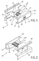
- a device 10 of the inventive arrangement for releasably supporting tubes 40, 41 of a tubular heater, not shown, is shown.
- the device 10 is seen in perspective view from the front and rear. It is constructed from two clamping holders 20, 30.
- the front clamping holder 20 is a cross-sectionally C-shaped metal part, whose base plate forms the front side 21 and whose Side flanges 26, 27 both opposite the mold recesses 24, 24 'have. Starting from the front 21, a through hole 23 is provided centrally in the clamping element 20, in which a clamping screw 11 engages. By means of this clamping screw 11, the front clamping part 20 is connected to the rear clamping part 30.
- the rear clamping part 30 is likewise a metal part. This has to increase the stability of a dome-shaped portion 31, which is bounded to the front by a face plate 39. Centered in the end plate 39, a through hole 33 is introduced for insertion of the clamping screw 11.
- the dome-like section 31 has four walls. Two walls are formed by the top plate 36 and the bottom plate 37 and two further walls are formed by respective side walls. These side walls engage between the top plate 36 and bottom plate 37 and support it.
- the dome-like portion 31 bounded by the four walls forms a receiving space 32 accessible from the rear side, see Fig. 2 , In this receiving space 32, the end of the clamping screw 11 is inserted through the through hole 33.
- This clamping screw 11 is connected at the end to a nut, not shown. This is preferably a square nut, which is held against rotation in the receiving space 32.
- top plate 36 and bottom plate 37 extend in a symmetrical arrangement like a wing.
- the top plate 36 and the bottom plate 37 of the rear clamping element 30 both have mold recesses 34, 34 '.
- the mold recesses 34, 34 'on the top plate 36 and on the bottom plate 37 extend from the free lateral ends of the top plate 36 and bottom plate 37 to the dome-like portion 31, which in this way in case of mounting in contact with the tubes 40, 41st the tubular heater comes. This is better from the FIG. 3 and FIG. 4 to see. It is clear that the clamping elements 20, 30, the tubes 40, 41 in Hold attachment case between them and hold like jaws.
- the clamping connection is achieved by the clamping screw 11, which passes centrally through the clamping elements 20, 30, namely through the through holes 23, 33 and is in communication with the arranged in the receiving space 32 of the clamping element 30 nut.
- the fastening case is achieved when the clamping elements 20, 30 hold the tubes 40, 41 by clamping connection, so that a vertical and axial load does not lead to a detachment of the tubes 40, 41 from the device 10.
- the mounting case is in particular also off Fig. 5 to see.
- the clamping screw 11 is inserted centrally into the clamping element 20 and into the clamping element 30. Starting from the central axis of the clamping screw 11, the clamping elements 20, 30 in the mounting case mirror-symmetrical.
- the dome-like portion 31 engages between the tubes 40, 41 and contacts them at a nip point 35 '(approximately 2 o'clock position relative to tube 40) and at a nip point 35 (approximately 10 o'clock position relative to tube 41).
- the pressure point 35, 35 'in the region of the dome-like portion 31 with the tubes 40, 41 are in the embodiment according to Fig.
- two further contact points 35, 35 ' are provided in the form of recesses 34, 34', namely on the rear side of the tubes 40, 41.
- pinch points 35 ' (approximately at about 11 o'clock position and 1 o'clock position relative to tube 40) and pinch points 35 (approximately at about 11 o'clock position and 1 o'clock position relative to tube 41) is provided.
- the tubes 40, 41 are thus contacted by the clamping element 30 on the top plate 36 and on the lower plate 37 at three pressure points 35 and three pressure points 35 'and opposite of the clamping element 20 at two pressure points 25 and two pressure points 25' of the side flanges 26th , 27.
- This multiple punctiform contact over a wide peripheral region of the tubes 40, 41 with the clamping elements 20, 30 has been found to be particularly advantageous in terms of holding force.
- the clamping elements 20, 30 have the same length in this embodiment.
- the outermost pressure point 25 of the mold recess 24 is opposite to the outer pressure point 35 of the mold recess 34 and the outer pressure point 25 'is opposite to the outer pressure point 35'. This has also been found to be advantageous.
- the device 10 of the inventive arrangement holds both the required axial load, as well as a vertical load by pressure on the tubular heater from above, without the clamping connection for holding the tubes 40, 41 dissolves.
- a bracket 50 to a wall or on a stand.
- a known console 50 shown which consists of two angle parts 51, 52, which are connected via a screw 53 in conjunction.
- the angle part 51 has a slot for a connecting means for attachment to a wall.
- the angle part 52 has a hook 54. Behind these hooks 54 may be provided on the clamping part 30 provided bend 38.
- This bend 38 is best off Fig. 4 to see.
- This bend 38 represents a bend of the lower plate 37 of the clamping element 30.
- Both the upper side 36 and the lower side 37 have an offset, on the one hand for reasons of stability and on the other hand, as described above, for connection to a console 50.
- the invention is not limited to the embodiment shown.
Landscapes
- Engineering & Computer Science (AREA)
- General Engineering & Computer Science (AREA)
- Mechanical Engineering (AREA)
- Physics & Mathematics (AREA)
- Thermal Sciences (AREA)
- Chemical & Material Sciences (AREA)
- Combustion & Propulsion (AREA)
- Clamps And Clips (AREA)
Description
- Die Erfindung betrifft eine Anordnung aus einer Vorrichtung und Röhren zur lösbaren Halterung der Röhren eines Röhrenheizkörpers an einer Konsole, insbesondere einer Wandkonsole oder Standkonsole, gemäß dem Oberbegriff des Anspruchs 1. Eine solche Anordnung ist z.B. aus der
DE 20 2008 008 049 U1 bekannt. - Aus dem Stand der Technik sind verschiedene Vorrichtungen zur Klemmhalterung und Befestigung von Röhrenheizkörpern bekannt. In der Regel werden die vertikalen Röhren von Halterungen klemmend umgriffen und in entsprechende Konsolen eingehängt. Das Gebrauchsmuster
DE 299 20 643 U1 zeigt einen solchen Klemmhalter, bei dem zwei benachbarte Röhren von einem Klemmelement und einer Widerlagerplatte gefasst und mittels einer die beiden Klemmelemente miteinander verbindenden Klemmschraube verspannt sind und so die Röhren mittels einer Klemmverbindung gehalten werden. Nachteilig bei dieser Konstruktion ist, dass bei einem zu starken Anziehen der Klemmschraube sich die Enden der Widerlagerplatte aufbiegen und von den Röhren des Röhrenheizkörpers lösen. Auch eine vertikale Belastung kann zu einer Verformung der Widerlagerplatte führen. Eine andere Klemmkonstruktion für die Röhren zeigt das DokumentDE 20 2008 008 049 U1 . Um hohe Haltekräfte zu erreichen, ist es hier notwendig, zwei schräg zueinander versetzte Wirklinien für die beiden Klemmelemente vorzusehen. - Darüber hinaus sind verbesserte Klemmhalter aufgrund der angekündigten VDE-Vorschriften und TÜV-Normen notwendig, die in Zukunft nur Klemmhalter zulassen, die höhere Haltekräfte bei axialer und vertikaler Belastung aufbringen können.
- Aufgabe der vorliegenden Erfindung ist es daher, einen Klemmhalter zur Verfügung zu stellen, der höhere Prüfbelastungen hinsichtlich der Haltekraft erfüllt.
- Diese Aufgabe wird mittels einer Anordnung aus einer Vorrichtung und Röhren zur lösbaren Halterung der Röhren eines Röhrenheizkörpers an einer Konsole mit den Merkmalen des Anspruchs 1 erfüllt. Diese erfindungsgemäße Anordnung umfasst in bekannter Weise zwei Klemmelemente, die über eine Klemmschraube miteinander in Verbindung stehen, wobei die Klemmschraube durch mittig an den Klemmelementen vorgesehenen Durchgangsbohrungen geführt ist. Beide Klemmelemente besitzen Formausnehmungen, so dass im Befestigungsfall die Röhren des Röhrenheizkörpers zwischen den Klemmelementen im Bereich der Formausnehmungen verspannbar sind. In ähnlicher Weise wie beim Stand der Technik ist die Kontur dieser Formausnehmungen an dem Umfang der Röhren angepasst. Die Klemmelemente liegen jedoch im Befestigungsfall trotz der angepassten Kontur der Formausnehmung nicht mit der Kontur der Formausnehmung an den Röhren des Röhrenheizkörpers linienförmig an, sondern nur punktförmig, da die Formausnehmungen mit Andruckpunkten versehen sind. Diese Andruckpunkte überragen die Kontur der Formausnehmungen und weisen in Richtung der zu haltenden Röhren, so dass beim Verspannen der Röhren zwischen den Klemmelementen diese Andruckpunkte der Formausnehmungen Kontaktpunkte mit den Röhren des Röhrenheizkörpers darstellen. Diese Andruckpunkte können sowohl bei den Formausnehmungen des vorderen Klemmelementes als auch bei den Formausnehmungen des hinteren Klemmelementes vorgesehen sein. Vorteilhafterweise wird bei jeder Formausnehmung am Anfang und Ende der Kontur ein Andruckpunkt vorgesehen.
- Bei einer vorteilhaften Ausführungsform hat zumindest ein Klemmelement mehr als zwei Andruckpunkte und damit Kontaktstellen an den Röhren im Befestigungsfall.
- Bei der erfindungsgemäßen Anordnung wirkt demzufolge die durch die Klemmschraube in die Klemmelemente eingebrachte Klemmkraft nur an wenigen Kontaktpunkten. Dies führt auch bei herstellungsbedingten Toleranzen an den Röhren des Röhrenheizkörpers sowie an den Klemmelementen zu einem sicheren Halt der Röhren des Röhrenheizkörpers. Dieser sichere Halt verhindert ein Verdrehen der erfindungsgemäßen Vorrichtung auch in dem Fall, wo das hintere Klemmelement mit einer Konsole verbunden wird, die sich nicht mittig zwischen zwei Röhren eines Röhrenheizkörpers befindet.
- Die erfindungsgemäße Anordnung zur lösbaren Halterung von Röhren zeigt des Weiteren eine besonders hohe Stabilität, bewirkt durch die besondere Ausgestaltung, insbesondere des hinteren Klemmelements. Dieses hintere Klemmelement besitzt einen nach vorn weisenden domartigen Abschnitt. Dieser wird zum einen durch die Ober- und Unterplatte des hinteren Klemmelementes gebildet, wobei diese beiden Platten beidseitig vom domartigen Abschnitt flügelartig auslaufen und in diesem Bereich an der Vorderseite die Formausnehmung besitzen, d.h. es sind sowohl Formausnehmungen an der Oberplatte als auch an der Unterplatte vorgesehen. Der domartige Abschnitt ist des Weiteren nach vorn durch eine Stirnplatte begrenzt, in der sich mittig die Durchgangsbohrung für die Klemmschraube befindet. Ausgehend von dieser Stirnplatte erstrecken sich links und rechts zwei Seitenwände des domartigen Abschnitts. Diese Seitenwände sind zwischen der Ober- und Unterplatte des Klemmelements angeordnet und stützen damit beide Platten zusätzlich ab.
- Durch den besonderen Aufbau des domartigen Abschnitts ergibt sich an der Rückseite des hinteren Klemmelements in vorteilhafter Weise ein Aufnahmeraum, der von hinten zugänglich ist. Ist die Stirnplatte des domartigen Abschnittes quadratisch, so hat auch dieser Aufnahmeraum einen quadratischen Querschnitt für eine vorzugsweise an den Aufnahmeraum angepasste Mutter. In diese Mutter greift die Klemmschraube ein. Da die Mutter insbesondere verdrehsicher im Aufnahmeraum gehalten werden kann, wird in einfacher Weise eine Schraubverbindung erzielt. Es kann auf diese Weise auf ein Gewinde an dem hinteren Klemmhalter verzichtet werden. Die Stirnplatte des domartigen Abschnitts kann selbstverständlich auch einen anderen Querschnitt besitzen. Auch in diesem Fall kann beispielsweise eine Vierkantmutter im Aufnahmeraum des hinteren Klemmelementes beim Herstellen der Schraubverbindung verdrehsicher gehalten werden.
- Zur Verbindung mit einer Konsole, beispielsweise einer Wandkonsole zur Befestigung des Röhrenheizkörpers an der Wand oder zum Aufstellen des Röhrenheizkörpers unter Benutzung einer Standkonsole, besitzt das hintere Klemmelement entsprechende Verbindungsmittel. Dies kann beispielsweise eine von der Unterplatte ausgehende Abkröpfung sein, die einen Haken bildet, der in eine entsprechende Ausnehmung in der Konsole eingeschoben wird. Es ist jedoch auch möglich, die Oberplatte mit einer entsprechenden Abkröpfung oder Abbiegung zu versehen, die einen Haken zum Einhängen in eine Konsole bildet. Zusätzlich erhöhen die Abkröpfungen an der Ober- und Unterplatte die Stabilität des hinteren Klemmelements.
- Ein solches Klemmelement lässt sich in bekannter Weise leicht an einem Röhrenheizkörper montieren, indem ein Klemmelement aus seiner horizontalen Ausrichtung um die Mittelachse der Klemmschraube herum in eine vertikale Ausrichtung gedreht wird und so leicht zwischen den Röhren des Röhrenheizkörpers hindurch gesteckt werden kann. Befindet sich das Klemmelement hinter den Röhren wird es wieder zurückgedreht und die Klemmschraube angezogen bis der Befestigungsfall, also ein sicheres Verklemmen der Röhren zwischen den beiden Klemmelementen erzielt ist. Im Befestigungsfall greift der domartige Abschnitt des hinteren Klemmelements zwischen zwei Röhren des Röhrenheizkörpers. Da die Formausnehmungen am hinteren Klemmelement bis zum domartigen Abschnitt reichen, berührt der domartigen Abschnitt im Befestigungsfall seitlich jeweils eine Röhre. Bei einer besonders vorteilhaften Ausführungsform ist vorgesehen, dass sich im Bereich des domartigen Abschnitts ein Andruckpunkt der Formausnehmung befindet. Bei einer solchen Ausführungsform wird ein weiterer Andruckpunkt der Formausnehmungen des hinteren Klemmelements so vorgesehen, dass die Kontaktstelle sich an der Rückseite der Röhren befindet, so dass die Röhre zweiseitig gefasst wird. Dabei kann es sich um eine oder mehrere weitere Kontaktstellen handeln. Darüber hinaus ist es vorteilhaft, auch entsprechende Andruckpunkte in den Formausnehmungen des vorderen Klemmelements vorzusehen.
- Bei dem vorderen Klemmelement handelt es sich vorzugsweise um ein im Querschnitt C-förmiges Metallteil, nämlich einer Grundplatte, welche die Vorderseite bildet und von der zwei senkrechte Seitenflansche abragen. Diese Seitenflansche besitzen die Formausnehmung, d.h. sowohl am oberen als auch am unteren Seitenflansch ist je eine Formausnehmung vorgesehen. Mittig durch die Grundplatte führt die Durchgangsbohrung für die Klemmschraube.
- Das vordere Klemmelement lässt sich in einfacher Weise aus einer Metallplatte herstellen. In die Metallplatte werden die Durchgangsbohrung und gewünschten Formausnehmungen eingestanzt und dann die Seitenflansche durch Abbiegen von der Grundplatte erzeugt. Auch das hintere Klemmelement lässt sich in einfacher Weise aus einer Metallplatte fertigen. In diese Metallplatte werden die entsprechenden Ausnehmungen eingestanzt. Ausgehend von der Stirnplatte werden durch senkrechtes Abbiegen die Oberplatte, die Unterplatte und die Seitenwände des domartigen Abschnitts erzeugt, ebenso werden die Abkröpfung an der Oberplatte und Unterplatte durch Abbiegen leicht erhalten. Für die erfindungsgemäße Anordnung, insbesondere die Klemmelemente, ist ein geringer Materialeinsatz und auch ein geringer Fertigungsaufwand notwendig. Die Vorrichtung ist einfach aufgebaut, nämlich aus den zwei Klemmelementen, der Klemmschraube, der Mutter und bedarfsweise auch einem Federelement, welches über die Klemmmutter geschoben und zwischen den Klemmelementen angeordnet ist. Dieses Federelement dient bei der Demontage als Rückstellfeder, um die Klemmelemente leichter von den Röhren zu lösen. Trotz des einfachen Aufbaus dieser erfindungsgemäßen Anordnung weist diese eine sehr hohe Stabilität auf, die gegenüber bekannten Klemmhaltern höhere Prüfbelastungen bzgl. der Haltekräfte erfüllt.
- Nachfolgend wird die Erfindung anhand von Zeichnungen an einem Ausführungsbeispiel näher beschrieben. Es zeigen:
- Fig. 1
- eine perspektivische Ansicht der Vorrichtung der erfindungsgemäßen Anordnung von vorn,
- Fig. 2
- eine perspektivische Ansicht der Vorrichtung von
Fig. 1 von hinten, - Fig. 3
- eine perspektivische Ansicht der Vorrichtung der erfindungsgemäßen Anordnung von
Fig. 1 im Befestigungsfall von vorn, - Fig. 4
- eine perspektivische Ansicht der Vorrichtung der erfindungsgemäßen Anordnung von
Fig. 1 im Befestigungsfall von hinten, - Fig. 5
- eine Draufsicht auf die Vorrichtung der erfindungsgemäßen Anordnung gemäß
Fig. 1 im Befestigungsfall, - Fig. 6
- eine Konsole.
- In den
Fig. 1 bis 5 ist eine Vorrichtung 10 der erfindungsgemäßen Anordnung zur lösbaren Halterung von Röhren 40, 41 eines nicht gezeigten Röhrenheizkörpers gezeigt. In denFig. 1 und 2 ist die Vorrichtung 10 in perspektivischer Ansicht von vorn und hinten zu sehen. Sie ist aufgebaut aus zwei Klemmhaltern 20, 30. Der vordere Klemmhalter 20 ist ein im Querschnitt C-förmiges Metallteil, dessen Grundplatte die Vorderseite 21 bildet und dessen Seitenflansche 26, 27 beide gegenüberliegend die Formausnehmungen 24, 24' besitzen. Ausgehend von der Vorderseite 21 ist mittig im Klemmelement 20 eine Durchgangsbohrung 23 vorgesehen, in die eine Klemmschraube 11 eingreift. Mittels dieser Klemmschraube 11 ist das vordere Klemmteil 20 mit dem hinteren Klemmteil 30 verbunden. - Bei dem hinteren Klemmteil 30 handelt es sich ebenfalls um ein Metallteil. Dieses besitzt zur Erhöhung der Stabilität einen domartigen Abschnitt 31, der nach vorn durch eine Stirnplatte 39 begrenzt wird. Mittig in die Stirnplatte 39 ist zum Einführen der Klemmschraube 11 eine Durchgangsbohrung 33 eingebracht. Ausgehend von dieser Stirnplatte 39 besitzt der domartige Abschnitt 31 vier Wände. Zwei Wände werden durch die Oberplatte 36 und die Unterplatte 37 und zwei weitere Wände werden durch entsprechende Seitenwände gebildet. Diese Seitenwände greifen zwischen die Oberplatte 36 und Unterplatte 37 ein und stützen diese ab. Der domartige Abschnitt 31, der durch die vier Wände begrenzt ist, bildet einen von der Rückseite zugänglichen Aufnahmeraum 32, siehe
Fig. 2 . In diesen Aufnahmeraum 32 ist das Ende der Klemmschraube 11 durch die Durchgangsbohrung 33 eingeführt. Diese Klemmschraube 11 ist endseitig mit einer nicht gezeigten Mutter verbunden. Hierbei handelt es sich vorzugsweise um eine Vierkantmutter, die verdrehsicher in dem Aufnahmeraum 32 gehalten wird. - Beidseitig vom domartigen Abschnitt 31 erstrecken sich in symmetrischer Anordnung flügelartig die Oberplatte 36 und Unterplatte 37. Die Oberplatte 36 und die Unterplatte 37 des hinteren Klemmelements 30 besitzen beide Formausnehmungen 34, 34'. Die Formausnehmungen 34, 34' an der Oberplatte 36 und an der Unterplatte 37 erstrecken sich ausgehend von den freien seitlichen Enden der Oberplatte 36 und Unterplatte 37 bis hin zum domartigen Abschnitt 31, der auf diese Weise im Befestigungsfall in Berührung mit den Röhren 40, 41 des Röhrenheizkörpers kommt. Dies ist besser aus den
Fig. 3 und Fig. 4 zu ersehen. Deutlich wird, dass die Klemmelemente 20, 30 die Röhren 40, 41 im Befestigungsfall zwischen sich aufnehmen und wie Klemmbacken halten. Die Klemmverbindung wird durch die Klemmschraube 11 erzielt, die mittig durch die Klemmelemente 20, 30, nämlich durch die Durchgangsbohrungen 23, 33 geht und in Verbindung mit der im Aufnahmeraum 32 des Klemmelements 30 angeordneten Mutter steht. Durch das Einschrauben dieser Klemmschraube 11 wird eine Klemmkraft erzeugt, die im Befestigungsfall eine stabile Halterung der Röhren 40, 41 in der erfindungsgemäßen Vorrichtung ermöglicht. Der Befestigungsfall ist erreicht, wenn die Klemmelemente 20, 30 die Röhren 40, 41 durch Klemmverbindung halten, so dass eine vertikale und axiale Belastung nicht zu einem Herauslösen der Röhren 40, 41 aus der Vorrichtung 10 führt. - Der Befestigungsfall ist insbesondere auch aus
Fig. 5 zu ersehen. Die Klemmschraube 11 ist mittig in das Klemmelement 20 und in das Klemmelement 30 eingeführt. Ausgehend von der Mittelachse der Klemmschraube 11 sind die Klemmelemente 20, 30 im Befestigungsfall spiegelsymmetrisch. Der domartige Abschnitt 31 greift zwischen die Röhren 40, 41 und berührt diese in einem Andruckpunkt 35' (in etwa 2 Uhr-Stellung bezogen auf Röhre 40) und in einem Andruckpunkt 35 (in etwa 10 Uhr-Stellung bezogen auf Röhre 41). - Diese Andruckpunkte 35, 35' sind Teil der Formausnehmung 34, 34'. Diese Formausnehmungen 34, 34' sind an den Umfang und die Kontur der Röhren 40, 41 angepasst. Bei anderen Querschnitten und Umfangslinien der Röhren 40, 41 werden andere Konturen für die Formausnehmungen 34, 34' des Klemmelements 30 ausgewählt. An dieser Kontur für die Formausnehmung 34, 34' sind Andruckpunkte 35, 35' vorgesehen. Diese Andruckpunkte 35, 35' der Formausnehmung 34, 34'stellen kleine konvexe Ausbauchungen herausragend aus der passend zum Umfang der Röhre 40 vorgesehene Konturlinie dar. Neben dem Andruckpunkt 35, 35' im Bereich des domartigen Abschnitts 31 mit den Röhren 40, 41 sind im Ausführungsbeispiel gemäß
Fig. 5 bei den Formausnehmungen 34, 34' zwei weitere Andruckpunkte 35, 35' vorgesehen, nämlich an der Rückseite der Röhren 40, 41. Betrachtet manFig. 5 , so sind weitere Andruckpunkte 35' (in etwa in etwa 11-Uhr-Stellung und 1-Uhr-Stellung bezogen auf Röhre 40) und Andruckpunkte 35 (in etwa in etwa 11-Uhr-Stellung und 1-Uhr-Stellung bezogen auf Röhre 41) vorgesehen. Die Röhren 40, 41 werden damit durch das Klemmelement 30 an der Oberplatte 36 und an der Unterplatte 37 jeweils an drei Andruckpunkten 35 und an drei Andruckpunkten 35' kontaktiert und gegenüberliegend vom Klemmelements 20 an jeweils zwei Andruckpunkten 25 und zwei Andruckpunkte 25' der Seitenflansche 26, 27. Dieser mehrfache punktförmige Kontakt über einen weiten Umfangsbereich der Röhren 40, 41 mit den Klemmelementen 20, 30 hat sich als besonders vorteilhaft hinsichtlich der Haltekraft herausgestellt. - Die Klemmelemente 20, 30 besitzen in diesem Ausführungsbeispiel die gleiche Länge. Der äußerste Andruckpunkt 25 der Formausnehmung 24 ist gegenüberliegend zum äußeren Andruckpunkt 35 der Formausnehmung 34 und der äußere Andruckpunkt 25' ist gegenüberliegend zum äußeren Andruckpunkt 35'. Dies hat sich zusätzlich als vorteilhaft herausgestellt.
- Die Vorrichtung 10 der erfindungsgemäßen Anordnung hält sowohl die geforderte axiale Belastung, als auch eine vertikaler Belastung durch Druck auf den Röhrenheizkörper von oben aus, ohne dass sich die Klemmverbindung zur Halterung der Röhren 40, 41 löst.
- Ist die Vorrichtung 10 mit dem Röhrenheizkörper verbunden, d.h. die Röhre 40, 41 zwischen den Klemmhaltern 20, 30 verklemmt, so kann der Röhrenheizkörper mittels einer Konsole 50 an einer Wand oder an einem Standfuß befestigt werden. In
Fig. 6 ist beispielsweise eine bekannte Konsole 50 gezeigt, die aus zwei Winkelteilen 51, 52 besteht, die über eine Schraube 53 in Verbindung stehen. Das Winkelteil 51 besitzt ein Langloch für ein Verbindungsmittel zur Befestigung an einer Wand. Der Winkelteil 52 besitzt einen Haken 54. Hinter diesen Haken 54 kann eine am Klemmteil 30 vorgesehene Abkröpfung 38 eingreifen. Diese Abkröpfung 38 ist am besten ausFig. 4 zu ersehen. Diese Abkröpfung 38 stellt eine Abbiegung der Unterplatte 37 des Klemmelements 30 dar. Sowohl die Oberseite 36 als auch die Unterseite 37 besitzen eine Abkröpfung, zum einen aus Stabilitätsgründen und zum anderen, wie vorbeschrieben, zur Verbindung mit einer Konsole 50. - Zur Montage eines Röhrenheizkörpers werden je nach Größe des Röhrenheizkörpers auch mehrere Vorrichtungen 10 eingesetzt. Die Vorrichtung 10 kann in einfacher Weise montiert und demontiert werden, da die Klemmhalter 20, 30 durch die Klemmschraube 11 vor und nach der Montage um die Mittelachse M der Klemmschraube 11 drehbeweglich sind, so dass ein Klemmelement 20 oder 30 zwischen den Röhren 40, 41 in vertikaler Ausrichtung durchgeschoben und anschließend wieder in vertikaler Ausrichtung gebracht werden kann. Für eine entsprechende Befestigung und in gleicher Weise bei der Demontage wird die Klemmschraube 11 gelöst und damit die Klemmelemente 20, 30 voneinander entfernt werden. Dieser Vorgang wird durch ein zwischen den Klemmelementen 20, 30 vorgesehenes Federelement 12 unterstützt.
- Der Erfindung ist nicht auf das gezeigte Ausführungsbeispiel beschränkt.
-
- 10
- Vorrichtung
- 11
- Klemmschraube
- 12
- Federelement
- 20
- Klemmelement, vordere
- 21
- Vorderseite
- 22
- Rückseite
- 23
- Durchgangsbohrung
- 24, 24'
- Formausnehmung
- 25, 25'
- Andruckpunkte
- 26
- Seitenflansch
- 27
- Seitenflansch
- 28
- Grundplatte
- 30
- Klemmelement, hintere
- 31
- domartiger Abschnitt
- 32
- Aufnahmeraum
- 33
- Durchgangsbohrung
- 34, 34'
- Formausnehmung
- 35, 35'
- Andruckpunkte
- 36
- Oberplatte
- 37
- Unterplatte
- 38
- Abkröpfung
- 39
- Stirnplatte
- 40
- Röhre
- 41
- Röhre
- 50
- Konsole
- 51
- Winkelteil
- 52
- Winkelteil
- 53
- Schraube
- 54
- Haken
- M
- Mittelachse
Claims (10)
- Anordnung aus einer Vorrichtung (10) und Röhren (40, 41) zur lösbaren Halterung der Röhren (40, 41) eines Röhrenheizkörpers an einer Konsole (50),
mit zwei Klemmelementen (20, 30), die über eine Klemmschraube (11) miteinander in Verbindung stehen, wobei die Klemmschraube (11) durch mittig an den Klemmelementen (20, 30) vorgesehenen Durchgangsbohrungen (23, 33) geführt ist,
wobei das vordere Klemmelement (20) mindestens zwei Formausnehmungen (24, 24') und das hintere Klemmelement (30) mindestens zwei Formausnehmungen (34, 34') besitzt und im Befestigungsfall zur Halterung eines Röhrenheizkörpers die Röhren (40, 41) zwischen den Klemmelementen (20, 30) im Bereich der Formausnehmungen (24, 34; 24', 34') verspannbar sind,
wobei die Formausnehmungen (24, 34; 24', 34') eine an den Umfang der Röhren (40, 41) angepasste Kontur aufweisen,
dadurch gekennzeichnet, dass
die Formausnehmungen (24, 24; 34, 34') zumindest eines Klemmelements (20, 30) mit Andruckpunkten (25, 25'; 35, 35') versehen sind, welche die Kontur der Formausnehmungen (24, 34; 24', 34') in Richtung der zu haltenden Röhren (40, 41) überragen. - Anordnung nach Anspruch 1, dadurch gekennzeichnet, dass 2 bis 3 Andruckpunkte (25, 25'; 35, 35') je Formausnehmung (24, 24; 34, 34') vorgesehen sind.
- Anordnung nach Anspruch 1 oder 2, dadurch gekennzeichnet, dass das hintere Klemmelement (30) einen nach vorn weisenden domartigen Abschnitt (31) aufweist, der im Befestigungsfall zwischen die Röhren (40, 41) greift, wobei der domartige Abschnitt (31) seitlich durch die Formausnehmungen (34, 34') begrenzt ist.
- Anordnung nach Anspruch 3, dadurch gekennzeichnet, dass durch eine vordere Stirnplatte (39) des domartigen Abschnitts (31) die Durchgangsbohrung (33) für die Klemmschraube (11) verläuft.
- Anordnung nach Anspruch 4, dadurch gekennzeichnet, dass der domartige Abschnitt (31) durch die Stirnplatte (39), durch Abschnitte der Oberseite (36) sowie Unterseite (37) des hinteren Klemmelementes (30) und durch zwei Seitenwände gebildet ist, so dass sich auf der Rückseite des hinteren Klemmelementes (30) ein nur rückseitig geöffneter Aufnahmeraum (32) für eine mit der Klemmschraube (11) zusammenwirkenden Mutter ergibt, vorzugsweise ein im Querschnitt rechteckiger Aufnahmeraum (32) für eine Vierkantmutter.
- Anordnung nach einem der Ansprüche 1 bis 5, dadurch gekennzeichnet, dass die Oberseite (36) und die Unterseite (37) des hinteren Klemmelementes (30) an ihrem freien Ende senkrecht abgekröpft sind, wobei vorzugsweise eine Abkröpfung (38) der Verbindung mit einer Konsole (50) dient.
- Anordnung mit einer Konsole und einer Anordnung nach Anspruch 6, dadurch gekennzeichnet, dass mittels einer Konsole (50) eine Befestigung an einer Wand oder an einem Standfuß realisierbar ist.
- Anordnung nach Anspruch 1, dadurch gekennzeichnet, dass das vordere Klemmelement (20) einen C-förmigen Querschnitt aufweist, nämlich eine Grundplatte (28) mit zwei senkrecht abragenden Seitenflanschen (26, 27) besitzt, wobei in die Seitenflansche (26, 27) die Formausnehmungen (24, 24') eingeformt sind.
- Anordnung nach Anspruch 1, dadurch gekennzeichnet, dass zur leichteren Demontage zwischen den Klemmelementen (20, 30) ein Federelement (12) angeordnet ist.
- Anordnung nach Anspruch 1, dadurch gekennzeichnet, dass die Klemmelemente (20, 30) aus Metall bestehen und durch Stanzen sowie Biegen hergestellt sind.
Applications Claiming Priority (1)
| Application Number | Priority Date | Filing Date | Title |
|---|---|---|---|
| DE202009011545U DE202009011545U1 (de) | 2009-08-25 | 2009-08-25 | Vorrichtung zur lösbaren Halterung von Röhren eines Röhrenheizkörpers |
Publications (3)
| Publication Number | Publication Date |
|---|---|
| EP2295874A2 EP2295874A2 (de) | 2011-03-16 |
| EP2295874A3 EP2295874A3 (de) | 2013-11-27 |
| EP2295874B1 true EP2295874B1 (de) | 2016-06-08 |
Family
ID=41462079
Family Applications (1)
| Application Number | Title | Priority Date | Filing Date |
|---|---|---|---|
| EP10008410.2A Active EP2295874B1 (de) | 2009-08-25 | 2010-08-12 | Anordnung aus einer Vorrichtung und Röhren zur lösbaren Halterung der Röhren eines Röhrenheizkörpers |
Country Status (4)
| Country | Link |
|---|---|
| EP (1) | EP2295874B1 (de) |
| DE (1) | DE202009011545U1 (de) |
| HU (1) | HUE029486T2 (de) |
| PL (1) | PL2295874T3 (de) |
Families Citing this family (2)
| Publication number | Priority date | Publication date | Assignee | Title |
|---|---|---|---|---|
| CN111236154A (zh) * | 2020-03-05 | 2020-06-05 | 四川鼎恒建设工程有限公司 | 一种水利工程用止水带固定装置及止水带安装方法 |
| CN111237548B (zh) * | 2020-03-17 | 2022-02-11 | 上海三一重机股份有限公司 | 管类固定装置 |
Family Cites Families (7)
| Publication number | Priority date | Publication date | Assignee | Title |
|---|---|---|---|---|
| DE2255166A1 (de) * | 1972-11-10 | 1974-05-16 | Hilti Ag | Heizkoerperhalter |
| FR2247682A1 (en) * | 1973-10-12 | 1975-05-09 | Mueller Franz | Radiator support for adjacent radiator sections - has internal socket in clamping bolt head receiving tool |
| DE29920643U1 (de) | 1999-11-25 | 2000-02-17 | Helmut Pütz GmbH, 51145 Köln | Klemmhalter für die Befestigung eines Röhrenradiators |
| DE20019146U1 (de) * | 2000-11-10 | 2001-01-11 | Zehnder Verkaufs- und Verwaltungs-AG, Gränichen | Haltevorrichtung zur Wandbefestigung eines Röhrenradiators |
| DE202008004548U1 (de) * | 2008-03-28 | 2008-08-14 | Kermi Gmbh | Haltevorrichtung für Röhrenheizkörper |
| DE202008008049U1 (de) * | 2008-06-18 | 2008-09-04 | Kermi Gmbh | Vorrichtung zur klemmenden Halterung und Befestigung von Rohrheizkörpern |
| DE202008008050U1 (de) * | 2008-06-18 | 2008-09-11 | Kermi Gmbh | Vorrichtung zur klemmenden Halterung und Befestigung von Rohrheizkörpern |
-
2009
- 2009-08-25 DE DE202009011545U patent/DE202009011545U1/de not_active Expired - Lifetime
-
2010
- 2010-08-12 EP EP10008410.2A patent/EP2295874B1/de active Active
- 2010-08-12 HU HUE10008410A patent/HUE029486T2/hu unknown
- 2010-08-12 PL PL10008410.2T patent/PL2295874T3/pl unknown
Also Published As
| Publication number | Publication date |
|---|---|
| DE202009011545U1 (de) | 2009-12-31 |
| EP2295874A3 (de) | 2013-11-27 |
| EP2295874A2 (de) | 2011-03-16 |
| PL2295874T3 (pl) | 2016-12-30 |
| HUE029486T2 (hu) | 2017-02-28 |
Similar Documents
| Publication | Publication Date | Title |
|---|---|---|
| EP1987213B1 (de) | Deckenschalungssystem | |
| EP3303851B1 (de) | Vorrichtung zum halten eines bauteils | |
| EP2091312B2 (de) | Anreihbares Elektronikgehäuse mit Stift- oder Buchsenleisten | |
| DE202017102147U1 (de) | Leitungsdurchführung, insbesondere Zugentlastung für eine Energieführungskette | |
| WO2017036439A1 (de) | Halterahmen für steckverbindermodule | |
| DE1465318B2 (de) | Elektrischer klemmenblock | |
| DE102005031152A1 (de) | Deckenschalungssystem | |
| EP2295874B1 (de) | Anordnung aus einer Vorrichtung und Röhren zur lösbaren Halterung der Röhren eines Röhrenheizkörpers | |
| DE102007011986A1 (de) | Anzeigevorrichtung mit Halteelement | |
| DE19736565C2 (de) | Verbindungsvorrichtung | |
| DE883465C (de) | Befestigungseinrichtung fuer elektrische Geraete u. dgl. | |
| EP0724104A1 (de) | Zugentlastungs- und Befestigungselement | |
| EP3461963B1 (de) | Trägersystem und system von verbindungselementen zur verbindung von trägern | |
| AT390485B (de) | Einrichtung zur kupplung von zwei zueinander in einem winkel befindlichen elementen | |
| DE102008015374B4 (de) | Elektrische Klemme | |
| EP3772778B1 (de) | Trägersystem zur befestigung eines länglichen gegenstands sowie spangenaufsatz | |
| EP0874423A2 (de) | Tragvorrichtung für eine Stromschiene, Stromschiene und Kupplungsvorrichtung hierfür | |
| EP1785550B1 (de) | Verbindungseinrichtung | |
| DE102018107886B4 (de) | Steckverbindersystem mit einem bistabilen Element | |
| DE10328406B4 (de) | Schaltschrank insbesondere für Niederspannungsschaltanlagen | |
| DE638445C (de) | Zughebel fuer elektrische Drehschalter | |
| DE10252297A1 (de) | Abstand- und Distanzhalter | |
| EP0730836A1 (de) | Gardinengleiter | |
| DE29905254U1 (de) | Gepäckhalterung, insbesondere für Fahrräder | |
| EP2905799A1 (de) | Anordnung aus einem Basisgerät und einem Anbaugerät |
Legal Events
| Date | Code | Title | Description |
|---|---|---|---|
| PUAI | Public reference made under article 153(3) epc to a published international application that has entered the european phase |
Free format text: ORIGINAL CODE: 0009012 |
|
| AK | Designated contracting states |
Kind code of ref document: A2 Designated state(s): AL AT BE BG CH CY CZ DE DK EE ES FI FR GB GR HR HU IE IS IT LI LT LU LV MC MK MT NL NO PL PT RO SE SI SK SM TR |
|
| AX | Request for extension of the european patent |
Extension state: BA ME RS |
|
| PUAL | Search report despatched |
Free format text: ORIGINAL CODE: 0009013 |
|
| AK | Designated contracting states |
Kind code of ref document: A3 Designated state(s): AL AT BE BG CH CY CZ DE DK EE ES FI FR GB GR HR HU IE IS IT LI LT LU LV MC MK MT NL NO PL PT RO SE SI SK SM TR |
|
| AX | Request for extension of the european patent |
Extension state: BA ME RS |
|
| RIC1 | Information provided on ipc code assigned before grant |
Ipc: F24D 19/02 20060101AFI20131024BHEP Ipc: F16L 3/237 20060101ALI20131024BHEP |
|
| 17P | Request for examination filed |
Effective date: 20140503 |
|
| RBV | Designated contracting states (corrected) |
Designated state(s): AL AT BE BG CH CY CZ DE DK EE ES FI FR GB GR HR HU IE IS IT LI LT LU LV MC MK MT NL NO PL PT RO SE SI SK SM TR |
|
| 17Q | First examination report despatched |
Effective date: 20150625 |
|
| GRAP | Despatch of communication of intention to grant a patent |
Free format text: ORIGINAL CODE: EPIDOSNIGR1 |
|
| INTG | Intention to grant announced |
Effective date: 20160218 |
|
| GRAS | Grant fee paid |
Free format text: ORIGINAL CODE: EPIDOSNIGR3 |
|
| GRAA | (expected) grant |
Free format text: ORIGINAL CODE: 0009210 |
|
| AK | Designated contracting states |
Kind code of ref document: B1 Designated state(s): AL AT BE BG CH CY CZ DE DK EE ES FI FR GB GR HR HU IE IS IT LI LT LU LV MC MK MT NL NO PL PT RO SE SI SK SM TR |
|
| REG | Reference to a national code |
Ref country code: GB Ref legal event code: FG4D Free format text: NOT ENGLISH |
|
| REG | Reference to a national code |
Ref country code: CH Ref legal event code: EP |
|
| REG | Reference to a national code |
Ref country code: IE Ref legal event code: FG4D Free format text: LANGUAGE OF EP DOCUMENT: GERMAN |
|
| REG | Reference to a national code |
Ref country code: AT Ref legal event code: REF Ref document number: 805531 Country of ref document: AT Kind code of ref document: T Effective date: 20160715 |
|
| REG | Reference to a national code |
Ref country code: DE Ref legal event code: R096 Ref document number: 502010011795 Country of ref document: DE |
|
| REG | Reference to a national code |
Ref country code: LT Ref legal event code: MG4D |
|
| REG | Reference to a national code |
Ref country code: NL Ref legal event code: MP Effective date: 20160608 |
|
| PG25 | Lapsed in a contracting state [announced via postgrant information from national office to epo] |
Ref country code: LT Free format text: LAPSE BECAUSE OF FAILURE TO SUBMIT A TRANSLATION OF THE DESCRIPTION OR TO PAY THE FEE WITHIN THE PRESCRIBED TIME-LIMIT Effective date: 20160608 Ref country code: FI Free format text: LAPSE BECAUSE OF FAILURE TO SUBMIT A TRANSLATION OF THE DESCRIPTION OR TO PAY THE FEE WITHIN THE PRESCRIBED TIME-LIMIT Effective date: 20160608 Ref country code: NO Free format text: LAPSE BECAUSE OF FAILURE TO SUBMIT A TRANSLATION OF THE DESCRIPTION OR TO PAY THE FEE WITHIN THE PRESCRIBED TIME-LIMIT Effective date: 20160908 |
|
| PG25 | Lapsed in a contracting state [announced via postgrant information from national office to epo] |
Ref country code: ES Free format text: LAPSE BECAUSE OF FAILURE TO SUBMIT A TRANSLATION OF THE DESCRIPTION OR TO PAY THE FEE WITHIN THE PRESCRIBED TIME-LIMIT Effective date: 20160608 Ref country code: GR Free format text: LAPSE BECAUSE OF FAILURE TO SUBMIT A TRANSLATION OF THE DESCRIPTION OR TO PAY THE FEE WITHIN THE PRESCRIBED TIME-LIMIT Effective date: 20160909 Ref country code: SE Free format text: LAPSE BECAUSE OF FAILURE TO SUBMIT A TRANSLATION OF THE DESCRIPTION OR TO PAY THE FEE WITHIN THE PRESCRIBED TIME-LIMIT Effective date: 20160608 Ref country code: LV Free format text: LAPSE BECAUSE OF FAILURE TO SUBMIT A TRANSLATION OF THE DESCRIPTION OR TO PAY THE FEE WITHIN THE PRESCRIBED TIME-LIMIT Effective date: 20160608 Ref country code: NL Free format text: LAPSE BECAUSE OF FAILURE TO SUBMIT A TRANSLATION OF THE DESCRIPTION OR TO PAY THE FEE WITHIN THE PRESCRIBED TIME-LIMIT Effective date: 20160608 |
|
| PG25 | Lapsed in a contracting state [announced via postgrant information from national office to epo] |
Ref country code: BE Free format text: LAPSE BECAUSE OF NON-PAYMENT OF DUE FEES Effective date: 20160831 |
|
| PG25 | Lapsed in a contracting state [announced via postgrant information from national office to epo] |
Ref country code: RO Free format text: LAPSE BECAUSE OF FAILURE TO SUBMIT A TRANSLATION OF THE DESCRIPTION OR TO PAY THE FEE WITHIN THE PRESCRIBED TIME-LIMIT Effective date: 20160608 Ref country code: EE Free format text: LAPSE BECAUSE OF FAILURE TO SUBMIT A TRANSLATION OF THE DESCRIPTION OR TO PAY THE FEE WITHIN THE PRESCRIBED TIME-LIMIT Effective date: 20160608 Ref country code: IT Free format text: LAPSE BECAUSE OF FAILURE TO SUBMIT A TRANSLATION OF THE DESCRIPTION OR TO PAY THE FEE WITHIN THE PRESCRIBED TIME-LIMIT Effective date: 20160608 Ref country code: SK Free format text: LAPSE BECAUSE OF FAILURE TO SUBMIT A TRANSLATION OF THE DESCRIPTION OR TO PAY THE FEE WITHIN THE PRESCRIBED TIME-LIMIT Effective date: 20160608 Ref country code: IS Free format text: LAPSE BECAUSE OF FAILURE TO SUBMIT A TRANSLATION OF THE DESCRIPTION OR TO PAY THE FEE WITHIN THE PRESCRIBED TIME-LIMIT Effective date: 20161008 |
|
| PG25 | Lapsed in a contracting state [announced via postgrant information from national office to epo] |
Ref country code: SM Free format text: LAPSE BECAUSE OF FAILURE TO SUBMIT A TRANSLATION OF THE DESCRIPTION OR TO PAY THE FEE WITHIN THE PRESCRIBED TIME-LIMIT Effective date: 20160608 Ref country code: PT Free format text: LAPSE BECAUSE OF FAILURE TO SUBMIT A TRANSLATION OF THE DESCRIPTION OR TO PAY THE FEE WITHIN THE PRESCRIBED TIME-LIMIT Effective date: 20161010 |
|
| REG | Reference to a national code |
Ref country code: HU Ref legal event code: AG4A Ref document number: E029486 Country of ref document: HU |
|
| REG | Reference to a national code |
Ref country code: DE Ref legal event code: R097 Ref document number: 502010011795 Country of ref document: DE |
|
| PG25 | Lapsed in a contracting state [announced via postgrant information from national office to epo] |
Ref country code: MC Free format text: LAPSE BECAUSE OF FAILURE TO SUBMIT A TRANSLATION OF THE DESCRIPTION OR TO PAY THE FEE WITHIN THE PRESCRIBED TIME-LIMIT Effective date: 20160608 |
|
| REG | Reference to a national code |
Ref country code: CH Ref legal event code: PL |
|
| PLBE | No opposition filed within time limit |
Free format text: ORIGINAL CODE: 0009261 |
|
| STAA | Information on the status of an ep patent application or granted ep patent |
Free format text: STATUS: NO OPPOSITION FILED WITHIN TIME LIMIT |
|
| PG25 | Lapsed in a contracting state [announced via postgrant information from national office to epo] |
Ref country code: LI Free format text: LAPSE BECAUSE OF NON-PAYMENT OF DUE FEES Effective date: 20160831 Ref country code: CH Free format text: LAPSE BECAUSE OF NON-PAYMENT OF DUE FEES Effective date: 20160831 |
|
| 26N | No opposition filed |
Effective date: 20170309 |
|
| GBPC | Gb: european patent ceased through non-payment of renewal fee |
Effective date: 20160908 |
|
| REG | Reference to a national code |
Ref country code: FR Ref legal event code: ST Effective date: 20170428 |
|
| PG25 | Lapsed in a contracting state [announced via postgrant information from national office to epo] |
Ref country code: SI Free format text: LAPSE BECAUSE OF FAILURE TO SUBMIT A TRANSLATION OF THE DESCRIPTION OR TO PAY THE FEE WITHIN THE PRESCRIBED TIME-LIMIT Effective date: 20160608 Ref country code: DK Free format text: LAPSE BECAUSE OF FAILURE TO SUBMIT A TRANSLATION OF THE DESCRIPTION OR TO PAY THE FEE WITHIN THE PRESCRIBED TIME-LIMIT Effective date: 20160608 |
|
| REG | Reference to a national code |
Ref country code: IE Ref legal event code: MM4A |
|
| PG25 | Lapsed in a contracting state [announced via postgrant information from national office to epo] |
Ref country code: FR Free format text: LAPSE BECAUSE OF NON-PAYMENT OF DUE FEES Effective date: 20160831 Ref country code: GB Free format text: LAPSE BECAUSE OF NON-PAYMENT OF DUE FEES Effective date: 20160908 Ref country code: IE Free format text: LAPSE BECAUSE OF NON-PAYMENT OF DUE FEES Effective date: 20160812 |
|
| PG25 | Lapsed in a contracting state [announced via postgrant information from national office to epo] |
Ref country code: LU Free format text: LAPSE BECAUSE OF NON-PAYMENT OF DUE FEES Effective date: 20160812 |
|
| PG25 | Lapsed in a contracting state [announced via postgrant information from national office to epo] |
Ref country code: CY Free format text: LAPSE BECAUSE OF FAILURE TO SUBMIT A TRANSLATION OF THE DESCRIPTION OR TO PAY THE FEE WITHIN THE PRESCRIBED TIME-LIMIT Effective date: 20160608 |
|
| PG25 | Lapsed in a contracting state [announced via postgrant information from national office to epo] |
Ref country code: MT Free format text: LAPSE BECAUSE OF FAILURE TO SUBMIT A TRANSLATION OF THE DESCRIPTION OR TO PAY THE FEE WITHIN THE PRESCRIBED TIME-LIMIT Effective date: 20160608 Ref country code: TR Free format text: LAPSE BECAUSE OF FAILURE TO SUBMIT A TRANSLATION OF THE DESCRIPTION OR TO PAY THE FEE WITHIN THE PRESCRIBED TIME-LIMIT Effective date: 20160608 Ref country code: HR Free format text: LAPSE BECAUSE OF FAILURE TO SUBMIT A TRANSLATION OF THE DESCRIPTION OR TO PAY THE FEE WITHIN THE PRESCRIBED TIME-LIMIT Effective date: 20160608 Ref country code: MK Free format text: LAPSE BECAUSE OF FAILURE TO SUBMIT A TRANSLATION OF THE DESCRIPTION OR TO PAY THE FEE WITHIN THE PRESCRIBED TIME-LIMIT Effective date: 20160608 |
|
| PG25 | Lapsed in a contracting state [announced via postgrant information from national office to epo] |
Ref country code: BG Free format text: LAPSE BECAUSE OF FAILURE TO SUBMIT A TRANSLATION OF THE DESCRIPTION OR TO PAY THE FEE WITHIN THE PRESCRIBED TIME-LIMIT Effective date: 20160608 |
|
| PG25 | Lapsed in a contracting state [announced via postgrant information from national office to epo] |
Ref country code: AL Free format text: LAPSE BECAUSE OF FAILURE TO SUBMIT A TRANSLATION OF THE DESCRIPTION OR TO PAY THE FEE WITHIN THE PRESCRIBED TIME-LIMIT Effective date: 20160608 |
|
| PGFP | Annual fee paid to national office [announced via postgrant information from national office to epo] |
Ref country code: PL Payment date: 20220629 Year of fee payment: 13 |
|
| P01 | Opt-out of the competence of the unified patent court (upc) registered |
Effective date: 20230628 |
|
| PGFP | Annual fee paid to national office [announced via postgrant information from national office to epo] |
Ref country code: CZ Payment date: 20230724 Year of fee payment: 14 Ref country code: AT Payment date: 20230824 Year of fee payment: 14 |
|
| PGFP | Annual fee paid to national office [announced via postgrant information from national office to epo] |
Ref country code: HU Payment date: 20230803 Year of fee payment: 14 |
|
| PG25 | Lapsed in a contracting state [announced via postgrant information from national office to epo] |
Ref country code: PL Free format text: LAPSE BECAUSE OF NON-PAYMENT OF DUE FEES Effective date: 20230812 |
|
| PG25 | Lapsed in a contracting state [announced via postgrant information from national office to epo] |
Ref country code: PL Free format text: LAPSE BECAUSE OF NON-PAYMENT OF DUE FEES Effective date: 20230812 |
|
| REG | Reference to a national code |
Ref country code: AT Ref legal event code: MM01 Ref document number: 805531 Country of ref document: AT Kind code of ref document: T Effective date: 20240812 |
|
| PG25 | Lapsed in a contracting state [announced via postgrant information from national office to epo] |
Ref country code: HU Free format text: LAPSE BECAUSE OF NON-PAYMENT OF DUE FEES Effective date: 20240813 |
|
| PG25 | Lapsed in a contracting state [announced via postgrant information from national office to epo] |
Ref country code: AT Free format text: LAPSE BECAUSE OF NON-PAYMENT OF DUE FEES Effective date: 20240812 |
|
| PG25 | Lapsed in a contracting state [announced via postgrant information from national office to epo] |
Ref country code: CZ Free format text: LAPSE BECAUSE OF NON-PAYMENT OF DUE FEES Effective date: 20240812 |
|
| PGFP | Annual fee paid to national office [announced via postgrant information from national office to epo] |
Ref country code: DE Payment date: 20250725 Year of fee payment: 16 |