EP2295874B1 - Agencement d'un dispositif et des tuyaux pour une fixation amovible de tuyaux d'un corps tubulaire de chauffage - Google Patents
Agencement d'un dispositif et des tuyaux pour une fixation amovible de tuyaux d'un corps tubulaire de chauffage Download PDFInfo
- Publication number
- EP2295874B1 EP2295874B1 EP10008410.2A EP10008410A EP2295874B1 EP 2295874 B1 EP2295874 B1 EP 2295874B1 EP 10008410 A EP10008410 A EP 10008410A EP 2295874 B1 EP2295874 B1 EP 2295874B1
- Authority
- EP
- European Patent Office
- Prior art keywords
- tubes
- arrangement
- clamping
- accordance
- clamping element
- Prior art date
- Legal status (The legal status is an assumption and is not a legal conclusion. Google has not performed a legal analysis and makes no representation as to the accuracy of the status listed.)
- Active
Links
Images


Classifications
-
- F—MECHANICAL ENGINEERING; LIGHTING; HEATING; WEAPONS; BLASTING
- F24—HEATING; RANGES; VENTILATING
- F24D—DOMESTIC- OR SPACE-HEATING SYSTEMS, e.g. CENTRAL HEATING SYSTEMS; DOMESTIC HOT-WATER SUPPLY SYSTEMS; ELEMENTS OR COMPONENTS THEREFOR
- F24D19/00—Details
- F24D19/02—Arrangement of mountings or supports for radiators
-
- F—MECHANICAL ENGINEERING; LIGHTING; HEATING; WEAPONS; BLASTING
- F16—ENGINEERING ELEMENTS AND UNITS; GENERAL MEASURES FOR PRODUCING AND MAINTAINING EFFECTIVE FUNCTIONING OF MACHINES OR INSTALLATIONS; THERMAL INSULATION IN GENERAL
- F16L—PIPES; JOINTS OR FITTINGS FOR PIPES; SUPPORTS FOR PIPES, CABLES OR PROTECTIVE TUBING; MEANS FOR THERMAL INSULATION IN GENERAL
- F16L3/00—Supports for pipes, cables or protective tubing, e.g. hangers, holders, clamps, cleats, clips, brackets
- F16L3/08—Supports for pipes, cables or protective tubing, e.g. hangers, holders, clamps, cleats, clips, brackets substantially surrounding the pipe, cable or protective tubing
- F16L3/10—Supports for pipes, cables or protective tubing, e.g. hangers, holders, clamps, cleats, clips, brackets substantially surrounding the pipe, cable or protective tubing divided, i.e. with two members engaging the pipe, cable or protective tubing
- F16L3/1033—Supports for pipes, cables or protective tubing, e.g. hangers, holders, clamps, cleats, clips, brackets substantially surrounding the pipe, cable or protective tubing divided, i.e. with two members engaging the pipe, cable or protective tubing with two members engaging the pipe, cable or tubing, the two members being joined only on one side of the pipe
-
- F—MECHANICAL ENGINEERING; LIGHTING; HEATING; WEAPONS; BLASTING
- F16—ENGINEERING ELEMENTS AND UNITS; GENERAL MEASURES FOR PRODUCING AND MAINTAINING EFFECTIVE FUNCTIONING OF MACHINES OR INSTALLATIONS; THERMAL INSULATION IN GENERAL
- F16L—PIPES; JOINTS OR FITTINGS FOR PIPES; SUPPORTS FOR PIPES, CABLES OR PROTECTIVE TUBING; MEANS FOR THERMAL INSULATION IN GENERAL
- F16L3/00—Supports for pipes, cables or protective tubing, e.g. hangers, holders, clamps, cleats, clips, brackets
- F16L3/22—Supports for pipes, cables or protective tubing, e.g. hangers, holders, clamps, cleats, clips, brackets specially adapted for supporting a number of parallel pipes at intervals
- F16L3/237—Supports for pipes, cables or protective tubing, e.g. hangers, holders, clamps, cleats, clips, brackets specially adapted for supporting a number of parallel pipes at intervals for two pipes
-
- F—MECHANICAL ENGINEERING; LIGHTING; HEATING; WEAPONS; BLASTING
- F24—HEATING; RANGES; VENTILATING
- F24D—DOMESTIC- OR SPACE-HEATING SYSTEMS, e.g. CENTRAL HEATING SYSTEMS; DOMESTIC HOT-WATER SUPPLY SYSTEMS; ELEMENTS OR COMPONENTS THEREFOR
- F24D19/00—Details
- F24D19/02—Arrangement of mountings or supports for radiators
- F24D19/0203—Types of supporting means
- F24D19/0209—Supporting means having bracket
-
- F—MECHANICAL ENGINEERING; LIGHTING; HEATING; WEAPONS; BLASTING
- F24—HEATING; RANGES; VENTILATING
- F24D—DOMESTIC- OR SPACE-HEATING SYSTEMS, e.g. CENTRAL HEATING SYSTEMS; DOMESTIC HOT-WATER SUPPLY SYSTEMS; ELEMENTS OR COMPONENTS THEREFOR
- F24D19/00—Details
- F24D19/02—Arrangement of mountings or supports for radiators
- F24D19/022—Constructional details of supporting means for radiators
- F24D19/023—Radiators having fixed suspension means for connecting the radiator to the support means
-
- F—MECHANICAL ENGINEERING; LIGHTING; HEATING; WEAPONS; BLASTING
- F24—HEATING; RANGES; VENTILATING
- F24D—DOMESTIC- OR SPACE-HEATING SYSTEMS, e.g. CENTRAL HEATING SYSTEMS; DOMESTIC HOT-WATER SUPPLY SYSTEMS; ELEMENTS OR COMPONENTS THEREFOR
- F24D19/00—Details
- F24D19/02—Arrangement of mountings or supports for radiators
- F24D19/022—Constructional details of supporting means for radiators
- F24D19/0236—Water tubes or pipes forming part of the supporting means
-
- F—MECHANICAL ENGINEERING; LIGHTING; HEATING; WEAPONS; BLASTING
- F24—HEATING; RANGES; VENTILATING
- F24D—DOMESTIC- OR SPACE-HEATING SYSTEMS, e.g. CENTRAL HEATING SYSTEMS; DOMESTIC HOT-WATER SUPPLY SYSTEMS; ELEMENTS OR COMPONENTS THEREFOR
- F24D19/00—Details
- F24D19/02—Arrangement of mountings or supports for radiators
- F24D19/024—Functioning details of supporting means for radiators
- F24D19/0256—Radiators clamped by supporting means
- F24D19/0263—Radiators clamped by supporting means between two columns or tubes
-
- F—MECHANICAL ENGINEERING; LIGHTING; HEATING; WEAPONS; BLASTING
- F24—HEATING; RANGES; VENTILATING
- F24D—DOMESTIC- OR SPACE-HEATING SYSTEMS, e.g. CENTRAL HEATING SYSTEMS; DOMESTIC HOT-WATER SUPPLY SYSTEMS; ELEMENTS OR COMPONENTS THEREFOR
- F24D19/00—Details
- F24D19/02—Arrangement of mountings or supports for radiators
- F24D19/024—Functioning details of supporting means for radiators
- F24D19/0273—Radiators fixed in order to prevent undesired detachment
- F24D19/0286—Radiators fixed using a spring
-
- F—MECHANICAL ENGINEERING; LIGHTING; HEATING; WEAPONS; BLASTING
- F24—HEATING; RANGES; VENTILATING
- F24D—DOMESTIC- OR SPACE-HEATING SYSTEMS, e.g. CENTRAL HEATING SYSTEMS; DOMESTIC HOT-WATER SUPPLY SYSTEMS; ELEMENTS OR COMPONENTS THEREFOR
- F24D2220/00—Components of central heating installations excluding heat sources
- F24D2220/20—Heat consumers
- F24D2220/2009—Radiators
- F24D2220/2018—Column radiators having vertically extending tubes
Definitions
- the invention relates to an arrangement of a device and tubes for releasably supporting the tubes of a tubular heater to a console, in particular a wall bracket or stand console, according to the preamble of claim 1.
- a console in particular a wall bracket or stand console
- Such an arrangement is for example from the DE 20 2008 008 049 U1 known.
- Object of the present invention is therefore to provide a clamp holder available that meets higher test loads in terms of holding power.
- This object is achieved by means of an arrangement of a device and tubes for releasably holding the tubes of a tubular heater to a console having the features of claim 1.
- This arrangement according to the invention comprises in a known manner two clamping elements, which are connected to one another via a clamping screw, wherein the clamping screw is guided through centrally provided on the clamping elements through holes.
- Both clamping elements have mold recesses, so that in the case of attachment the tubes of the tubular heater can be clamped between the clamping elements in the region of the mold recesses. Similar to the prior art, the contour of these mold cavities is adapted to the circumference of the tubes.
- the clamping elements in spite of the adapted contour of the mold recess, do not lie linearly with the contour of the mold recess on the tubes of the tubular heater, but only punctiformly, since the mold recesses are provided with pressure points. These pressure points project beyond the contour of the mold recesses and point in the direction of the tubes to be held, so that when clamping the tubes between the clamping elements, these pressure points of the mold recesses represent contact points with the tubes of the tubular heater. These pressure points can be provided both in the mold recesses of the front clamping element and in the mold recesses of the rear clamping element.
- a pressure point is provided at each Formausströmung at the beginning and end of the contour.
- At least one clamping element has more than two pressure points and thus contact points on the tubes in the fastening case.
- the clamping force introduced into the clamping elements by the clamping screw acts only at a few contact points. This results in production-related tolerances on the tubes of the tubular heater and on the clamping elements to a secure hold of the tubes of the tubular heater. This secure hold prevents twisting of the device according to the invention also in the case where the rear clamping element is connected to a console, which is not located centrally between two tubes of a tubular heater.
- the arrangement according to the invention for the detachable mounting of tubes also shows a particularly high stability, caused by the special design, in particular of the rear clamping element.
- This rear clamping element has a forward-facing dome-like section. This is formed on the one hand by the upper and lower plate of the rear clamping element, these two plates on both sides of the dome-like section wing-like and have in this area at the front of the mold cavity, i. There are both mold recesses provided on the top plate and on the lower plate.
- the dome-like portion is further bounded to the front by a face plate, in the middle of the through hole for the clamping screw is located. Starting from this face plate extending left and right two side walls of the dome-like section. These side walls are arranged between the upper and lower plate of the clamping element and thus support both plates in addition.
- a receiving space which is accessible from the rear, advantageously results at the rear side of the rear clamping element.
- this receiving space also has a square cross-section for a nut which is preferably adapted to the receiving space.
- the clamping screw engages in this nut. Since the mother can be held against rotation in particular in the receiving space is in a simple manner achieved a screw. It can be dispensed in this way on a thread on the rear clamp.
- the face plate of the dome-like portion may of course also have a different cross-section. Also in this case, for example, a square nut in the receiving space of the rear clamping element during manufacture of the screw can be held against rotation.
- the rear clamping element has corresponding connection means.
- This may for example be an outgoing from the lower plate bend, which forms a hook, which is inserted into a corresponding recess in the console.
- the top plate with a corresponding bend or bend, which forms a hook for hanging in a console.
- the offsets on the top and bottom plates increase the stability of the rear clamping element.
- Such a clamping element can be easily mounted on a tubular heater in a known manner by a clamping member is rotated from its horizontal orientation about the central axis of the clamping screw around in a vertical orientation and can be easily inserted between the tubes of the tubular heater. If the clamping element is behind the tubes, it is turned back again and the clamping screw is tightened until the fastening case, ie a secure clamping of the tubes between the two clamping elements is achieved. In the fastening case, the dome-like portion of the rear clamping element engages between two tubes of the tubular heater. Since the Formausbian aus rich on the rear clamping element to the dome-like section, the dome-like section contacts in the mounting case laterally each a tube.
- the dome-shaped portion is a pressure point of the mold cavity.
- a further pressure point of the mold recesses of the rear clamping member is provided so that the contact point is located at the back of the tubes, so that the tube is taken on two sides. It may be one or more other contact points.
- the front clamping element is preferably a cross-sectionally C-shaped metal part, namely a base plate which forms the front side and protrude from the two vertical side flanges.
- These side flanges have the mold cavity, i. both on the upper and on the lower side flange a respective mold recess is provided. Center through the base plate, the through hole for the clamping screw leads.
- the front clamping element can be produced in a simple manner from a metal plate.
- the through hole and desired mold recesses are punched and then generates the side flanges by bending from the base plate.
- the rear clamping element can be manufactured in a simple manner from a metal plate. In this metal plate, the corresponding recesses are punched. Starting from the face plate, the top plate, the bottom plate and the sidewalls of the dome-like section are produced by vertical bending, as well as the bending of the top plate and bottom plate are easily obtained by bending.
- the clamping elements a low material usage and also a low production cost is necessary.
- the device is simply constructed, namely from the two clamping elements, the clamping screw, the nut and, if necessary, a spring element which is pushed over the clamping nut and arranged between the clamping elements.
- This spring element is used during disassembly as a return spring, to more easily release the clamping elements from the tubes.
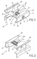
- a device 10 of the inventive arrangement for releasably supporting tubes 40, 41 of a tubular heater, not shown, is shown.
- the device 10 is seen in perspective view from the front and rear. It is constructed from two clamping holders 20, 30.
- the front clamping holder 20 is a cross-sectionally C-shaped metal part, whose base plate forms the front side 21 and whose Side flanges 26, 27 both opposite the mold recesses 24, 24 'have. Starting from the front 21, a through hole 23 is provided centrally in the clamping element 20, in which a clamping screw 11 engages. By means of this clamping screw 11, the front clamping part 20 is connected to the rear clamping part 30.
- the rear clamping part 30 is likewise a metal part. This has to increase the stability of a dome-shaped portion 31, which is bounded to the front by a face plate 39. Centered in the end plate 39, a through hole 33 is introduced for insertion of the clamping screw 11.
- the dome-like section 31 has four walls. Two walls are formed by the top plate 36 and the bottom plate 37 and two further walls are formed by respective side walls. These side walls engage between the top plate 36 and bottom plate 37 and support it.
- the dome-like portion 31 bounded by the four walls forms a receiving space 32 accessible from the rear side, see Fig. 2 , In this receiving space 32, the end of the clamping screw 11 is inserted through the through hole 33.
- This clamping screw 11 is connected at the end to a nut, not shown. This is preferably a square nut, which is held against rotation in the receiving space 32.
- top plate 36 and bottom plate 37 extend in a symmetrical arrangement like a wing.
- the top plate 36 and the bottom plate 37 of the rear clamping element 30 both have mold recesses 34, 34 '.
- the mold recesses 34, 34 'on the top plate 36 and on the bottom plate 37 extend from the free lateral ends of the top plate 36 and bottom plate 37 to the dome-like portion 31, which in this way in case of mounting in contact with the tubes 40, 41st the tubular heater comes. This is better from the FIG. 3 and FIG. 4 to see. It is clear that the clamping elements 20, 30, the tubes 40, 41 in Hold attachment case between them and hold like jaws.
- the clamping connection is achieved by the clamping screw 11, which passes centrally through the clamping elements 20, 30, namely through the through holes 23, 33 and is in communication with the arranged in the receiving space 32 of the clamping element 30 nut.
- the fastening case is achieved when the clamping elements 20, 30 hold the tubes 40, 41 by clamping connection, so that a vertical and axial load does not lead to a detachment of the tubes 40, 41 from the device 10.
- the mounting case is in particular also off Fig. 5 to see.
- the clamping screw 11 is inserted centrally into the clamping element 20 and into the clamping element 30. Starting from the central axis of the clamping screw 11, the clamping elements 20, 30 in the mounting case mirror-symmetrical.
- the dome-like portion 31 engages between the tubes 40, 41 and contacts them at a nip point 35 '(approximately 2 o'clock position relative to tube 40) and at a nip point 35 (approximately 10 o'clock position relative to tube 41).
- the pressure point 35, 35 'in the region of the dome-like portion 31 with the tubes 40, 41 are in the embodiment according to Fig.
- two further contact points 35, 35 ' are provided in the form of recesses 34, 34', namely on the rear side of the tubes 40, 41.
- pinch points 35 ' (approximately at about 11 o'clock position and 1 o'clock position relative to tube 40) and pinch points 35 (approximately at about 11 o'clock position and 1 o'clock position relative to tube 41) is provided.
- the tubes 40, 41 are thus contacted by the clamping element 30 on the top plate 36 and on the lower plate 37 at three pressure points 35 and three pressure points 35 'and opposite of the clamping element 20 at two pressure points 25 and two pressure points 25' of the side flanges 26th , 27.
- This multiple punctiform contact over a wide peripheral region of the tubes 40, 41 with the clamping elements 20, 30 has been found to be particularly advantageous in terms of holding force.
- the clamping elements 20, 30 have the same length in this embodiment.
- the outermost pressure point 25 of the mold recess 24 is opposite to the outer pressure point 35 of the mold recess 34 and the outer pressure point 25 'is opposite to the outer pressure point 35'. This has also been found to be advantageous.
- the device 10 of the inventive arrangement holds both the required axial load, as well as a vertical load by pressure on the tubular heater from above, without the clamping connection for holding the tubes 40, 41 dissolves.
- a bracket 50 to a wall or on a stand.
- a known console 50 shown which consists of two angle parts 51, 52, which are connected via a screw 53 in conjunction.
- the angle part 51 has a slot for a connecting means for attachment to a wall.
- the angle part 52 has a hook 54. Behind these hooks 54 may be provided on the clamping part 30 provided bend 38.
- This bend 38 is best off Fig. 4 to see.
- This bend 38 represents a bend of the lower plate 37 of the clamping element 30.
- Both the upper side 36 and the lower side 37 have an offset, on the one hand for reasons of stability and on the other hand, as described above, for connection to a console 50.
- the invention is not limited to the embodiment shown.
Landscapes
- Engineering & Computer Science (AREA)
- General Engineering & Computer Science (AREA)
- Mechanical Engineering (AREA)
- Physics & Mathematics (AREA)
- Thermal Sciences (AREA)
- Chemical & Material Sciences (AREA)
- Combustion & Propulsion (AREA)
- Clamps And Clips (AREA)
Claims (10)
- Agencement composé d'un dispositif (10) et de tuyaux (40, 41) pour une fixation amovible des tuyaux (40, 41) d'un corps tubulaire de chauffage contre une console (50),
comprenant deux éléments de bridage (20, 30) mis en liaison réciproque par une vis de bridage (11), sachant que la vis de bridage (11) est guidée par des alésages traversants (23, 33) prévus au milieu des éléments de bridage (20, 30),
sachant que l'élément de bridage avant (20) possède au moins deux évidements (24, 24") et que l'élément de bridage arrière (30) possède au moins deux évidements (34, 34') et qu'en cas de fixation pour retenir un corps tubulaire de chauffage les tuyaux (40, 41) peuvent être serrés entre les éléments de bridage (20, 30) dans la zone des évidements (24, 34 ; 24', 34'),
sachant que les évidements (24, 34 ; 24', 34') présentent un contour adapté à la circonférence des tuyaux (40, 41),
caractérisé en ce que
les évidements (24, 24; 34, 34') d'au moins un élément de bridage (20, 30) sont munis de points d'applique (25, 25'; 35, 35') qui dépassent du contour des évidements (24, 34; 24', 34') en direction des tuyaux (40, 41) à retenir. - Agencement selon la revendication 1, caractérisé en ce que sont prévus 2 à 3 points d'applique (25, 25'; 35, 35') par évidement (24, 24; 34, 34').
- Agencement selon la revendication 1 ou 2, caractérisé en ce que l'élément de bridage arrière (30) présente un segment (31) en forme de dôme regardant vers l'avant, qui en cas de fixation pénètre entre les tuyaux (40, 41), sachant que le segment (31) en forme de dôme est limité latéralement par les évidements (34, 34').
- Agencement selon la revendication 3, caractérisé en ce que l'alésage continu (33) destiné à la vis de bridage (11) traverse une plaque frontale avant (39) du segment (31) en forme de dôme.
- Agencement selon la revendication 4, caractérisé en ce que le segment (31) en forme de dôme est formé par la plaque frontale (39) par des segments du côté supérieur (36) ainsi que du côté inférieur (37) de l'élément de bridage arrière (30) et par deux parois latérales, de sorte qu'il en résulte, au dos de l'élément de bridage arrière (30), un compartiment réceptacle (32) ouvert au dos et recevant l'écrou qui interagit avec la vis de bridage (11), de préférence un compartiment réceptacle de section rectangulaire (32) pour un écrou quadrangulaire.
- Agencement selon l'une des revendications 1 à 5, caractérisé en ce que le côté supérieur (36) et le côté inférieur (37) de l'élément de bridage arrière (30) sont coudés verticalement en leur extrémité libre, sachant que de préférence un coude (38) sert à la jonction avec une console (50).
- Agencement avec une console et avec un agencement selon la revendication 6, caractérisé en ce qu'au moyen d'une console (50), il est possible de réaliser une fixation contre un mur ou contre un pied vertical.
- Agencement selon la revendication 1, caractérisé en ce que l'élément de bridage (20) présente une section en forme de C, à savoir une plaque de base (28) avec deux flasques latéraux (26, 27) faisant saillie verticalement, sachant que dans les flasques latéraux (26, 27) ont été moulés les évidements (24, 24').
- Agencement selon la revendication 1, caractérisé en ce qu'un élément ressort (12) est agencé pour faciliter le démontage entre les éléments de bridage (20, 30).
- Agencement selon la revendication 1, caractérisé en ce que les éléments de bridage (20, 30) sont en métal et qu'ils sont fabriqués par emboutissage et cintrage.
Applications Claiming Priority (1)
| Application Number | Priority Date | Filing Date | Title |
|---|---|---|---|
| DE202009011545U DE202009011545U1 (de) | 2009-08-25 | 2009-08-25 | Vorrichtung zur lösbaren Halterung von Röhren eines Röhrenheizkörpers |
Publications (3)
| Publication Number | Publication Date |
|---|---|
| EP2295874A2 EP2295874A2 (fr) | 2011-03-16 |
| EP2295874A3 EP2295874A3 (fr) | 2013-11-27 |
| EP2295874B1 true EP2295874B1 (fr) | 2016-06-08 |
Family
ID=41462079
Family Applications (1)
| Application Number | Title | Priority Date | Filing Date |
|---|---|---|---|
| EP10008410.2A Active EP2295874B1 (fr) | 2009-08-25 | 2010-08-12 | Agencement d'un dispositif et des tuyaux pour une fixation amovible de tuyaux d'un corps tubulaire de chauffage |
Country Status (4)
| Country | Link |
|---|---|
| EP (1) | EP2295874B1 (fr) |
| DE (1) | DE202009011545U1 (fr) |
| HU (1) | HUE029486T2 (fr) |
| PL (1) | PL2295874T3 (fr) |
Families Citing this family (2)
| Publication number | Priority date | Publication date | Assignee | Title |
|---|---|---|---|---|
| CN111236154A (zh) * | 2020-03-05 | 2020-06-05 | 四川鼎恒建设工程有限公司 | 一种水利工程用止水带固定装置及止水带安装方法 |
| CN111237548B (zh) * | 2020-03-17 | 2022-02-11 | 上海三一重机股份有限公司 | 管类固定装置 |
Family Cites Families (7)
| Publication number | Priority date | Publication date | Assignee | Title |
|---|---|---|---|---|
| DE2255166A1 (de) * | 1972-11-10 | 1974-05-16 | Hilti Ag | Heizkoerperhalter |
| FR2247682A1 (en) * | 1973-10-12 | 1975-05-09 | Mueller Franz | Radiator support for adjacent radiator sections - has internal socket in clamping bolt head receiving tool |
| DE29920643U1 (de) | 1999-11-25 | 2000-02-17 | Helmut Pütz GmbH, 51145 Köln | Klemmhalter für die Befestigung eines Röhrenradiators |
| DE20019146U1 (de) * | 2000-11-10 | 2001-01-11 | Zehnder Verkaufs- und Verwaltungs-AG, Gränichen | Haltevorrichtung zur Wandbefestigung eines Röhrenradiators |
| DE202008004548U1 (de) * | 2008-03-28 | 2008-08-14 | Kermi Gmbh | Haltevorrichtung für Röhrenheizkörper |
| DE202008008049U1 (de) * | 2008-06-18 | 2008-09-04 | Kermi Gmbh | Vorrichtung zur klemmenden Halterung und Befestigung von Rohrheizkörpern |
| DE202008008050U1 (de) * | 2008-06-18 | 2008-09-11 | Kermi Gmbh | Vorrichtung zur klemmenden Halterung und Befestigung von Rohrheizkörpern |
-
2009
- 2009-08-25 DE DE202009011545U patent/DE202009011545U1/de not_active Expired - Lifetime
-
2010
- 2010-08-12 EP EP10008410.2A patent/EP2295874B1/fr active Active
- 2010-08-12 HU HUE10008410A patent/HUE029486T2/hu unknown
- 2010-08-12 PL PL10008410.2T patent/PL2295874T3/pl unknown
Also Published As
| Publication number | Publication date |
|---|---|
| DE202009011545U1 (de) | 2009-12-31 |
| EP2295874A3 (fr) | 2013-11-27 |
| EP2295874A2 (fr) | 2011-03-16 |
| PL2295874T3 (pl) | 2016-12-30 |
| HUE029486T2 (hu) | 2017-02-28 |
Similar Documents
| Publication | Publication Date | Title |
|---|---|---|
| EP1987213B1 (fr) | Systeme de coffrage de plafond | |
| EP3303851B1 (fr) | Dispositif pour fixer un composant | |
| EP2091312B2 (fr) | Boîtier électronique pouvant être joint doté de baguettes à crayon ou manchon | |
| DE202017102147U1 (de) | Leitungsdurchführung, insbesondere Zugentlastung für eine Energieführungskette | |
| WO2017036439A1 (fr) | Châssis de maintien pour modules de connecteur à fiche | |
| DE1465318B2 (de) | Elektrischer klemmenblock | |
| DE102005031152A1 (de) | Deckenschalungssystem | |
| EP2295874B1 (fr) | Agencement d'un dispositif et des tuyaux pour une fixation amovible de tuyaux d'un corps tubulaire de chauffage | |
| DE102007011986A1 (de) | Anzeigevorrichtung mit Halteelement | |
| DE19736565C2 (de) | Verbindungsvorrichtung | |
| DE883465C (de) | Befestigungseinrichtung fuer elektrische Geraete u. dgl. | |
| EP0724104A1 (fr) | Elément d'atténuation de contraintes et de fixation | |
| EP3461963B1 (fr) | Système porteur et système d'éléments de connexion permettant la connexion des porteurs | |
| AT390485B (de) | Einrichtung zur kupplung von zwei zueinander in einem winkel befindlichen elementen | |
| DE102008015374B4 (de) | Elektrische Klemme | |
| EP3772778B1 (fr) | Système porteur permettant de fixer un objet oblong ainsi qu'élément rapporté formant agrafe | |
| EP0874423A2 (fr) | Fixation pour barre de courant, barre de courant et assemblage de couplage | |
| EP1785550B1 (fr) | Dispositif de connection | |
| DE102018107886B4 (de) | Steckverbindersystem mit einem bistabilen Element | |
| DE10328406B4 (de) | Schaltschrank insbesondere für Niederspannungsschaltanlagen | |
| DE638445C (de) | Zughebel fuer elektrische Drehschalter | |
| DE10252297A1 (de) | Abstand- und Distanzhalter | |
| EP0730836A1 (fr) | Coulisseau pour tringle à rideau | |
| DE29905254U1 (de) | Gepäckhalterung, insbesondere für Fahrräder | |
| EP2905799A1 (fr) | Système constitué d'un appareil de base et d'un élément auxiliaire |
Legal Events
| Date | Code | Title | Description |
|---|---|---|---|
| PUAI | Public reference made under article 153(3) epc to a published international application that has entered the european phase |
Free format text: ORIGINAL CODE: 0009012 |
|
| AK | Designated contracting states |
Kind code of ref document: A2 Designated state(s): AL AT BE BG CH CY CZ DE DK EE ES FI FR GB GR HR HU IE IS IT LI LT LU LV MC MK MT NL NO PL PT RO SE SI SK SM TR |
|
| AX | Request for extension of the european patent |
Extension state: BA ME RS |
|
| PUAL | Search report despatched |
Free format text: ORIGINAL CODE: 0009013 |
|
| AK | Designated contracting states |
Kind code of ref document: A3 Designated state(s): AL AT BE BG CH CY CZ DE DK EE ES FI FR GB GR HR HU IE IS IT LI LT LU LV MC MK MT NL NO PL PT RO SE SI SK SM TR |
|
| AX | Request for extension of the european patent |
Extension state: BA ME RS |
|
| RIC1 | Information provided on ipc code assigned before grant |
Ipc: F24D 19/02 20060101AFI20131024BHEP Ipc: F16L 3/237 20060101ALI20131024BHEP |
|
| 17P | Request for examination filed |
Effective date: 20140503 |
|
| RBV | Designated contracting states (corrected) |
Designated state(s): AL AT BE BG CH CY CZ DE DK EE ES FI FR GB GR HR HU IE IS IT LI LT LU LV MC MK MT NL NO PL PT RO SE SI SK SM TR |
|
| 17Q | First examination report despatched |
Effective date: 20150625 |
|
| GRAP | Despatch of communication of intention to grant a patent |
Free format text: ORIGINAL CODE: EPIDOSNIGR1 |
|
| INTG | Intention to grant announced |
Effective date: 20160218 |
|
| GRAS | Grant fee paid |
Free format text: ORIGINAL CODE: EPIDOSNIGR3 |
|
| GRAA | (expected) grant |
Free format text: ORIGINAL CODE: 0009210 |
|
| AK | Designated contracting states |
Kind code of ref document: B1 Designated state(s): AL AT BE BG CH CY CZ DE DK EE ES FI FR GB GR HR HU IE IS IT LI LT LU LV MC MK MT NL NO PL PT RO SE SI SK SM TR |
|
| REG | Reference to a national code |
Ref country code: GB Ref legal event code: FG4D Free format text: NOT ENGLISH |
|
| REG | Reference to a national code |
Ref country code: CH Ref legal event code: EP |
|
| REG | Reference to a national code |
Ref country code: IE Ref legal event code: FG4D Free format text: LANGUAGE OF EP DOCUMENT: GERMAN |
|
| REG | Reference to a national code |
Ref country code: AT Ref legal event code: REF Ref document number: 805531 Country of ref document: AT Kind code of ref document: T Effective date: 20160715 |
|
| REG | Reference to a national code |
Ref country code: DE Ref legal event code: R096 Ref document number: 502010011795 Country of ref document: DE |
|
| REG | Reference to a national code |
Ref country code: LT Ref legal event code: MG4D |
|
| REG | Reference to a national code |
Ref country code: NL Ref legal event code: MP Effective date: 20160608 |
|
| PG25 | Lapsed in a contracting state [announced via postgrant information from national office to epo] |
Ref country code: LT Free format text: LAPSE BECAUSE OF FAILURE TO SUBMIT A TRANSLATION OF THE DESCRIPTION OR TO PAY THE FEE WITHIN THE PRESCRIBED TIME-LIMIT Effective date: 20160608 Ref country code: FI Free format text: LAPSE BECAUSE OF FAILURE TO SUBMIT A TRANSLATION OF THE DESCRIPTION OR TO PAY THE FEE WITHIN THE PRESCRIBED TIME-LIMIT Effective date: 20160608 Ref country code: NO Free format text: LAPSE BECAUSE OF FAILURE TO SUBMIT A TRANSLATION OF THE DESCRIPTION OR TO PAY THE FEE WITHIN THE PRESCRIBED TIME-LIMIT Effective date: 20160908 |
|
| PG25 | Lapsed in a contracting state [announced via postgrant information from national office to epo] |
Ref country code: ES Free format text: LAPSE BECAUSE OF FAILURE TO SUBMIT A TRANSLATION OF THE DESCRIPTION OR TO PAY THE FEE WITHIN THE PRESCRIBED TIME-LIMIT Effective date: 20160608 Ref country code: GR Free format text: LAPSE BECAUSE OF FAILURE TO SUBMIT A TRANSLATION OF THE DESCRIPTION OR TO PAY THE FEE WITHIN THE PRESCRIBED TIME-LIMIT Effective date: 20160909 Ref country code: SE Free format text: LAPSE BECAUSE OF FAILURE TO SUBMIT A TRANSLATION OF THE DESCRIPTION OR TO PAY THE FEE WITHIN THE PRESCRIBED TIME-LIMIT Effective date: 20160608 Ref country code: LV Free format text: LAPSE BECAUSE OF FAILURE TO SUBMIT A TRANSLATION OF THE DESCRIPTION OR TO PAY THE FEE WITHIN THE PRESCRIBED TIME-LIMIT Effective date: 20160608 Ref country code: NL Free format text: LAPSE BECAUSE OF FAILURE TO SUBMIT A TRANSLATION OF THE DESCRIPTION OR TO PAY THE FEE WITHIN THE PRESCRIBED TIME-LIMIT Effective date: 20160608 |
|
| PG25 | Lapsed in a contracting state [announced via postgrant information from national office to epo] |
Ref country code: BE Free format text: LAPSE BECAUSE OF NON-PAYMENT OF DUE FEES Effective date: 20160831 |
|
| PG25 | Lapsed in a contracting state [announced via postgrant information from national office to epo] |
Ref country code: RO Free format text: LAPSE BECAUSE OF FAILURE TO SUBMIT A TRANSLATION OF THE DESCRIPTION OR TO PAY THE FEE WITHIN THE PRESCRIBED TIME-LIMIT Effective date: 20160608 Ref country code: EE Free format text: LAPSE BECAUSE OF FAILURE TO SUBMIT A TRANSLATION OF THE DESCRIPTION OR TO PAY THE FEE WITHIN THE PRESCRIBED TIME-LIMIT Effective date: 20160608 Ref country code: IT Free format text: LAPSE BECAUSE OF FAILURE TO SUBMIT A TRANSLATION OF THE DESCRIPTION OR TO PAY THE FEE WITHIN THE PRESCRIBED TIME-LIMIT Effective date: 20160608 Ref country code: SK Free format text: LAPSE BECAUSE OF FAILURE TO SUBMIT A TRANSLATION OF THE DESCRIPTION OR TO PAY THE FEE WITHIN THE PRESCRIBED TIME-LIMIT Effective date: 20160608 Ref country code: IS Free format text: LAPSE BECAUSE OF FAILURE TO SUBMIT A TRANSLATION OF THE DESCRIPTION OR TO PAY THE FEE WITHIN THE PRESCRIBED TIME-LIMIT Effective date: 20161008 |
|
| PG25 | Lapsed in a contracting state [announced via postgrant information from national office to epo] |
Ref country code: SM Free format text: LAPSE BECAUSE OF FAILURE TO SUBMIT A TRANSLATION OF THE DESCRIPTION OR TO PAY THE FEE WITHIN THE PRESCRIBED TIME-LIMIT Effective date: 20160608 Ref country code: PT Free format text: LAPSE BECAUSE OF FAILURE TO SUBMIT A TRANSLATION OF THE DESCRIPTION OR TO PAY THE FEE WITHIN THE PRESCRIBED TIME-LIMIT Effective date: 20161010 |
|
| REG | Reference to a national code |
Ref country code: HU Ref legal event code: AG4A Ref document number: E029486 Country of ref document: HU |
|
| REG | Reference to a national code |
Ref country code: DE Ref legal event code: R097 Ref document number: 502010011795 Country of ref document: DE |
|
| PG25 | Lapsed in a contracting state [announced via postgrant information from national office to epo] |
Ref country code: MC Free format text: LAPSE BECAUSE OF FAILURE TO SUBMIT A TRANSLATION OF THE DESCRIPTION OR TO PAY THE FEE WITHIN THE PRESCRIBED TIME-LIMIT Effective date: 20160608 |
|
| REG | Reference to a national code |
Ref country code: CH Ref legal event code: PL |
|
| PLBE | No opposition filed within time limit |
Free format text: ORIGINAL CODE: 0009261 |
|
| STAA | Information on the status of an ep patent application or granted ep patent |
Free format text: STATUS: NO OPPOSITION FILED WITHIN TIME LIMIT |
|
| PG25 | Lapsed in a contracting state [announced via postgrant information from national office to epo] |
Ref country code: LI Free format text: LAPSE BECAUSE OF NON-PAYMENT OF DUE FEES Effective date: 20160831 Ref country code: CH Free format text: LAPSE BECAUSE OF NON-PAYMENT OF DUE FEES Effective date: 20160831 |
|
| 26N | No opposition filed |
Effective date: 20170309 |
|
| GBPC | Gb: european patent ceased through non-payment of renewal fee |
Effective date: 20160908 |
|
| REG | Reference to a national code |
Ref country code: FR Ref legal event code: ST Effective date: 20170428 |
|
| PG25 | Lapsed in a contracting state [announced via postgrant information from national office to epo] |
Ref country code: SI Free format text: LAPSE BECAUSE OF FAILURE TO SUBMIT A TRANSLATION OF THE DESCRIPTION OR TO PAY THE FEE WITHIN THE PRESCRIBED TIME-LIMIT Effective date: 20160608 Ref country code: DK Free format text: LAPSE BECAUSE OF FAILURE TO SUBMIT A TRANSLATION OF THE DESCRIPTION OR TO PAY THE FEE WITHIN THE PRESCRIBED TIME-LIMIT Effective date: 20160608 |
|
| REG | Reference to a national code |
Ref country code: IE Ref legal event code: MM4A |
|
| PG25 | Lapsed in a contracting state [announced via postgrant information from national office to epo] |
Ref country code: FR Free format text: LAPSE BECAUSE OF NON-PAYMENT OF DUE FEES Effective date: 20160831 Ref country code: GB Free format text: LAPSE BECAUSE OF NON-PAYMENT OF DUE FEES Effective date: 20160908 Ref country code: IE Free format text: LAPSE BECAUSE OF NON-PAYMENT OF DUE FEES Effective date: 20160812 |
|
| PG25 | Lapsed in a contracting state [announced via postgrant information from national office to epo] |
Ref country code: LU Free format text: LAPSE BECAUSE OF NON-PAYMENT OF DUE FEES Effective date: 20160812 |
|
| PG25 | Lapsed in a contracting state [announced via postgrant information from national office to epo] |
Ref country code: CY Free format text: LAPSE BECAUSE OF FAILURE TO SUBMIT A TRANSLATION OF THE DESCRIPTION OR TO PAY THE FEE WITHIN THE PRESCRIBED TIME-LIMIT Effective date: 20160608 |
|
| PG25 | Lapsed in a contracting state [announced via postgrant information from national office to epo] |
Ref country code: MT Free format text: LAPSE BECAUSE OF FAILURE TO SUBMIT A TRANSLATION OF THE DESCRIPTION OR TO PAY THE FEE WITHIN THE PRESCRIBED TIME-LIMIT Effective date: 20160608 Ref country code: TR Free format text: LAPSE BECAUSE OF FAILURE TO SUBMIT A TRANSLATION OF THE DESCRIPTION OR TO PAY THE FEE WITHIN THE PRESCRIBED TIME-LIMIT Effective date: 20160608 Ref country code: HR Free format text: LAPSE BECAUSE OF FAILURE TO SUBMIT A TRANSLATION OF THE DESCRIPTION OR TO PAY THE FEE WITHIN THE PRESCRIBED TIME-LIMIT Effective date: 20160608 Ref country code: MK Free format text: LAPSE BECAUSE OF FAILURE TO SUBMIT A TRANSLATION OF THE DESCRIPTION OR TO PAY THE FEE WITHIN THE PRESCRIBED TIME-LIMIT Effective date: 20160608 |
|
| PG25 | Lapsed in a contracting state [announced via postgrant information from national office to epo] |
Ref country code: BG Free format text: LAPSE BECAUSE OF FAILURE TO SUBMIT A TRANSLATION OF THE DESCRIPTION OR TO PAY THE FEE WITHIN THE PRESCRIBED TIME-LIMIT Effective date: 20160608 |
|
| PG25 | Lapsed in a contracting state [announced via postgrant information from national office to epo] |
Ref country code: AL Free format text: LAPSE BECAUSE OF FAILURE TO SUBMIT A TRANSLATION OF THE DESCRIPTION OR TO PAY THE FEE WITHIN THE PRESCRIBED TIME-LIMIT Effective date: 20160608 |
|
| PGFP | Annual fee paid to national office [announced via postgrant information from national office to epo] |
Ref country code: PL Payment date: 20220629 Year of fee payment: 13 |
|
| P01 | Opt-out of the competence of the unified patent court (upc) registered |
Effective date: 20230628 |
|
| PGFP | Annual fee paid to national office [announced via postgrant information from national office to epo] |
Ref country code: CZ Payment date: 20230724 Year of fee payment: 14 Ref country code: AT Payment date: 20230824 Year of fee payment: 14 |
|
| PGFP | Annual fee paid to national office [announced via postgrant information from national office to epo] |
Ref country code: HU Payment date: 20230803 Year of fee payment: 14 |
|
| PG25 | Lapsed in a contracting state [announced via postgrant information from national office to epo] |
Ref country code: PL Free format text: LAPSE BECAUSE OF NON-PAYMENT OF DUE FEES Effective date: 20230812 |
|
| PG25 | Lapsed in a contracting state [announced via postgrant information from national office to epo] |
Ref country code: PL Free format text: LAPSE BECAUSE OF NON-PAYMENT OF DUE FEES Effective date: 20230812 |
|
| REG | Reference to a national code |
Ref country code: AT Ref legal event code: MM01 Ref document number: 805531 Country of ref document: AT Kind code of ref document: T Effective date: 20240812 |
|
| PG25 | Lapsed in a contracting state [announced via postgrant information from national office to epo] |
Ref country code: HU Free format text: LAPSE BECAUSE OF NON-PAYMENT OF DUE FEES Effective date: 20240813 |
|
| PG25 | Lapsed in a contracting state [announced via postgrant information from national office to epo] |
Ref country code: AT Free format text: LAPSE BECAUSE OF NON-PAYMENT OF DUE FEES Effective date: 20240812 |
|
| PG25 | Lapsed in a contracting state [announced via postgrant information from national office to epo] |
Ref country code: CZ Free format text: LAPSE BECAUSE OF NON-PAYMENT OF DUE FEES Effective date: 20240812 |
|
| PGFP | Annual fee paid to national office [announced via postgrant information from national office to epo] |
Ref country code: DE Payment date: 20250725 Year of fee payment: 16 |