EP2295897A1 - Appareil frigorifique et dispositif de liquéfaction correspondant - Google Patents
Appareil frigorifique et dispositif de liquéfaction correspondant Download PDFInfo
- Publication number
- EP2295897A1 EP2295897A1 EP10170364A EP10170364A EP2295897A1 EP 2295897 A1 EP2295897 A1 EP 2295897A1 EP 10170364 A EP10170364 A EP 10170364A EP 10170364 A EP10170364 A EP 10170364A EP 2295897 A1 EP2295897 A1 EP 2295897A1
- Authority
- EP
- European Patent Office
- Prior art keywords
- condenser
- refrigerating appliance
- housing wall
- coolant line
- appliance according
- Prior art date
- Legal status (The legal status is an assumption and is not a legal conclusion. Google has not performed a legal analysis and makes no representation as to the accuracy of the status listed.)
- Withdrawn
Links
- 239000002826 coolant Substances 0.000 claims abstract description 41
- 125000006850 spacer group Chemical group 0.000 claims description 19
- 238000005057 refrigeration Methods 0.000 claims description 14
- 239000000853 adhesive Substances 0.000 claims description 6
- 230000001070 adhesive effect Effects 0.000 claims description 6
- 239000004831 Hot glue Substances 0.000 claims 1
- 241000446313 Lamella Species 0.000 abstract description 3
- 238000005452 bending Methods 0.000 description 5
- 238000009434 installation Methods 0.000 description 4
- 238000004026 adhesive bonding Methods 0.000 description 3
- 238000003475 lamination Methods 0.000 description 3
- 230000015572 biosynthetic process Effects 0.000 description 2
- 238000004519 manufacturing process Methods 0.000 description 2
- 238000000034 method Methods 0.000 description 2
- 239000003507 refrigerant Substances 0.000 description 2
- 230000006735 deficit Effects 0.000 description 1
- 238000010438 heat treatment Methods 0.000 description 1
- 238000007373 indentation Methods 0.000 description 1
- 239000000463 material Substances 0.000 description 1
- 239000002184 metal Substances 0.000 description 1
- 230000010355 oscillation Effects 0.000 description 1
- 238000005192 partition Methods 0.000 description 1
- 238000000926 separation method Methods 0.000 description 1
- 230000007704 transition Effects 0.000 description 1
- 238000005303 weighing Methods 0.000 description 1
Images


Classifications
-
- F—MECHANICAL ENGINEERING; LIGHTING; HEATING; WEAPONS; BLASTING
- F25—REFRIGERATION OR COOLING; COMBINED HEATING AND REFRIGERATION SYSTEMS; HEAT PUMP SYSTEMS; MANUFACTURE OR STORAGE OF ICE; LIQUEFACTION SOLIDIFICATION OF GASES
- F25B—REFRIGERATION MACHINES, PLANTS OR SYSTEMS; COMBINED HEATING AND REFRIGERATION SYSTEMS; HEAT PUMP SYSTEMS
- F25B39/00—Evaporators; Condensers
- F25B39/04—Condensers
-
- F—MECHANICAL ENGINEERING; LIGHTING; HEATING; WEAPONS; BLASTING
- F25—REFRIGERATION OR COOLING; COMBINED HEATING AND REFRIGERATION SYSTEMS; HEAT PUMP SYSTEMS; MANUFACTURE OR STORAGE OF ICE; LIQUEFACTION SOLIDIFICATION OF GASES
- F25D—REFRIGERATORS; COLD ROOMS; ICE-BOXES; COOLING OR FREEZING APPARATUS NOT OTHERWISE PROVIDED FOR
- F25D23/00—General constructional features
- F25D23/006—General constructional features for mounting refrigerating machinery components
-
- F—MECHANICAL ENGINEERING; LIGHTING; HEATING; WEAPONS; BLASTING
- F28—HEAT EXCHANGE IN GENERAL
- F28D—HEAT-EXCHANGE APPARATUS, NOT PROVIDED FOR IN ANOTHER SUBCLASS, IN WHICH THE HEAT-EXCHANGE MEDIA DO NOT COME INTO DIRECT CONTACT
- F28D1/00—Heat-exchange apparatus having stationary conduit assemblies for one heat-exchange medium only, the media being in contact with different sides of the conduit wall, in which the other heat-exchange medium is a large body of fluid, e.g. domestic or motor car radiators
- F28D1/02—Heat-exchange apparatus having stationary conduit assemblies for one heat-exchange medium only, the media being in contact with different sides of the conduit wall, in which the other heat-exchange medium is a large body of fluid, e.g. domestic or motor car radiators with heat-exchange conduits immersed in the body of fluid
- F28D1/04—Heat-exchange apparatus having stationary conduit assemblies for one heat-exchange medium only, the media being in contact with different sides of the conduit wall, in which the other heat-exchange medium is a large body of fluid, e.g. domestic or motor car radiators with heat-exchange conduits immersed in the body of fluid with tubular conduits
- F28D1/047—Heat-exchange apparatus having stationary conduit assemblies for one heat-exchange medium only, the media being in contact with different sides of the conduit wall, in which the other heat-exchange medium is a large body of fluid, e.g. domestic or motor car radiators with heat-exchange conduits immersed in the body of fluid with tubular conduits the conduits being bent, e.g. in a serpentine or zig-zag
- F28D1/0477—Heat-exchange apparatus having stationary conduit assemblies for one heat-exchange medium only, the media being in contact with different sides of the conduit wall, in which the other heat-exchange medium is a large body of fluid, e.g. domestic or motor car radiators with heat-exchange conduits immersed in the body of fluid with tubular conduits the conduits being bent, e.g. in a serpentine or zig-zag the conduits being bent in a serpentine or zig-zag
-
- F—MECHANICAL ENGINEERING; LIGHTING; HEATING; WEAPONS; BLASTING
- F28—HEAT EXCHANGE IN GENERAL
- F28F—DETAILS OF HEAT-EXCHANGE AND HEAT-TRANSFER APPARATUS, OF GENERAL APPLICATION
- F28F1/00—Tubular elements; Assemblies of tubular elements
- F28F1/10—Tubular elements and assemblies thereof with means for increasing heat-transfer area, e.g. with fins, with projections, with recesses
- F28F1/12—Tubular elements and assemblies thereof with means for increasing heat-transfer area, e.g. with fins, with projections, with recesses the means being only outside the tubular element
- F28F1/122—Tubular elements and assemblies thereof with means for increasing heat-transfer area, e.g. with fins, with projections, with recesses the means being only outside the tubular element and being formed of wires
-
- F—MECHANICAL ENGINEERING; LIGHTING; HEATING; WEAPONS; BLASTING
- F25—REFRIGERATION OR COOLING; COMBINED HEATING AND REFRIGERATION SYSTEMS; HEAT PUMP SYSTEMS; MANUFACTURE OR STORAGE OF ICE; LIQUEFACTION SOLIDIFICATION OF GASES
- F25B—REFRIGERATION MACHINES, PLANTS OR SYSTEMS; COMBINED HEATING AND REFRIGERATION SYSTEMS; HEAT PUMP SYSTEMS
- F25B2500/00—Problems to be solved
- F25B2500/01—Geometry problems, e.g. for reducing size
-
- F—MECHANICAL ENGINEERING; LIGHTING; HEATING; WEAPONS; BLASTING
- F28—HEAT EXCHANGE IN GENERAL
- F28F—DETAILS OF HEAT-EXCHANGE AND HEAT-TRANSFER APPARATUS, OF GENERAL APPLICATION
- F28F2240/00—Spacing means
-
- F—MECHANICAL ENGINEERING; LIGHTING; HEATING; WEAPONS; BLASTING
- F28—HEAT EXCHANGE IN GENERAL
- F28F—DETAILS OF HEAT-EXCHANGE AND HEAT-TRANSFER APPARATUS, OF GENERAL APPLICATION
- F28F2275/00—Fastening; Joining
- F28F2275/02—Fastening; Joining by using bonding materials; by embedding elements in particular materials
- F28F2275/025—Fastening; Joining by using bonding materials; by embedding elements in particular materials by using adhesives
Definitions
- the invention relates to a refrigeration appliance, in particular a domestic refrigeration appliance, with a housing and with a condenser, which is arranged on a housing wall, wherein the condenser comprises a meander-shaped coolant line which extends in a condenser.
- DE 202006002418 U1 describes a refrigerator or freezer with a condenser, which in one embodiment has a cardboard rear wall for acoustic decoupling of its device housing relative to the condenser. On the cardboard rear wall, a fastening means is glued, which in turn serves as a fastening means for a condenser.
- the object of the invention is to simplify the assembly of a condenser to a refrigeration device.
- a refrigeration appliance is understood in particular to mean a household refrigerating appliance, that is to say a refrigeration appliance that is used for household management, such as, for example, a refrigerator, a freezer or a fridge-freezer combination.
- An essential part of a refrigeration device is a refrigeration cycle, which consists of a refrigerant line, a compressor, an evaporator, a condenser and a throttle and in which a coolant circulates.
- a condenser generally includes a portion of the coolant line in which the coolant line meanders. The condenser is preferably arranged outside the housing of the refrigeration device, since the refrigerant is liquefied in it with the release of thermal energy.
- the condenser In a refrigerator, in particular household refrigeration appliance, with a housing and with a condenser, which is arranged on a housing wall, wherein the condenser comprises a meander-shaped coolant line which extends in a condenser, according to the invention, the condenser has subsections which protrude from the condenser and on the one hand spacers of the condenser opposite the housing wall and on the other hand form contact surfaces for attachment of the condenser to the housing wall.
- the housing wall is in particular the rear wall of the housing, on the outside of which the condenser is attached.
- the sections can already be formed during the production of the condenser or only later on a conventional condenser.
- the condenser according to the invention can therefore be advantageously prepared by means of suitable forming process from a commercial condenser.
- the deformation can z. B. by bending partial surfaces of the condenser, optionally with heating.
- a condenser may also be shaped such that it no longer forms a continuous condenser plane, but z. B. has a V or arcuate cross-section. Then the condenser has contact surfaces and a distance from the outside of the device, but not a constant distance to a regularly planar device wall. This has in the installation of the refrigerator in a household, especially in front of a room wall in a kitchen or a cellar, an increased space between the housing outer wall and the environment result.
- a condenser Regularly, a condenser includes the meandering laid coolant line and a plurality of parallel slats attached thereto, which span the meanders and form a lamellar layer. Under lamellae, in particular metallic wires can be understood, which are preferably thermally conductively connected to the coolant line, for example, are welded.
- the meander-shaped coolant line and the fins have the task of increasing the heat-emitting surface of the condenser to efficiently cool the coolant.
- condensers without, with one or more lamellar layers, which usually extend over the entire coolant line and form with it the condenser.
- the condenser is covered on one side or on both sides of the coolant line by a lamellar layer which extends in the condenser plane substantially over the entire coolant line.
- the partial surfaces according to the invention can also be formed on a condenser with lamellar layer.
- the above-described condenser shaped according to the invention can be fixedly attached to a housing wall, in particular a housing outside, of a refrigeration appliance by means of suitable fastening means.
- fastening means for example, screw, riveting or Klips systems are possible.
- a fastening means the gluing, in particular the gluing means of so-called hotmelting systems provided.
- Gluing has the mounting advantage that the adhesive surfaces, ie the contact surfaces on the condenser and the corresponding contact surfaces on the housing wall, in the contact plane need not be positioned as accurately as z. B. holes for Schaubsysteme. In this way, omnipresent tolerances of Verhessigers or the housing wall can be compensated and yet a precise installation of the condenser can be ensured to the housing wall.
- Another advantage of using adhesives is the ability to choose larger contact surfaces without significant additional effort. As a result, lower performance and thus cheaper adhesive can be used.
- the adhesive connection is often at least slightly elastic and transmits vibrations between the refrigerator and the condenser less than z. B. screw, so that a glued condenser is quieter in operation.
- the contact surfaces have a distance to the condenser of about 10 - 100 mm, in particular 20 mm.
- the refrigerator has minimal external dimensions, so that it can be installed in a space-saving manner.
- the maximum distance of about 100 mm allows the heat dissipating condenser to be placed as far away as possible from the thermally insulated housing wall.
- a distance of 20mm represents a compromise, weighing the conflicting interests between the largest possible and the shortest possible distance.
- the sections may be attached at any location in the condenser plane.
- the sections are formed on an edge and / or in a central region of the condenser. Partitions in the edge area are easier to access than central areas, which is why they facilitate the installation of the condenser.
- a central region of the condenser for the arrangement of a section which contacts the housing wall, excessive oscillation of particularly large condensers can be prevented.
- the protruding sections of the condenser according to the invention can be arranged over the entire length or width of the condenser, so that the condenser is bent as a whole, in any case so the coolant line and, if present, also the lamellar layer.
- This has the advantage on the one hand that a simple bending process over the entire length or width also requires only simply designed bending devices. In addition, this creates large-scale sections that allow a less tolerance-sensitive installation and possibly simpler adhesive systems.
- the sections may be formed exclusively on a lamellar layer.
- the coolant line does not have to be bent. This has the advantage, in particular in the case of a subsequent embodiment of the sections, that unwanted cross-sectional impairments of the coolant line, damage or even leaks are avoided, which can occur when the coolant line is bent. A bending that is carried out only in the lamellar layer, does not affect the operation of the condenser.
- a plurality of adjacent lamellae which run continuously over all meanders of the coolant line, can be bent out of the condenser plane in a quasi-hump-shaped manner with a plateau-shaped flattening. By their hump form they form spacers whose plateau-shaped flattening represent contact surfaces. Due to their uninterrupted course, the bent blades do not destabilize the condenser. In a subsequent embodiment of this embodiment, however, the distance of the straight sections of a meander of the coolant line, within which the fins are bent, reduce the meander so close. Because the bent-out slats can not be extended subsequently, as a rule, which shortens the distance they originally bridged originally.
- a plurality of adjacent lamellae of one or more lamination layers are severed and e.g. Z-shaped so bent out of the condenser plane in a direction that they form the spacer and the contact surface.
- This variant requires the least changes in the spatial shape of the condenser, so it is predestined for subsequent production of the sections. It is easy to make without altering the original shape of the condenser.
- the protruding sections may be formed together on one layer alone or also on a plurality of lamellae layers.
- the training on only one lamellar layer speaks the lower cost.
- a denser contact surface of lamellae of both layers can be formed.
- the spacer thus formed can also be more stable as a rule, because it can form spacers with different inclinations.
- the object is also achieved by a condenser alone with the features of claim 10. It can already be manufactured at the factory in the manner described above or can only be created later by reshaping a commercially available liquefier.
- FIG. 1 shows a perspective view of a refrigeration device using the example of a refrigerator with a housing 1.
- the cubic housing 1 has a housing wall 2, which may be a rear wall of the housing 1 in particular.
- the housing wall 2 is substantially flat, even if it may have smaller or larger indentations, for example, receive a compressor. If the housing wall 2 is the rear wall of the housing 1, it is located on the opposite side with respect to a door side 14 of the refrigerator.
- a substantially planar condenser 3 is attached at a distance 13 to her.
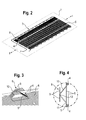
- FIG. 2 shows a first embodiment of a condenser 3 according to the invention in a perspective view. It consists of a meander-shaped coolant line 4, to which mutually parallel laminar layers 6 are attached.
- the lamellar layers 6 consist of a plurality of parallel juxtaposed rectilinear lamellae 5, which are fastened to the coolant line 4 at each contact point.
- the coolant line 4 and the laminar layers 6 are largely in one plane, the condenser 7, and form a plate-shaped unit.
- FIG. 3 illustrates the formation of inventive subsections 8: From the upper lamellar layer 6 a plurality of adjacent lamellae 5 are substantially perpendicular to the Lamell michsraum and severed directly on a meander of the coolant line 4. The lower lamellar layer remains untouched. The individual severed lamellae 5 are bent twice and in such a way that they protrude from the condenser plane 7. They form the subsection 8 of the condenser 3, which also represents a spacer 10 of the condenser 3 relative to the housing wall 2 and a flat contact surface 9 for its attachment to the housing wall 2. The spacers 10 rise in a ramp shape from the condenser 7 and go into the contact surfaces 9, which are parallel to the condenser 7. Since the lamellae 5 usually consist of a profiled metal in cross section, the sections 8 with their spacers 10 and the contact surfaces 9 have a sufficient dimensional stability.
- FIG. 4 is a section along the line I - I out FIG. 2 shown enlarged by the section 8.
- the coolant lines 4 are cut at right angles and have a circular cross-section.
- the section 8 is formed only from the left in the sectional view slat layer 6.
- the blades 5 are severed immediately behind a meander of the coolant line 4 and from the condenser 7 (see. FIG. 2 ) bent out. After a first bend 11, they initially rise as spacers 10, in order to transition into the contact surface 9 after a second bend 12, which runs parallel to the lamellar layer 6. The steeper the spacer 10 is bent, the greater the distance formed by it can be.
- the bent blades can also be alternately from one and the opposite be bent on the other side to comb in a contact surface with each other. As a result, a possibly smaller, but denser contact surface can be formed.
- FIG. 5 shows a further embodiment of the condenser 3 according to the invention in one of FIG. 3 corresponding view.
- it consists of a meander-shaped coolant line 4, to which laminar layers 6, which are parallel on both sides, are attached.
- a plurality of adjacent lamellae 5 are severed directly at the coolant line 4 substantially perpendicular to the lamination direction both from the upper and from the lower lamella layer 6.
- the lower and upper fins 5 are also double and bent out so that they protrude from the condenser 7. They result in a side view the shape of a quasi-flat drawn "Z".
- the upper and lower blades 5 together form a spacer 10 which, as in FIG FIG. 3 ramps up from the condenser 7 and merges into the contact surfaces 9, which are parallel to the condenser 7.
- FIG. 6 shows a section along the line I - I out FIG. 2 through the section 8 from FIG. 5 ,
- the coolant line 4 is cut at right angles and therefore has a circular cross section.
- the section 8 is formed both from the left and right in the sectional view lamellar layer 6.
- the first bend 11 and the second bend 12 of the upper and lower lamellae 5 each lie directly on a coolant line 4 and one above the other.
- the upper fins 5 are slightly longer after bending and protrude at a shallower angle out of the condenser 7 than the lower fins 5. The steeper the spacer 10 is bent, the greater is the distance generated by him.
- FIG. 7 Another embodiment of the condenser 3 according to the invention is shown in FIG. 7 shown.
- the condenser 3 in turn consists of a meander-shaped coolant line 4, to which a lamination layer 6 is attached.
- the sections 8 are formed exclusively on the lamellar layer 6 and over the entire width of the condenser, without affecting the course of the coolant line 4 in itself substantially. They are arranged between the meanders of the coolant line 4.
- the sections 8 of the lamellar layer 6 protrude quasi arched or bridge-shaped out of the condenser 7 and form each lamella 5 two projecting spacers 10th and one to the liquefier 7 (see. FIG. 2 ) parallel portion of a contact surface 9 for attachment.
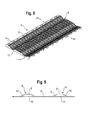
- FIG. 7 shows which sections according to FIG. 7 formed in a transverse direction to the longitudinal extent of the condenser 3, so shows FIG. 8 an embodiment with longitudinally extended sections 8.
- the entire condenser 3 is deformed, ie both the coolant lines 4 and the lamellar layers 6.
- individual slats 5 are not necessarily affected by a deformation, because they can pass undisturbed and linear over the entire length of the condenser 3.
- the coolant line 4 is concerned, which is now partially curved or bridge-shaped.
- This embodiment is also suitable for a subsequent embodiment of the sections 8.
- FIG. 9 shows a section along the line II - II FIG. 8 through the condenser 3.
- the contact surfaces 9 consist of the sections 8 of the deformed coolant line 4 and the lamellar layers 6. Only one feed section 15 (see. FIG. 8 ) of the coolant line 4 runs undeformed and completely in the condenser 7 (see. FIG. 2 ).
- the foregoing condensers described in detail are embodiments, they may be modified in a conventional manner to a wide extent by those skilled in the art without departing from the scope of the invention.
- the upper lamellae 5 can protrude out of the condenser plane 7 at the same angle or at a different angle as shown, like the lower ones.
- other separation points and staggered bends 11 and 12 can be selected.
- the concrete embodiments of the condenser may follow in a different form than in the rectangular described here, if this is necessary for reasons of space or designerischen reasons.
- the use of the indefinite article "on" or "one” does not exclude that the characteristics in question may also be present multiple times.
Landscapes
- Engineering & Computer Science (AREA)
- Physics & Mathematics (AREA)
- Mechanical Engineering (AREA)
- Thermal Sciences (AREA)
- General Engineering & Computer Science (AREA)
- Chemical & Material Sciences (AREA)
- Combustion & Propulsion (AREA)
- Geometry (AREA)
- Devices That Are Associated With Refrigeration Equipment (AREA)
- Refrigerator Housings (AREA)
Applications Claiming Priority (1)
| Application Number | Priority Date | Filing Date | Title |
|---|---|---|---|
| DE102009028179A DE102009028179A1 (de) | 2009-08-03 | 2009-08-03 | Kältegerät und Verflüssiger dafür |
Publications (1)
| Publication Number | Publication Date |
|---|---|
| EP2295897A1 true EP2295897A1 (fr) | 2011-03-16 |
Family
ID=43216720
Family Applications (1)
| Application Number | Title | Priority Date | Filing Date |
|---|---|---|---|
| EP10170364A Withdrawn EP2295897A1 (fr) | 2009-08-03 | 2010-07-22 | Appareil frigorifique et dispositif de liquéfaction correspondant |
Country Status (2)
| Country | Link |
|---|---|
| EP (1) | EP2295897A1 (fr) |
| DE (1) | DE102009028179A1 (fr) |
Cited By (1)
| Publication number | Priority date | Publication date | Assignee | Title |
|---|---|---|---|---|
| CN108278827A (zh) * | 2018-01-23 | 2018-07-13 | 合肥美的电冰箱有限公司 | 冰箱、冷凝器控制方法及计算机可读存储介质 |
Families Citing this family (2)
| Publication number | Priority date | Publication date | Assignee | Title |
|---|---|---|---|---|
| DE102016015300A1 (de) | 2016-12-22 | 2018-06-28 | Daimler Ag | Kühlmittelleitung für ein Fahrzeug, insbesondere für ein Kraftfahrzeug |
| WO2019020175A1 (fr) * | 2017-07-26 | 2019-01-31 | Electrolux Appliances Aktiebolag | Appareil de refroidissement comprenant un condenseur |
Citations (4)
| Publication number | Priority date | Publication date | Assignee | Title |
|---|---|---|---|---|
| JPS49151175U (fr) * | 1973-04-28 | 1974-12-27 | ||
| JPS55168184U (fr) * | 1979-05-21 | 1980-12-03 | ||
| JPH10148451A (ja) * | 1996-11-20 | 1998-06-02 | Matsushita Refrig Co Ltd | 冷蔵庫 |
| DE202006002418U1 (de) | 2005-11-11 | 2007-03-29 | Liebherr-Hausgeräte Lienz Gmbh | Kühl- und/oder Gefriergerät |
Family Cites Families (1)
| Publication number | Priority date | Publication date | Assignee | Title |
|---|---|---|---|---|
| GB2142857A (en) * | 1983-06-15 | 1985-01-30 | Fulton | Manufacture of heat exchangers by welding |
-
2009
- 2009-08-03 DE DE102009028179A patent/DE102009028179A1/de not_active Ceased
-
2010
- 2010-07-22 EP EP10170364A patent/EP2295897A1/fr not_active Withdrawn
Patent Citations (4)
| Publication number | Priority date | Publication date | Assignee | Title |
|---|---|---|---|---|
| JPS49151175U (fr) * | 1973-04-28 | 1974-12-27 | ||
| JPS55168184U (fr) * | 1979-05-21 | 1980-12-03 | ||
| JPH10148451A (ja) * | 1996-11-20 | 1998-06-02 | Matsushita Refrig Co Ltd | 冷蔵庫 |
| DE202006002418U1 (de) | 2005-11-11 | 2007-03-29 | Liebherr-Hausgeräte Lienz Gmbh | Kühl- und/oder Gefriergerät |
Cited By (2)
| Publication number | Priority date | Publication date | Assignee | Title |
|---|---|---|---|---|
| CN108278827A (zh) * | 2018-01-23 | 2018-07-13 | 合肥美的电冰箱有限公司 | 冰箱、冷凝器控制方法及计算机可读存储介质 |
| CN108278827B (zh) * | 2018-01-23 | 2020-09-04 | 合肥美的电冰箱有限公司 | 冰箱、冷凝器控制方法及计算机可读存储介质 |
Also Published As
| Publication number | Publication date |
|---|---|
| DE102009028179A1 (de) | 2011-02-17 |
Similar Documents
| Publication | Publication Date | Title |
|---|---|---|
| EP0374896A2 (fr) | Condenseur à tube aplati, procédé de fabrication et applications | |
| EP3499145B1 (fr) | Arrangement d'un dispositif de mise en température d'un espace sous un plafond | |
| DE202010006739U1 (de) | Durchlauferhitzer | |
| EP0196672A2 (fr) | Panneaux pour recouvrir les murs extérieurs de bâtiments | |
| DE102007047006A1 (de) | Kältegerät mit einem Halter für einen Abschnitt einer Kältemittelrohrleitung | |
| DE19540770C2 (de) | Kühldeckenelement | |
| DE202009000717U1 (de) | Decken- oder Wandwärmetauscherelement | |
| EP2694890B1 (fr) | Appareil de froid ménager pourvu de plaques d'évaporation reliées par des éléments jointifs | |
| EP2295897A1 (fr) | Appareil frigorifique et dispositif de liquéfaction correspondant | |
| EP2295871B1 (fr) | Unité plafonnière de chauffage et/ou de refroidissement | |
| DE102012106157A1 (de) | Lamellenelement und Verfahren zur Herstellung des Lamellenelements | |
| DE202017102436U1 (de) | Wärmetauscher mit Mikrokanal-Struktur oder Flügelrohr-Struktur | |
| EP2762787A2 (fr) | Élément climatique pour un plafond chauffant et refroidissant | |
| WO2008077699A1 (fr) | Groupe échangeur thermique | |
| AT504806B1 (de) | Zarge für feuerschutztüren, welche aus mehreren parallel verlaufenden teilprofilen gebildet wird | |
| EP0918199B1 (fr) | Réfrigérateur | |
| EP4375604A1 (fr) | Échangeur de chaleur à ailettes, son procédé de fabrication et système | |
| EP3025617B1 (fr) | Barre de liaison avec entretoise | |
| WO2007000444A2 (fr) | Dispositif de chauffage et/ou de refroidissement d'une piece | |
| EP4095451B1 (fr) | Procédé de fabrication d'un dispositif de mise en température d'un espace | |
| EP2556319B1 (fr) | Échangeur de chaleur tubulaire métallique, son procédé de fabrication et appareil de réfrigération utilisant celui-ci | |
| WO2007042331A1 (fr) | Plaque d'echangeur thermique | |
| EP1712857A2 (fr) | Réfrigérateur et/ou congélateur | |
| CH707507B1 (de) | Klimaelement für eine Heiz- und Kühldecke. | |
| EP1184638A2 (fr) | Profilé conducteur de chaleur |
Legal Events
| Date | Code | Title | Description |
|---|---|---|---|
| PUAI | Public reference made under article 153(3) epc to a published international application that has entered the european phase |
Free format text: ORIGINAL CODE: 0009012 |
|
| AK | Designated contracting states |
Kind code of ref document: A1 Designated state(s): AL AT BE BG CH CY CZ DE DK EE ES FI FR GB GR HR HU IE IS IT LI LT LU LV MC MK MT NL NO PL PT RO SE SI SK SM TR |
|
| AX | Request for extension of the european patent |
Extension state: BA ME RS |
|
| 17P | Request for examination filed |
Effective date: 20110916 |
|
| RAP1 | Party data changed (applicant data changed or rights of an application transferred) |
Owner name: BSH HAUSGERAETE GMBH |
|
| 17Q | First examination report despatched |
Effective date: 20170704 |
|
| GRAP | Despatch of communication of intention to grant a patent |
Free format text: ORIGINAL CODE: EPIDOSNIGR1 |
|
| RIC1 | Information provided on ipc code assigned before grant |
Ipc: F28D 1/047 20060101ALI20180626BHEP Ipc: F25B 39/04 20060101ALI20180626BHEP Ipc: F28F 1/12 20060101AFI20180626BHEP Ipc: F25D 23/00 20060101ALI20180626BHEP |
|
| INTG | Intention to grant announced |
Effective date: 20180730 |
|
| STAA | Information on the status of an ep patent application or granted ep patent |
Free format text: STATUS: THE APPLICATION IS DEEMED TO BE WITHDRAWN |
|
| 18D | Application deemed to be withdrawn |
Effective date: 20181211 |