EP4375604A1 - Échangeur de chaleur à ailettes, son procédé de fabrication et système - Google Patents
Échangeur de chaleur à ailettes, son procédé de fabrication et système Download PDFInfo
- Publication number
- EP4375604A1 EP4375604A1 EP23211761.4A EP23211761A EP4375604A1 EP 4375604 A1 EP4375604 A1 EP 4375604A1 EP 23211761 A EP23211761 A EP 23211761A EP 4375604 A1 EP4375604 A1 EP 4375604A1
- Authority
- EP
- European Patent Office
- Prior art keywords
- heat exchanger
- fins
- pipe
- fin
- pipe system
- Prior art date
- Legal status (The legal status is an assumption and is not a legal conclusion. Google has not performed a legal analysis and makes no representation as to the accuracy of the status listed.)
- Granted
Links
Images




Classifications
-
- F—MECHANICAL ENGINEERING; LIGHTING; HEATING; WEAPONS; BLASTING
- F28—HEAT EXCHANGE IN GENERAL
- F28D—HEAT-EXCHANGE APPARATUS, NOT PROVIDED FOR IN ANOTHER SUBCLASS, IN WHICH THE HEAT-EXCHANGE MEDIA DO NOT COME INTO DIRECT CONTACT
- F28D1/00—Heat-exchange apparatus having stationary conduit assemblies for one heat-exchange medium only, the media being in contact with different sides of the conduit wall, in which the other heat-exchange medium is a large body of fluid, e.g. domestic or motor car radiators
- F28D1/02—Heat-exchange apparatus having stationary conduit assemblies for one heat-exchange medium only, the media being in contact with different sides of the conduit wall, in which the other heat-exchange medium is a large body of fluid, e.g. domestic or motor car radiators with heat-exchange conduits immersed in the body of fluid
- F28D1/04—Heat-exchange apparatus having stationary conduit assemblies for one heat-exchange medium only, the media being in contact with different sides of the conduit wall, in which the other heat-exchange medium is a large body of fluid, e.g. domestic or motor car radiators with heat-exchange conduits immersed in the body of fluid with tubular conduits
- F28D1/047—Heat-exchange apparatus having stationary conduit assemblies for one heat-exchange medium only, the media being in contact with different sides of the conduit wall, in which the other heat-exchange medium is a large body of fluid, e.g. domestic or motor car radiators with heat-exchange conduits immersed in the body of fluid with tubular conduits the conduits being bent, e.g. in a serpentine or zig-zag
- F28D1/0477—Heat-exchange apparatus having stationary conduit assemblies for one heat-exchange medium only, the media being in contact with different sides of the conduit wall, in which the other heat-exchange medium is a large body of fluid, e.g. domestic or motor car radiators with heat-exchange conduits immersed in the body of fluid with tubular conduits the conduits being bent, e.g. in a serpentine or zig-zag the conduits being bent in a serpentine or zig-zag
- F28D1/0478—Heat-exchange apparatus having stationary conduit assemblies for one heat-exchange medium only, the media being in contact with different sides of the conduit wall, in which the other heat-exchange medium is a large body of fluid, e.g. domestic or motor car radiators with heat-exchange conduits immersed in the body of fluid with tubular conduits the conduits being bent, e.g. in a serpentine or zig-zag the conduits being bent in a serpentine or zig-zag the conduits having a non-circular cross-section
-
- F—MECHANICAL ENGINEERING; LIGHTING; HEATING; WEAPONS; BLASTING
- F28—HEAT EXCHANGE IN GENERAL
- F28F—DETAILS OF HEAT-EXCHANGE AND HEAT-TRANSFER APPARATUS, OF GENERAL APPLICATION
- F28F1/00—Tubular elements; Assemblies of tubular elements
- F28F1/10—Tubular elements and assemblies thereof with means for increasing heat-transfer area, e.g. with fins, with projections, with recesses
- F28F1/12—Tubular elements and assemblies thereof with means for increasing heat-transfer area, e.g. with fins, with projections, with recesses the means being only outside the tubular element
- F28F1/14—Tubular elements and assemblies thereof with means for increasing heat-transfer area, e.g. with fins, with projections, with recesses the means being only outside the tubular element and extending longitudinally
- F28F1/20—Tubular elements and assemblies thereof with means for increasing heat-transfer area, e.g. with fins, with projections, with recesses the means being only outside the tubular element and extending longitudinally the means being attachable to the element
-
- F—MECHANICAL ENGINEERING; LIGHTING; HEATING; WEAPONS; BLASTING
- F28—HEAT EXCHANGE IN GENERAL
- F28F—DETAILS OF HEAT-EXCHANGE AND HEAT-TRANSFER APPARATUS, OF GENERAL APPLICATION
- F28F1/00—Tubular elements; Assemblies of tubular elements
- F28F1/10—Tubular elements and assemblies thereof with means for increasing heat-transfer area, e.g. with fins, with projections, with recesses
- F28F1/12—Tubular elements and assemblies thereof with means for increasing heat-transfer area, e.g. with fins, with projections, with recesses the means being only outside the tubular element
- F28F1/14—Tubular elements and assemblies thereof with means for increasing heat-transfer area, e.g. with fins, with projections, with recesses the means being only outside the tubular element and extending longitudinally
- F28F1/22—Tubular elements and assemblies thereof with means for increasing heat-transfer area, e.g. with fins, with projections, with recesses the means being only outside the tubular element and extending longitudinally the means having portions engaging further tubular elements
-
- F—MECHANICAL ENGINEERING; LIGHTING; HEATING; WEAPONS; BLASTING
- F28—HEAT EXCHANGE IN GENERAL
- F28F—DETAILS OF HEAT-EXCHANGE AND HEAT-TRANSFER APPARATUS, OF GENERAL APPLICATION
- F28F2215/00—Fins
- F28F2215/08—Fins with openings, e.g. louvers
-
- F—MECHANICAL ENGINEERING; LIGHTING; HEATING; WEAPONS; BLASTING
- F28—HEAT EXCHANGE IN GENERAL
- F28F—DETAILS OF HEAT-EXCHANGE AND HEAT-TRANSFER APPARATUS, OF GENERAL APPLICATION
- F28F2215/00—Fins
- F28F2215/10—Secondary fins, e.g. projections or recesses on main fins
-
- F—MECHANICAL ENGINEERING; LIGHTING; HEATING; WEAPONS; BLASTING
- F28—HEAT EXCHANGE IN GENERAL
- F28F—DETAILS OF HEAT-EXCHANGE AND HEAT-TRANSFER APPARATUS, OF GENERAL APPLICATION
- F28F2215/00—Fins
- F28F2215/14—Fins in the form of movable or loose fins
-
- F—MECHANICAL ENGINEERING; LIGHTING; HEATING; WEAPONS; BLASTING
- F28—HEAT EXCHANGE IN GENERAL
- F28F—DETAILS OF HEAT-EXCHANGE AND HEAT-TRANSFER APPARATUS, OF GENERAL APPLICATION
- F28F2275/00—Fastening; Joining
- F28F2275/08—Fastening; Joining by clamping or clipping
-
- F—MECHANICAL ENGINEERING; LIGHTING; HEATING; WEAPONS; BLASTING
- F28—HEAT EXCHANGE IN GENERAL
- F28F—DETAILS OF HEAT-EXCHANGE AND HEAT-TRANSFER APPARATUS, OF GENERAL APPLICATION
- F28F2275/00—Fastening; Joining
- F28F2275/22—Fastening; Joining by using magnetic effect
Definitions
- the invention relates to a finned heat exchanger.
- Heat exchangers for air conditioning rooms in the form of surface heat exchangers have been known for a long time.
- This carrier plate can be provided by a cassette or a sail, for example, which is why such heat exchangers are also called climate sails.
- a non-generic plate heat exchanger is, for example, in Fig.1 shown, according to which a cassette 2 is attached to a ceiling 1.
- a plate 3 which can alternatively also be provided by the cassette 2 itself
- pipe sections 4 of a pipe system not shown in more detail rest which in turn are overlapped or supported by heat-conducting elements 5 and pressed against the plate 3).
- Such plate heat exchangers usually enable heat transfer through a high proportion of heat radiation (emitted from the plate/cassette). These plate heat exchangers can also be referred to as radiant ceiling panels.
- Generic finned heat exchangers of a second type have a higher convective component, since they Essentially consist of fins which are arranged in parallel and form passages (or shafts) between the entire finned heat exchanger, which promote/enable the said convection.
- Such finned heat exchangers generally have a significantly higher performance due to their convective properties, which are based on the said passages/shafts 7, and are therefore also referred to as high-performance elements.
- the slats 8 are made or pressed in particular from (aluminium) profiles and held together laterally by a steel frame 9 (in Fig.2 Parts 9a to 9c of the surrounding frame 9 are indicated).
- the object of the invention is therefore to provide a generic plate heat exchanger which is overall more comfortable to handle.
- the invention solves the problem according to a first aspect with the features of patent claim 1 and is therefore particularly characterized in that the slats consist of sheet metal.
- the idea of the invention is to replace the slats made of profiles with sheet metal slats, which offers several advantages in handling:
- the entire finned heat exchanger is therefore significantly lighter in weight and therefore much easier to attach to a building ceiling.
- the entire finned heat exchanger does not need to be replaced with a new one. Instead, replacing a single fin is sufficient.
- the state-of-the-art profiles are usually not pre-painted and are only finally painted once the entire finned heat exchanger has been assembled (and can then no longer be disassembled).
- the fins can be The colour of the fins can be adapted to the installation location (or replaced by fins of a different colour) or can be aligned according to the lighting conditions (while the profile fins of the state of the art are fixed to the frame of the finned heat exchanger, sheet metal fins allow a variable alignment due to simplified attachment).
- the slats are made of sheet metal, i.e. they are sheet metal slats.
- Slats are strip-like elements whose axial length exceeds their transverse length by several times. They could also be referred to as strips.
- the sheet metal slats according to the invention can be easily machined from a raw sheet.
- any shape having variable perforations and/or contours can be machined from raw sheets (in particular those already coil-coated), for example with the aid of a nibbling machine.
- thin sheets are used in particular which are, by definition, thinner than 3 mm (which therefore also applies to the lamellae according to the invention).
- middle sheets with a thickness between 2 mm and 5 mm could also be used (and thus sheet metal lamellae of this thickness could be used).
- it can in particular be aluminum sheet (i.e. aluminum lamellae) or a sheet (or lamellae) made of another suitable metal.
- a generic finned heat exchanger comprises at least fins and a pipe system.
- a finned heat exchanger also has a bracket, which ensures that the fins are held together and that the heat exchanger is stable.
- the bracket can be, for example, a surrounding frame (as is the case with the state of the art in Fig. 2 shown) or end-side retaining elements or retaining strips.
- the finned heat exchanger may dispense with such a mount, for example if the fins are connected to the pipe system, and the structure is suspended directly from the ceiling using attachment points (e.g. hooks or holes) on the fins themselves.
- attachment points e.g. hooks or holes
- the finned heat exchanger preferably has holding means, for example in the form of holding holes, holding recesses, holding counter threads, holding hooks or the like.
- holding means for example in the form of holding holes, holding recesses, holding counter threads, holding hooks or the like.
- the finned heat exchanger as a whole can be attached to a ceiling (or alternatively wall) of a room, in particular with the help of suitable aids such as (steel) cables, threaded rods or the like.
- the lamellae in particular those arranged in parallel, form a passage or shaft between them, which provides convection effects, which is particularly important in the case of a non-generic prior art such as a plate heat exchanger (for example according to Fig.1 ) is not provided for: While the plate heat exchanger works mainly via (temperature) radiation effects, the increased performance of a finned heat exchanger can be explained by the fact that convection effects are used, which are made possible in particular by the passages mentioned (which can in particular be designed in strip-like manner).
- the passages between the fins can also be referred to as shafts or air shafts that run through the (entire) heat exchanger.
- the pipe system typically has several pipe sections arranged in parallel. It is designed in particular as a meander pipe (but could also have a harp shape or something similar).
- the pipe system can be designed in one piece or in several pieces.
- the pipe system is made of metal, in particular copper.
- the finned heat exchanger according to the invention is preferably used for air conditioning rooms/buildings. It is typically mounted on the ceiling of a room in a building. In principle, however, it could also be mounted on the wall of a corresponding room, provided that such an appearance in the wall area does not have a disturbing effect.
- Air conditioning preferably involves cooling the room, for which purpose a cooled or at least unheated medium, in particular water, is passed through the pipe system.
- a heating effect can of course also be achieved by means of an appropriate finned heat exchanger, in which case a heated medium (especially water) is passed through the pipe system.
- a heated medium especially water
- a generic finned heat exchanger uses convection effects in particular, for which the Passage or shaft in the finned heat exchanger is used.
- the heat exchanger can therefore also be referred to as a convective heat exchanger (in contrast to a radiation heat exchanger or a radiation ceiling according to Fig.1 ).
- the pipe system does not lie on the carrier plate over the majority of its pipe length, in particular not over more than 50% of its pipe length, preferably over not more than 25% of its pipe length, furthermore not over more than 10% of its pipe length, further preferably not at all.
- the pipe system rests against the slats in sections.
- the straight sections of the pipe system rest against a slat each.
- the (straight) pipe system section can, for example, be attached to the slat in a form-fitting manner or vice versa.
- the slat can have a bead in its central area into which the section of the pipe system can be clicked (or glued or otherwise attached) (or over which section the slat can snap).
- the pipe system section can also be clamped between two opposing slats or its freedom of movement can be limited by them.
- the slats can first be machined in one plane, ie in particular the contour of the slat can be machined from a sheet metal blank and/or recesses can be provided in the sheet metal.
- Such holes in the Sheet metal can produce preferential air conduction effects or improved sound properties or similar.
- part of the lamella is raised out of the sheet metal plane, for example by means of a bending process or similar. This can in particular create wing areas that protrude from the sheet metal plane at a predetermined angle.
- a great special feature of the invention is that several sheets can be attached to one another in order to create special structures/laminate composites, such as X-structures or similar.
- the individual laminations are typically attached to one another in a detachable manner, for example by means of a positive fit or magnet or similar. In this way, the laminations can be separated from one another again (without tools).
- the invention also covers other forms of attachment, such as gluing, riveting or soldering (to one another) or similar.
- a form-fitting attachment is preferred, whereby appropriate locking means can be provided on the individual slats during the processing of the raw sheet, such as hooks or counter-holes or similar.
- the finished heat exchanger can be held together as a holder, in particular by a frame or end strips or the like, whereby the assembly and in particular the subsequent disassembly of the finned heat exchanger or the attachment of the fins to or removal of the fins from the corresponding holder can also be carried out without tools/detachably, typically in a form-fitting manner (or magnetically).
- the slats have perforations or holes. These are material-enclosed passages in the slats or edge recesses or similar.
- the perforations can be designed to preserve the material, for example in the form of flap or rasp perforations or blind perforations or similar, i.e. perforations in which material is pressed through the sheet plane to create an opening, but not severed.
- the holes are designed to reduce the amount of material, i.e. that material is removed from the sheet metal to create the holes.
- the holes are preferably created directly in the (painted) raw sheet metal, for example in particular before a bending process or a shaping process or similar.
- the slats deviate from a straight line or an I-shape in cross-section.
- the slats can in particular be reshaped and protruded from the sheet metal plane, at least in sections.
- the slats can have wings in the edge area, which are created, for example, by bending the sheet metal.
- the rest of the slat can preferably be axially or point-symmetrical in cross-section, for example having a U-, V-, S-shape or similar.
- the slats are essentially flat in their central cross-sectional area (without prejudice to any bead that may be present for receiving or attaching a section of the pipe system). Otherwise, however, the central cross-sectional area is essentially flat according to this embodiment. This improves the attachment options to other slats (of a composite) that are assigned to the same pipe section (see explanations further below).
- the slats protrude from the plane formed by the flat cross-sectional area (or the sheet metal plane) in at least one of their edge areas (i.e. in particular away from the flat, central cross-sectional area).
- protruding areas which are also called wings, can be created by bending the sheet metal material. They can protrude from the sheet metal plane at a desired angle.
- At least two lamellae are assigned to the same pipe section as a "lamella composite". These can be fixed to one another, in particular with a flat, central cross-sectional area.
- the fastening can be done in a removable manner, for example using magnetic or form-fitting connections that can be removed without tools. Alternatively, it can also be done by gluing, riveting or other means.
- the pipe section can be located between the two fins or on one side of the two fins.
- more than two lamellae can be assigned to the same pipe section (as a composite), for example three or four or five, and these can in particular also be fixed to one another in a flat, central cross-sectional area.
- slats which are assigned to the same pipe section can, for example, be aligned differently (for example rotated by 180°) or have different (or identical) angles of attack for the wing elements formed laterally by them.
- At least one lamella can be shaped in such a way that it forms two opposing contact surfaces or boundary surfaces for a pipe section of the pipe system.
- a bead can be dispensed with.
- the pipe section can therefore be arranged between the two opposing contact surfaces and (in contrast to a bead) ensure that there is lateral play when arranging the lamellas on the pipe system.
- the lamella can form a type of box in which the pipe section lies.
- Such an embodiment is particularly preferably used when further lamellas are assigned to the pipe section, which are then attached, for example, to the said lamella that forms the opposing contact surface.
- this relates to a system comprising one of the described finned heat exchangers and a finned supply.
- the finned supply can have fins which are identical to the fins of the finned heat exchanger or differ in terms of their shape or dimensions and/or their color.
- the system preferably has reversible connecting means for detachable and/or tool-free attachment of said fins of the fin supply to fins of the finned heat exchanger.
- these fins can also be used to replace the existing fins of the finned heat exchanger (for example if they are damaged) via the system's reversible/detachable connecting means.
- the connecting means can therefore be provided on the fins themselves and/or on a bracket of the system's finned heat exchanger.
- These can be, for example, positive or magnetic connecting means, for example snap or locking devices or hooks or similar.
- a set of slats can always be kept in stock, for example in case one of the slats is damaged or becomes damaged.
- the slat can then be easily replaced, especially without tools.
- some or all of the slats can be replaced with slats of a different color or shape or similar.
- dark slats can be used in the first, lighter season, and lighter slats in another, darker season or similar.
- the fins are replaced with fins of a different shape that are better suited to the desired function.
- the system can also be used to assign a different number of fins to a pipe section, depending on the application. For example, this allows a decision to be made on site or during assembly of the finned heat exchanger as to whether one fin should be assigned to a pipe section or whether several fins should actually be assigned to it, for example two or three. This allows the specific conditions on site to be addressed particularly well (this is not possible with the heavy, finished finned heat exchangers of the state of the art that cannot be disassembled without tools).
- the present invention relates to a method for producing a plate heat exchanger according to claim 10.
- the method according to the invention also includes perforating the sheet metal, in particular in a way that preserves the material, or bending it to produce wings or the like that protrude from the sheet metal plane.
- the slats are manufactured and/or provided as intermediate products at a first location, with these intermediate products then being transported to a second, remote assembly location.
- This location can, for example, be several kilometers away from the first location.
- the assembly location is the location where the finned heat exchanger is to be installed using the intermediate products mentioned.
- the special feature here is that the finned heat exchanger is first assembled at the assembly location and then mounted on a ceiling or wall. In the current state of the art, the finned heat exchanger is always assembled at the first location, especially since the entire assembly is then painted. The very heavy, space-consuming heat exchanger must then be transported to the assembly location in its finished form in the current state of the art. This is not the case here.
- the fins can be folded together and sent to the assembly site unassembled.
- the pipe system which can also be manufactured or provided at the first location and can also be considered an intermediate product, which is then, for example, brought to the assembly site together with the fins.
- the same can also apply to corresponding brackets or bracket elements for the finned heat exchanger, which can also be referred to as intermediate products in the sense of this idea.
- the Fig.4 shows, in an oblique, isometric, very schematic view, a first embodiment of a heat exchanger 10 according to the invention.
- Fig.3 This essentially consists of the Fig.3 Components or intermediate products shown in a single or exploded view: This is first of all a pipe system 11, which in Fig.3 is shown as a meander pipe (and consists of copper, for example). At the bend (end) areas 12, the pipe system 11 has several parallel, straight pipe sections 16.
- Fig.3 shows as further intermediate products (five of the actually nine) lamellae 18, which are shown in a very schematic view and are formed in a roughly strip-shaped manner in plan view. While the lamellae 18 in Fig.3 in the supervision do not yet disclose details regarding their respective cross-section, in connection with Fig.4 It is also explained that the slats 18 in particular have bevels and receiving beads for the straight pipe sections 16.
- FIG.3 nor (exemplary two) mounting elements 19a, 19b of a mounting 19.
- the intermediate products shown can be manufactured in particular at a first location, for example the headquarters or production hall of the manufacturer of the heat exchanger 10, and then preferably packaged (separately, in a space-saving manner).
- the transport to the second location can be carried out in the usual way, for example by means of trucks or trains or similar.
- the intermediate products can be Fig.3 , then (especially without tools) assembled into a finned heat exchanger 10 as shown in Fig.4 is shown.
- the slats 18 (in the exemplary embodiment, nine) can be fixed, in particular without tools, to the pipe system 11, in particular to the straight pipe sections 16. They For this purpose, they can have, for example, a contact bead 13, which Fig.4 can only be guessed at, whereby the straight pipe sections 16 can snap into these beads 13 (alternatively, the pipe sections 16 could also be glued into the beads or something similar).
- the fins 18 Due to the parallel arrangement of the straight pipe sections 16, the fins 18 also have a substantially parallel arrangement in the assembled state of the heat exchanger 10.
- shafts 17 enable particularly preferred convection effects, which in the case of generic plate heat exchangers 10 generally lead to greater exchanger performance than in the case of non-generic (plate) heat exchangers according to Fig.1 offer.
- the shafts 17 do not actually penetrate the entire heat exchanger 10, since they are covered by the transversely arranged support elements 19a, 19b, for example in the end regions 14 of the heat exchanger 10. Nevertheless, the shafts 17 extend in the longitudinal direction L over an area of the heat exchanger 10 of more than 50%, in particular more than 80% (so that sufficient convection is ensured).
- the holding elements 19a and 19b of the holder 19 can in particular (like the fins 18) also consist of sheet metal, which enables a further reduction in the weight of the entire heat exchanger 10. They can be detachably attached to the fins 18 and/or the pipe system 11 (in particular without tools), preferably via a positive connection. For example, they can be screwed to the slats without a thread or fixed magnetically.
- Fig.1 not shown ceiling 1 and are attached to it, for example, via Fig.4 merely indicated fastening elements 15, such as (steel) cables, rods or similar.
- the slats 18 have, as in Fig.4 As already indicated, next to the central bead 13 there are protruding lateral wings 20.
- the Figures 5 illustrate three different, exemplary designs: The Figures 5 each with a lamella 18 in cross-section together with a D-shaped tube section 16 in cross-section.
- FIG. 5a Show exemplary shows Fig. 5a for example, that the illustrated slat 18 has two lateral wing elements 20a and 20b which protrude from the sheet plane E of the slat 18, in particular at an angle of attack ⁇ .
- a central contact area 21, however, is flat and lies in the sheet plane E.
- Fig. 5a it is indicated that the pipe section 16 is attached with its straight contact area to the contact area 21 of the lamella 18 (where Fig. 5a deliberately leaves a certain distance for schematic reasons), for example by means of adhesives not shown or fasteners (positive or magnetic) not shown.
- the cross-sectional configuration according to Fig. 5b differs from that according to Fig. 5a essentially in that the central, flat area 21 of the lamella 18 has a support bead 13 for the pipe section 16.
- the contact bead 13 is oriented in the opposite direction.
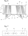
- Fig.6 in a very schematic, cut-off view, a section of an embodiment in which a straight pipe section 16 of the pipe meander 11 is assigned not just one lamella, but a lamella composite 22.
- the slat assembly 22 shown consists of three "slat layers", namely an upper slat 18a, a middle slat 18b and a lower slat 18c. All slats 18a, 18b, 18c of the slat assembly 22 have a flat, central contact area 21 with which they rest against one another. (For example, the central contact area 21 of the middle slat 18b is sandwiched between the contact areas 21 of the upper and lower slats 18a, 18c.
- At least one of the flat contact areas 21 can have a contact bead for the straight pipe section 16.
- both the upper lamella 18a and the lower lamella 18c have wings 20 which protrude from the sheet plane E at angles that are identical in pairs (but different between the lamellas 18a and 18c). In this respect, an almost *-shaped cross-sectional design of the lamella composite 22 is achieved.
- the bracket 19 consists of (threaded) receptacles 19c and 19d.
- a fastening element 15' in the form of a threaded rod can engage in these, which is fastened with its other end (not shown) to a building ceiling (not shown).
- each lamella assembly 22 of such a heat exchanger 10 can be assigned its own mounting elements 19c, 19d, so that in the present case no common frame is necessary as a mounting.
- the slats 18 according to Fig.6 in their outer area, or in the area of the wings 20, air passages or holes 27.
- These can be, for example, only These are material-preserving perforations, during the production of which no material falls off from the sheet metal blank, but the material for producing the perforation is simply removed from the wing or sheet metal plane E.
- Such perforations 27 serve in particular to conduct air through or over the heat exchanger or to generate turbulence or to improve the air conduction geometry or the like.
- Fig.6 It should be noted that the laminar assemblies 22 of such a heat exchanger could of course also be attached to the building ceiling in a different way, for example via mounting elements 19a, 19b similar to Fig.4 or by longitudinally L end-side retaining rails, as used for example in Fig.7 are indicated: This shows Fig.7 a corresponding holding rail 23 as part of a holder 19. In this holding rail 23, for example, the end regions 24 of three adjacently arranged slatted assemblies 22, as shown in Fig.6 shown.
- the holding rail 23 offers three essentially identical holding slots 25 arranged next to one another, into which the ends 24 of the composites 22 can be inserted.
- the retaining rail 23 can of course also provide corresponding receiving slots or receiving channels for the curved areas 12 of the pipe system, which in Fig.7 are indicated by dashed lines for the sake of clarity.
- Fig.8 shows in a very schematic plan view a lamella blank 26 which is still unprocessed in terms of its shape, which is designed as a rectangular sheet metal strip and almost unchanged, for example, as a middle lamella 18b in the embodiment according to Fig.6 could be used.
- this figure mainly serves to illustrate that the lamellae 18a, 18b, 18c of a lamella composite 22 or of several lamella composites 22 or also individual lamellae 18 arranged next to one another are usually all initially in the form of blanks 26, which can then be brought into a special (cross-sectional) shape, for example by a bending process.
- Fig.8 shows that the blank 26 already has holes 27.
- these can be holes that retain the material or, in the alternative embodiment not shown, holes that remove the material, in which the material is simply punched out of the raw sheet and then disposed of or something similar.
- the holes 27 can of course also have any suitable shape (in the present case they are merely designed as blind holes as an example).
- Fig.9 shows that in a section of a slat 18' a hooked nose 28 is machined out of the sheet metal. This can be produced, for example, by the same device as the holes 26 (for example with the help of a nibbling machine).
- an elongated hole 29 can then be provided, whereby the two slats 18' and 18" can be connected to one another in a form-fitting, tool-free and detachable manner by simply moving them towards one another, whereby the nose 28 can dip into the elongated hole 29 and engage behind the top of the slat 18" in a form-fitting manner.
- Fig.9 thus shows a simple way to attach two slats of a composite to each other.
- the two fins 18' and 18" can be separated from each other again at any time, in particular without tools and/or without destroying the heat exchanger 10.
- the slat 18' can be replaced with another slat of a different color (but the same shape).
- slats can of course also be attached to elements of a holder 19 in this way, for example to strips as shown in Fig.4 shown and designated 19a, 19b.
- a positive-locking, detachable, and in particular thread-free connection is preferred (although it is possible to create such connections using screw connections; however, screwless or thread-free connections are particularly preferred, as screws usually require tools such as screwdrivers or similar).
- FIGS. 10 to 14 show different designs of lamella composites with only one lamella 18, each in a very schematic sectional view, where Fig.10 essentially the embodiment according to Fig. 5b with the difference that holes 27 are provided in the area of the wings 20.
- Fig. 11 shows a configuration in which the wings 20 do not protrude but remain in the sheet plane E.
- the wings 20 are at a right angle, in the configuration according to Fig. 13 also at right angles, but aligned in different directions.
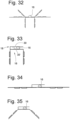
- Fig. 14 shows a special embodiment in that the lamella 18′′′ has been bent twice in the same direction and is thus shaped like a horizontal U, with two opposing, parallel contact surfaces or boundary surfaces 30 and 30' for the pipe section 16.
- this design forms a "play-off" fastening of the pipe and fin.
- the pipe can be moved in the transverse direction Q in order to simplify the assembly of the fin 18′′′ or the entire heat exchanger by allowing play (alternatively, instead of an open U-shape, a kind of closed rectangular shape can of course be achieved by further bending).
- FIGS 15 to 27 show exemplary designs of two-layer lamella composites, in which two lamellas are fixed to each other (as already mentioned above, preferably detachably and/or positively).
- the two lamellae 18 lie against each other in their flat contact areas and are fixed to each other as described above.
- one of the two lamellae 18 (or both) can have a corresponding contact bead for the pipe section 16.
- FIG. 15 to 27 illustrate that, for example, one of the lamellae can remain in the sheet plane (see, for example, Fig. 22, 26 or 27 ), the other having protruding wings (for example, protruding at an obtuse, right or acute angle).
- FIG. 15 and 23 Another special feature is the comparison of the Fig. 15 and 23 , which shows that using two identical lamellas and even an identical orientation to each other, a different appearance of a lamella composite can be achieved:
- the contact areas 21 are in accordance with Fig. 15 essentially horizontally aligned, those according to Fig. 23 essentially vertically. In this way, for example, during the assembly and/or installation of a heat exchanger, depending on the spatial situation, different, in particular optical, effects can be created by aligning the entire assembly 22 (consisting of the two fins 18) differently.
- the holding elements not shown can be provided in such a way that a differently oriented attachment is possible (for example, the end plates can also be suspended in different orientations or similar).
- Figures 28 to 32 exemplary comparable arrangements with three-layer lamella composites, i.e. composites consisting of three lamellas, which lie against each other in particular in the contact area 21 (see explanations on Fig.6 ).
- FIG. 33 to 35 There are also examples of multi-layer lamella composites, all of which have a lamella similar to Fig. 7 in which play is provided between the lamella assembly and the pipe region 16 during assembly by providing opposing, parallel contact surfaces or boundary surfaces 30, 30'.
- These lamella assemblies each consist of two lamellae (one of which has the aforementioned U-shape).
Landscapes
- Engineering & Computer Science (AREA)
- Physics & Mathematics (AREA)
- Thermal Sciences (AREA)
- Mechanical Engineering (AREA)
- General Engineering & Computer Science (AREA)
- Geometry (AREA)
- Heat-Exchange Devices With Radiators And Conduit Assemblies (AREA)
Applications Claiming Priority (1)
| Application Number | Priority Date | Filing Date | Title |
|---|---|---|---|
| DE102022131260.7A DE102022131260A1 (de) | 2022-11-25 | 2022-11-25 | Lamellenwärmetauscher, Verfahren zu dessen Herstellung und System |
Publications (2)
| Publication Number | Publication Date |
|---|---|
| EP4375604A1 true EP4375604A1 (fr) | 2024-05-29 |
| EP4375604B1 EP4375604B1 (fr) | 2026-04-29 |
Family
ID=88965113
Family Applications (1)
| Application Number | Title | Priority Date | Filing Date |
|---|---|---|---|
| EP23211761.4A Active EP4375604B1 (fr) | 2022-11-25 | 2023-11-23 | Échangeur de chaleur à ailettes, son procédé de fabrication et système |
Country Status (2)
| Country | Link |
|---|---|
| EP (1) | EP4375604B1 (fr) |
| DE (1) | DE102022131260A1 (fr) |
Cited By (1)
| Publication number | Priority date | Publication date | Assignee | Title |
|---|---|---|---|---|
| EP4663273A1 (fr) * | 2024-05-29 | 2025-12-17 | Volkswagen Ag | Dispositif de régulation de température pour un lit de sorbant, pour un dispositif de capture directe, ensemble récipient de sorbant comprenant le dispositif de régulation de température et dispositif de capture directe |
Citations (7)
| Publication number | Priority date | Publication date | Assignee | Title |
|---|---|---|---|---|
| US3379241A (en) * | 1965-04-15 | 1968-04-23 | Gen Motors Corp | Refrigerator condenser apparatus with funnel shaped flue |
| EP0009458A1 (fr) * | 1978-09-27 | 1980-04-02 | Application Des Gaz | Dispositif échangeur de température |
| US5797451A (en) * | 1994-09-01 | 1998-08-25 | Norfrost Limited | Refrigeration apparatus |
| US20070017663A1 (en) * | 2003-09-19 | 2007-01-25 | Ti Group Automotive Systems Limited | Heat exchanger cooling fin |
| US20070034364A1 (en) * | 2005-08-12 | 2007-02-15 | Cito Products, Inc. | Attachable heat radiating panel |
| US20120080174A1 (en) * | 2010-10-05 | 2012-04-05 | Frenger Systems Limited | Heat exchangers for air conditioning systems |
| EP2808638A1 (fr) * | 2013-05-28 | 2014-12-03 | Caverion Deutschland GmbH | Échangeur thermique et procédé de fixation |
Family Cites Families (4)
| Publication number | Priority date | Publication date | Assignee | Title |
|---|---|---|---|---|
| GB403899A (en) * | 1933-07-05 | 1934-01-04 | H W Dutton & Co Ltd | Improvements in and relating to radiant heat installations |
| DE29609858U1 (de) * | 1996-06-04 | 1996-08-22 | H. Krantz-Tkt Gmbh, 51465 Bergisch Gladbach | Wärmetauscherelement zum Kühlen oder Heizen eines Raumes |
| JP4856877B2 (ja) * | 2004-01-23 | 2012-01-18 | 昭和電工株式会社 | 冷房装置 |
| DE102017130081A1 (de) * | 2017-12-15 | 2019-06-19 | Krantz Gmbh | Vorrichtung zur Temperierung eines Raumes |
-
2022
- 2022-11-25 DE DE102022131260.7A patent/DE102022131260A1/de active Pending
-
2023
- 2023-11-23 EP EP23211761.4A patent/EP4375604B1/fr active Active
Patent Citations (7)
| Publication number | Priority date | Publication date | Assignee | Title |
|---|---|---|---|---|
| US3379241A (en) * | 1965-04-15 | 1968-04-23 | Gen Motors Corp | Refrigerator condenser apparatus with funnel shaped flue |
| EP0009458A1 (fr) * | 1978-09-27 | 1980-04-02 | Application Des Gaz | Dispositif échangeur de température |
| US5797451A (en) * | 1994-09-01 | 1998-08-25 | Norfrost Limited | Refrigeration apparatus |
| US20070017663A1 (en) * | 2003-09-19 | 2007-01-25 | Ti Group Automotive Systems Limited | Heat exchanger cooling fin |
| US20070034364A1 (en) * | 2005-08-12 | 2007-02-15 | Cito Products, Inc. | Attachable heat radiating panel |
| US20120080174A1 (en) * | 2010-10-05 | 2012-04-05 | Frenger Systems Limited | Heat exchangers for air conditioning systems |
| EP2808638A1 (fr) * | 2013-05-28 | 2014-12-03 | Caverion Deutschland GmbH | Échangeur thermique et procédé de fixation |
Cited By (1)
| Publication number | Priority date | Publication date | Assignee | Title |
|---|---|---|---|---|
| EP4663273A1 (fr) * | 2024-05-29 | 2025-12-17 | Volkswagen Ag | Dispositif de régulation de température pour un lit de sorbant, pour un dispositif de capture directe, ensemble récipient de sorbant comprenant le dispositif de régulation de température et dispositif de capture directe |
Also Published As
| Publication number | Publication date |
|---|---|
| DE102022131260A1 (de) | 2024-05-29 |
| EP4375604B1 (fr) | 2026-04-29 |
Similar Documents
| Publication | Publication Date | Title |
|---|---|---|
| DE202010015951U1 (de) | Flächenwärmetauscherelement | |
| EP2894411B1 (fr) | Construction de plafonds de refroidissement et procédé de montage d'un plafond chauffant et refroidissant | |
| EP4375604B1 (fr) | Échangeur de chaleur à ailettes, son procédé de fabrication et système | |
| EP4220021B1 (fr) | Déflecteur de chaleur et procédé de fabrication d'un tel déflecteur | |
| EP2295871B1 (fr) | Unité plafonnière de chauffage et/ou de refroidissement | |
| EP3786532B1 (fr) | Échangeur de chaleur de surface, système et procédé | |
| EP3103956B1 (fr) | Profile porteur modulaire comprenant des logements de barres | |
| CH639165A5 (en) | Panel element with a sound-insulating mat, in particular for soundproofing walls, soundproofing floors and soundproofing booths | |
| DE202018005716U1 (de) | Langes Fassadenpaneel | |
| DE102017102536A1 (de) | Halterung zur Befestigung einer Verkleidung an einer Gebäudewand oder -decke | |
| EP4202341A2 (fr) | Ailettes d'échangeur de chaleur et leur procédé de fabrication | |
| AT520997B1 (de) | Montagehalter | |
| EP4116630B1 (fr) | Plaque rayonnante de plafond et procédé de sa fabrication | |
| DE102010015117A1 (de) | Isolierglasscheibe | |
| EP4424210B1 (fr) | Tiroir d'étagère | |
| EP1764570A1 (fr) | Echangeur de chaleur entierement métallique | |
| DE2710652C2 (de) | Kühlzelle | |
| DE102015003279B4 (de) | Flächenwärmetauscher und Verfahren zu dessen Herstellung | |
| EP1712857A2 (fr) | Réfrigérateur et/ou congélateur | |
| CH720433A2 (de) | Wärmetauscher und Verfahren zu dessen Herstellung | |
| EP4400773A1 (fr) | Echangeur de chaleur et procédé pour son utilisation | |
| DE10337507A1 (de) | Boxensystem für Tiere, insbesondere für Rinder | |
| EP4538602A1 (fr) | Dispositif de thermorégulation d'une pièce | |
| EP4556798A1 (fr) | Plafond chauffant et/ou refroidissant et ensemble lame thermoconductrice pour celui-ci | |
| WO2008092701A1 (fr) | Dispositif d'inspection et son procédé de réalisation |
Legal Events
| Date | Code | Title | Description |
|---|---|---|---|
| PUAI | Public reference made under article 153(3) epc to a published international application that has entered the european phase |
Free format text: ORIGINAL CODE: 0009012 |
|
| STAA | Information on the status of an ep patent application or granted ep patent |
Free format text: STATUS: THE APPLICATION HAS BEEN PUBLISHED |
|
| AK | Designated contracting states |
Kind code of ref document: A1 Designated state(s): AL AT BE BG CH CY CZ DE DK EE ES FI FR GB GR HR HU IE IS IT LI LT LU LV MC ME MK MT NL NO PL PT RO RS SE SI SK SM TR |
|
| STAA | Information on the status of an ep patent application or granted ep patent |
Free format text: STATUS: REQUEST FOR EXAMINATION WAS MADE |
|
| 17P | Request for examination filed |
Effective date: 20241128 |
|
| RBV | Designated contracting states (corrected) |
Designated state(s): AL AT BE BG CH CY CZ DE DK EE ES FI FR GB GR HR HU IE IS IT LI LT LU LV MC ME MK MT NL NO PL PT RO RS SE SI SK SM TR |
|
| GRAP | Despatch of communication of intention to grant a patent |
Free format text: ORIGINAL CODE: EPIDOSNIGR1 |
|
| STAA | Information on the status of an ep patent application or granted ep patent |
Free format text: STATUS: GRANT OF PATENT IS INTENDED |
|
| RIC1 | Information provided on ipc code assigned before grant |
Ipc: F28D 1/04 20060101AFI20251127BHEP Ipc: F28F 1/22 20060101ALN20251127BHEP |
|
| INTG | Intention to grant announced |
Effective date: 20251219 |
|
| GRAS | Grant fee paid |
Free format text: ORIGINAL CODE: EPIDOSNIGR3 |
|
| GRAA | (expected) grant |
Free format text: ORIGINAL CODE: 0009210 |
|
| STAA | Information on the status of an ep patent application or granted ep patent |
Free format text: STATUS: THE PATENT HAS BEEN GRANTED |
|
| AK | Designated contracting states |
Kind code of ref document: B1 Designated state(s): AL AT BE BG CH CY CZ DE DK EE ES FI FR GB GR HR HU IE IS IT LI LT LU LV MC ME MK MT NL NO PL PT RO RS SE SI SK SM TR |
|
| REG | Reference to a national code |
Ref country code: CH Ref legal event code: F10 Free format text: ST27 STATUS EVENT CODE: U-0-0-F10-F00 (AS PROVIDED BY THE NATIONAL OFFICE) Effective date: 20260429 |