EP2295923B1 - Echangeur thermique, moteur à combustion interne et utilisation de l'échangeur thermique - Google Patents
Echangeur thermique, moteur à combustion interne et utilisation de l'échangeur thermique Download PDFInfo
- Publication number
- EP2295923B1 EP2295923B1 EP10170747.9A EP10170747A EP2295923B1 EP 2295923 B1 EP2295923 B1 EP 2295923B1 EP 10170747 A EP10170747 A EP 10170747A EP 2295923 B1 EP2295923 B1 EP 2295923B1
- Authority
- EP
- European Patent Office
- Prior art keywords
- opening
- heat exchanger
- concavity
- collar
- tube
- Prior art date
- Legal status (The legal status is an assumption and is not a legal conclusion. Google has not performed a legal analysis and makes no representation as to the accuracy of the status listed.)
- Not-in-force
Links
- 238000002485 combustion reaction Methods 0.000 title claims description 8
- 239000012530 fluid Substances 0.000 claims description 21
- 239000002826 coolant Substances 0.000 claims description 4
- 238000001816 cooling Methods 0.000 claims description 4
- 238000005259 measurement Methods 0.000 claims 2
- 238000003780 insertion Methods 0.000 description 28
- 230000037431 insertion Effects 0.000 description 28
- 229910000679 solder Inorganic materials 0.000 description 10
- 238000011161 development Methods 0.000 description 5
- 230000018109 developmental process Effects 0.000 description 5
- 238000005476 soldering Methods 0.000 description 3
- 230000015572 biosynthetic process Effects 0.000 description 2
- 238000000034 method Methods 0.000 description 2
- 230000006978 adaptation Effects 0.000 description 1
- 238000007792 addition Methods 0.000 description 1
- 239000000853 adhesive Substances 0.000 description 1
- 230000001070 adhesive effect Effects 0.000 description 1
- 230000003247 decreasing effect Effects 0.000 description 1
- 238000013461 design Methods 0.000 description 1
- 238000007373 indentation Methods 0.000 description 1
- 238000005304 joining Methods 0.000 description 1
- 239000007788 liquid Substances 0.000 description 1
- 238000004519 manufacturing process Methods 0.000 description 1
- 238000012986 modification Methods 0.000 description 1
- 230000004048 modification Effects 0.000 description 1
- 238000000926 separation method Methods 0.000 description 1
- 239000002689 soil Substances 0.000 description 1
- 238000003466 welding Methods 0.000 description 1
Images


Classifications
-
- F—MECHANICAL ENGINEERING; LIGHTING; HEATING; WEAPONS; BLASTING
- F28—HEAT EXCHANGE IN GENERAL
- F28F—DETAILS OF HEAT-EXCHANGE AND HEAT-TRANSFER APPARATUS, OF GENERAL APPLICATION
- F28F9/00—Casings; Header boxes; Auxiliary supports for elements; Auxiliary members within casings
- F28F9/02—Header boxes; End plates
- F28F9/04—Arrangements for sealing elements into header boxes or end plates
- F28F9/16—Arrangements for sealing elements into header boxes or end plates by permanent joints, e.g. by rolling
- F28F9/18—Arrangements for sealing elements into header boxes or end plates by permanent joints, e.g. by rolling by welding
-
- F—MECHANICAL ENGINEERING; LIGHTING; HEATING; WEAPONS; BLASTING
- F28—HEAT EXCHANGE IN GENERAL
- F28D—HEAT-EXCHANGE APPARATUS, NOT PROVIDED FOR IN ANOTHER SUBCLASS, IN WHICH THE HEAT-EXCHANGE MEDIA DO NOT COME INTO DIRECT CONTACT
- F28D21/00—Heat-exchange apparatus not covered by any of the groups F28D1/00 - F28D20/00
- F28D2021/0019—Other heat exchangers for particular applications; Heat exchange systems not otherwise provided for
- F28D2021/008—Other heat exchangers for particular applications; Heat exchange systems not otherwise provided for for vehicles
- F28D2021/0082—Charged air coolers
-
- F—MECHANICAL ENGINEERING; LIGHTING; HEATING; WEAPONS; BLASTING
- F28—HEAT EXCHANGE IN GENERAL
- F28D—HEAT-EXCHANGE APPARATUS, NOT PROVIDED FOR IN ANOTHER SUBCLASS, IN WHICH THE HEAT-EXCHANGE MEDIA DO NOT COME INTO DIRECT CONTACT
- F28D21/00—Heat-exchange apparatus not covered by any of the groups F28D1/00 - F28D20/00
- F28D21/0001—Recuperative heat exchangers
- F28D21/0003—Recuperative heat exchangers the heat being recuperated from exhaust gases
-
- F—MECHANICAL ENGINEERING; LIGHTING; HEATING; WEAPONS; BLASTING
- F28—HEAT EXCHANGE IN GENERAL
- F28F—DETAILS OF HEAT-EXCHANGE AND HEAT-TRANSFER APPARATUS, OF GENERAL APPLICATION
- F28F2275/00—Fastening; Joining
- F28F2275/04—Fastening; Joining by brazing
- F28F2275/045—Fastening; Joining by brazing with particular processing steps, e.g. by allowing displacement of parts during brazing or by using a reservoir for storing brazing material
-
- F—MECHANICAL ENGINEERING; LIGHTING; HEATING; WEAPONS; BLASTING
- F28—HEAT EXCHANGE IN GENERAL
- F28F—DETAILS OF HEAT-EXCHANGE AND HEAT-TRANSFER APPARATUS, OF GENERAL APPLICATION
- F28F2275/00—Fastening; Joining
- F28F2275/12—Fastening; Joining by methods involving deformation of the elements
- F28F2275/122—Fastening; Joining by methods involving deformation of the elements by crimping, caulking or clinching
Definitions
- the invention relates to a heat exchanger according to the preamble of claim 1.
- the invention begins, whose task is to provide a heat exchanger with an improved pipe-ground connection.
- an improved pipe-to-floor connection is to be made available in a heat exchanger which has an opening with a collar with an opening which widens the opening area.
- the invention also leads to an internal combustion engine with such a heat exchanger.
- a heat exchanger according to the concept of the invention has proven particularly suitable for use in the form of an exhaust gas heat exchanger, for example an exhaust gas cooler for exhaust gas cooling, in an exhaust gas recirculation system of an internal combustion engine of a motor vehicle.
- the heat exchanger according to the concept of the invention has also proved to be preferred for use as a charge air cooler for the direct or indirect cooling of charge air in a charge air supply system for an internal combustion engine of a motor vehicle.
- the first fluid is accordingly formed in particular as an exhaust gas and / or a charge air.
- the second fluid is particularly formed as a coolant or the like.
- the coolant may be liquid.
- the invention is based on the consideration that an insertion bevel facilitates the cassetting of a tube plate and a tube bundle and is fundamentally also suitable for a connection, in particular a solder connection, between a tube sheet and a holding portion of a pipe to improve.
- an insertion bevel however, can not always eliminate the transverse dimension variance of a holding section of a tube in comparison to a cross section of the opening edge formed by the actual opening passage.
- an insertion bevel extends the opening area, this can even be disadvantageous if a holding section of a pipe has an undersize.
- the tube could be easily introduced with its holding portion in the extended opening portion of the opening, but would be insufficient soldering can be, since in such a case, a distance between the holding portion of the tube and opening edge proves to be too large.
- the invention has recognized that the insertion bevel is to be provided on at least one side with a concavity that deforms to the interior of the opening region.
- the concavity allows, according to the concept of the invention, even pipes that have a section which is too small in cross section relative to the opening cross section to be reliably fixed on its holding section.
- the invention has also recognized that this fixation is made available before the soldering process and thus the soldering process itself can already take place at a reliably fixed connection between the pipe and the tube sheet.
- the opening of the bottom is formed in a heat exchanger according to the invention particularly advantageous as a passage.
- a tube collar of the passage has to an insertion bevel.
- An insertion bevel can be formed, for example, as a funnel-shaped extension of the opening area.
- an insertion bevel is arranged outwardly, ie on a side of the floor facing away from the chamber of the heat exchanger block.
- the holding portion of the tube is particularly advantageous liquid-tight in the region of the insertion, in particular metallic, connected to the collar.
- the insertion bevel is particularly well suited as a fillet with the formation of a solder deposit. In principle, a welding or adhesive or other joint connection can be used.
- the holding portion of a tube is conveniently an end-side portion of a tube and passes through the aperture so that the distal end of the tube beyond the tube bottom, i. outside the chamber, is arranged.
- a tube is particularly suitable a flat tube, such as a Mehrschlachrohr or a Einttingflachrohr - particularly suitable, for example, a B-tube or the like.
- a flat tube has a narrow side and a broad side, which is associated with a corresponding narrow side and a broad side of the opening in the ground.
- the opening of the tube plate is formed as a flat opening with a narrow side and a broad side
- the concavity only on one or only two opposite Sides of the opening is formed.
- the concept of the invention allows a self-acting during insertion of the tube compensation and adaptation of a draft contour or an opening edge on the one hand and a cross section of the tube in the holding section on the other. Overall, a joint connection between the tube sheet and the bottom can be advantageously optimized. In addition, the concept of the invention makes it possible to increase production throughput and make assembly of floor and tube bundles more reliable and easier.
- the opening of the bottom is formed as a flat opening and the concavity arranged only on two opposite narrow sides of the opening.
- the curvature can basically be carried out to varying degrees.
- the concavity partially or completely cancel the insertion bevel.
- a Einwölbungshack increases with a collar height.
- a Einwölbungshack increase with a collar height as well as a skew of the insertion bevel. This leads, in the context of a particularly preferred development, to the fact that, at least in the region of a ridge of the concavity, the collar is aligned with the opening edge formed by the actual opening passage. It may also project in the region of the ridge of the collar beyond the opening edge into a region of the actual opening passage.
- the ridge of the concavity is aligned with the opening edge or protrudes beyond this in the region of a narrow side of a flat opening.
- a flat tube with the advantages explained above can be kept very narrow or less narrow in a particularly advantageous manner.
- a collar can basically run on all sides of the opening. It has also proven to be advantageous that the collar extends only on one side or only on two opposite sides of the opening. The two opposite sides of the opening are in particular narrow sides of the opening. Accordingly, it has proven to be possible in principle that the concavity extends on all sides of the opening. In addition, it may be particularly advantageous that the concavity is arranged only on one side or, only on opposite sides of an opening. The opposite sides of the opening are in particular narrow sides of the opening.
- the collar on opposite narrow sides of an opening can be formed like a tab with a larger collar height than on a broadside of the opening. The tab is particularly well suited to carry a concavity according to the concept of the invention.
- the concavity is formed as a nose directed to the opening area.
- the nose unfolds - as a clamping nose - preferably a clamping action on an associated side of a holding portion of a tube, when it is inserted into the opening.
- the collar can have a section with no opening (ie at the distal end of the collar) without an indentation and / or an opening-near section with a concavity (ie at the proximal end of the collar).
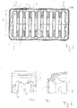
- Fig. 1 shows a heat exchanger 100 in the form of an exhaust gas cooler with a in Fig. 1 laterally open block 10 for the separate and heat exchanging guidance of a first fluid I in the form of an exhaust gas and a second fluid Il in the form of a coolant.
- the supply of Kühirnittels is present symbolically represented by an arrow for the second fluid II.
- the first fluid I is the block 10 via connection piece 20 added or removed.
- a connecting piece 20 expands from an exhaust pipe to a funnel for forming a diffuser 21, which serves for the uniform flow of a flow cross section for the first fluid I formed by flow channels 30.
- the block 10 has, in addition to a tube bundle for forming the number of flow channels 30 through which the first fluid I flows, a chamber 41 receiving the flow channels and permeable by the second fluid II in a housing 40 of the block 10, which housing 40 is shown as being open at the side.
- the block 10 also has a bottom 50 which largely separates the first fluid I and the second fluid II.
- a bottom 50 serves to connect an inflow-side diffuser 21 (bottom left in FIG Fig. 1 ) and an outflow-side diffuser 21 (upper right in the Fig. 1 )
- the different floors 50 and diffusers 21 are provided with the same reference numerals for the sake of simplicity.
- FIG. 2 the block 10 of the heat exchanger 100 with the bundle of flow channels 30, the housing 40 and the floors 50 is shown in more detail.
- the flow channels 30 are presently formed in the form of flat tubes having a in Fig. 4 have apparent narrow side 31 and broadside 32.
- Fig. 3 and Fig. 4 show in a perspective or exploded view the connection of the flat tubes 30 on one of the floors 50. From this It can be seen that a bottom 50 keeps the tubes 30 at a distance.
- an end-side holding portion H of a tube 30 is held in an opening 51 of the bottom 50 in the present case.
- the holding portion H is formed as an end-side portion which passes through the opening 51 of the bottom 50 and is thus arranged with a distal end E of the tube 30 beyond the bottom 50.
- Fig. 5 shows in plan view formed according to the concept of the invention bottom 50 with the already explained openings 51.
- the opening 51 is present for receiving a flat tube with the narrow side 31 of the flat tube associated narrow side S and one of the broad side 32 of the flat tube 30 associated broadside B in Shape of a flat opening executed.
- An opening 51 is presently formed as a passage, a in Fig. 6 (A), (B) has better recognizable collar 52.
- the collar 52 extends at its foot (proximal end) along an opening edge 53 of the opening 51 formed by the actual opening passage.
- the collar 52 opens with a Opening area - in the foot of the collar of the opening passage - widening insertion bevel 1.
- the insertion bevel 1 opens in the present funnel-shaped starting from the opening edge 53rd
- the concavity 2 is formed in such a way that it virtually eliminates the insertion bevel 1 on the narrow side S of the opening 51.
- the collar 52 is aligned with the opening edge 53 formed by the actual opening passage. In the present case, this is achieved in that the concavity the concavity 2 increases with a collar height exactly as an oblique dimension of the insertion bevel 1; These thus cancel each other out.
- the concavity 2 is only on the narrow side S of the opening 51 mounted - concretely on the opposite narrow sides S of the opening 51.
- the concavity 2 is formed in the form of a clamping nose for a flat tube 30 to be held in the opening 51.
- the clamping nose is to clamp the flat tube at its opposite narrow sides 31.
- the pipe 30 is held by the clamping nose, at least in the region of the ridge 3 of the clamping nose, frictionally.
- the tube 30 can be suitably deformed or clamped at its holding portion H, so as to adopt a shape as accurate as possible, which practically corresponds to the course of the opening edge 53.
- a pipe cross-section Q of a pipe 30 made with undersize or otherwise inaccurate would be deformed at its holding section H by the transverse forces acting from the clamping nose on the ridge 3 of the concavity 2.
- the deformation is such that the contour of the cross section Q - for example, on the broad side B of the opening 51 and / or on the narrow side S of the opening 51 - applies to the opening edge 53 and is pushed there.
- the tube 30 Due to the formation of the concavity 2 in the insertion bevel 1 of the collar 52 of the opening 51 according to the concept of the invention, the tube 30 is thus already held in the opening 51 before a solder connection.
- the solder joint to be subsequently attached in a space between the insertion 1 and holding portion H of the tube 30th be attached - the funnel-shaped course of the insertion bevel 1 forms a Lotkehle, which also serves as a solder depot. It forms a reliable and tight solder joint to ensure safe separation of the first fluid I from the second fluid II through the bottom 50.
- a compensation and the automatic adjustment of the tube cross-section Q on the contour of the opening edge 53 is according to the concept of the invention by the concavity 2 reached on the narrow side S.
Landscapes
- Engineering & Computer Science (AREA)
- Physics & Mathematics (AREA)
- Thermal Sciences (AREA)
- Mechanical Engineering (AREA)
- General Engineering & Computer Science (AREA)
- Heat-Exchange Devices With Radiators And Conduit Assemblies (AREA)
Claims (13)
- Echangeur de chaleur (100) servant à l'échange de chaleur entre un premier fluide (I) d'une part, en particulier des gaz d'échappement et / ou un air de suralimentation, et un second fluide (II) d'autre part, en particulier un moyen de refroidissement, ledit échangeur de chaleur comprenant un bloc (10) servant au guidage du premier et du second fluide (I, II), lesdits fluides étant séparés l'un de l'autre et échangeant de la chaleur,
présentant :- un certain nombre de conduits d'écoulement (30) traversés par le premier fluide (I),- une chambre (41) recevant les conduits d'écoulement (30) et traversée par le second fluide (II),- un carter (40) dans lequel sont disposés la chambre (41) et les conduits d'écoulement (30),- ainsi qu'un fond (50) séparant dans une large mesure le premier et le second fluide (I, II), lequel fond maintient à distance les conduits d'écoulement (30) conçus sous la forme de tubes plats, où- une partie de support (H) d'un tube plat est maintenue dans une ouverture (51) du fond (50), et l'ouverture (51) présente une collerette (52) ayant un chanfrein d'introduction (1) élargissant sur tous les côtés la zone d'ouverture,caractérisé en ce que
la collerette (52) présente, au niveau de l'ouverture faisant face aux petits côtés, une concavité (2) qui déforme, vers l'intérieur de la zone d'ouverture, le chanfrein d'introduction (1). - Echangeur de chaleur (100) selon la revendication 1, caractérisé en ce que la concavité (2) conserve en partie ou en totalité le chanfrein d'introduction (1).
- Echangeur de chaleur (100) selon la revendication 1 ou 2, caractérisé en ce qu'une dimension de la concavité augmente avec une hauteur de la collerette.
- Echangeur de chaleur (100) selon l'une quelconque des revendications 1 à 3, caractérisé en ce qu'une dimension de la concavité augmente avec une hauteur de la collerette, comme une dimension d'inclinaison du chanfrein d'introduction (1).
- Echangeur de chaleur (100) selon l'une quelconque des revendications 1 à 4, caractérisé en ce que, au moins dans la zone d'une nervure (3) de la concavité (2), la collerette (52) s'aligne sur le bord (53) de l'ouverture, formé par le passage réel de l'ouverture, ou bien pénètre dans une zone du passage réel de l'ouverture, au-delà du bord (53) de l'ouverture.
- Echangeur de chaleur (100) selon l'une quelconque des revendications 1 à 5, caractérisé en ce que la collerette (52) s'étend sur tous les côtés de l'ouverture (51).
- Echangeur de chaleur (100) selon l'une quelconque des revendications 1 à 6, caractérisé en ce que la collerette (52) s'étend sur un ou sur deux côtés de l'ouverture (51), en particulier seulement sur les petits côtés.
- Echangeur de chaleur (100) selon l'une quelconque des revendications 1 à 7, caractérisé en ce que la concavité (2) s'étend seulement sur un ou sur deux côtés de l'ouverture (51), en particulier seulement sur les petits côtés.
- Echangeur de chaleur (100) selon l'une quelconque des revendications 1 à 8, caractérisé en ce que la concavité (2) forme un bec dirigé vers la zone de l'ouverture, en particulier un bec de serrage pour le tube.
- Echangeur de chaleur (100) selon l'une quelconque des revendications 1 à 9, caractérisé en ce que la collerette (52) présente une partie placée loin de l'ouverture, sans concavité (2), et / ou une partie placée à proximité de l'ouverture, comportant une concavité (2).
- Moteur à combustion interne comprenant un échangeur de chaleur (100) selon l'une quelconque des revendications 1 à 10.
- Utilisation de l'échangeur de chaleur (100) selon l'une quelconque des revendications 1 à 10, comme un échangeur de chaleur de gaz d'échappement, en particulier comme un refroidisseur de gaz d'échappement servant au refroidissement de gaz d'échappement dans un système de recyclage des gaz d'échappement d'un moteur à combustion interne d'un véhicule automobile.
- Utilisation de l'échangeur de chaleur (100) selon l'une quelconque des revendications 1 à 10, comme un refroidisseur d'air de suralimentation servant au refroidissement direct ou indirect d'air de suralimentation dans un système d'alimentation en air de suralimentation pour un moteur à combustion interne d'un véhicule automobile.
Applications Claiming Priority (1)
| Application Number | Priority Date | Filing Date | Title |
|---|---|---|---|
| DE102009035089A DE102009035089A1 (de) | 2009-07-28 | 2009-07-28 | Wärmetauscher, Brennkraftmaschine und Verwendung des Wärmetauschers |
Publications (3)
| Publication Number | Publication Date |
|---|---|
| EP2295923A2 EP2295923A2 (fr) | 2011-03-16 |
| EP2295923A3 EP2295923A3 (fr) | 2014-04-23 |
| EP2295923B1 true EP2295923B1 (fr) | 2017-04-12 |
Family
ID=43037668
Family Applications (1)
| Application Number | Title | Priority Date | Filing Date |
|---|---|---|---|
| EP10170747.9A Not-in-force EP2295923B1 (fr) | 2009-07-28 | 2010-07-26 | Echangeur thermique, moteur à combustion interne et utilisation de l'échangeur thermique |
Country Status (2)
| Country | Link |
|---|---|
| EP (1) | EP2295923B1 (fr) |
| DE (1) | DE102009035089A1 (fr) |
Families Citing this family (3)
| Publication number | Priority date | Publication date | Assignee | Title |
|---|---|---|---|---|
| DE102011085479A1 (de) | 2011-10-28 | 2013-05-02 | Behr Gmbh & Co. Kg | Wärmeübertrager |
| DE102015219627A1 (de) * | 2015-10-09 | 2017-04-13 | Röchling Automotive SE & Co. KG | Frischgaszufuhrkanal |
| CN112901328A (zh) * | 2021-02-01 | 2021-06-04 | 陈首君 | 一种发动机用的虹吸式节能冷却装置 |
Family Cites Families (10)
| Publication number | Priority date | Publication date | Assignee | Title |
|---|---|---|---|---|
| DD104233A1 (fr) * | 1973-04-16 | 1974-03-05 | ||
| JPH0612229B2 (ja) * | 1986-07-29 | 1994-02-16 | Q洋ラジエ−タ−株式会社 | 熱交換器のチユ−ブ接合部 |
| DE4120442A1 (de) * | 1991-06-20 | 1992-12-24 | Thermal Waerme Kaelte Klima | Flachrohrwaermetauscher, herstellungsverfahren desselben und anwendungen |
| JPH08327283A (ja) * | 1995-05-30 | 1996-12-13 | Sanden Corp | 熱交換器の熱交換チューブ接合構造 |
| DE19844848A1 (de) * | 1998-09-30 | 2000-04-06 | Modine Mfg Co | Wärmetauscher |
| US6241144B1 (en) * | 1999-09-30 | 2001-06-05 | Caterpillar Inc. | Friction fit tab and slot shape |
| DE10016029A1 (de) | 2000-03-31 | 2001-10-04 | Modine Mfg Co | Wärmetauscher mit einer Vielzahl von Rohren |
| US6786275B2 (en) * | 2002-05-23 | 2004-09-07 | Valeo Engine Cooling | Heat exchanger header assembly |
| US7413006B2 (en) * | 2006-04-06 | 2008-08-19 | Modine Manufacturing Company | Header plate for use in a heat exchanger |
| DE102008033594A1 (de) * | 2007-07-26 | 2009-02-26 | Behr Gmbh & Co. Kg | Boden für einen Wärmetauscher |
-
2009
- 2009-07-28 DE DE102009035089A patent/DE102009035089A1/de not_active Withdrawn
-
2010
- 2010-07-26 EP EP10170747.9A patent/EP2295923B1/fr not_active Not-in-force
Non-Patent Citations (1)
| Title |
|---|
| None * |
Also Published As
| Publication number | Publication date |
|---|---|
| EP2295923A2 (fr) | 2011-03-16 |
| DE102009035089A1 (de) | 2011-02-03 |
| EP2295923A3 (fr) | 2014-04-23 |
Similar Documents
| Publication | Publication Date | Title |
|---|---|---|
| DE102006003317B4 (de) | Rohrbündel-Wärmetauscher | |
| EP0666461B2 (fr) | Raccord de tuyaux pour une boíte à eau d'un échangeur de chaleur pour véhicule automobile | |
| DE69708730T2 (de) | Wärmetauscher und Verfahren zu seiner Herstellung | |
| EP1616143B1 (fr) | Echangeur thermique, en particulier refroidisseur d'air de suralimentation pour vehicules automobiles | |
| DE102015220965A1 (de) | Indirekter Ladeluftkühler | |
| DE69203388T2 (de) | Verfahren zur Herstellung eines Rohrbündelwärmetauschers. | |
| DE102014202447A1 (de) | Abgaswärmeübertrager | |
| WO2004001203A2 (fr) | Echangeur thermique pour gaz d'echappement et procede de fabrication associe | |
| EP0276483B1 (fr) | Raccord de tuyaux, notamment pour évaporateur à tube aplati | |
| EP2295923B1 (fr) | Echangeur thermique, moteur à combustion interne et utilisation de l'échangeur thermique | |
| EP2028431A2 (fr) | Tuyau plat à plusieurs chambres, échangeur thermique et utilisation d'un échangeur thermique | |
| DE102006031606A1 (de) | Wärmetauscher zur Abgaskühlung, Verfahren zur Herstellung eines Wärmetauschers | |
| DE2449079A1 (de) | Waermeaustauscher mit an den kleinen seiten der rohrplatten desselben befestigten seitenteilen | |
| DE102017220390A1 (de) | Wärmeübertrager und zugehöriges Herstellungsverfahren | |
| DE102008047076A1 (de) | Fügebauteil und Wärmetauscher | |
| EP1668304A1 (fr) | Unite d'echange thermique pour vehicules automobiles | |
| DE102008028244B3 (de) | Abgaswärmetauscher | |
| DE102005043093A1 (de) | Wärmetauscherrohr | |
| DE10338382B4 (de) | Krümmer für eine Brennkraftmaschine und Verfahren zu dessen Herstellung | |
| DE102015219653A1 (de) | Diffusor für einen Wärmeübertrager | |
| DE102014219208A1 (de) | Wärmeübertrager | |
| DE102013008773A1 (de) | Wärmetauscher, insbesondere Abgaswärmetauscher oder Ladeluftkühler | |
| DE102008015223A1 (de) | Vorrichtung zur Abgasrückführung und Verfahren zu deren Herstellung | |
| DE202010015200U1 (de) | Wärmetauscher | |
| EP0826933B9 (fr) | Méthode pour raccorder des radiateurs |
Legal Events
| Date | Code | Title | Description |
|---|---|---|---|
| PUAI | Public reference made under article 153(3) epc to a published international application that has entered the european phase |
Free format text: ORIGINAL CODE: 0009012 |
|
| AK | Designated contracting states |
Kind code of ref document: A2 Designated state(s): AL AT BE BG CH CY CZ DE DK EE ES FI FR GB GR HR HU IE IS IT LI LT LU LV MC MK MT NL NO PL PT RO SE SI SK SM TR |
|
| AX | Request for extension of the european patent |
Extension state: BA ME RS |
|
| PUAL | Search report despatched |
Free format text: ORIGINAL CODE: 0009013 |
|
| AK | Designated contracting states |
Kind code of ref document: A3 Designated state(s): AL AT BE BG CH CY CZ DE DK EE ES FI FR GB GR HR HU IE IS IT LI LT LU LV MC MK MT NL NO PL PT RO SE SI SK SM TR |
|
| AX | Request for extension of the european patent |
Extension state: BA ME RS |
|
| RIC1 | Information provided on ipc code assigned before grant |
Ipc: F28F 9/18 20060101AFI20140314BHEP Ipc: F28D 21/00 20060101ALI20140314BHEP |
|
| 17P | Request for examination filed |
Effective date: 20141023 |
|
| RBV | Designated contracting states (corrected) |
Designated state(s): AL AT BE BG CH CY CZ DE DK EE ES FI FR GB GR HR HU IE IS IT LI LT LU LV MC MK MT NL NO PL PT RO SE SI SK SM TR |
|
| RAP1 | Party data changed (applicant data changed or rights of an application transferred) |
Owner name: MAHLE BEHR GMBH & CO. KG |
|
| GRAP | Despatch of communication of intention to grant a patent |
Free format text: ORIGINAL CODE: EPIDOSNIGR1 |
|
| RIC1 | Information provided on ipc code assigned before grant |
Ipc: F28F 9/18 20060101AFI20160923BHEP Ipc: F28D 21/00 20060101ALI20160923BHEP |
|
| INTG | Intention to grant announced |
Effective date: 20161019 |
|
| GRAJ | Information related to disapproval of communication of intention to grant by the applicant or resumption of examination proceedings by the epo deleted |
Free format text: ORIGINAL CODE: EPIDOSDIGR1 |
|
| GRAR | Information related to intention to grant a patent recorded |
Free format text: ORIGINAL CODE: EPIDOSNIGR71 |
|
| GRAS | Grant fee paid |
Free format text: ORIGINAL CODE: EPIDOSNIGR3 |
|
| GRAA | (expected) grant |
Free format text: ORIGINAL CODE: 0009210 |
|
| INTC | Intention to grant announced (deleted) | ||
| RIN1 | Information on inventor provided before grant (corrected) |
Inventor name: GHIANI, FRANCO |
|
| INTG | Intention to grant announced |
Effective date: 20170302 |
|
| AK | Designated contracting states |
Kind code of ref document: B1 Designated state(s): AL AT BE BG CH CY CZ DE DK EE ES FI FR GB GR HR HU IE IS IT LI LT LU LV MC MK MT NL NO PL PT RO SE SI SK SM TR |
|
| REG | Reference to a national code |
Ref country code: GB Ref legal event code: FG4D Free format text: NOT ENGLISH |
|
| REG | Reference to a national code |
Ref country code: CH Ref legal event code: EP |
|
| REG | Reference to a national code |
Ref country code: IE Ref legal event code: FG4D Free format text: LANGUAGE OF EP DOCUMENT: GERMAN |
|
| REG | Reference to a national code |
Ref country code: AT Ref legal event code: REF Ref document number: 884345 Country of ref document: AT Kind code of ref document: T Effective date: 20170515 |
|
| REG | Reference to a national code |
Ref country code: DE Ref legal event code: R096 Ref document number: 502010013446 Country of ref document: DE |
|
| REG | Reference to a national code |
Ref country code: FR Ref legal event code: PLFP Year of fee payment: 8 |
|
| REG | Reference to a national code |
Ref country code: NL Ref legal event code: MP Effective date: 20170412 |
|
| REG | Reference to a national code |
Ref country code: LT Ref legal event code: MG4D |
|
| PG25 | Lapsed in a contracting state [announced via postgrant information from national office to epo] |
Ref country code: NL Free format text: LAPSE BECAUSE OF FAILURE TO SUBMIT A TRANSLATION OF THE DESCRIPTION OR TO PAY THE FEE WITHIN THE PRESCRIBED TIME-LIMIT Effective date: 20170412 |
|
| PG25 | Lapsed in a contracting state [announced via postgrant information from national office to epo] |
Ref country code: NO Free format text: LAPSE BECAUSE OF FAILURE TO SUBMIT A TRANSLATION OF THE DESCRIPTION OR TO PAY THE FEE WITHIN THE PRESCRIBED TIME-LIMIT Effective date: 20170712 Ref country code: GR Free format text: LAPSE BECAUSE OF FAILURE TO SUBMIT A TRANSLATION OF THE DESCRIPTION OR TO PAY THE FEE WITHIN THE PRESCRIBED TIME-LIMIT Effective date: 20170713 Ref country code: LT Free format text: LAPSE BECAUSE OF FAILURE TO SUBMIT A TRANSLATION OF THE DESCRIPTION OR TO PAY THE FEE WITHIN THE PRESCRIBED TIME-LIMIT Effective date: 20170412 Ref country code: FI Free format text: LAPSE BECAUSE OF FAILURE TO SUBMIT A TRANSLATION OF THE DESCRIPTION OR TO PAY THE FEE WITHIN THE PRESCRIBED TIME-LIMIT Effective date: 20170412 Ref country code: ES Free format text: LAPSE BECAUSE OF FAILURE TO SUBMIT A TRANSLATION OF THE DESCRIPTION OR TO PAY THE FEE WITHIN THE PRESCRIBED TIME-LIMIT Effective date: 20170412 Ref country code: HR Free format text: LAPSE BECAUSE OF FAILURE TO SUBMIT A TRANSLATION OF THE DESCRIPTION OR TO PAY THE FEE WITHIN THE PRESCRIBED TIME-LIMIT Effective date: 20170412 |
|
| PG25 | Lapsed in a contracting state [announced via postgrant information from national office to epo] |
Ref country code: LV Free format text: LAPSE BECAUSE OF FAILURE TO SUBMIT A TRANSLATION OF THE DESCRIPTION OR TO PAY THE FEE WITHIN THE PRESCRIBED TIME-LIMIT Effective date: 20170412 Ref country code: BG Free format text: LAPSE BECAUSE OF FAILURE TO SUBMIT A TRANSLATION OF THE DESCRIPTION OR TO PAY THE FEE WITHIN THE PRESCRIBED TIME-LIMIT Effective date: 20170712 Ref country code: SE Free format text: LAPSE BECAUSE OF FAILURE TO SUBMIT A TRANSLATION OF THE DESCRIPTION OR TO PAY THE FEE WITHIN THE PRESCRIBED TIME-LIMIT Effective date: 20170412 Ref country code: PL Free format text: LAPSE BECAUSE OF FAILURE TO SUBMIT A TRANSLATION OF THE DESCRIPTION OR TO PAY THE FEE WITHIN THE PRESCRIBED TIME-LIMIT Effective date: 20170412 Ref country code: IS Free format text: LAPSE BECAUSE OF FAILURE TO SUBMIT A TRANSLATION OF THE DESCRIPTION OR TO PAY THE FEE WITHIN THE PRESCRIBED TIME-LIMIT Effective date: 20170812 |
|
| REG | Reference to a national code |
Ref country code: DE Ref legal event code: R097 Ref document number: 502010013446 Country of ref document: DE |
|
| PG25 | Lapsed in a contracting state [announced via postgrant information from national office to epo] |
Ref country code: EE Free format text: LAPSE BECAUSE OF FAILURE TO SUBMIT A TRANSLATION OF THE DESCRIPTION OR TO PAY THE FEE WITHIN THE PRESCRIBED TIME-LIMIT Effective date: 20170412 Ref country code: CZ Free format text: LAPSE BECAUSE OF FAILURE TO SUBMIT A TRANSLATION OF THE DESCRIPTION OR TO PAY THE FEE WITHIN THE PRESCRIBED TIME-LIMIT Effective date: 20170412 Ref country code: SK Free format text: LAPSE BECAUSE OF FAILURE TO SUBMIT A TRANSLATION OF THE DESCRIPTION OR TO PAY THE FEE WITHIN THE PRESCRIBED TIME-LIMIT Effective date: 20170412 Ref country code: RO Free format text: LAPSE BECAUSE OF FAILURE TO SUBMIT A TRANSLATION OF THE DESCRIPTION OR TO PAY THE FEE WITHIN THE PRESCRIBED TIME-LIMIT Effective date: 20170412 Ref country code: DK Free format text: LAPSE BECAUSE OF FAILURE TO SUBMIT A TRANSLATION OF THE DESCRIPTION OR TO PAY THE FEE WITHIN THE PRESCRIBED TIME-LIMIT Effective date: 20170412 |
|
| PLBE | No opposition filed within time limit |
Free format text: ORIGINAL CODE: 0009261 |
|
| STAA | Information on the status of an ep patent application or granted ep patent |
Free format text: STATUS: NO OPPOSITION FILED WITHIN TIME LIMIT |
|
| PG25 | Lapsed in a contracting state [announced via postgrant information from national office to epo] |
Ref country code: SM Free format text: LAPSE BECAUSE OF FAILURE TO SUBMIT A TRANSLATION OF THE DESCRIPTION OR TO PAY THE FEE WITHIN THE PRESCRIBED TIME-LIMIT Effective date: 20170412 Ref country code: IT Free format text: LAPSE BECAUSE OF FAILURE TO SUBMIT A TRANSLATION OF THE DESCRIPTION OR TO PAY THE FEE WITHIN THE PRESCRIBED TIME-LIMIT Effective date: 20170412 |
|
| REG | Reference to a national code |
Ref country code: CH Ref legal event code: PL |
|
| 26N | No opposition filed |
Effective date: 20180115 |
|
| GBPC | Gb: european patent ceased through non-payment of renewal fee |
Effective date: 20170726 |
|
| REG | Reference to a national code |
Ref country code: IE Ref legal event code: MM4A |
|
| PG25 | Lapsed in a contracting state [announced via postgrant information from national office to epo] |
Ref country code: CH Free format text: LAPSE BECAUSE OF NON-PAYMENT OF DUE FEES Effective date: 20170731 Ref country code: LI Free format text: LAPSE BECAUSE OF NON-PAYMENT OF DUE FEES Effective date: 20170731 Ref country code: GB Free format text: LAPSE BECAUSE OF NON-PAYMENT OF DUE FEES Effective date: 20170726 Ref country code: IE Free format text: LAPSE BECAUSE OF NON-PAYMENT OF DUE FEES Effective date: 20170726 |
|
| PG25 | Lapsed in a contracting state [announced via postgrant information from national office to epo] |
Ref country code: SI Free format text: LAPSE BECAUSE OF FAILURE TO SUBMIT A TRANSLATION OF THE DESCRIPTION OR TO PAY THE FEE WITHIN THE PRESCRIBED TIME-LIMIT Effective date: 20170412 |
|
| REG | Reference to a national code |
Ref country code: BE Ref legal event code: MM Effective date: 20170731 |
|
| PG25 | Lapsed in a contracting state [announced via postgrant information from national office to epo] |
Ref country code: LU Free format text: LAPSE BECAUSE OF NON-PAYMENT OF DUE FEES Effective date: 20170726 |
|
| REG | Reference to a national code |
Ref country code: FR Ref legal event code: PLFP Year of fee payment: 9 |
|
| PG25 | Lapsed in a contracting state [announced via postgrant information from national office to epo] |
Ref country code: BE Free format text: LAPSE BECAUSE OF NON-PAYMENT OF DUE FEES Effective date: 20170731 |
|
| REG | Reference to a national code |
Ref country code: AT Ref legal event code: MM01 Ref document number: 884345 Country of ref document: AT Kind code of ref document: T Effective date: 20170726 |
|
| PG25 | Lapsed in a contracting state [announced via postgrant information from national office to epo] |
Ref country code: MT Free format text: LAPSE BECAUSE OF FAILURE TO SUBMIT A TRANSLATION OF THE DESCRIPTION OR TO PAY THE FEE WITHIN THE PRESCRIBED TIME-LIMIT Effective date: 20170412 |
|
| PGFP | Annual fee paid to national office [announced via postgrant information from national office to epo] |
Ref country code: FR Payment date: 20180724 Year of fee payment: 9 Ref country code: DE Payment date: 20180730 Year of fee payment: 9 |
|
| PG25 | Lapsed in a contracting state [announced via postgrant information from national office to epo] |
Ref country code: AT Free format text: LAPSE BECAUSE OF NON-PAYMENT OF DUE FEES Effective date: 20170726 |
|
| PG25 | Lapsed in a contracting state [announced via postgrant information from national office to epo] |
Ref country code: MC Free format text: LAPSE BECAUSE OF FAILURE TO SUBMIT A TRANSLATION OF THE DESCRIPTION OR TO PAY THE FEE WITHIN THE PRESCRIBED TIME-LIMIT Effective date: 20170412 Ref country code: HU Free format text: LAPSE BECAUSE OF FAILURE TO SUBMIT A TRANSLATION OF THE DESCRIPTION OR TO PAY THE FEE WITHIN THE PRESCRIBED TIME-LIMIT; INVALID AB INITIO Effective date: 20100726 |
|
| PG25 | Lapsed in a contracting state [announced via postgrant information from national office to epo] |
Ref country code: CY Free format text: LAPSE BECAUSE OF NON-PAYMENT OF DUE FEES Effective date: 20170412 |
|
| PG25 | Lapsed in a contracting state [announced via postgrant information from national office to epo] |
Ref country code: MK Free format text: LAPSE BECAUSE OF FAILURE TO SUBMIT A TRANSLATION OF THE DESCRIPTION OR TO PAY THE FEE WITHIN THE PRESCRIBED TIME-LIMIT Effective date: 20170412 |
|
| REG | Reference to a national code |
Ref country code: DE Ref legal event code: R119 Ref document number: 502010013446 Country of ref document: DE |
|
| PG25 | Lapsed in a contracting state [announced via postgrant information from national office to epo] |
Ref country code: TR Free format text: LAPSE BECAUSE OF FAILURE TO SUBMIT A TRANSLATION OF THE DESCRIPTION OR TO PAY THE FEE WITHIN THE PRESCRIBED TIME-LIMIT Effective date: 20170412 |
|
| PG25 | Lapsed in a contracting state [announced via postgrant information from national office to epo] |
Ref country code: DE Free format text: LAPSE BECAUSE OF NON-PAYMENT OF DUE FEES Effective date: 20200201 |
|
| PG25 | Lapsed in a contracting state [announced via postgrant information from national office to epo] |
Ref country code: PT Free format text: LAPSE BECAUSE OF FAILURE TO SUBMIT A TRANSLATION OF THE DESCRIPTION OR TO PAY THE FEE WITHIN THE PRESCRIBED TIME-LIMIT Effective date: 20170412 |
|
| PG25 | Lapsed in a contracting state [announced via postgrant information from national office to epo] |
Ref country code: FR Free format text: LAPSE BECAUSE OF NON-PAYMENT OF DUE FEES Effective date: 20190731 |
|
| PG25 | Lapsed in a contracting state [announced via postgrant information from national office to epo] |
Ref country code: AL Free format text: LAPSE BECAUSE OF FAILURE TO SUBMIT A TRANSLATION OF THE DESCRIPTION OR TO PAY THE FEE WITHIN THE PRESCRIBED TIME-LIMIT Effective date: 20170412 |