EP2296006B1 - Breitband-Flugzeugradarvorrichtung mit großem Erfassungswinkel, insbesondere für die Funktion der Kollisionsvermeidung - Google Patents
Breitband-Flugzeugradarvorrichtung mit großem Erfassungswinkel, insbesondere für die Funktion der Kollisionsvermeidung Download PDFInfo
- Publication number
- EP2296006B1 EP2296006B1 EP10176415.7A EP10176415A EP2296006B1 EP 2296006 B1 EP2296006 B1 EP 2296006B1 EP 10176415 A EP10176415 A EP 10176415A EP 2296006 B1 EP2296006 B1 EP 2296006B1
- Authority
- EP
- European Patent Office
- Prior art keywords
- transmission
- frequency
- waveform
- distance
- radar device
- Prior art date
- Legal status (The legal status is an assumption and is not a legal conclusion. Google has not performed a legal analysis and makes no representation as to the accuracy of the status listed.)
- Active
Links
Images



Classifications
-
- G—PHYSICS
- G01—MEASURING; TESTING
- G01S—RADIO DIRECTION-FINDING; RADIO NAVIGATION; DETERMINING DISTANCE OR VELOCITY BY USE OF RADIO WAVES; LOCATING OR PRESENCE-DETECTING BY USE OF THE REFLECTION OR RERADIATION OF RADIO WAVES; ANALOGOUS ARRANGEMENTS USING OTHER WAVES
- G01S13/00—Systems using the reflection or reradiation of radio waves, e.g. radar systems; Analogous systems using reflection or reradiation of waves whose nature or wavelength is irrelevant or unspecified
- G01S13/02—Systems using reflection of radio waves, e.g. primary radar systems; Analogous systems
- G01S13/06—Systems determining position data of a target
- G01S13/42—Simultaneous measurement of distance and other co-ordinates
- G01S13/426—Scanning radar, e.g. 3D radar
-
- G—PHYSICS
- G01—MEASURING; TESTING
- G01S—RADIO DIRECTION-FINDING; RADIO NAVIGATION; DETERMINING DISTANCE OR VELOCITY BY USE OF RADIO WAVES; LOCATING OR PRESENCE-DETECTING BY USE OF THE REFLECTION OR RERADIATION OF RADIO WAVES; ANALOGOUS ARRANGEMENTS USING OTHER WAVES
- G01S13/00—Systems using the reflection or reradiation of radio waves, e.g. radar systems; Analogous systems using reflection or reradiation of waves whose nature or wavelength is irrelevant or unspecified
- G01S13/66—Radar-tracking systems; Analogous systems
- G01S13/72—Radar-tracking systems; Analogous systems for two-dimensional [2D] tracking, e.g. combination of angle and range tracking, track-while-scan radar
-
- G—PHYSICS
- G01—MEASURING; TESTING
- G01S—RADIO DIRECTION-FINDING; RADIO NAVIGATION; DETERMINING DISTANCE OR VELOCITY BY USE OF RADIO WAVES; LOCATING OR PRESENCE-DETECTING BY USE OF THE REFLECTION OR RERADIATION OF RADIO WAVES; ANALOGOUS ARRANGEMENTS USING OTHER WAVES
- G01S13/00—Systems using the reflection or reradiation of radio waves, e.g. radar systems; Analogous systems using reflection or reradiation of waves whose nature or wavelength is irrelevant or unspecified
- G01S13/88—Radar or analogous systems specially adapted for specific applications
- G01S13/93—Radar or analogous systems specially adapted for specific applications for anti-collision purposes
- G01S13/933—Radar or analogous systems specially adapted for specific applications for anti-collision purposes of aircraft or spacecraft
-
- G—PHYSICS
- G01—MEASURING; TESTING
- G01S—RADIO DIRECTION-FINDING; RADIO NAVIGATION; DETERMINING DISTANCE OR VELOCITY BY USE OF RADIO WAVES; LOCATING OR PRESENCE-DETECTING BY USE OF THE REFLECTION OR RERADIATION OF RADIO WAVES; ANALOGOUS ARRANGEMENTS USING OTHER WAVES
- G01S13/00—Systems using the reflection or reradiation of radio waves, e.g. radar systems; Analogous systems using reflection or reradiation of waves whose nature or wavelength is irrelevant or unspecified
- G01S13/02—Systems using reflection of radio waves, e.g. primary radar systems; Analogous systems
- G01S2013/0236—Special technical features
- G01S2013/0245—Radar with phased array antenna
- G01S2013/0254—Active array antenna
Definitions
- the present invention relates to an airborne radar with wide angular coverage, in particular for the obstacle detection and avoidance function equipping for example drones.
- a technical problem concerns the realization of a radar function of non-cooperative detection of aerial obstacles for aircraft, in particular for drones. This function is essential to allow the insertion of autopiloted aircraft in the non-segregated airspace. She participates in the obstacle avoidance function known as "Sense & Avoid”.
- Such a radar must have a very large field of view (typically ⁇ 110 ° in azimuth and ⁇ 15 ° in elevation) and must be able to scan the space in a very short time, of the order of magnitude of the second, given the time required to engage an avoidance maneuver in the presence of risk of collision. These characteristics roughly correspond to the environmental observation capacity of a "human” pilot required for a "See & Avoid” function.
- This solution is conventionally implemented using antenna arrays whose diagrams formed must have sufficient directivity to locate the targets with good accuracy.
- the relative radial velocity VRR is counted positive when it corresponds to a rimpedement of the target.
- a document US 2006/197699 A1 describes an active module integrated into an electronic scanning antenna equipping an airborne radar.
- a document MALMQVIST AND AL "On the Use of MEMS Phase Shifters in a Low-Cost Ka-band Multifunctional ESA on Small UAVs", MICROWAVE CONFERENCE, 2007, APMC 2007, ASIA-PACIFIC; IEEE, PISCATAWAY, NJ, USA, December 11, 2007, pages 1-4 a multifunctional electronic scanning antenna equipping an airborne radar device.
- the transmission system comprises at least two waveform generators, a first waveform generator providing a signal at a first frequency F1 and a second waveform generator providing a signal at a second frequency F2, each transmission network being separated into two sub-networks, the radiating elements of the first sub-network being fed by the signal at the first frequency F1 and the radiating elements of the second sub-network being fed by the signal at the second frequency F2, the colored emission being obtained by transmitting on the first sub-network. network at the first frequency F1 and transmitting on the second subnet at the second frequency F2.
- the processing means of the reception system perform, for example, in the elevation plane, the calculation of a sum channel d'and a difference channel ⁇ according to the monopulse technique from the received signals of firstly at the first frequency F1 and secondly at the second frequency F2.
- a radar uses for example two waveforms, a wave generator providing two waveforms, a first waveform being adapted to fast targets and localized in Doppler frequency or in distance measurement. on thermal noise, the second reduced-range waveform being adapted to detectable slow targets against the background of soil clutter.
- the first waveform is for example a continuous sine wave.
- the first waveform uses at least two frequency shifted continuous waves of k / T where T is the Doppler integration time and k a relative integer not bad.
- the first waveform uses, for example, as a window for weighting the Fourier transforms in reception of polynomials of sine or cosine functions of any order.
- the ambiguity in angle and distance measurements resulting from the use of the first emission-stained waveform is, for example, raised by emitting sinusoidal waves spaced apart by a plurality of frequency deviations.
- frequency differences ⁇ F are used between transmission networks of opposite signs. These frequency deviations have, for example, substantially the same absolute value.
- the ambiguity removal in angle and distance measurements, for the first waveform is carried out first by raising the ambiguity rank over the distance by the use of the plurality of frequency deviations.
- the ambiguity of the angle and distance measurements, for the first waveform is eliminated for example in the least squares sense when the distance ambiguity rank is raised.
- the second waveform is a pulsed sine wave.
- the colored emission of the second waveform for example uses the emission of at least two pulsed sine waves of frequency-shifted carrier frequencies F1, F2 of k / T where T is the Doppler integration time and k a nonzero relative integer.
- the colored emission of the second waveform uses the emission of at least two pulsed sine waves of frequency shifted carriers of FR / q where FR is the frequency of repetition of the pulses and q a nonzero positive integer, the parameter q being for example equal to 2.
- emission staining can be used.
- the colored emission of the second waveform may use the emission of at least two pulsed sine waves of frequency shifted carriers substantially twice the Doppler frequency spread of the ground clutter.
- the colored emission of the second waveform may use the emission of at least two pulsed sine waves of frequency shifted carriers substantially twice the maximum Doppler frequency of the ground clutter in the axis of the carrier aircraft said radar device.
- the colored emission of the second waveform can use the emission of at least two pulsed sine waves of frequency-shifted carriers of one frequency. deviation ⁇ F, the sign of this difference being permuted from one fast FFT Fourier transform sequence to the next.
- the colored emission of the second waveform can use the emission of at least two pulsed sine waves of frequency-shifted carriers of one frequency. difference ⁇ F, the absolute value of this difference being switched from N FFT sequences to N FFT sequences, the number N being for example equal to 2.
- the colored emission of the second waveform may use the emission of at least two pulsed sine waves modulated by orthogonal phase codes.
- the colored emission of the second waveform for example uses the emission of at least two pulsed sinusoidal waves modulated by orthogonal phase codes obtained by time reversal of one with respect to the other.
- the colored emission of the second waveform can use the emission of at least two pulsed sine waves modulated by identical Barker codes but inverted in time.
- the second waveform uses, for example, as a window for weighting the Fourier transforms in reception of polynomials of any order having sinus or cosine functions as variables.
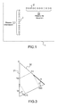
- the figure 1 illustrates the principle of realization of an antenna system used in a radar according to the invention.
- This system comprises two networks 11, 12 of radiating elements 2, each forming an elementary source on transmission and an elementary receiver on reception. They are made in the same technology, for example metal pellets, also called "patch”.
- a network 11 is used for transmission and the other network 12 is used for reception. More particularly, the first network 11 is used to focus the antenna beam in a transmission plane, by beamforming by calculation. The second network 12 is used to focus the antenna beam on reception in the plane orthogonal to the preceding plane, by beamforming by calculation.
- the network antenna 1 therefore comprises a network 11 in column for transmission, arranged vertically, and a network 12 in line for reception, arranged horizontally.
- the arrays 11, 12 may be spaced from each other and placed in any manner provided that the sighting directions of the radiating elements 2 are close and their radiation patterns are close.
- the antenna arrays 11, 12 may advantageously be printed circuit, thus enabling a low cost realization.
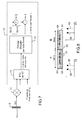
- the figure 2 illustrates an exemplary embodiment of a transmission and reception system of a radar according to the invention, using an antenna system according to the principle of realization of the figure 1 .
- the transmission part 21 comprises, for example, three linear transmission networks 111, 112, 113 of the type of that 11 of the figure 1 . These networks are switched electronically by switches 23, 24. Each network is divided into two sub-networks 23, 24 forming for example an upper part 23 and a lower part 24 insofar as the antenna is arranged substantially vertically.
- the first sub-networks 23 are for example powered by a sinusoidal signal having a first frequency F1 and the second sub-networks 24 are for example powered by a sinusoidal signal having a second frequency F2.
- the signals are provided by waveform generators 25, 26 via unrepresented power amplifiers.
- Switches 27, 28 make it possible to switch the signals coming from the generators 27, 28 towards one or the other network.
- a pair of switches is assigned to each network 111, 112, 113, only one pair of switches is represented in figure 2 .
- the emission is colored to realize the MIMO principle with N simple signals to generate.
- a radar according to the invention also comprises unrepresented processing means performing calculations of detection and location of targets according to modes of operation which will be described later.
- the figure 3 illustrates an example of a collision or near-collision trajectory.
- a point P represents a carrier at speed V p , a point I representing an intruder, the target, at the speed V i .
- the position of the points P and I is a function of the time t, they are represented on the figure 3 at a time t0.
- Point C represents the point of collision.
- a necessary condition of collision is that straight line PI must belong to the plane generated by the two velocity vectors.
- the half-lines 31, 32 of respective origins P and I respectively carried by the velocity vectors V p and V i must have a non-zero intersection.
- ⁇ are respectively the angles between the PI and PC segments and between the PI and IC segments.
- ⁇ is the azimuth angle under which the target I is seen from the carrier P.
- the relative radial velocity VRR is constant and positive, in approximation.
- T R V ⁇ R ⁇ R .
- the figure 4 shows, by curves representative of the equation (5), the places accessible to a collision for different target speeds, a place being defined by the pair ( VRR , ⁇ ), the places being parameterized by the speed Vi of the target .
- the curves 41, 42, 43, 44, 45 represent the speed VRR as a function of the azimuth angle according to equation (5) above. Each curve corresponds to a target speed Vi .
- the detection is exo-clutter at low azimuth and endo-clutter at high azimuth.
- the criterion for using one or the other waveform is, among other reasons, based on the speed of the carrier and that of the target sought.
- the radar emits at least two continuous sinusoidal waves orthogonal to each other during a treatment cycle of duration T.
- two waves are emitted, one at the frequency F1 and the other at the frequency F2, the signal at F1 being emitted by the first waveform generator 25 and the signal at F2 being emitted by the second generator of 26.
- each treatment cycle is relatively long, of the order of 50 ms for example. This makes it possible to obtain a very high Doppler frequency separating power, typically less than 1 m / s in X band.
- the signals transmitted to F1 and F2 to the target are separated upon reception by their orthogonality property.
- this separation is advantageously carried out by Fourier Transform (FFT) over the previous duration T because one can group in the same operator channel separation and Doppler filtering.
- FFT Fourier Transform
- N FFT is the number of samples of each signal F1 or F2 contained in the window of duration T.
- weighting polynomials are, for example, the windows of Hanning, Hamming, Blackmann, etc. or " Ad-Hoc " windows. They are well known to those skilled in the art.
- the figure 5 represents an antenna element of the transmission part, more precisely it represents a network 111 of the light emission part a target 51 at a distance R much greater than 2a, a being the half-length of a sub-network 23, 24.
- the first sub-network 23, powered by the first generator 25, transmits a continuous sinusoidal signal at the frequency F 1 F + ⁇ F / 2.
- the second subarray 24, powered by the second generator 26, transmits a sinusoidal signal at the frequency F 2 F - ⁇ F / 2 .
- the phase center of the receiving device 22 is located at the origin point O. Any other nearby location would result in the same practical result.
- the "useful" information is contained in the differential phase, obtained for example by calculating the covariance argument S 1 .
- the distance ambiguity is 3 km.
- the distance ambiguity is 1875 km; however, at 10 km, the bias is 1.8 ° and needs to be corrected.
- the weighting is applied globally on both emission subnetworks.
- the separate use of the signals from each sub-network, as in the first case, does not make it possible to take advantage of this weighting.
- the watch is performed with a waveform allowing the formation of ⁇ and ⁇ channels, to avoid detecting strong SER echoes by the side lobes of the antennal device.
- the Figures 6a and 6b illustrate exemplary spectral configurations respectively when the frequency offset ⁇ F between the frequencies F1 and F2, respectively is much lower than 1 kHz and above 33 kHz.
- the Doppler domain of the targets 61, 62 and the ground clutter 63, 64 is convoluted by each of the carriers 65, 66 with frequencies F1 and F2.
- a first clutter 63 and a first Doppler band 61 correspond to the frequency carrier F1 emitted by the first sub-network 23
- a second clutter 64 and a second Doppler band 62 correspond to the frequency carrier F2 transmitted by the second sub-network. 24.
- Two ⁇ F difference choices are possible for this first "exo-clutter" waveform.
- the figure 6a illustrates the first choice where the difference ⁇ F is much lower than the soil clutter band so as not to unnecessarily increase the "endo-clutter" zone.
- ⁇ F values of the order of a hundred or a few hundred Hz.
- the figure 6b illustrates the second choice where the deviation ⁇ F is greater than the total band of target echoes and clutter.
- the deviation ⁇ F is greater than the total band of target echoes and clutter.
- the first configuration leads to a weak coupling of the distance on the angle and allows to separate only the echoes of targets out of clutter zone then, on the contrary, it is very strong in the second configuration, illustrated by the figure 6b , but allows to separate all signals, clutter and targets.
- the time of exploration and tracking of the targets of the "wide range, high speed" domain, corresponding to this first waveform is of the order of one second, for example 900 milliseconds, to ensure correct tracking. dangerous targets.
- This domain is for example subdivided into three elevation subdomains, each subdomain being covered by a transmission network 111, 112, 113 as illustrated. over there figure 2 .
- the antenna beams are shifted between them.
- the first network 111 covers, for example, the subdomain -15 ° to -5 °
- the second network 112 for example covers the subdomain -5 ° to + 5 °
- the third network 113 covers, for example, the subdomain + 5 ° to + 15 °.
- Each subdomain is therefore explored and the targets continued for example about 300 milliseconds.
- the total observation time can be subdivided into, for example, six Doppler integration intervals of approximately 50 milliseconds each.
- the figure 7 illustrates a possible mimic of reception in standby mode.
- the received signal s (t) on a reception channel represented by a source 2 of the reception network 12, is mixed by a microwave mixer 71 with the central frequency F issued for example from one of the waveform generators. Only one channel is represented, the treatment 14 being the same for the other channels.
- the separation of the channels on transmission as well as the Doppler filtering are grouped together in the "Doppler Filtering" FFT 72 specified by the set of equations (15) below. This separation is preceded by the Beam Formation by Azimuth Calculation 73.
- Other architectures are however possible.
- the processing operations are linear and can be switched, the FFC 73 and the Doppler filtering 72.
- the choice of the order of operations is primarily dictated by considerations of computing power required. Indeed, depending on the order chosen, unnecessary configurations can be excluded and the computing resource saved. The rest of the description, however, refers to this synoptic illustrated by the figure 7 .
- the figure 8 illustrates an example of a standby waveform pattern.
- the standby waveform when there are no targets in snapping or tracking in an established manner, consists of the continuous repetition of the emission of the elementary pattern illustrated by the figure 8 .
- the pattern of this waking waveform consists of a pair of sequences 81, 82 of about 50 ms, an elementary pattern of about 100 ms.
- Each sequence consists of the emission of two sinusoids, a sinusoid 83 to F1 applied to the first sub-network 23 of the antenna transmission and another sinusoid 84 to F2 applied to the second subarray 24 of the transmitting antenna.
- the difference between F1 and F2 is .DELTA.F around a carrier strip X at the frequency F.
- the offset of the sign is reversed between the 1 st sequence FFT and the 2 nd.
- the presence of a target is characterized by two lines 85, 86 spaced four filters.
- the indices A and B identify the first 81 and the second 82 FFT sequence.
- the average carrier frequency F for the two sequences of a pattern is constant, so that the target remains in the same fluctuation configuration of SER, that is to say to obtain the same SER on both FFTs.
- the treatment is, after FFC, lobe formed by lobe formed.
- its VRR must have varied by less than 1 m / s during the two sequences, ie 100 ms, which is the case for targets in the collision course.
- the number 12 corresponds to the number of sources 2 of the grating 12 in reception and therefore to the number of independent beams that can be formed and 3 to the number of elevation lines covered successively with a total maximum cycle rate of 1 s, with reference to the exemplary embodiment of the figure 2 .
- the probability of false alarm PFA required is 2.6.10 -9 and the detection threshold is to put 12.6 times the average power of the noise, a threshold signal-to-noise ratio S / B of 11 dB).
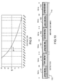
- the figure 9 shows, by way of example, the S / N ratio as a function of the distance, at the output of an FFT of 50 ms, on a fluctuating target of 1 m 2 according to the model SWERLING 1, this S / B ratio being represented by a curve 91.
- the cumulative detection probability is calculated with this hypothesis of average time.
- the frequency agility is stopped during the transmission of these four FFT sequences of 200 ms in total so that the target remains in the same configuration of fluctuation of SER that during its initial detection.
- a "detection" threshold is set, not to guarantee a certain false alarm rate, but so that the validated differential phase measurements are not tainted with prohibitive errors that could prevent the lifting of distance ambiguity as explained below.
- the track remains "internal" to the radar and is not communicated to the navigation system.
- the event counter is incremented by 1.
- the track is dropped. It is possible, in a security principle, to transmit to the navigation system a pre-alert.
- the modulo term is 3000 m.
- the SNR of the three non-detection cycles is set to zero.
- four estimators are open, with the four distance assumptions. It is possible, in a safety principle, to transmit to the navigation system a pre-alert for the track corresponding to the shortest distance, dressed with an indicator specifying the risk of ambiguity in distance. If, during the next scan cycle, the same case occurs, the event counter is incremented by a value ⁇ 1. The track is aborted when a certain threshold is exceeded.
- the detection in the standby phase directly provides an estimate of the angle ⁇ deduced from the mono-pulse deviation, for example as indicated by the relation (16).
- each equation is associated with a quality criterion "Q" between a minimum value and a maximum value.
- Q quality criterion
- a minimum value criterion is an unusable measure.
- a maximum value is a very good measure.
- This quality index "Q" may be a function of various parameters, for example: the S / N ratio, two measurements made using, in particular, two ⁇ F of opposite signs.
- the function " f " is a function of linearization of the measurement of deviometry, that is to say that it makes it possible to provide the estimate of the angle ⁇ without bias from the measurement of deviometry ⁇ of the relation (16) which is a monotonic but non-linear function of the angle ⁇ .
- the quality indices "Qa to Qd" are tested with respect to a threshold and only the equations corresponding to an index greater than the threshold are retained.
- this gap in minimum distance is tested with respect to a rejection threshold, a function of the quality indices. If this difference is less than the rejection threshold, the distance measure is declared valid and the integers of modulo "k" are deduced from the valid equations.
- the optimal value set of ⁇ F is to be determined by optimization techniques.
- the value set of ⁇ F should allow an ambiguity-free, rank-free ambiguity, regardless of the distance of the target in the range domain being processed, with the minimum S / N ratio; that is with the maximum of noise on each phase measurement. Measurement accuracy can also be taken into account when the S / N ratio is higher.
- a function of cost is to be defined and the set of ⁇ F which minimizes this function of cost is determined according to known mathematical methods.
- R Z at Quality index Qa X + ⁇ b .
- R Z b Qb quality index X + ⁇ vs .
- R Z vs Qc quality index X + ⁇ d .
- R Z d Qd quality index
- phase measurement has an error close to: ⁇ ⁇ ⁇ 1 2.
- the waveform may be slightly modified with respect to the shape presented in FIG. figure 10 .
- the established tracking corresponds to the maintenance case of the tracks in progress, except initialization of the tracks and off-stand alone.
- the standby sequence 100 is therefore followed in this case by a prosecution maintenance sequence.
- the modification consists in blocking the frequency of the carrier at a frequency different from that of the carrier of the preceding standby sequence in the prosecution maintenance sequence, instead of blocking it at the carrier frequency of the carrier. preceding sleep sequence.
- the correlation windows in angle and VRR are not centered around the planned point because the collision avoidance criterion makes it possible to predict the direction of the evolution, in particular, if one is not not in the event of an exact collision, the VRR can only go down.
- the method of resetting / filtering measurements / estimation can be any known method: Kalman filters, non-adaptive filters with deterministic gain coefficients, filters called " ⁇ , ⁇ " for example.
- This second waveform is limited in the instrumental domain, for example at 2000 meters in distance. This distance corresponds, as in the case of a fast target, to 20 seconds notice.
- the second waveform does not need to be as sensitive as the first one.
- the ratio of distances, 9200/2000, leads to a sensitivity difference of 26.5 dB, which is important.
- the average transmission power can be reduced by about 200 times.
- the radar principle associated with this second waveform is the same as that used for the first waveform.
- the coloring system of the space on transmission and the FFC on reception are retained. It is simply necessary to use a pulse cutter that is unnecessary in the case of continuous waveforms.
- the migration distance during the Doppler processing time is 5 meters .
- a distance resolution of 10 to 15 meters makes it possible to respect the criterion of no distance migration.
- the distance resolution is fixed at 15 meters, which corresponds to a transmitted band of 10 MHz and a temporal resolution of 100 ns.
- the same elementary pattern is used as for the first waveform, that is to say coherent durations close to 50 milliseconds grouped in pairs of duration of 100 milliseconds. .
- FR the recurrence frequency
- FR 13.2 kHz or PRI ⁇ 75 ⁇ s
- PRI being the period of recurrence.
- the unambiguous target distance condition results in PRI> 13.3 ⁇ s.
- the possible range of PRI is therefore [13.3; 75 ⁇ s].
- This solution uses the principle used for the first waveform, in particular the case described in figure 6b .
- is greater than or equal to 13.2 kHz (maximum Doppler band of ground clutter for a carrier at 100 m / s, ie spread of clutter over a band equivalent to 2Vp 200 m / s).
- FIG. 11a An example of a very simple waveform that satisfies all these criteria is illustrated by the Figures 11a and 11b , the figure 11a presenting the waveform for the first transmission subnetwork 23 and the figure 11b presenting the waveform for the second transmission subnetwork 24.
- the repetition frequency is 18 ⁇ s and the pulse width is 0.1 ⁇ s.
- the waveform of the figure 11a the frequency of the first pulse represented 111 is at the frequency F 11 , the second pulse 112 is at the frequency F 12 , then a new cycle starts again with a pulse 113 to F 11 and a pulse to F 12 not shown.
- the frequency of the first pulse represented 114 is at the frequency F 21
- the second pulse 115 is at the frequency F 22
- a new cycle, or elementary pattern starts again with a pulse 116 to F 21 and a pulse to F 22 not shown.
- the pulses of the two waveforms are synchronous, thus the pulse 111 to F 11 transmitted by the first sub-network 23 is synchronous with the pulse 114 to F 21 transmitted by the second subarray 24.
- F 11 F X + ⁇ ⁇ F / 2
- F 12 F Y + ⁇ ⁇ F / 2
- F 21 F X - ⁇ ⁇ F / 2
- F 22 F Y - ⁇ ⁇ F / 2
- the FFT pair block block FFT pair PRI will be slightly varied (ie 100 ms in 100 ms). Strictly speaking, we do not do ambiguity, but an ambiguous echo will not have an apparently coherent motion of a target in a collision course. As a result, a prosecution can not be established.
- the central frequencies Fx and Fy will be chosen so that all the distinct frequencies among the set of 4 preceding frequencies correspond to orthogonal pulses. If Fy > Fx and ⁇ F > 0 , this amounts to obtaining the orthogonality on the signals at F x + ⁇ F / 2 and F Y - ⁇ F l 2; this in order to limit the phenomena of aliasing ambiguous echoes.
- each cycle comprises for example four frequencies instead of two as in the case of the previous solution illustrated by the Figures 11a and 11b .
- a cycle transmitted by the first transmission subnetwork 23 comprises, for example, four successive pulses respectively at F 11 , F 12 , F 13 , F 14 .
- a cycle emitted by the second sub-array 24 comprises, for example, four successive pulses respectively at F 21 , F 22 , F 23 , F 24 .
- F 11 F X + ⁇ ⁇ F / 2
- F 12 F Y + ⁇ ⁇ F / 2
- F 21 F X - ⁇ ⁇ F / 2
- F 22 F Y - ⁇ ⁇ F / 2
- F 13 F X - ⁇ ⁇ F / 2
- F 14 F Y - ⁇ ⁇ F / 2
- F 23 F X + ⁇ ⁇ F / 2
- F 24 F Y + ⁇ ⁇ F / 2
- Another possible solution consists in sending the signal sequentially on the two sub-networks 23, 24 of the transmission network 11, 111, 112, 113.
- the gap between the emission of the pulse transmitted at the frequency F1 on the first sub-network 23 and the emission of the pulse at the frequency F2 on the second sub-network 24 must be sufficient to allow the desired range coverage, 2000 meters for example.
- This solution induces a coupling which is this time between the Doppler and the angle (distance).
- the repetition period of the code should be such that the Doppler band of the echoes to be processed is unambiguous.
- this orthogonality is sought at the level of the pulses, unlike the previous solutions.
- the first condition ensures the separation of channels, the second makes it possible to obtain an impulse response in satisfactory distance and the third makes it possible to overcome the Distance-Angle coupling.
- PN Pseudo-Noise
- the two orthogonal codes consist of a Barker code and the same Barker code returned in time.
- a subsidiary interest in the use of such codes is that they can also be used as pulse compression codes.
Landscapes
- Engineering & Computer Science (AREA)
- Radar, Positioning & Navigation (AREA)
- Remote Sensing (AREA)
- Physics & Mathematics (AREA)
- Computer Networks & Wireless Communication (AREA)
- General Physics & Mathematics (AREA)
- Aviation & Aerospace Engineering (AREA)
- Electromagnetism (AREA)
- Radar Systems Or Details Thereof (AREA)
Claims (19)
- Luftfahrzeug-Radarvorrichtung mit einem gegebenen Erfassungswinkel in Elevation und Azimut, umfassend ein Sendesystem (21), ein Empfangssystem (22) und Verarbeitungsmittel, die Messungen zum Erkennen und Orten von Zielen durchführen, wobei das Sendesystem Folgendes umfasst:- eine Sendeantenne bestehend aus P linearen Gruppen (111, 112, 113) von Strahlungselementen (2), die einen Sendestrahl fokussieren, wobei die Gruppen parallel zueinander sind;- wenigstens zwei Wellenfoimgeneratoren (25, 26);- Mittel zum Verstärken der von dem oder den Wellenformgenerator(en) (25, 26) erzeugten Sendesignale;- Mittel zum Steuern der von dem oder den Wellenformgenerator(en) (25, 26) erzeugten Sendesignale, wobei die Mittel jedes der Strahlungselemente (2) mit einem Sendestrahl versorgen;wobei die Strahlungselemente gesteuert werden zum:gleichzeitigen Erzeugen einer elektronischen Ablenkung des Sendestrahls in der Elevation und einer farbigen Sendung in der Elevation, wobei der erste Wellenformgenerator (25) ein Signal mit einer ersten Frequenz F1 liefert und der zweite Wellenformgenerator (26) ein Signal mit einer zweiten Frequenz F2 liefert, wobei jede Sendegruppe (111, 112, 113) in zwei Untergruppen (23, 24) unterteilt ist, wobei die Strahlungselemente (2) der ersten Untergruppe (23) mit dem Signal auf der ersten Frequenz F1 gespeist werden und die Strahlungselemente (2) der zweiten Untergruppe (24) mit dem Signal auf der zweiten Frequenz F2 gespeist werden, wobei die farbige Sendung durch Senden auf der ersten Untergruppe (23) mit der ersten Frequenz F1 und durch Senden auf der zweiten Untergruppe (24) mit der zweiten Frequenz F2 erhalten wird, wobei diese Radarvorrichtung dadurch gekennzeichnet ist, dass:das Empfangssystem (22) eine lineare Gruppe (12) von Strahlungselementen umfasst, die in einer orthogonalen Richtung mit Bezug auf die linearen Gruppen (11, 111, 112, 113) des Sendesystems orientiert ist, wobei die Verarbeitungsmittel (14) des Empfangs systems (22), in der Elevationsebene, eine Berechnung eines Summenkanals (Σ) und eines Differenzkanals (Δ) gemäß der Monopuls-Technik auf der Basis der Signale durchführen, die einerseits auf der ersten Frequenz F1 und andererseits auf der zweiten Frequenz F2 empfangen werden.
- Radarvorrichtung nach Anspruch 1, dadurch gekennzeichnet, dass die Steuermittel:- die Sendesignale so steuern, dass jede lineare Gruppe einen Sendestrahl in einer eigenen Richtung erzeugt, wobei der Satz von erzeugten Sendestrahlen in der Elevation winkelmäßig versetzt ist;- Schalter (27, 28) zum Umschalten der Sendesignale nacheinander zu jeder der P linearen Gruppen (111, 112, 113) umfassen;wobei die elektronische Ablenkung bei Sendung durch Umschalten der Versorgung mit Signalen von P Gruppen erhalten wird, deren Sendestrahlen in P getrennten Richtungen orientiert sind.
- Radarvorrichtung nach einem der vorherigen Ansprüche, dadurch gekennzeichnet, dass das Empfangssystem (22) Verarbeitungsmittel (14) umfasst, die einen Empfangsstrahl durch Strahlbildung durch Berechnung (73) in Azimut erzeugen.
- Radarvorrichtung nach einem der vorherigen Ansprüche, dadurch gekennzeichnet, dass sie die Erkennung und Ortung eines Ziels (I, 51) in wenigstens zwei Schritten bewirkt:- in einem ersten Schritt erkennt das Radar ein eventuelles Ziel mit einer maximalen Erkennungsempfindlichkeit und misst mindestens die Annäherungsgeschwindigkeit des Ziels an das Radar;- in einem zweiten Schritt führt das Radar, falls ein Ziel erkannt wird, eine Messung der Richtung (Ψ) und des Abstands (R) des Ziels durch.
- Radarvorrichtung nach einem der vorherigen Ansprüche, dadurch gekennzeichnet, dass die Erkennung eines Ziels eine Spektralanalyse mit sehr hoher Auflösung, gefolgt von einer nicht-kohärenten Integration langer Dauer nutzt, wobei diese beiden Charakteristiken an Ziele auf Kollisionskurs angepasst sind.
- Radarvorrichtung nach einem der vorherigen Ansprüche, dadurch gekennzeichnet, dass sie zwei Wellenformen benutzt, wobei ein Wellengenerator (25, 26) zwei Wellenformen liefert, wobei eine erste Wellenform (81, 82, 101, 102, 103, 104) an die schnellen Ziele angepasst ist, die in Doppler-Frequenz oder Abstand von thermischem Rauschen geortet werden, wobei die zweite Wellenform mit reduzierter Reichweite an die langsamen Ziele angepasst ist, die am Grund von Bodenecho erkennbar sind.
- Radarvorrichtung nach Anspruch 6, dadurch gekennzeichnet, dass sich die farbige Sendung der ersten Wellenform aus der Sendung von wenigstens zwei kontinuierlichen Wellen (65, 66) auf den Frequenzen F1 und F2 zusammensetzt, um k/T frequenzverschoben, wobei T die Doppler-Integrationszeit ist und k eine relative ganze Zahl von ungleich null ist.
- Radarvorrichtung nach Anspruch 7, dadurch gekennzeichnet, dass die Ambiguität von Winkel- und Abstandsmesswerten, die sich aus der Verwendung der ersten Wellenform mit Sendungsfärbung ergibt, aufgehoben wird, indem sinusförmige Wellen gesendet werden, die um mehrere Frequenzabweichungen voneinander beabstandet sind.
- Radarvorrichtung nach einem der Ansprüche 6 bis 8, dadurch gekennzeichnet, dass für die erste Wellenform Frequenzabweichungen (ΔF) zwischen Sendegruppen von entgegengesetzten Vorzeichen benutzt werden.
- Radarvorrichtung nach Anspruch 9, dadurch gekennzeichnet, dass die Aufhebung von Ambiguität der Winkel- und Abstandsmesswerte für die erste Wellenform zunächst unter Aufhebung des Ambiguitätsrangs an dem Abstandsmesswert mittels der mehreren Frequenzabweichungen erfolgt.
- Radarvorrichtung nach einem der Ansprüche 6 bis 10, dadurch gekennzeichnet, dass die zweite Wellenform (111, 112, 113, 114, 115, 116) eine pulsierte sinusförmige Welle ist.
- Radarvorrichtung nach Anspruch 11, dadurch gekennzeichnet, dass sich die farbige Sendung der zweiten Wellenform aus der Sendung von wenigstens zwei pulsierten sinusförmigen Wellen mit Trägerfrequenz F1 und F2 zusammensetzt, um k/T frequenzverschoben, wobei T die Doppler-Integrationszeit ist und k eine relative ganze Zahl von ungleich null ist.
- Radarvorrichtung nach Anspruch 11, dadurch gekennzeichnet, dass sich die farbige Sendung der zweiten Wellenform aus der Sendung von wenigstens zwei pulsierten sinusförmigen Trägerwellen zusammensetzt, um FR/q frequenzverschoben, wobei FR die Wiederholfrequenz von Impulsen ist und q eine positive ganze Zahl von ungleich null ist.
- Radarvorrichtung nach Anspruch 11, dadurch gekennzeichnet, dass sich die farbige Sendung der zweiten Wellenform aus der Sendung von wenigstens zwei pulsierten sinusförmigen Trägerwellen zusammensetzt, frequenzverschoben um die zweifache Abweichung der Doppler-Frequenz des Bodenechos.
- Radarvorrichtung nach Anspruch 11, dadurch gekennzeichnet, dass sich die farbige Sendung der zweiten Wellenform aus der Sendung von wenigstens zwei pulsierten sinusförmigen Trägerwellen zusammensetzt, frequenzverschoben um das Zweifache der maximalen Doppler-Frequenz des Bodens in der Trägerluftfahrzeugachse der Radarvorrichtung.
- Radarvorrichtung nach Anspruch 11, dadurch gekennzeichnet, dass, da die Empfangs signale in der Frequenzdomäne durch eine schnelle FFT-Fourier-Transformation transponiert werden, nutzt die farbige Sendung der zweiten Wellenform die Sendung von wenigstens zwei pulsierten sinusförmigen Trägerwellen, um eine Abweichung ΔF frequenzverschoben, wobei das Vorzeichen dieser Abweichung von einer Sequenz der schnellen Fourier, FFT-Transformation auf die Folgende geschaltet wird.
- Radarvorrichtung nach Anspruch 11, dadurch gekennzeichnet, dass, da die Empfangs signale in der Frequenzdomäne durch eine schnelle FFT-Fourier-Transformation transponiert werden, nutzt die farbige Sendung der zweiten Wellenform die Sendung von wenigstens zwei pulsierten sinusförmigen Trägerwellen, um eine Abweichung ΔF frequenzverschoben, wobei der Absolutwert dieser Abweichung von N FFT-Sequenzen auf N FFT-Sequenzen geschaltet werden.
- Radarvorrichtung nach Anspruch 11, dadurch gekennzeichnet, dass sich die farbige Sendung der zweiten Wellenform aus der Sendung von wenigstens zwei pulsierten sinusförmigen Wellen zusammensetzt, moduliert durch die orthogonalen Phasencodes.
- Radarvorrichtung nach Anspruch 11, dadurch gekennzeichnet, dass sich die farbige Sendung der zweiten Wellenform aus der Sendung von wenigstens zwei pulsierten sinusförmigen Wellen zusammensetzt, moduliert durch identische Barker-Codes, aber zeitlich umgekehrt.
Applications Claiming Priority (1)
| Application Number | Priority Date | Filing Date | Title |
|---|---|---|---|
| FR0904394A FR2950148B1 (fr) | 2009-09-15 | 2009-09-15 | Radar aeroporte a large couverture angulaire, notamment pour la fonction de detection et d'evitement d'obstacle |
Publications (3)
| Publication Number | Publication Date |
|---|---|
| EP2296006A2 EP2296006A2 (de) | 2011-03-16 |
| EP2296006A3 EP2296006A3 (de) | 2011-05-11 |
| EP2296006B1 true EP2296006B1 (de) | 2015-11-11 |
Family
ID=42133789
Family Applications (1)
| Application Number | Title | Priority Date | Filing Date |
|---|---|---|---|
| EP10176415.7A Active EP2296006B1 (de) | 2009-09-15 | 2010-09-13 | Breitband-Flugzeugradarvorrichtung mit großem Erfassungswinkel, insbesondere für die Funktion der Kollisionsvermeidung |
Country Status (3)
| Country | Link |
|---|---|
| US (1) | US8299958B2 (de) |
| EP (1) | EP2296006B1 (de) |
| FR (1) | FR2950148B1 (de) |
Families Citing this family (36)
| Publication number | Priority date | Publication date | Assignee | Title |
|---|---|---|---|---|
| FR2950147B1 (fr) * | 2009-09-15 | 2012-07-13 | Thales Sa | Radar a agilite de faisceau, notamment pour la fonction de detection et d'evitement d'obstacles |
| FR2965362B1 (fr) * | 2010-09-28 | 2013-08-09 | Thales Sa | Radar a grande couverture angulaire, notamment pour la fonction d'evitement d'obstacle a bord d'aeronefs autopilotes |
| FR2970085A1 (fr) * | 2010-12-30 | 2012-07-06 | Thales Sa | Procede d'extension de la portee instrumentee d'un radar |
| US8570210B1 (en) * | 2011-06-21 | 2013-10-29 | Lockheed Martin Corporation | Aircraft MIMO radar |
| DE102011083756A1 (de) * | 2011-09-29 | 2013-04-04 | Siemens Ag | Radar-Vorrichtung und Verfahren zum Erzeugen einer Gruppencharakteristik eines Radars |
| FR2987683B1 (fr) * | 2012-03-02 | 2016-11-11 | Thales Sa | Radar a faible probabilite d'interception |
| US9019148B1 (en) * | 2012-04-24 | 2015-04-28 | Sandia Corporation | Remote sensing using MIMO systems |
| JP6175863B2 (ja) * | 2013-03-29 | 2017-08-09 | 富士通株式会社 | レーダ装置及びプログラム |
| US9014914B2 (en) * | 2013-04-10 | 2015-04-21 | Here Global B.V. | Method and apparatus for establishing a communication session between parked vehicles to determine a suitable parking situation |
| FR3008800B1 (fr) * | 2013-07-19 | 2015-07-17 | Thales Sa | Dispositif de detection de signaux electromagnetiques |
| US9541639B2 (en) | 2014-03-05 | 2017-01-10 | Delphi Technologies, Inc. | MIMO antenna with elevation detection |
| US9568600B2 (en) * | 2014-03-05 | 2017-02-14 | Delphi Technologies, Inc. | MIMO antenna with elevation detection |
| US20150285904A1 (en) * | 2014-04-04 | 2015-10-08 | Texas Instruments Incorporated | Antenna configuration for parking assist radar |
| US10061018B1 (en) * | 2015-02-19 | 2018-08-28 | Zain Naboulsi | System for identifying drones |
| US10505643B2 (en) * | 2015-03-26 | 2019-12-10 | Lg Electronics Inc. | Method and device for estimating doppler frequency by using beam scanning process in wireless communication system |
| EP3156817B8 (de) * | 2015-10-12 | 2019-01-09 | Aptiv Technologies Limited | Mimo-radarantenne zur höhenwinkeldetektion |
| FR3056762B1 (fr) * | 2016-09-29 | 2018-09-07 | Thales | Procede de modulation d'une onde hyperfrequence, systeme d'emission mettant en oeuvre ce procede et radar comportant un tel systeme |
| US10705202B2 (en) * | 2017-01-19 | 2020-07-07 | GM Global Technology Operations LLC | Iterative approach to achieve angular ambiguity resolution |
| CN108957481A (zh) * | 2017-05-22 | 2018-12-07 | 深圳市道通智能航空技术有限公司 | 一种障碍检测方法、装置以及无人飞行器 |
| US11092686B2 (en) * | 2018-09-19 | 2021-08-17 | Steradian Semiconductors Private Limited | Method, apparatus and device for doppler compensation in a time switched MIMO radar system |
| US11262434B2 (en) * | 2019-04-01 | 2022-03-01 | GM Global Technology Operations LLC | Antenna array design and processing to eliminate false detections in a radar system |
| DE102020107804A1 (de) * | 2019-04-26 | 2020-10-29 | Infineon Technologies Ag | Radarvorrichtung und Verfahren zum Detektieren von Radarzielen |
| US11181614B2 (en) * | 2019-06-06 | 2021-11-23 | GM Global Technology Operations LLC | Antenna array tilt and processing to eliminate false detections in a radar system |
| WO2021019858A1 (ja) * | 2019-08-01 | 2021-02-04 | 古野電気株式会社 | 物標検出装置および物標検出方法 |
| WO2021060695A1 (ko) * | 2019-09-26 | 2021-04-01 | 삼성전자 주식회사 | 물체 검출 방법 및 항법 시스템 |
| US11301603B2 (en) * | 2020-01-21 | 2022-04-12 | Aptiv Technologies Limited | High-fidelity radar simulator |
| FR3116127B1 (fr) * | 2020-11-12 | 2022-11-11 | Thales Sa | Système radar d'imagerie à entrées et sorties multiples de type MIMO. |
| CN112731374A (zh) * | 2020-12-15 | 2021-04-30 | 四川九洲空管科技有限责任公司 | 一种二次雷达自适应航迹滤波方法 |
| JP7813244B2 (ja) | 2020-12-23 | 2026-02-12 | 古野電気株式会社 | 物標検出装置および物標検出方法 |
| FR3119027B1 (fr) * | 2021-01-19 | 2022-12-30 | Thales Sa | Radar à antenne active à couverture angulaire élargie |
| US12032054B2 (en) * | 2021-09-21 | 2024-07-09 | GM Global Technology Operations LLC | Multi-stage angle of arrival estimate in vehicle radar system |
| CN115052295B (zh) * | 2022-05-12 | 2023-10-24 | 电子科技大学 | 一种实时的相控阵雷达组网系统的资源管理方法 |
| CN115656944B (zh) * | 2022-10-21 | 2025-05-16 | 哈尔滨工程大学 | 基于mimo雷达的舰船图像电磁散射特征闪烁的精确校正方法 |
| FR3148302B1 (fr) * | 2023-04-27 | 2025-05-09 | Thales Sa | Système de détection comprenant une antenne réseau à commande de phase et procédé de détection associé |
| KR20240171830A (ko) * | 2023-05-31 | 2024-12-09 | 한국과학기술원 | 2차원 위상하위배열 mimo 레이다 |
| CN118655564B (zh) * | 2024-06-12 | 2026-05-12 | 北京理工大学 | 一种基于无人机载双通道穿墙雷达干涉相位的建筑内部动目标重定位方法 |
Family Cites Families (7)
| Publication number | Priority date | Publication date | Assignee | Title |
|---|---|---|---|---|
| JPH10507936A (ja) * | 1994-08-05 | 1998-08-04 | アキュソン コーポレイション | 送信ビーム生成器システムのための方法及び装置 |
| FR2882855B1 (fr) * | 2005-03-01 | 2007-05-18 | Thales Sa | Module actif integre a une antenne a balayage electronique et radar comportant une telle antenne, notamment applique a la meteorologie |
| US7205928B1 (en) * | 2006-05-31 | 2007-04-17 | Honeywell International Inc. | Automatic weather radar system and method |
| FR2949867B1 (fr) * | 2009-09-04 | 2012-04-27 | Thales Sa | Dispositif radar aeroporte multifonction a large bande de large couverture angulaire permettant la detection et le pistage, notamment pour une fonction de detection et evitement |
| FR2950147B1 (fr) * | 2009-09-15 | 2012-07-13 | Thales Sa | Radar a agilite de faisceau, notamment pour la fonction de detection et d'evitement d'obstacles |
| FR2951278B1 (fr) * | 2009-10-12 | 2011-10-21 | Thales Sa | Radar a grande precision angulaire, notamment pour la fonction de detection et d'evitement d'obstacle |
| FR2954516B1 (fr) * | 2009-12-18 | 2012-09-21 | Thales Sa | Procede de detection radar, notamment pour des radars aeroportes mettant en oeuvre une fonction de detection et d'evitement d'obstacles |
-
2009
- 2009-09-15 FR FR0904394A patent/FR2950148B1/fr not_active Expired - Fee Related
-
2010
- 2010-09-13 EP EP10176415.7A patent/EP2296006B1/de active Active
- 2010-09-14 US US12/881,230 patent/US8299958B2/en active Active
Non-Patent Citations (1)
| Title |
|---|
| LE CHAVALIER F: "Space-Time Transmission and Coding for Airborne Radars", LEIDA-KEXUE-YU-JISHU = RADAR SCIENCE AND TECHNOLOGY,, vol. 6, no. 6, 1 December 2008 (2008-12-01), pages 411 - 421, XP009130674, ISSN: 1672-2337 * |
Also Published As
| Publication number | Publication date |
|---|---|
| US20110140952A1 (en) | 2011-06-16 |
| EP2296006A2 (de) | 2011-03-16 |
| FR2950148A1 (fr) | 2011-03-18 |
| FR2950148B1 (fr) | 2012-06-15 |
| US8299958B2 (en) | 2012-10-30 |
| EP2296006A3 (de) | 2011-05-11 |
Similar Documents
| Publication | Publication Date | Title |
|---|---|---|
| EP2296006A2 (de) | Breitband-Flugzeugradarvorrichtung mit großem Erfassungswinkel, insbesondere für die Funktion der Kollisionsvermeidung | |
| EP2122388B1 (de) | Einrichtung und verfahren zum lokalisieren einer mobilen einrichtung, die sich einer elektromagnetische wellen reflektierenden oberfläche nähert | |
| EP2296007B1 (de) | Radar mit Strahlagilität für Erkennung und Vermeidung von Hindernissen | |
| EP3588137B1 (de) | Verfahren zur detektion und lokalisation falscher ads-b-ziele, und system mit sekundärradaren, das dieses verfahren umsetzt | |
| US9829568B2 (en) | Radar using hermetic transforms | |
| EP2287633B1 (de) | Radar zur Erkennung von Luftzielen, der als Ausrüstung eines Luftfahrzeugs dient, insbesondere zur Hindernisumfliegung | |
| EP2831615B1 (de) | Vorrichtung für aktive und passive elektromagnetische detektion mit geringer wahrscheinlichkeit von unterbrechungen | |
| EP3973321B1 (de) | Mehrfachzeitskalen-doppler-verfahren und assoziierte systeme und verfahren | |
| EP4246176A2 (de) | Verfahren und system zur steuerung eines autonomen fahrzeugs unter verwendung von optischen dopplersensoren mit kohärentem bereich | |
| EP4165435B1 (de) | Bistatisches oder multistatisches radarsystem zur luftüberwachung mit räumlicher beleuchtung | |
| WO2021219398A1 (fr) | Procédé d'imagerie radar, et radar mettant en œuvre un tel procédé | |
| FR2998975A1 (fr) | Procede de filtrage, dans un signal radar, des ambiguites distance par codage d'impulsions et traitement multi-voies | |
| EP4330722B1 (de) | Radarsystem und zugehöriges verfahren zur optimierung der beseitigung von radarstörungen | |
| EP4671824A1 (de) | Verfahren zum betrieb eines radars nach einem apertursynthese- und einem zweiten betriebsmodus mit zufallsphasen und radar dafür | |
| FR3168017A1 (fr) | Procédé de fonctionnement d'un radar suivant un mode d'imagerie à synthèse d'ouverture et un deuxième mode de fonctionnement utilisant une alternance de polarisation et radar associé | |
| FR3140177A1 (fr) | Procédé et dispositif de détection d’obstacles proches par Radar Passif Multistatique GNSS pour plateformes mobiles | |
| FR3168018A1 (fr) | Procédé de fonctionnement d'un radar suivant un mode d'imagerie à synthèse d'ouverture et un deuxième mose de fonctionnement utilisant des phases aléatoires et radar associé | |
| FR3168015A1 (fr) | Procédé de fonctionnement d'un radar suivant un mode d'imagerie à synthèse d'ouverture et un deuxième mode de fonctionnement utilisant des pentes de chirp et radar associé | |
| FR3168020A1 (fr) | Procédé de fonctionnement d'un radar de détection suivant au moins au mode de fonctionnement d'observation utilisant une alternance de polarisations et radar de détection associé | |
| FR3168013A1 (fr) | Procédé de fonctionnement d'un radar de détection suivant au moins au mode de fonctionnement d'observation utilisant des pentes de chirp et radar de détection associé | |
| Pham | Around-the-Corner radar: localization and tracking of a non-line-of-sight target in the presence of ambiguities | |
| FR3168016A1 (fr) | Procédé de fonctionnement d'un radar de détection suivant au moins au mode de fonctionnement d'observation utilisant des phases aléatoires et radar de détection associé | |
| FR3168019A1 (fr) | Procédé d'observation d'un environnement et radar de détection associé | |
| EP4671823A1 (de) | Verfahren zum betreiben eines sensorradars und sensorradar dafür | |
| EP4671807A1 (de) | Verfahren zum betreiben eines sensorradars und sensorradar dafür |
Legal Events
| Date | Code | Title | Description |
|---|---|---|---|
| PUAI | Public reference made under article 153(3) epc to a published international application that has entered the european phase |
Free format text: ORIGINAL CODE: 0009012 |
|
| AK | Designated contracting states |
Kind code of ref document: A2 Designated state(s): AL AT BE BG CH CY CZ DE DK EE ES FI FR GB GR HR HU IE IS IT LI LT LU LV MC MK MT NL NO PL PT RO SE SI SK SM TR |
|
| AX | Request for extension of the european patent |
Extension state: BA ME RS |
|
| PUAL | Search report despatched |
Free format text: ORIGINAL CODE: 0009013 |
|
| AK | Designated contracting states |
Kind code of ref document: A3 Designated state(s): AL AT BE BG CH CY CZ DE DK EE ES FI FR GB GR HR HU IE IS IT LI LT LU LV MC MK MT NL NO PL PT RO SE SI SK SM TR |
|
| AX | Request for extension of the european patent |
Extension state: BA ME RS |
|
| RIN1 | Information on inventor provided before grant (corrected) |
Inventor name: LE BIHAN, PATRICK Inventor name: NOUVEL, MYRIAM Inventor name: CORNIC, PASCAL Inventor name: KEMKEMIAN, STEPHANE |
|
| 17P | Request for examination filed |
Effective date: 20111110 |
|
| 17Q | First examination report despatched |
Effective date: 20111222 |
|
| GRAP | Despatch of communication of intention to grant a patent |
Free format text: ORIGINAL CODE: EPIDOSNIGR1 |
|
| INTG | Intention to grant announced |
Effective date: 20150715 |
|
| GRAS | Grant fee paid |
Free format text: ORIGINAL CODE: EPIDOSNIGR3 |
|
| GRAA | (expected) grant |
Free format text: ORIGINAL CODE: 0009210 |
|
| AK | Designated contracting states |
Kind code of ref document: B1 Designated state(s): AL AT BE BG CH CY CZ DE DK EE ES FI FR GB GR HR HU IE IS IT LI LT LU LV MC MK MT NL NO PL PT RO SE SI SK SM TR |
|
| REG | Reference to a national code |
Ref country code: GB Ref legal event code: FG4D Free format text: NOT ENGLISH |
|
| REG | Reference to a national code |
Ref country code: CH Ref legal event code: EP |
|
| REG | Reference to a national code |
Ref country code: IE Ref legal event code: FG4D Free format text: LANGUAGE OF EP DOCUMENT: FRENCH |
|
| REG | Reference to a national code |
Ref country code: AT Ref legal event code: REF Ref document number: 760728 Country of ref document: AT Kind code of ref document: T Effective date: 20151215 |
|
| REG | Reference to a national code |
Ref country code: DE Ref legal event code: R096 Ref document number: 602010028917 Country of ref document: DE |
|
| REG | Reference to a national code |
Ref country code: LT Ref legal event code: MG4D |
|
| REG | Reference to a national code |
Ref country code: NL Ref legal event code: MP Effective date: 20160211 |
|
| REG | Reference to a national code |
Ref country code: AT Ref legal event code: MK05 Ref document number: 760728 Country of ref document: AT Kind code of ref document: T Effective date: 20151111 |
|
| PG25 | Lapsed in a contracting state [announced via postgrant information from national office to epo] |
Ref country code: NO Free format text: LAPSE BECAUSE OF FAILURE TO SUBMIT A TRANSLATION OF THE DESCRIPTION OR TO PAY THE FEE WITHIN THE PRESCRIBED TIME-LIMIT Effective date: 20160211 Ref country code: LT Free format text: LAPSE BECAUSE OF FAILURE TO SUBMIT A TRANSLATION OF THE DESCRIPTION OR TO PAY THE FEE WITHIN THE PRESCRIBED TIME-LIMIT Effective date: 20151111 Ref country code: ES Free format text: LAPSE BECAUSE OF FAILURE TO SUBMIT A TRANSLATION OF THE DESCRIPTION OR TO PAY THE FEE WITHIN THE PRESCRIBED TIME-LIMIT Effective date: 20151111 Ref country code: HR Free format text: LAPSE BECAUSE OF FAILURE TO SUBMIT A TRANSLATION OF THE DESCRIPTION OR TO PAY THE FEE WITHIN THE PRESCRIBED TIME-LIMIT Effective date: 20151111 Ref country code: IS Free format text: LAPSE BECAUSE OF FAILURE TO SUBMIT A TRANSLATION OF THE DESCRIPTION OR TO PAY THE FEE WITHIN THE PRESCRIBED TIME-LIMIT Effective date: 20160311 Ref country code: NL Free format text: LAPSE BECAUSE OF FAILURE TO SUBMIT A TRANSLATION OF THE DESCRIPTION OR TO PAY THE FEE WITHIN THE PRESCRIBED TIME-LIMIT Effective date: 20151111 |
|
| PG25 | Lapsed in a contracting state [announced via postgrant information from national office to epo] |
Ref country code: GR Free format text: LAPSE BECAUSE OF FAILURE TO SUBMIT A TRANSLATION OF THE DESCRIPTION OR TO PAY THE FEE WITHIN THE PRESCRIBED TIME-LIMIT Effective date: 20160212 Ref country code: PL Free format text: LAPSE BECAUSE OF FAILURE TO SUBMIT A TRANSLATION OF THE DESCRIPTION OR TO PAY THE FEE WITHIN THE PRESCRIBED TIME-LIMIT Effective date: 20151111 Ref country code: SE Free format text: LAPSE BECAUSE OF FAILURE TO SUBMIT A TRANSLATION OF THE DESCRIPTION OR TO PAY THE FEE WITHIN THE PRESCRIBED TIME-LIMIT Effective date: 20151111 Ref country code: LV Free format text: LAPSE BECAUSE OF FAILURE TO SUBMIT A TRANSLATION OF THE DESCRIPTION OR TO PAY THE FEE WITHIN THE PRESCRIBED TIME-LIMIT Effective date: 20151111 Ref country code: PT Free format text: LAPSE BECAUSE OF FAILURE TO SUBMIT A TRANSLATION OF THE DESCRIPTION OR TO PAY THE FEE WITHIN THE PRESCRIBED TIME-LIMIT Effective date: 20160311 Ref country code: AT Free format text: LAPSE BECAUSE OF FAILURE TO SUBMIT A TRANSLATION OF THE DESCRIPTION OR TO PAY THE FEE WITHIN THE PRESCRIBED TIME-LIMIT Effective date: 20151111 Ref country code: FI Free format text: LAPSE BECAUSE OF FAILURE TO SUBMIT A TRANSLATION OF THE DESCRIPTION OR TO PAY THE FEE WITHIN THE PRESCRIBED TIME-LIMIT Effective date: 20151111 |
|
| PG25 | Lapsed in a contracting state [announced via postgrant information from national office to epo] |
Ref country code: CZ Free format text: LAPSE BECAUSE OF FAILURE TO SUBMIT A TRANSLATION OF THE DESCRIPTION OR TO PAY THE FEE WITHIN THE PRESCRIBED TIME-LIMIT Effective date: 20151111 |
|
| REG | Reference to a national code |
Ref country code: DE Ref legal event code: R097 Ref document number: 602010028917 Country of ref document: DE |
|
| REG | Reference to a national code |
Ref country code: FR Ref legal event code: PLFP Year of fee payment: 7 |
|
| PG25 | Lapsed in a contracting state [announced via postgrant information from national office to epo] |
Ref country code: SM Free format text: LAPSE BECAUSE OF FAILURE TO SUBMIT A TRANSLATION OF THE DESCRIPTION OR TO PAY THE FEE WITHIN THE PRESCRIBED TIME-LIMIT Effective date: 20151111 Ref country code: RO Free format text: LAPSE BECAUSE OF FAILURE TO SUBMIT A TRANSLATION OF THE DESCRIPTION OR TO PAY THE FEE WITHIN THE PRESCRIBED TIME-LIMIT Effective date: 20151111 Ref country code: EE Free format text: LAPSE BECAUSE OF FAILURE TO SUBMIT A TRANSLATION OF THE DESCRIPTION OR TO PAY THE FEE WITHIN THE PRESCRIBED TIME-LIMIT Effective date: 20151111 Ref country code: SK Free format text: LAPSE BECAUSE OF FAILURE TO SUBMIT A TRANSLATION OF THE DESCRIPTION OR TO PAY THE FEE WITHIN THE PRESCRIBED TIME-LIMIT Effective date: 20151111 Ref country code: DK Free format text: LAPSE BECAUSE OF FAILURE TO SUBMIT A TRANSLATION OF THE DESCRIPTION OR TO PAY THE FEE WITHIN THE PRESCRIBED TIME-LIMIT Effective date: 20151111 |
|
| PLBE | No opposition filed within time limit |
Free format text: ORIGINAL CODE: 0009261 |
|
| STAA | Information on the status of an ep patent application or granted ep patent |
Free format text: STATUS: NO OPPOSITION FILED WITHIN TIME LIMIT |
|
| 26N | No opposition filed |
Effective date: 20160812 |
|
| PG25 | Lapsed in a contracting state [announced via postgrant information from national office to epo] |
Ref country code: SI Free format text: LAPSE BECAUSE OF FAILURE TO SUBMIT A TRANSLATION OF THE DESCRIPTION OR TO PAY THE FEE WITHIN THE PRESCRIBED TIME-LIMIT Effective date: 20151111 |
|
| PG25 | Lapsed in a contracting state [announced via postgrant information from national office to epo] |
Ref country code: BE Free format text: LAPSE BECAUSE OF NON-PAYMENT OF DUE FEES Effective date: 20160930 |
|
| PG25 | Lapsed in a contracting state [announced via postgrant information from national office to epo] |
Ref country code: MC Free format text: LAPSE BECAUSE OF FAILURE TO SUBMIT A TRANSLATION OF THE DESCRIPTION OR TO PAY THE FEE WITHIN THE PRESCRIBED TIME-LIMIT Effective date: 20151111 |
|
| REG | Reference to a national code |
Ref country code: CH Ref legal event code: PL |
|
| REG | Reference to a national code |
Ref country code: IE Ref legal event code: MM4A |
|
| REG | Reference to a national code |
Ref country code: DE Ref legal event code: R082 Ref document number: 602010028917 Country of ref document: DE |
|
| PG25 | Lapsed in a contracting state [announced via postgrant information from national office to epo] |
Ref country code: IE Free format text: LAPSE BECAUSE OF NON-PAYMENT OF DUE FEES Effective date: 20160913 Ref country code: LI Free format text: LAPSE BECAUSE OF NON-PAYMENT OF DUE FEES Effective date: 20160930 Ref country code: CH Free format text: LAPSE BECAUSE OF NON-PAYMENT OF DUE FEES Effective date: 20160930 |
|
| REG | Reference to a national code |
Ref country code: FR Ref legal event code: PLFP Year of fee payment: 8 |
|
| PG25 | Lapsed in a contracting state [announced via postgrant information from national office to epo] |
Ref country code: LU Free format text: LAPSE BECAUSE OF NON-PAYMENT OF DUE FEES Effective date: 20160913 |
|
| REG | Reference to a national code |
Ref country code: BE Ref legal event code: MM Effective date: 20160930 |
|
| PG25 | Lapsed in a contracting state [announced via postgrant information from national office to epo] |
Ref country code: CY Free format text: LAPSE BECAUSE OF FAILURE TO SUBMIT A TRANSLATION OF THE DESCRIPTION OR TO PAY THE FEE WITHIN THE PRESCRIBED TIME-LIMIT Effective date: 20151111 Ref country code: HU Free format text: LAPSE BECAUSE OF FAILURE TO SUBMIT A TRANSLATION OF THE DESCRIPTION OR TO PAY THE FEE WITHIN THE PRESCRIBED TIME-LIMIT; INVALID AB INITIO Effective date: 20100913 |
|
| PG25 | Lapsed in a contracting state [announced via postgrant information from national office to epo] |
Ref country code: MT Free format text: LAPSE BECAUSE OF FAILURE TO SUBMIT A TRANSLATION OF THE DESCRIPTION OR TO PAY THE FEE WITHIN THE PRESCRIBED TIME-LIMIT Effective date: 20151111 Ref country code: TR Free format text: LAPSE BECAUSE OF FAILURE TO SUBMIT A TRANSLATION OF THE DESCRIPTION OR TO PAY THE FEE WITHIN THE PRESCRIBED TIME-LIMIT Effective date: 20151111 Ref country code: MK Free format text: LAPSE BECAUSE OF FAILURE TO SUBMIT A TRANSLATION OF THE DESCRIPTION OR TO PAY THE FEE WITHIN THE PRESCRIBED TIME-LIMIT Effective date: 20151111 |
|
| PG25 | Lapsed in a contracting state [announced via postgrant information from national office to epo] |
Ref country code: BG Free format text: LAPSE BECAUSE OF FAILURE TO SUBMIT A TRANSLATION OF THE DESCRIPTION OR TO PAY THE FEE WITHIN THE PRESCRIBED TIME-LIMIT Effective date: 20151111 |
|
| REG | Reference to a national code |
Ref country code: FR Ref legal event code: PLFP Year of fee payment: 9 |
|
| PG25 | Lapsed in a contracting state [announced via postgrant information from national office to epo] |
Ref country code: AL Free format text: LAPSE BECAUSE OF FAILURE TO SUBMIT A TRANSLATION OF THE DESCRIPTION OR TO PAY THE FEE WITHIN THE PRESCRIBED TIME-LIMIT Effective date: 20151111 |
|
| P01 | Opt-out of the competence of the unified patent court (upc) registered |
Effective date: 20230427 |
|
| PGFP | Annual fee paid to national office [announced via postgrant information from national office to epo] |
Ref country code: DE Payment date: 20250819 Year of fee payment: 16 |
|
| PGFP | Annual fee paid to national office [announced via postgrant information from national office to epo] |
Ref country code: IT Payment date: 20250827 Year of fee payment: 16 |
|
| PGFP | Annual fee paid to national office [announced via postgrant information from national office to epo] |
Ref country code: GB Payment date: 20250814 Year of fee payment: 16 |
|
| PGFP | Annual fee paid to national office [announced via postgrant information from national office to epo] |
Ref country code: FR Payment date: 20250821 Year of fee payment: 16 |