EP4330722B1 - Radarsystem und zugehöriges verfahren zur optimierung der beseitigung von radarstörungen - Google Patents
Radarsystem und zugehöriges verfahren zur optimierung der beseitigung von radarstörungen Download PDFInfo
- Publication number
- EP4330722B1 EP4330722B1 EP23709219.2A EP23709219A EP4330722B1 EP 4330722 B1 EP4330722 B1 EP 4330722B1 EP 23709219 A EP23709219 A EP 23709219A EP 4330722 B1 EP4330722 B1 EP 4330722B1
- Authority
- EP
- European Patent Office
- Prior art keywords
- signal
- filtering
- doppler
- radar system
- frequency channel
- Prior art date
- Legal status (The legal status is an assumption and is not a legal conclusion. Google has not performed a legal analysis and makes no representation as to the accuracy of the status listed.)
- Active
Links
Images




Classifications
-
- G—PHYSICS
- G01—MEASURING; TESTING
- G01S—RADIO DIRECTION-FINDING; RADIO NAVIGATION; DETERMINING DISTANCE OR VELOCITY BY USE OF RADIO WAVES; LOCATING OR PRESENCE-DETECTING BY USE OF THE REFLECTION OR RERADIATION OF RADIO WAVES; ANALOGOUS ARRANGEMENTS USING OTHER WAVES
- G01S13/00—Systems using the reflection or reradiation of radio waves, e.g. radar systems; Analogous systems using reflection or reradiation of waves whose nature or wavelength is irrelevant or unspecified
- G01S13/003—Bistatic radar systems; Multistatic radar systems
-
- G—PHYSICS
- G01—MEASURING; TESTING
- G01S—RADIO DIRECTION-FINDING; RADIO NAVIGATION; DETERMINING DISTANCE OR VELOCITY BY USE OF RADIO WAVES; LOCATING OR PRESENCE-DETECTING BY USE OF THE REFLECTION OR RERADIATION OF RADIO WAVES; ANALOGOUS ARRANGEMENTS USING OTHER WAVES
- G01S13/00—Systems using the reflection or reradiation of radio waves, e.g. radar systems; Analogous systems using reflection or reradiation of waves whose nature or wavelength is irrelevant or unspecified
- G01S13/02—Systems using reflection of radio waves, e.g. primary radar systems; Analogous systems
- G01S13/06—Systems determining position data of a target
-
- G—PHYSICS
- G01—MEASURING; TESTING
- G01S—RADIO DIRECTION-FINDING; RADIO NAVIGATION; DETERMINING DISTANCE OR VELOCITY BY USE OF RADIO WAVES; LOCATING OR PRESENCE-DETECTING BY USE OF THE REFLECTION OR RERADIATION OF RADIO WAVES; ANALOGOUS ARRANGEMENTS USING OTHER WAVES
- G01S13/00—Systems using the reflection or reradiation of radio waves, e.g. radar systems; Analogous systems using reflection or reradiation of waves whose nature or wavelength is irrelevant or unspecified
- G01S13/02—Systems using reflection of radio waves, e.g. primary radar systems; Analogous systems
- G01S13/06—Systems determining position data of a target
- G01S13/08—Systems for measuring distance only
- G01S13/10—Systems for measuring distance only using transmission of interrupted, pulse modulated waves
- G01S13/106—Systems for measuring distance only using transmission of interrupted, pulse modulated waves using transmission of pulses having some particular characteristics
-
- G—PHYSICS
- G01—MEASURING; TESTING
- G01S—RADIO DIRECTION-FINDING; RADIO NAVIGATION; DETERMINING DISTANCE OR VELOCITY BY USE OF RADIO WAVES; LOCATING OR PRESENCE-DETECTING BY USE OF THE REFLECTION OR RERADIATION OF RADIO WAVES; ANALOGOUS ARRANGEMENTS USING OTHER WAVES
- G01S13/00—Systems using the reflection or reradiation of radio waves, e.g. radar systems; Analogous systems using reflection or reradiation of waves whose nature or wavelength is irrelevant or unspecified
- G01S13/02—Systems using reflection of radio waves, e.g. primary radar systems; Analogous systems
- G01S13/06—Systems determining position data of a target
- G01S13/08—Systems for measuring distance only
- G01S13/10—Systems for measuring distance only using transmission of interrupted, pulse modulated waves
- G01S13/22—Systems for measuring distance only using transmission of interrupted, pulse modulated waves using irregular pulse repetition frequency
- G01S13/225—Systems for measuring distance only using transmission of interrupted, pulse modulated waves using irregular pulse repetition frequency with cyclic repetition of a non-uniform pulse sequence, e.g. staggered PRF
-
- G—PHYSICS
- G01—MEASURING; TESTING
- G01S—RADIO DIRECTION-FINDING; RADIO NAVIGATION; DETERMINING DISTANCE OR VELOCITY BY USE OF RADIO WAVES; LOCATING OR PRESENCE-DETECTING BY USE OF THE REFLECTION OR RERADIATION OF RADIO WAVES; ANALOGOUS ARRANGEMENTS USING OTHER WAVES
- G01S13/00—Systems using the reflection or reradiation of radio waves, e.g. radar systems; Analogous systems using reflection or reradiation of waves whose nature or wavelength is irrelevant or unspecified
- G01S13/02—Systems using reflection of radio waves, e.g. primary radar systems; Analogous systems
- G01S13/06—Systems determining position data of a target
- G01S13/08—Systems for measuring distance only
- G01S13/10—Systems for measuring distance only using transmission of interrupted, pulse modulated waves
- G01S13/26—Systems for measuring distance only using transmission of interrupted, pulse modulated waves wherein the transmitted pulses use a frequency- or phase-modulated carrier wave
-
- G—PHYSICS
- G01—MEASURING; TESTING
- G01S—RADIO DIRECTION-FINDING; RADIO NAVIGATION; DETERMINING DISTANCE OR VELOCITY BY USE OF RADIO WAVES; LOCATING OR PRESENCE-DETECTING BY USE OF THE REFLECTION OR RERADIATION OF RADIO WAVES; ANALOGOUS ARRANGEMENTS USING OTHER WAVES
- G01S13/00—Systems using the reflection or reradiation of radio waves, e.g. radar systems; Analogous systems using reflection or reradiation of waves whose nature or wavelength is irrelevant or unspecified
- G01S13/02—Systems using reflection of radio waves, e.g. primary radar systems; Analogous systems
- G01S13/06—Systems determining position data of a target
- G01S13/08—Systems for measuring distance only
- G01S13/10—Systems for measuring distance only using transmission of interrupted, pulse modulated waves
- G01S13/30—Systems for measuring distance only using transmission of interrupted, pulse modulated waves using more than one pulse per radar period
-
- G—PHYSICS
- G01—MEASURING; TESTING
- G01S—RADIO DIRECTION-FINDING; RADIO NAVIGATION; DETERMINING DISTANCE OR VELOCITY BY USE OF RADIO WAVES; LOCATING OR PRESENCE-DETECTING BY USE OF THE REFLECTION OR RERADIATION OF RADIO WAVES; ANALOGOUS ARRANGEMENTS USING OTHER WAVES
- G01S13/00—Systems using the reflection or reradiation of radio waves, e.g. radar systems; Analogous systems using reflection or reradiation of waves whose nature or wavelength is irrelevant or unspecified
- G01S13/02—Systems using reflection of radio waves, e.g. primary radar systems; Analogous systems
- G01S13/50—Systems of measurement based on relative movement of target
- G01S13/52—Discriminating between fixed and moving objects or between objects moving at different speeds
- G01S13/522—Discriminating between fixed and moving objects or between objects moving at different speeds using transmissions of interrupted pulse modulated waves
- G01S13/524—Discriminating between fixed and moving objects or between objects moving at different speeds using transmissions of interrupted pulse modulated waves based upon the phase or frequency shift resulting from movement of objects, with reference to the transmitted signals, e.g. coherent MTi
- G01S13/53—Discriminating between fixed and moving objects or between objects moving at different speeds using transmissions of interrupted pulse modulated waves based upon the phase or frequency shift resulting from movement of objects, with reference to the transmitted signals, e.g. coherent MTi performing filtering on a single spectral line and associated with one or more range gates with a phase detector or a frequency mixer to extract the Doppler information, e.g. pulse Doppler radar
-
- G—PHYSICS
- G01—MEASURING; TESTING
- G01S—RADIO DIRECTION-FINDING; RADIO NAVIGATION; DETERMINING DISTANCE OR VELOCITY BY USE OF RADIO WAVES; LOCATING OR PRESENCE-DETECTING BY USE OF THE REFLECTION OR RERADIATION OF RADIO WAVES; ANALOGOUS ARRANGEMENTS USING OTHER WAVES
- G01S13/00—Systems using the reflection or reradiation of radio waves, e.g. radar systems; Analogous systems using reflection or reradiation of waves whose nature or wavelength is irrelevant or unspecified
- G01S13/02—Systems using reflection of radio waves, e.g. primary radar systems; Analogous systems
- G01S13/50—Systems of measurement based on relative movement of target
- G01S13/58—Velocity or trajectory determination systems; Sense-of-movement determination systems
- G01S13/581—Velocity or trajectory determination systems; Sense-of-movement determination systems using transmission of interrupted pulse modulated waves and based upon the Doppler effect resulting from movement of targets
- G01S13/582—Velocity or trajectory determination systems; Sense-of-movement determination systems using transmission of interrupted pulse modulated waves and based upon the Doppler effect resulting from movement of targets adapted for simultaneous range and velocity measurements
-
- G—PHYSICS
- G01—MEASURING; TESTING
- G01S—RADIO DIRECTION-FINDING; RADIO NAVIGATION; DETERMINING DISTANCE OR VELOCITY BY USE OF RADIO WAVES; LOCATING OR PRESENCE-DETECTING BY USE OF THE REFLECTION OR RERADIATION OF RADIO WAVES; ANALOGOUS ARRANGEMENTS USING OTHER WAVES
- G01S13/00—Systems using the reflection or reradiation of radio waves, e.g. radar systems; Analogous systems using reflection or reradiation of waves whose nature or wavelength is irrelevant or unspecified
- G01S13/87—Combinations of radar systems, e.g. primary radar and secondary radar
- G01S13/878—Combination of several spaced transmitters or receivers of known location for determining the position of a transponder or a reflector
-
- G—PHYSICS
- G01—MEASURING; TESTING
- G01S—RADIO DIRECTION-FINDING; RADIO NAVIGATION; DETERMINING DISTANCE OR VELOCITY BY USE OF RADIO WAVES; LOCATING OR PRESENCE-DETECTING BY USE OF THE REFLECTION OR RERADIATION OF RADIO WAVES; ANALOGOUS ARRANGEMENTS USING OTHER WAVES
- G01S13/00—Systems using the reflection or reradiation of radio waves, e.g. radar systems; Analogous systems using reflection or reradiation of waves whose nature or wavelength is irrelevant or unspecified
- G01S13/88—Radar or analogous systems specially adapted for specific applications
- G01S13/91—Radar or analogous systems specially adapted for specific applications for traffic control
-
- G—PHYSICS
- G01—MEASURING; TESTING
- G01S—RADIO DIRECTION-FINDING; RADIO NAVIGATION; DETERMINING DISTANCE OR VELOCITY BY USE OF RADIO WAVES; LOCATING OR PRESENCE-DETECTING BY USE OF THE REFLECTION OR RERADIATION OF RADIO WAVES; ANALOGOUS ARRANGEMENTS USING OTHER WAVES
- G01S13/00—Systems using the reflection or reradiation of radio waves, e.g. radar systems; Analogous systems using reflection or reradiation of waves whose nature or wavelength is irrelevant or unspecified
- G01S13/88—Radar or analogous systems specially adapted for specific applications
- G01S13/95—Radar or analogous systems specially adapted for specific applications for meteorological use
- G01S13/955—Radar or analogous systems specially adapted for specific applications for meteorological use mounted on satellite
-
- G—PHYSICS
- G01—MEASURING; TESTING
- G01S—RADIO DIRECTION-FINDING; RADIO NAVIGATION; DETERMINING DISTANCE OR VELOCITY BY USE OF RADIO WAVES; LOCATING OR PRESENCE-DETECTING BY USE OF THE REFLECTION OR RERADIATION OF RADIO WAVES; ANALOGOUS ARRANGEMENTS USING OTHER WAVES
- G01S7/00—Details of systems according to groups G01S13/00, G01S15/00, G01S17/00
- G01S7/02—Details of systems according to groups G01S13/00, G01S15/00, G01S17/00 of systems according to group G01S13/00
- G01S7/28—Details of pulse systems
- G01S7/285—Receivers
- G01S7/288—Coherent receivers
- G01S7/2883—Coherent receivers using FFT processing
-
- G—PHYSICS
- G01—MEASURING; TESTING
- G01S—RADIO DIRECTION-FINDING; RADIO NAVIGATION; DETERMINING DISTANCE OR VELOCITY BY USE OF RADIO WAVES; LOCATING OR PRESENCE-DETECTING BY USE OF THE REFLECTION OR RERADIATION OF RADIO WAVES; ANALOGOUS ARRANGEMENTS USING OTHER WAVES
- G01S7/00—Details of systems according to groups G01S13/00, G01S15/00, G01S17/00
- G01S7/02—Details of systems according to groups G01S13/00, G01S15/00, G01S17/00 of systems according to group G01S13/00
- G01S7/28—Details of pulse systems
- G01S7/285—Receivers
- G01S7/292—Extracting wanted echo-signals
- G01S7/2923—Extracting wanted echo-signals based on data belonging to a number of consecutive radar periods
-
- G—PHYSICS
- G01—MEASURING; TESTING
- G01S—RADIO DIRECTION-FINDING; RADIO NAVIGATION; DETERMINING DISTANCE OR VELOCITY BY USE OF RADIO WAVES; LOCATING OR PRESENCE-DETECTING BY USE OF THE REFLECTION OR RERADIATION OF RADIO WAVES; ANALOGOUS ARRANGEMENTS USING OTHER WAVES
- G01S7/00—Details of systems according to groups G01S13/00, G01S15/00, G01S17/00
- G01S7/02—Details of systems according to groups G01S13/00, G01S15/00, G01S17/00 of systems according to group G01S13/00
- G01S7/28—Details of pulse systems
- G01S7/285—Receivers
- G01S7/292—Extracting wanted echo-signals
- G01S7/2923—Extracting wanted echo-signals based on data belonging to a number of consecutive radar periods
- G01S7/2926—Extracting wanted echo-signals based on data belonging to a number of consecutive radar periods by integration
-
- G—PHYSICS
- G01—MEASURING; TESTING
- G01S—RADIO DIRECTION-FINDING; RADIO NAVIGATION; DETERMINING DISTANCE OR VELOCITY BY USE OF RADIO WAVES; LOCATING OR PRESENCE-DETECTING BY USE OF THE REFLECTION OR RERADIATION OF RADIO WAVES; ANALOGOUS ARRANGEMENTS USING OTHER WAVES
- G01S13/00—Systems using the reflection or reradiation of radio waves, e.g. radar systems; Analogous systems using reflection or reradiation of waves whose nature or wavelength is irrelevant or unspecified
- G01S13/02—Systems using reflection of radio waves, e.g. primary radar systems; Analogous systems
- G01S2013/0236—Special technical features
- G01S2013/0245—Radar with phased array antenna
Definitions
- the present invention belongs to the field of radar systems.
- the invention relates in particular to a radar system and a method of operating a radar system to optimize the elimination of radar clutter.
- the invention finds a particularly advantageous application for a radar system at least partially embedded in a satellite and for which the transmitting device and/or the receiving device is oriented towards the Earth.
- radar clutter For a radar system at least partially embedded in a satellite and for which the transmitting device and/or the receiving device is oriented towards the Earth, the presence of background noise from parasitic echoes returned by the ground can make the detection of a target particularly difficult. This background noise is generally called "radar clutter”.
- This may be the case in particular for a bi-static radar system dedicated to aerial surveillance and comprising a transmitter device embedded in a satellite in orbit around the Earth and a receiver device embedded in an aircraft.
- a bi-static radar system dedicated to aerial surveillance and comprising a transmitter device embedded in a satellite in orbit around the Earth and a receiver device embedded in an aircraft.
- a mono-static radar system dedicated to meteorological surveillance and for which both the transmitter device and the receiver device are embedded in a satellite in orbit around the Earth.
- the targets of interest are aircraft.
- the targets of interest are hydrometeors (set of water drops or ice particles suspended in the atmosphere: rain, drizzle, snow, hail, fog, cloud, etc.).
- the ground forms a background scene illuminated by the radar system's emitting device and diffusing in return a quantity of energy generally much higher than the energy returned by the targets of interest. This energy reflected by the ground forms radar clutter, and the targets of interest must be distinguished from the clutter.
- Range discrimination is typically performed using matched filtering of the transmitted waveform. That is, a target can be distinguished from background noise by separating distinct energy peaks in time after matched filtering. Matched filtering involves correlating the received signal with the transmitted signal.
- Discrimination in the frequency and/or propagation angle domain is typically performed using Doppler filtering and/or space-time adaptive processing (STAP).
- STAP space-time adaptive processing
- the use of a pulsed waveform with short and regular transmission periods is preferable to obtain a long detection distance because simultaneous transmission and reception induce self-interferences which prevent the proper exploitation of the received signal. This is why, in general, the transmission and reception periods are distinct. There is then a blind zone in reception corresponding to the period during which the radar transmits a signal and is not able to receive a reflected signal. To limit the blind zone, it is therefore preferable to limit the duration of a pulse.
- the signal-to-noise ratio depends on the average emitted power.
- the average emitted power is proportional to the peak power emitted for a pulse and to the emission duty cycle of the radar system (the emission duty cycle of the radar system corresponds to the ratio between the duration of a pulse and the pulse repetition period).
- the peak power it is therefore necessary to increase the peak power or to increase the duty cycle.
- the duty cycle it is possible to increase the pulse duration (but in this case we increase the blind zone) or to decrease the repetition period (but in this case this decreases the maximum unambiguous distance of the radar system).
- the peak power must be equal to the average power divided by the duty cycle of the radar system.
- the lower the duty cycle the greater the peak power required to achieve a certain SNR level for a target at a given range.
- the correlation results obtained by matched filtering exhibit relatively large sidelobes.
- the residual energy of the sidelobes decreases on average proportionally to the product between the filtering integration time and the waveform bandwidth.
- the patent application FR3026194A1 discloses the detection of a target with a radar using a pulsed waveform comprising several contiguous sub-pulses each having its own carrier.
- the patent application FR3113951 FR discloses a transmitting device of a bi-static or multi-static radar system for aerial surveillance.
- the transmitting device is intended to be carried on board a satellite in orbit around the Earth.
- the patent application US2012/249364A1 discloses a method of operating a radar which consists in using several frequency channels simultaneously. In the total band emitted by the radar, several pulses are generated, each in a frequency channel separate from the others. On reception, the pulses are processed simultaneously in corresponding frequency channels.
- the present invention aims to remedy all or part of the drawbacks of the prior art, in particular those set out above.
- the duty cycle is at least 50%.
- the time intervals during which the pulses are transmitted completely cover the repetition period we are in the case of a continuous emission waveform and the ratio between average power and peak power is optimal.
- the invention may further comprise one or more of the following features, taken individually or in any technically possible combination.
- the time intervals during which the pulses are transmitted completely cover the repetition period. This is the case of a continuous emission waveform. This makes it possible to maintain a nearly constant power envelope and thus to optimize the ratio between the average power and the peak power. Compared to a conventional radar waveform for which only one pulse is transmitted per repetition period, the bandwidth occupied by the transmitted signal is significantly increased.
- said transmission frequency channel is associated with a time interval different from one repetition period to another.
- the time interval during which a pulse is transmitted in a transmission frequency channel varies from one repetition period to another.
- At least one emission frequency channel varies from one coherent integration period to another.
- Varying the order in which the pulses are transmitted in the different transmission frequency channels, and/or varying the transmission frequency channels themselves, makes the system less predictable and therefore more resilient to interference.
- the radar equivalent surface (RCS) of a target can indeed vary with frequency. It can therefore be advantageous to diversify in the frequency domain several pulses emitted in the same time interval.
- the transmission frequency channels are between 94 GHz and 94.5 GHz, or between 9 GHz and 10 GHz.
- the bandwidth of a frequency channel is between 1 MHz and 100 MHz and the central frequencies of two different transmission frequency channels are separated by at least one time the bandwidth.
- the duration of a time interval is between 1 ⁇ s and 1 ms.
- the number of time intervals included in a repetition period is between 8 and 1024.
- the invention may further comprise one or more of the following features, taken alone or in any technically possible combination.
- the radar system is bi-static, the transmitting device and the receiving device being separate from each other.
- the transmitting device is intended to be embarked in a satellite in orbit around the Earth, said radar system being intended for aerial surveillance.
- the radar system is a mono-static radar system intended to be embarked in a satellite in orbit around the Earth, said radar system being intended for meteorological monitoring.
- FIG 1 schematically represents an example of a bi-static radar system dedicated to air surveillance.
- the target 60 aimed at by the bi-static radar system is an aircraft, for example an airplane.
- the bi-static radar system comprises a transmitter device 20 embarked in a satellite 25 in orbit around the Earth 90.
- the transmitter device 20 corresponds to the payload, or at least part of the payload of the satellite 25 in which it is embarked.
- the bi-static radar system also comprises a receiver system 30.
- the receiver device 30 is embarked in an aircraft 35. However, nothing would prevent the receiver device 30 from being embarked in another type of platform, such as for example another satellite, a boat or a land vehicle.
- the transmitting device 20 is configured to transmit a signal 80 in a radio beam 85 oriented towards the Earth 90.
- a target 60 is present in the radio beam 85 formed by the transmitting device 20
- the transmitted signal 80 is reflected by the target 60.
- the transmitted signal 80 is also reflected by the ground.
- the signal received by the receiving device 30 therefore comprises not only the signal 81 reflected by the target 60 but also the signal 82 reflected by the ground.
- the signal 82 reflected by the ground corresponds to the radar clutter.
- the signal received by the receiving device 30 may also comprise a signal directly received from the transmitting device 20 and noise.
- the transmitter device 20 and the receiver device 30 are synchronized in time and frequency. Also, the receiver device 30 is aware of the content and the time of transmission of the signal 80 transmitted by the transmitter device 20.
- the receiver device 30 comprises for example an electronic memory in which are stored parameters necessary for the generation of a replica of the signal 80 transmitted by the transmitter device 20. A calculation of an ambiguity function between this replica and the received signal can then make it possible to detect and geolocate the target 60. Indeed, the time and frequency offsets of the signal 82 reflected by the target 60 relative to the signal 80 transmitted by the transmitter device 20 are representative of the position of the target 60 relative to the transmitter device 20 and to the receiver device 30.
- the received power level for signal 82 reflected by the Earth's surface 90 may be significantly higher than the received power level for the signal 81 reflected by the target 60. Radar clutter may then impair the detection capability of the target 60.
- FIG 2 schematically represents an example of a mono-static radar system 10 dedicated to meteorological monitoring.
- the mono-static radar system 10 is embarked on a satellite 25 in orbit around the Earth. Both the transmitting device and the receiving device of the mono-static radar system 10 are embarked on the satellite 25.
- the targets 60 of interest of the mono-static radar system 10 are hydrometeors, such as for example the water droplets of a cloud.
- the signal received by the receiver device of the radar system 10 includes not only the signal 81 reflected by the target 60, but also the signal 82 reflected by the ground.
- the signal 82 reflected by the ground corresponds to the radar clutter and it may have a received power level significantly higher than the received power level for the signal 81 reflected by the target 60.
- SNCR signal-to-noise-plus-clutter ratio
- distance discrimination can be performed using matched filtering of the transmitted waveform.
- Matched filtering involves correlating the received signal with the transmitted signal.
- a target can be distinguished from noise and clutter by separating distinct energy peaks in time after matched filtering.
- Frequency domain discrimination can also be performed using Doppler filtering.
- space-time adaptive processing STAP can also be used.
- FIG 3 schematically represents an example of a waveform of a signal transmitted by the transmitting device of a radar system.
- the abscissa axis represents the time; the ordinate axis represents the amplitude of the transmitted signal.
- the waveform is pulsed, that is, the transmitted signal comprises a pulse 70 which repeats over time.
- the pulse is transmitted during a time interval 71 of duration ⁇ t and the pulse is repeated regularly with a repetition period 72 of duration ⁇ T.
- r t has RX u t ⁇ ⁇ t exp i 2 ⁇ f d t ⁇ ⁇ t + n t
- a RX is the amplitude of the reflected signal
- n ( t ) is a noise signal received by the RF receiving chain of the receiver device
- f d is the Doppler frequency induced by the target motion.
- the signal r *( t ) is the complex conjugate of the signal r ( t ).
- y i ( ⁇ ) corresponds to the useful signal
- n' i ( ⁇ ) corresponds to the noise.
- the signal n' i ( ⁇ ) corresponds to the inter-correlation of the waveform of the transmitted signal with the noise. Since the useful signal y i ( ⁇ ) and the noise n' i ( ⁇ ) are decorrelated, we can show that the variance of the noise is: ⁇ 2 B ⁇ T In this expression, B corresponds to the bandwidth of the signal transmitted by the transmitting device.
- M f s ⁇ T
- f s is the sampling frequency.
- m i k has RX R i k ⁇ ⁇ t f s exp i 2 ⁇ f d f s Mid + n ′ i k
- the noise variance n' i [ k ] is ⁇ 2 / M .
- m i k has RX R i k ⁇ ⁇ t f s exp i ⁇ 2 ⁇ f d f s Mid + n ′ i k i ⁇ 0 L ⁇ 1
- Doppler filtering can therefore be seen as the analysis of the output of a finite impulse response filter of length M.
- V k f d has RX R k ⁇ ⁇ t f s ⁇ H s f d + ⁇ H n ′
- the matrix A H is the transconjugate matrix (also called Hermitian conjugate) of the matrix A .
- E [.] is the mathematical expectation.
- the operator ⁇ . ⁇ is the Euclidean norm.
- the useful signal power is represented by: has RX R k ⁇ ⁇ t f s 2 ⁇ H s f d 2
- SNR has RX R k ⁇ ⁇ t f s 2 ⁇ H s f d 2 ⁇ 2 ⁇ ⁇ ⁇ 2
- the optimal Doppler filtering corresponds to the discrete Fourier transform (DFT) of the successive matched filtering results on the L portions. Doppler filtering can be efficiently handled using an algorithm based on the fast Fourier transform (FFT).
- the following term corresponds to the clutter covariance matrix:
- SNCR max max ⁇ has RX R k ⁇ ⁇ t f s 2 ⁇ H s f d 2 ⁇ H ⁇ 2 I + R c ⁇
- the matrix R cn ( ⁇ 2 I + R c ) is the noise plus clutter covariance matrix. It is a positive semidefinite matrix and there exists a square root of R cn as well as its inverse.
- SNCR max has RX R k ⁇ ⁇ t f s 2 s H f d R cn ⁇ 1 s f d
- short pulses In the case of a space-based monostatic radar system for weather monitoring such as that described with reference to the figure 2 , the use of short pulses is preferable to distinguish hydrometeors in the atmosphere from clutter from signals reflected from the ground. These short pulses must be sufficiently spaced to obtain a maximum unambiguous distance compatible with targets located in the atmosphere at altitudes varying from ground level to the top of the troposphere, i.e. about sixteen kilometers at the equator. However, this leads to a large temporal separation of the pulses and therefore to a relatively low maximum unambiguous Doppler velocity, especially for a high frequency carrier.
- the invention proposes to combine the advantages of a pulsed waveform (reduction of side lobes, optimization of the maximum unambiguous distance) and the advantages of a waveform having a high duty cycle (reduction of the peak power to average power ratio, optimization of the maximum unambiguous Doppler velocity).
- FIG. 4 schematically represents the main steps of a method 100 for operating a radar system according to the invention.
- the method firstly comprises a transmission step 101, by the transmitting device of the radar system, of a signal with a particular waveform.
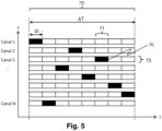
- the waveform of the transmitted signal is shown in figure 5 .
- the signal comprises, during a repetition period 72, a plurality of pulses 70.
- Each pulse 70 is transmitted in a different transmission frequency channel 73 and during a time interval 71 different from the repetition period. repetition 72.
- the transmission of the plurality of pulses is repeated at each repetition period 72.
- the duration of a pulse 70 is denoted ⁇ t.
- the duration of a repetition period 72 is denoted ⁇ T.
- each pulse 70 is associated with a transmission frequency channel 73 and a time interval 71 in the repetition period 72, and there are a plurality of pulses 70 having two by two a transmission frequency channel 73 and a different time interval 71 during a repetition period 72.
- a time interval 71 during which a pulse 70 is transmitted is shown in black.
- Such arrangements make it possible to maintain a virtually constant power envelope and thus to optimize the ratio between the average power and the peak power.
- a transmission frequency channel 73 corresponds to a frequency sub-band defined by a transmission frequency and by a bandwidth.
- the widths of the frequency sub-bands of the different transmission frequency channels 73 are not necessarily identical.
- the transmission frequency channels 73 belong to a frequency band and can be arranged uniformly or non-uniformly around a central frequency of said frequency band.
- the different transmission frequency channels 73 are different in the sense that they are disjoint from one another (they are frequency isolated from one another).
- time intervals 71 could have different durations. Also, there is no requirement that the time intervals 71 completely cover the repetition period 72.
- the duration of the repetition period 72 may be defined based on a desired unambiguous maximum distance.
- the duration of the repetition period 72 may be variable over time.
- the method 100 comprises a step 102 of reception, by the receiver device of the radar system, of a signal comprising a reflection of the signal transmitted by a target of which it is sought to estimate a position and/or a speed.
- the received signal generally also comprises noise and clutter.
- the method 100 comprises a step 103 of filtering the signal received by a bank of digital filters.
- Each digital filter has a bandwidth respectively associated with one of the transmission frequency channels 73 and provides at output a signal associated with a reception frequency channel.
- the method 100 then comprises a step of adapted filtering 104 of the signal of each reception frequency channel during an integration sub-period.
- the duration of an integration sub-period corresponds for example to the duration ⁇ T of a repetition period 72.
- a repetition sub-period could however correspond to a fraction of the repetition period 72.
- the duration of an integration sub-period is greater than the duration ⁇ t of a time interval 71.
- the method 100 then comprises a Doppler filtering step 107 of the adapted filtering results obtained for the different reception frequency channels for a plurality of successive integration sub-periods forming a coherent integration period covering several successive repetition periods 72.
- the method 100 then comprises a step 108 of determining a distance and a Doppler direction vector which maximize a signal-to-noise ratio plus clutter for the received signal, then a step 109 of estimating the position and/or the speed of the target from the distance and the Doppler direction vector thus determined.
- the steps of filtering 103 by the digital filter bank, of adapted filtering 104, of Doppler filtering 107, of maximizing the signal-to-noise ratio plus clutter and of estimating 109 the position and/or the speed of the target are for example implemented by a processing unit belonging to the receiver device of the radar system. However, nothing would prevent these steps from being implemented by a processing unit belonging to a physical entity distinct from the receiver device. In this case, digital samples of the signal received by the receiver device are transmitted to said physical entity for processing. The physical entity comprising the processing unit can then be geographically distant from the receiver device of the radar system. In variants, only part of these steps is implemented by a processing unit belonging to the receiver device, and the other part of these steps is implemented by another entity. For example, it is conceivable that only the step 109 of estimating the position and/or speed of the target is implemented by a unit for locating and tracking a target belonging to a physical entity distinct from the receiving device.
- each pulse 70 emitted during a time interval 71 can be carried out independently, and the results of the processing carried out for all 70 pulses during an integration period are combined coherently so as not to degrade the signal-to-noise ratio.
- the N emission frequency channels 73 each have a central frequency equal to f c + ⁇ f ( j ), j ⁇ [0 ; ( N - 1)].
- the pulse Doppler processing can be applied for each frequency channel.
- Each of the channels is active at an instant corresponding to a time period l ( j ) in the integration sub-period 0 ⁇ l ( j ) ⁇ 1.
- all the pulses 70 have the same waveform and therefore the same autocorrelation function (in a variant, the waveforms of the different pulses 70 could however be different from one frequency channel to another).
- the number of coefficients in the optimal Doppler filter is equal to the product of the number of channels with the number of pulses per channel during a coherent integration period.
- the Doppler filtering is performed on the coherent combinations obtained for the different groups, rather than on the set of all the matched filtering results. Such arrangements make it possible to reduce the dimension of the Doppler direction vector to be determined.
- the matched filtering result obtained for a given frequency channel allows to estimate a distance and a phase shift for the corresponding pulse.
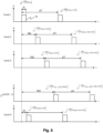
- the figure 6 illustrates how the phase shifts observed for the different 70 pulses transmitted according to the waveform of the figure 5 depend on the transmission frequency channel 73 and the time interval 71 in which each pulse 70 is transmitted.
- FIG 7 represents the main steps of the method 100 described with reference to the figure 4 with further a step 105 of separating the results of adapted filtering into several groups, such that the results of adapted filtering belonging to the same group have substantially equal phase shifts, and a step 106 of coherent combination of the results of adapted filtering of each group.
- FIG 8 illustrates an example of aggregating pulses to compensate for the differential phase shift of the different channels.
- Each pair (frequency channel, time interval) is associated with a number.
- the filtering results for pulses transmitted for pairs (frequency channel, time interval) associated with the same number can be averaged together.
- the phase evolution for the averaged elements is approximately that of the central channels. It is possible to determine a threshold (for example ten degrees of angle) below which phase shifts are considered to be approximately equal. For example, it is possible to use a Keystone transformation to identify the matched filtering results that have a similar phase shift. For the example considered and illustrated in figures 5 And 8 , channels 2 and 4 could be averaged together (there could be others depending on the accepted tolerance on phase error).
- FIG 9 schematically represents an exemplary embodiment of a radar system 10 according to the invention.
- the radar system 10 comprises a transmitter device 20 and a receiver device 30.
- the transmitter device 20 and the receiver device 30 are physically separated.
- the radar system 10 is mono-static, as is the case for example in the system described with reference to the figure 2 , the transmitter device 20 and the receiver device 30 are co-located.
- the transmitter device 20 comprises a processing unit 21 of the DSP type (English acronym for “Digital Signal Processor”) and a transmission chain 23.
- the processing unit 21 comprises a generator module 22 configured to generate a waveform of the type described with reference to the figure 5 .
- the transmission chain 23 comprises a DAC (Digital to Analog Converter) type converter for converting the digital signal provided by the generator 22 into an analog signal.
- the transmission chain 23 also comprises a radio transmission module for transmitting the generated analog signal.
- the transmission chain 23 may comprise several antennas and a beamforming network, for example if STAP processing is envisaged.
- the transmitter device 20 is thus configured to implement the transmission step 101 of the method 100 described with reference to figures 4 And 7 .
- the transmit frequency channels 73 are chosen so that their spectral content has a low level of overlap with each other. This can be achieved by filtering the waveform at transmit, or by generating a intrinsically narrowband pulse, for example by using an apodization window in preconditioning.
- This spectral isolation of the different frequency channels is advantageous because it allows to neglect the cross-correlation terms with respect to the autocorrelation function of a pulse transmitted in a frequency channel. There is, however, a trade-off, because this spectral isolation impacts the width of the temporal support of the signal in each channel, in accordance with the Gabor-Heisenberg uncertainty principle.
- the transmission frequency channels 73 are for example between 94 GHz (gigahertz) and 94.5 GHz, or between 9 GHz and 10 GHz.
- the bandwidth of a frequency channel is for example between 1 MHz (megahertz) and 100 MHz.
- the central frequencies of two different transmission frequency channels 73 are for example separated by at least one time the bandwidth, or even one and a half times the bandwidth.
- the duration of a time interval 71 is for example between 1 ⁇ s (microsecond) and 1 ms (millisecond).
- the number of time intervals 71 included in a repetition period 72 is for example between 8 and 1024. In a particularly advantageous embodiment, there are as many transmission frequency channels 73 as there are time intervals 71 in the repetition period 72, and the time intervals 71 completely cover the repetition period 72.
- the receiving device 30 comprises a reception chain 33, a DSP type processing unit 40 and a localization unit 50.
- the reception chain 33 comprises a radio reception module configured to receive a signal comprising a reflection by a target of the signal transmitted by the transmitter device 20.
- the reception chain 33 comprises an ADC type converter (acronym for “Analog to Digital Converter”) to convert the received analog signal into a digital signal.
- the reception chain 33 can also comprise several antennas and a beamforming network. The reception chain 33 is thus configured to implement the reception step 102 of the method 100.
- the processing unit 40 is a DSP type processor configured by program code instructions stored in a recording medium to implement certain steps of the method 100.
- the processing unit 40 of the receiving device 30 comprises a bank 41 of digital filters 42.
- Each digital filter 42 has a bandwidth associated with one of the transmission frequency channels 73 and provides at output a signal associated with a reception frequency channel.
- the bank 41 of digital filters 42 is thus configured to implement the filtering step 103 of the method 100.
- Each reception frequency channel corresponds to a frequency sub-band similar to that of the associated transmission frequency channel.
- the processing unit 40 of the receiving device 30 comprises a matched filtering module 43 for each reception frequency channel during an integration sub-period.
- the matched filtering module 43 is thus configured to implement the matched filtering step 104 of the method 100.
- the matched filtering produces a correlation peak whose width is approximately equal to the width of the correlation peak of the waveform of a pulse 70.
- the limited duration of the pulses 70 has the consequence that the correlation sidelobes are restricted to a limited time frame around the correlation peak (assuming that the pulses of the other channels do not significantly interfere with the channel of interest).
- the processing unit 40 of the receiving device 30 also comprises a combination module 45 configured to separate the matched filtering results into several groups, such that the matched filtering results belonging to the same group have substantially equal phase shifts, and for each group, to perform a coherent combination of the matched filtering results belonging to said group.
- the combination module 45 is thus configured to implement steps 105 and 106 of the method 100 described with reference to the figure 7 .
- the processing unit 40 of the receiving device 30 comprises a Doppler filtering module 46 configured to perform Doppler filtering of the matched filtering results obtained for a coherent integration period formed of several successive integration sub-periods.
- the Doppler filtering module 46 is also configured to determine a distance and a Doppler direction vector that maximize the signal-to-noise plus clutter ratio SNCR for the received signal.
- the combination module 45 is thus configured to implement step 107 of the method 100.
- the localization unit 50 is configured to estimate the position and/or the speed of the target from the distance and the Doppler direction vector thus determined.
- the localization unit 50 could belong to the processing module 40, or to another physical entity distinct from the receiving device 30. According to yet another variant, the processing unit 40 and the localization unit 50 could both belong to an entity distinct from the receiving device 30.
- the radar system according to the invention make it possible to significantly improve the signal-to-noise plus clutter ratio (SNCR).
- SNCR signal-to-noise plus clutter ratio
- the low level of side lobes induced by the parallel processing of the pulses in fact makes it possible to increase the duty cycle without increasing the contamination of the signal by clutter. This induces a higher SNCR for the same peak power level, or a lower peak power to obtain the same SNCR level.
- the transmission frequency channels and/or the time intervals may vary over time.
- said transmission frequency channel 73 is associated with a time interval 71 that is different from one repetition period 72 to another.
- at least one transmission frequency channel 73 varies from one coherent integration period to another.
- the variation in the order in which the pulses 70 are transmitted in the different transmission frequency channels 73, and/or the variation in the transmission frequency channels 73 themselves make the system less predictable and therefore more resilient to interference. It is also conceivable to vary the durations of the time intervals 71 from one coherent integration period to another.
- the order in which the pulses 70 are transmitted in the different transmission frequency channels 73 for a given repetition period 72 may be completely independent of the order in which the pulses 70 are transmitted in the different transmission frequency channels 73 for the previous repetition period or for the following repetition period.
- Pulses can be modulated or unmodulated. Modulating a pulse allows for a narrower correlation peak and therefore a finer resolution for target detection. Different pulses transmitted in the same repetition period may possibly have different modulations.
Landscapes
- Engineering & Computer Science (AREA)
- Radar, Positioning & Navigation (AREA)
- Remote Sensing (AREA)
- Physics & Mathematics (AREA)
- Computer Networks & Wireless Communication (AREA)
- General Physics & Mathematics (AREA)
- Electromagnetism (AREA)
- Spectroscopy & Molecular Physics (AREA)
- Radar Systems Or Details Thereof (AREA)
Claims (16)
- Verfahren (100) zum Betreiben eines Radarsystems (10), wobei das Verfahren (100) enthält:- eine Übertragung (101) eines Signals, das, während einer Wiederholungsperiode (72), eine Vielzahl von Impulsen (70) umfasst, wobei jeder Impuls (70) in einem anderen Sendefrequenzkanal (73) und während eines anderen Zeitintervalls (71) übertragen wird,- einen Empfang (102) eines Signals, das eine Reflexion des gesendeten Signals von einem Ziel (60) umfasst, von dem eine Position und/oder eine Geschwindigkeit geschätzt werden soll, wobei das empfangene Signal auch Rauschen und Clutter umfasst,- eine Filterung (103) des empfangenen Signals durch eine Bank von digitalen Filtern, wobei jedes digitale Filter jeweils eine Bandbreite aufweist, die einem der Sendefrequenzkanäle (73) zugeordnet ist, und als Ausgang ein Signal bereitstellt, das einem Empfangsfrequenzkanal zugeordnet ist,- eine angepasste Filterung (104) des Signals jedes Empfangsfrequenzkanals während einer Integrations-Teilperiode,- eine Aufteilung (105) der Ergebnisse der angepassten Filterung in mehrere Gruppen, so dass die Ergebnisse der angepassten Filterung, die zu einer selben Gruppe gehören, im Wesentlichen gleiche Phasenverschiebungen aufweisen,- für jede Gruppe, eine kohärente Kombination (106) der Ergebnisse der angepassten Filterung, die zur Gruppe gehören,- eine Doppler-Filterung (107) der Ergebnisse der angepassten Filterung, die für die verschiedenen Empfangsfrequenzkanäle für mehrere aufeinanderfolgende Integrations-Teilperioden erhalten wurden, die eine kohärente Integrationsperiode bilden, die mehrere aufeinanderfolgende Wiederholungsperioden (72) abdeckt, wobei die Doppler-Filterung (107) auf den kohärenten Kombinationen basiert, die für die verschiedenen Gruppen erhalten wurden,- eine Bestimmung (108) eines Abstands und eines Doppler-Richtungsvektors, die ein Signal-Rausch-Verhältnis plus Clutter für das empfangene Signal maximieren,- eine Schätzung (109) der Position und/oder der Geschwindigkeit des Ziels (60) ausgehend vom Abstand und dem Doppler-Richtungsvektor, die so ermittelt wurden.
- Verfahren (100) nach Anspruch 1, wobei in der Wiederholungsperiode (72) so viele Sendefrequenzkanäle (73) wie Zeitintervalle (71) vorhanden sind, und die Zeitintervalle (71) die Wiederholungsperiode (72) vollständig abdecken.
- Verfahren (100) nach einem der Ansprüche 1 bis 2, wobei, für mindestens einen Sendefrequenzkanal (73), der Sendefrequenzkanal (73) einem Zeitintervall (71) zugeordnet ist, das sich von einer Wiederholungsperiode (72) zu einer anderen unterscheidet.
- Verfahren (100) nach einem der Ansprüche 1 bis 3, wobei mindestens ein Sendefrequenzkanal (73) von einer kohärenten Integrationsperiode zu einer anderen variiert.
- Verfahren (100) nach einem der Ansprüche 1 bis 4, wobei, für mindestens ein gegebenes Zeitintervall (71), mehrere Impulse (70) in verschiedenen Sendefrequenzkanälen (73) übertragen werden.
- Verfahren (100) nach einem der Ansprüche 1 bis 5, wobei die Sendefrequenzkanäle (73) zwischen 94 GHz und 94,5 GHz liegen oder zwischen 9 GHz und 10 GHz.
- Verfahren (100) nach einem der Ansprüche 1 bis 6, wobei die Bandbreite eines Frequenzkanals zwischen 1 MHz und 100 MHz liegt, und die Mittenfrequenzen von zwei verschiedenen Sendefrequenzkanälen (73) um mindestens einmal die Bandbreite voneinander getrennt sind.
- Verfahren (100) nach einem der Ansprüche 1 bis 7, wobei die Dauer eines Zeitintervalls (71) zwischen 1 µs und 1 ms liegt.
- Verfahren (100) nach Anspruch 8, wobei die Anzahl der Zeitintervalle (71) innerhalb einer Wiederholungsperiode (72) zwischen 8 und 1024 liegt.
- Radarsystem (10) umfassend:- eine Emittiervorrichtung (20), die zum Übertragen eines Signals konfiguriert ist, das, während einer Wiederholungsperiode (72), eine Vielzahl von Impulsen (70) umfasst, wobei jeder Impuls (70) in einem anderen Sendefrequenzkanal (73) und während eines anderen Zeitintervalls (71) übertragen wird,- eine Empfangsvorrichtung (30), die zum Empfangen eines Signals konfiguriert ist, das eine Reflexion des gesendeten Signals von einem Ziel (60) umfasst, von dem eine Position und/oder eine Geschwindigkeit geschätzt werden soll, wobei das empfangene Signal auch Rauschen und Clutter umfasst,- eine Verarbeitungseinheit (40), umfassend:∘ eine Bank (41) von digitalen Filtern (42), die konfiguriert ist, um eine Filterung des empfangenen Signals durchzuführen, wobei jedes digitale Filter (42) jeweils eine Bandbreite aufweist, die einem der Sendefrequenzkanäle (73) zugeordnet ist, und als Ausgang ein Signal bereitstellt, das einem Empfangsfrequenzkanal zugeordnet ist,∘ ein Modul der angepassten Filterung (43), das konfiguriert ist, um eine angepasste Filterung des Signals jedes Empfangsfrequenzkanals während einer Integrations-Teilperiode durchzuführen,∘ ein Kombinationsmodul (45), das konfiguriert ist, um die Ergebnisse der angepassten Filterung in mehrere Gruppen aufzuteilen, so dass die Ergebnisse der angepassten Filterung, die zu einer selben Gruppe gehören, im Wesentlichen gleiche Phasenverschiebungen aufweisen, und, für jede Gruppe, eine kohärente Kombination der Ergebnisse der angepassten Filterung durchzuführen, die zu dieser Gruppe gehören,∘ ein Modul der Doppler-Filterung (46), das konfiguriert ist, um eine Doppler-Filterung der Ergebnisse der angepassten Filterung durchzuführen, die für die verschiedenen Empfangsfrequenzkanäle für mehrere aufeinanderfolgende Integrations-Teilperioden erhalten wurden, die eine kohärente Integrationsperiode bilden, die mehrere aufeinanderfolgende Wiederholungsperioden (72) abdeckt, wobei die Doppler-Filterung auf den am Ausgang des Kombinationsmoduls (45) erhaltenen Kombinationen basiert, und um einen Abstand und einen Doppler-Richtungsvektor zu bestimmen, die ein Signal-Rausch-Verhältnis plus Clutter für das empfangene Signal maximieren,- eine Lokalisierungseinheit (50), die konfiguriert ist, um die Position und/oder die Geschwindigkeit des Ziels (60) zu schätzen, ausgehend vom Abstand und dem Doppler-Richtungsvektor, die so ermittelt wurden.
- Radarsystem (10) nach Anspruch 10, wobei in der Wiederholungsperiode (72) so viele Sendefrequenzkanäle (73) wie Zeitintervalle (71) vorhanden sind, und die Zeitintervalle (71) die Wiederholungsperiode (72) vollständig abdecken.
- Radarsystem (10) nach einem der Ansprüche 10 bis 11, wobei das Radarsystem (10) bistatisch ist, wobei die Emittiervorrichtung (20) und die Empfangsvorrichtung (30) voneinander getrennt sind.
- Radarsystem (10) nach Anspruch 12, wobei die Emittiervorrichtung (20) dazu bestimmt ist, in einen Satelliten (25) in einer Erdumlaufbahn (90) eingebaut zu werden, wobei das Radarsystem (10) zur Luftüberwachung bestimmt ist.
- Radarsystem (10) nach einem der Ansprüche 10 bis 11, wobei das Radarsystem (10) ein monostatisches Radarsystem ist, das dazu bestimmt ist, in einen Satelliten (25) in einer Erdumlaufbahn (90) eingebaut zu werden, wobei das Radarsystem (10) zur Wetterüberwachung bestimmt ist.
- Verarbeitungseinheit (40) eines Radarsystems (10) zur Verarbeitung eines von einer Empfangsvorrichtung (30) des Radarsystems (10) empfangenen Signals, wobei das empfangene Signal eine Reflexion eines Signals umfasst, das von einer Emittiervorrichtung (20) des Radarsystems (10) übertragen wurde, wobei das übertragene Signal, während einer Wiederholungsperiode (72), eine Vielzahl von Impulsen (70) umfasst, wobei jeder Impuls (70) in einem anderen Sendefrequenzkanal (73) und während eines anderen Zeitintervalls (71) übertragen wird, wobei das empfangene Signal auch Rauschen und Clutter umfasst, wobei die Verarbeitungseinheit (40) umfasst:- eine Bank (41) von digitalen Filtern (42), die konfiguriert ist, um das empfangene Signal zu filtern, wobei jedes digitale Filter (42) jeweils eine Bandbreite aufweist, die einem der Sendefrequenzkanäle (73) zugeordnet ist, und als Ausgang ein Signal bereitstellt, das einem Empfangsfrequenzkanal zugeordnet ist,- ein Modul der angepassten Filterung (43), das konfiguriert ist, um eine angepasste Filterung des Signals jedes Empfangsfrequenzkanals während einer Integrations-Teilperiode durchzuführen,- ein Kombinationsmodul (45), das konfiguriert ist, um die Ergebnisse der angepassten Filterung in mehrere Gruppen aufzuteilen, so dass die Ergebnisse der angepassten Filterung, die zu einer selben Gruppe gehören, im Wesentlichen gleiche Phasenverschiebungen aufweisen, und, für jede Gruppe, eine kohärente Kombination der Ergebnisse der angepassten Filterung durchzuführen, die zu dieser Gruppe gehören,- ein Modul der Doppler-Filterung (46), das konfiguriert ist, um eine Doppler-Filterung der Ergebnisse der angepassten Filterung durchzuführen, die für die verschiedenen Empfangsfrequenzkanäle für mehrere aufeinanderfolgende Integrations-Teilperioden erhalten wurden, die eine kohärente Integrationsperiode bilden, die mehrere aufeinanderfolgende Wiederholungsperioden (72) abdeckt, wobei die Doppler-Filterung auf den am Ausgang des Kombinationsmoduls (45) erhaltenen Kombinationen basiert, und um einen Abstand und einen Doppler-Richtungsvektor zu bestimmen, die ein Signal-Rausch-Verhältnis plus Clutter für das empfangene Signal maximieren.
- Computerlesbares Aufzeichnungsmedium, Anweisungen umfassend, die dazu bestimmt sind, durch eine Verarbeitungseinheit (40) eines Radarsystems (10) ausgeführt zu werden, um ein Signal zu verarbeiten, das von einer Empfangsvorrichtung (30) des Radarsystems (10) empfangen wurde, wobei das empfangene Signal eine Reflexion eines Signals umfasst, das von einer Emittiervorrichtung (20) des Radarsystems (10) übertragen wurde, wobei das übertragene Signal, während einer Wiederholungsperiode (72), eine Vielzahl von Impulsen (70) umfasst, wobei jeder Impuls (70) in einem anderen Sendefrequenzkanal (73) und während eines anderen Zeitintervalls (71) übertragen wird, wobei das empfangene Signal auch Rauschen und Clutter umfasst, wobei die Anweisungen die Verarbeitungseinheit (40) veranlassen zum:- Filtern des empfangenen Signals durch eine Reihe von digitalen Filtern (42), wobei jedes digitale Filter (42) jeweils eine Bandbreite aufweist, die einem der Sendefrequenzkanäle (73) zugeordnet ist, und als Ausgang ein Signal bereitstellt, das einem Empfangsfrequenzkanal zugeordnet ist,- Durchführen einer angepassten Filterung des Signals jedes Empfangsfrequenzkanals während einer Integrations-Teilperiode,- Aufteilen der Ergebnisse der angepassten Filterung in mehrere Gruppen, so dass die Ergebnisse der angepassten Filterung, die zu einer selben Gruppe gehören, im Wesentlichen gleiche Phasenverschiebungen aufweisen,- für jede Gruppe, Kombinieren, auf kohärente Weise, der Ergebnisse der angepassten Filterung, die zur Gruppe gehören,- Durchführen einer Doppler-Filterung der Ergebnisse der angepassten Filterung, die für die verschiedenen Empfangsfrequenzkanäle für mehrere aufeinanderfolgende Integrations-Teilperioden erhalten wurden, die eine kohärente Integrationsperiode bilden, die mehrere aufeinanderfolgende Wiederholungsperioden (72) abdeckt, wobei die Doppler-Filterung auf den erhaltenen Kombinationen basiert,- Bestimmen eines Abstands und eines Doppler-Richtungsvektors, die ein Signal-Rausch-Verhältnis plus Clutter für das empfangene Signal maximieren.
Applications Claiming Priority (2)
| Application Number | Priority Date | Filing Date | Title |
|---|---|---|---|
| FR2202279A FR3133678B1 (fr) | 2022-03-17 | 2022-03-17 | Système radar et procédé associé pour optimiser l'élimination de fouillis radar |
| PCT/EP2023/055912 WO2023174774A1 (fr) | 2022-03-17 | 2023-03-08 | Système radar et procédé associé pour optimiser l'élimination de fouillis radar |
Publications (3)
| Publication Number | Publication Date |
|---|---|
| EP4330722A1 EP4330722A1 (de) | 2024-03-06 |
| EP4330722B1 true EP4330722B1 (de) | 2024-10-23 |
| EP4330722C0 EP4330722C0 (de) | 2024-10-23 |
Family
ID=83188825
Family Applications (1)
| Application Number | Title | Priority Date | Filing Date |
|---|---|---|---|
| EP23709219.2A Active EP4330722B1 (de) | 2022-03-17 | 2023-03-08 | Radarsystem und zugehöriges verfahren zur optimierung der beseitigung von radarstörungen |
Country Status (3)
| Country | Link |
|---|---|
| EP (1) | EP4330722B1 (de) |
| FR (1) | FR3133678B1 (de) |
| WO (1) | WO2023174774A1 (de) |
Family Cites Families (3)
| Publication number | Priority date | Publication date | Assignee | Title |
|---|---|---|---|---|
| FR2970085A1 (fr) * | 2010-12-30 | 2012-07-06 | Thales Sa | Procede d'extension de la portee instrumentee d'un radar |
| FR3026194B1 (fr) * | 2014-09-24 | 2018-01-26 | Thales Sa | Forme d'onde radar, procede de detection radar utilisant une telle onde, et radar mettant en oeuvre le procede |
| FR3113951A1 (fr) * | 2020-09-10 | 2022-03-11 | Airbus Defence And Space Sas | Système radar bi-statique ou multi-statique pour la surveillance aérienne avec illumination spatiale |
-
2022
- 2022-03-17 FR FR2202279A patent/FR3133678B1/fr active Active
-
2023
- 2023-03-08 WO PCT/EP2023/055912 patent/WO2023174774A1/fr not_active Ceased
- 2023-03-08 EP EP23709219.2A patent/EP4330722B1/de active Active
Also Published As
| Publication number | Publication date |
|---|---|
| FR3133678B1 (fr) | 2024-04-12 |
| FR3133678A1 (fr) | 2023-09-22 |
| WO2023174774A1 (fr) | 2023-09-21 |
| EP4330722A1 (de) | 2024-03-06 |
| EP4330722C0 (de) | 2024-10-23 |
Similar Documents
| Publication | Publication Date | Title |
|---|---|---|
| EP0818691B1 (de) | Verfahren und Vorrichtung zur Zielerfassung für Doppler Radargeräte mit Hilfe von breitbandigen eindeutigen Pulsen | |
| EP2296006B1 (de) | Breitband-Flugzeugradarvorrichtung mit großem Erfassungswinkel, insbesondere für die Funktion der Kollisionsvermeidung | |
| EP2831615B1 (de) | Vorrichtung für aktive und passive elektromagnetische detektion mit geringer wahrscheinlichkeit von unterbrechungen | |
| EP2287633B1 (de) | Radar zur Erkennung von Luftzielen, der als Ausrüstung eines Luftfahrzeugs dient, insbesondere zur Hindernisumfliegung | |
| EP2339369B1 (de) | Radarortungsverfahren insbesondere für Bordradargeräte zur Umsetzung einer Hinderniserfassungs- und -vermeidungsfunktion | |
| EP0681190B1 (de) | System und Verfahren zur diskreten Radarerkennung | |
| EP2410352A1 (de) | Antennenvorrichtung mit synthetischer Öffnung zum Empfang von Signalen eines Systems, das eine Trägerwelle und Mittel zur Bestimmung ihrer Verlaufsbahn umfasst | |
| EP4165435B1 (de) | Bistatisches oder multistatisches radarsystem zur luftüberwachung mit räumlicher beleuchtung | |
| EP2544020B1 (de) | Verfahren und Vorrichtung zur Detektion eines Ziels, das von starken Energiereflektoren maskiert wird | |
| FR2998975A1 (fr) | Procede de filtrage, dans un signal radar, des ambiguites distance par codage d'impulsions et traitement multi-voies | |
| WO2021219398A1 (fr) | Procédé d'imagerie radar, et radar mettant en œuvre un tel procédé | |
| EP3198299B1 (de) | Radardetektionsverfahren und radar zur implementierung des besagten verfahrens | |
| EP3605145A1 (de) | Hochauflösendes fernverarbeitungsverfahren | |
| EP4330722B1 (de) | Radarsystem und zugehöriges verfahren zur optimierung der beseitigung von radarstörungen | |
| EP3538916B1 (de) | Verfahren zum testen der elektromagnetischen verträglichkeit eines radardetektors mit mindestens einem impulssignalsender an bord | |
| EP3859882A1 (de) | Funksystem mit mehreren antennennetzwerken und adaptiven wellenformen | |
| EP3400457B1 (de) | Verfahren zum löschen eines signals aus einem bordradar | |
| EP4671824A1 (de) | Verfahren zum betrieb eines radars nach einem apertursynthese- und einem zweiten betriebsmodus mit zufallsphasen und radar dafür | |
| EP4671823A1 (de) | Verfahren zum betreiben eines sensorradars und sensorradar dafür | |
| EP4671807A1 (de) | Verfahren zum betreiben eines sensorradars und sensorradar dafür | |
| FR3164026A1 (fr) | Procédé de fonctionnement d'un radar de détection suivant plusieurs configurations de détection dans un mode météo et radar de détection associé | |
| EP3538917B1 (de) | Verfahren zum testen der elektromagnetischen verträglichkeit eines radardetektors mit mindestens einem impulssignalgeber an bord | |
| FR3164021A1 (fr) | Proccédé de fonctionnement d'un radar de détection suivant plusieurs configurations de détection et radar de détection associé | |
| EP3538919B1 (de) | Verfahren zum testen der elektromagnetischen verträglichkeit eines radardetektors mit mindestens einem impulssignalgeber an bord | |
| FR3164023A1 (fr) | Procédé de fonctionnement d'un radar de détection et radar de détection associé |
Legal Events
| Date | Code | Title | Description |
|---|---|---|---|
| STAA | Information on the status of an ep patent application or granted ep patent |
Free format text: STATUS: UNKNOWN |
|
| STAA | Information on the status of an ep patent application or granted ep patent |
Free format text: STATUS: THE INTERNATIONAL PUBLICATION HAS BEEN MADE |
|
| PUAI | Public reference made under article 153(3) epc to a published international application that has entered the european phase |
Free format text: ORIGINAL CODE: 0009012 |
|
| STAA | Information on the status of an ep patent application or granted ep patent |
Free format text: STATUS: REQUEST FOR EXAMINATION WAS MADE |
|
| 17P | Request for examination filed |
Effective date: 20231130 |
|
| AK | Designated contracting states |
Kind code of ref document: A1 Designated state(s): AL AT BE BG CH CY CZ DE DK EE ES FI FR GB GR HR HU IE IS IT LI LT LU LV MC ME MK MT NL NO PL PT RO RS SE SI SK SM TR |
|
| GRAP | Despatch of communication of intention to grant a patent |
Free format text: ORIGINAL CODE: EPIDOSNIGR1 |
|
| STAA | Information on the status of an ep patent application or granted ep patent |
Free format text: STATUS: GRANT OF PATENT IS INTENDED |
|
| INTG | Intention to grant announced |
Effective date: 20240605 |
|
| GRAS | Grant fee paid |
Free format text: ORIGINAL CODE: EPIDOSNIGR3 |
|
| GRAA | (expected) grant |
Free format text: ORIGINAL CODE: 0009210 |
|
| STAA | Information on the status of an ep patent application or granted ep patent |
Free format text: STATUS: THE PATENT HAS BEEN GRANTED |
|
| AK | Designated contracting states |
Kind code of ref document: B1 Designated state(s): AL AT BE BG CH CY CZ DE DK EE ES FI FR GB GR HR HU IE IS IT LI LT LU LV MC ME MK MT NL NO PL PT RO RS SE SI SK SM TR |
|
| DAV | Request for validation of the european patent (deleted) | ||
| DAX | Request for extension of the european patent (deleted) | ||
| REG | Reference to a national code |
Ref country code: GB Ref legal event code: FG4D Free format text: NOT ENGLISH |
|
| REG | Reference to a national code |
Ref country code: CH Ref legal event code: EP |
|
| REG | Reference to a national code |
Ref country code: DE Ref legal event code: R096 Ref document number: 602023000822 Country of ref document: DE |
|
| REG | Reference to a national code |
Ref country code: IE Ref legal event code: FG4D Free format text: LANGUAGE OF EP DOCUMENT: FRENCH |
|
| U01 | Request for unitary effect filed |
Effective date: 20241029 |
|
| U07 | Unitary effect registered |
Designated state(s): AT BE BG DE DK EE FI FR IT LT LU LV MT NL PT RO SE SI Effective date: 20241108 |
|
| PG25 | Lapsed in a contracting state [announced via postgrant information from national office to epo] |
Ref country code: HR Free format text: LAPSE BECAUSE OF FAILURE TO SUBMIT A TRANSLATION OF THE DESCRIPTION OR TO PAY THE FEE WITHIN THE PRESCRIBED TIME-LIMIT Effective date: 20241023 Ref country code: IS Free format text: LAPSE BECAUSE OF FAILURE TO SUBMIT A TRANSLATION OF THE DESCRIPTION OR TO PAY THE FEE WITHIN THE PRESCRIBED TIME-LIMIT Effective date: 20250223 |
|
| PG25 | Lapsed in a contracting state [announced via postgrant information from national office to epo] |
Ref country code: ES Free format text: LAPSE BECAUSE OF FAILURE TO SUBMIT A TRANSLATION OF THE DESCRIPTION OR TO PAY THE FEE WITHIN THE PRESCRIBED TIME-LIMIT Effective date: 20241023 |
|
| PG25 | Lapsed in a contracting state [announced via postgrant information from national office to epo] |
Ref country code: NO Free format text: LAPSE BECAUSE OF FAILURE TO SUBMIT A TRANSLATION OF THE DESCRIPTION OR TO PAY THE FEE WITHIN THE PRESCRIBED TIME-LIMIT Effective date: 20250123 |
|
| PG25 | Lapsed in a contracting state [announced via postgrant information from national office to epo] |
Ref country code: GR Free format text: LAPSE BECAUSE OF FAILURE TO SUBMIT A TRANSLATION OF THE DESCRIPTION OR TO PAY THE FEE WITHIN THE PRESCRIBED TIME-LIMIT Effective date: 20250124 |
|
| PG25 | Lapsed in a contracting state [announced via postgrant information from national office to epo] |
Ref country code: PL Free format text: LAPSE BECAUSE OF FAILURE TO SUBMIT A TRANSLATION OF THE DESCRIPTION OR TO PAY THE FEE WITHIN THE PRESCRIBED TIME-LIMIT Effective date: 20241023 |
|
| PG25 | Lapsed in a contracting state [announced via postgrant information from national office to epo] |
Ref country code: RS Free format text: LAPSE BECAUSE OF FAILURE TO SUBMIT A TRANSLATION OF THE DESCRIPTION OR TO PAY THE FEE WITHIN THE PRESCRIBED TIME-LIMIT Effective date: 20250123 |
|
| U20 | Renewal fee for the european patent with unitary effect paid |
Year of fee payment: 3 Effective date: 20250325 |
|
| PG25 | Lapsed in a contracting state [announced via postgrant information from national office to epo] |
Ref country code: SM Free format text: LAPSE BECAUSE OF FAILURE TO SUBMIT A TRANSLATION OF THE DESCRIPTION OR TO PAY THE FEE WITHIN THE PRESCRIBED TIME-LIMIT Effective date: 20241023 |
|
| PG25 | Lapsed in a contracting state [announced via postgrant information from national office to epo] |
Ref country code: SK Free format text: LAPSE BECAUSE OF FAILURE TO SUBMIT A TRANSLATION OF THE DESCRIPTION OR TO PAY THE FEE WITHIN THE PRESCRIBED TIME-LIMIT Effective date: 20241023 |
|
| PG25 | Lapsed in a contracting state [announced via postgrant information from national office to epo] |
Ref country code: CZ Free format text: LAPSE BECAUSE OF FAILURE TO SUBMIT A TRANSLATION OF THE DESCRIPTION OR TO PAY THE FEE WITHIN THE PRESCRIBED TIME-LIMIT Effective date: 20241023 |
|
| PLBE | No opposition filed within time limit |
Free format text: ORIGINAL CODE: 0009261 |
|
| STAA | Information on the status of an ep patent application or granted ep patent |
Free format text: STATUS: NO OPPOSITION FILED WITHIN TIME LIMIT |
|
| 26N | No opposition filed |
Effective date: 20250724 |
|
| PG25 | Lapsed in a contracting state [announced via postgrant information from national office to epo] |
Ref country code: MC Free format text: LAPSE BECAUSE OF FAILURE TO SUBMIT A TRANSLATION OF THE DESCRIPTION OR TO PAY THE FEE WITHIN THE PRESCRIBED TIME-LIMIT Effective date: 20241023 |
|
| U1N | Appointed representative for the unitary patent procedure changed after the registration of the unitary effect |
Representative=s name: SANTARELLI; FR |
|
| PG25 | Lapsed in a contracting state [announced via postgrant information from national office to epo] |
Ref country code: IE Free format text: LAPSE BECAUSE OF NON-PAYMENT OF DUE FEES Effective date: 20250308 |