EP2296263A2 - Appareil pour commande de moteur d'un climatiseur et son procédé de commande - Google Patents
Appareil pour commande de moteur d'un climatiseur et son procédé de commande Download PDFInfo
- Publication number
- EP2296263A2 EP2296263A2 EP10008242A EP10008242A EP2296263A2 EP 2296263 A2 EP2296263 A2 EP 2296263A2 EP 10008242 A EP10008242 A EP 10008242A EP 10008242 A EP10008242 A EP 10008242A EP 2296263 A2 EP2296263 A2 EP 2296263A2
- Authority
- EP
- European Patent Office
- Prior art keywords
- mechanical angle
- mechanical
- motor
- angle
- speed
- Prior art date
- Legal status (The legal status is an assumption and is not a legal conclusion. Google has not performed a legal analysis and makes no representation as to the accuracy of the status listed.)
- Granted
Links
- 238000000034 method Methods 0.000 title claims abstract description 37
- 230000004044 response Effects 0.000 claims abstract description 65
- 230000003247 decreasing effect Effects 0.000 abstract description 4
- 239000003507 refrigerant Substances 0.000 description 10
- 230000002159 abnormal effect Effects 0.000 description 9
- 238000001816 cooling Methods 0.000 description 5
- 238000001514 detection method Methods 0.000 description 5
- 239000003990 capacitor Substances 0.000 description 4
- 238000010586 diagram Methods 0.000 description 4
- 230000009467 reduction Effects 0.000 description 3
- 230000008901 benefit Effects 0.000 description 2
- 239000000470 constituent Substances 0.000 description 2
- 238000010438 heat treatment Methods 0.000 description 2
- 230000004048 modification Effects 0.000 description 2
- 238000012986 modification Methods 0.000 description 2
- 230000005855 radiation Effects 0.000 description 2
- 230000008859 change Effects 0.000 description 1
- 238000006243 chemical reaction Methods 0.000 description 1
- 230000006835 compression Effects 0.000 description 1
- 238000007906 compression Methods 0.000 description 1
- 230000001419 dependent effect Effects 0.000 description 1
- 230000006872 improvement Effects 0.000 description 1
- 230000000737 periodic effect Effects 0.000 description 1
- 230000001360 synchronised effect Effects 0.000 description 1
Images


Classifications
-
- H—ELECTRICITY
- H02—GENERATION; CONVERSION OR DISTRIBUTION OF ELECTRIC POWER
- H02P—CONTROL OR REGULATION OF ELECTRIC MOTORS, ELECTRIC GENERATORS OR DYNAMO-ELECTRIC CONVERTERS; CONTROLLING TRANSFORMERS, REACTORS OR CHOKE COILS
- H02P6/00—Arrangements for controlling synchronous motors or other dynamo-electric motors using electronic commutation dependent on the rotor position; Electronic commutators therefor
- H02P6/14—Electronic commutators
- H02P6/16—Circuit arrangements for detecting position
- H02P6/18—Circuit arrangements for detecting position without separate position detecting elements
-
- H—ELECTRICITY
- H02—GENERATION; CONVERSION OR DISTRIBUTION OF ELECTRIC POWER
- H02P—CONTROL OR REGULATION OF ELECTRIC MOTORS, ELECTRIC GENERATORS OR DYNAMO-ELECTRIC CONVERTERS; CONTROLLING TRANSFORMERS, REACTORS OR CHOKE COILS
- H02P21/00—Arrangements or methods for the control of electric machines by vector control, e.g. by control of field orientation
- H02P21/14—Estimation or adaptation of machine parameters, e.g. flux, current or voltage
- H02P21/18—Estimation of position or speed
-
- H—ELECTRICITY
- H02—GENERATION; CONVERSION OR DISTRIBUTION OF ELECTRIC POWER
- H02P—CONTROL OR REGULATION OF ELECTRIC MOTORS, ELECTRIC GENERATORS OR DYNAMO-ELECTRIC CONVERTERS; CONTROLLING TRANSFORMERS, REACTORS OR CHOKE COILS
- H02P21/00—Arrangements or methods for the control of electric machines by vector control, e.g. by control of field orientation
- H02P21/24—Vector control not involving the use of rotor position or rotor speed sensors
- H02P21/26—Rotor flux based control
-
- H—ELECTRICITY
- H02—GENERATION; CONVERSION OR DISTRIBUTION OF ELECTRIC POWER
- H02P—CONTROL OR REGULATION OF ELECTRIC MOTORS, ELECTRIC GENERATORS OR DYNAMO-ELECTRIC CONVERTERS; CONTROLLING TRANSFORMERS, REACTORS OR CHOKE COILS
- H02P25/00—Arrangements or methods for the control of AC motors characterised by the kind of AC motor or by structural details
- H02P25/02—Arrangements or methods for the control of AC motors characterised by the kind of AC motor or by structural details characterised by the kind of motor
- H02P25/08—Reluctance motors
- H02P25/098—Arrangements for reducing torque ripple
-
- H—ELECTRICITY
- H02—GENERATION; CONVERSION OR DISTRIBUTION OF ELECTRIC POWER
- H02P—CONTROL OR REGULATION OF ELECTRIC MOTORS, ELECTRIC GENERATORS OR DYNAMO-ELECTRIC CONVERTERS; CONTROLLING TRANSFORMERS, REACTORS OR CHOKE COILS
- H02P6/00—Arrangements for controlling synchronous motors or other dynamo-electric motors using electronic commutation dependent on the rotor position; Electronic commutators therefor
- H02P6/10—Arrangements for controlling torque ripple, e.g. providing reduced torque ripple
-
- F—MECHANICAL ENGINEERING; LIGHTING; HEATING; WEAPONS; BLASTING
- F25—REFRIGERATION OR COOLING; COMBINED HEATING AND REFRIGERATION SYSTEMS; HEAT PUMP SYSTEMS; MANUFACTURE OR STORAGE OF ICE; LIQUEFACTION SOLIDIFICATION OF GASES
- F25B—REFRIGERATION MACHINES, PLANTS OR SYSTEMS; COMBINED HEATING AND REFRIGERATION SYSTEMS; HEAT PUMP SYSTEMS
- F25B49/00—Arrangement or mounting of control or safety devices
- F25B49/02—Arrangement or mounting of control or safety devices for compression type machines, plants or systems
- F25B49/025—Motor control arrangements
-
- H—ELECTRICITY
- H02—GENERATION; CONVERSION OR DISTRIBUTION OF ELECTRIC POWER
- H02P—CONTROL OR REGULATION OF ELECTRIC MOTORS, ELECTRIC GENERATORS OR DYNAMO-ELECTRIC CONVERTERS; CONTROLLING TRANSFORMERS, REACTORS OR CHOKE COILS
- H02P2203/00—Indexing scheme relating to controlling arrangements characterised by the means for detecting the position of the rotor
- H02P2203/09—Motor speed determination based on the current and/or voltage without using a tachogenerator or a physical encoder
Definitions
- the present invention relates to an apparatus for driving a motor of an air conditioner and a method for driving the same, and more particularly to an apparatus for driving a motor to decrease a speed ripple when the motor is driven at a constant speed, and a method for driving the same.
- an air conditioner is arranged at any indoor space or wall of a room, a living room, an office, a store, etc. to adjust temperature, humidity, cleanness, and flow of indoor air, such that a pleasant indoor environment can be maintained in each indoor space.
- the air conditioner is classified into an integration-type air conditioner and a separation-type air conditioner.
- the integration-type air conditioner has the same function as that of the separation-type air conditioner. However, there are a few differences between them. That is, the integration-type air conditioner integrates a cooling function and a heat-radiation function into one structure, and is directly mounted to a wall via a hole formed in the wall or is directly hung on a window.
- the separation-type air conditioner includes an indoor unit that is installed indoors to heat/cool indoor air, and an outdoor unit that is installed outdoors to perform a heat-radiation function and a compression function.
- the indoor unit and the outdoor unit are interconnected via a refrigerant pipe.
- a motor is used for a compressor, a fan, etc. of the air conditioner, and a driving device for driving the motor (i.e., a motor driving device) is also used for the air conditioner.
- the motor driving device receives commercial AC power as an input, converts the commercial AC power into a DC voltage, converts the DC voltage into other commercial AC power having a predetermined frequency, and provides the other commercial AC power to the motor, such that a compressor, a fan, etc. of the air conditioner can be driven.
- the present invention is directed to an apparatus and method for driving a motor for use in an air conditioner that substantially obviate one or more problems due to limitations and disadvantages of the related art.
- the present invention has been made in view of the above problems, and it is an object of the present invention to provide an apparatus for driving a compressor of an air conditioner so as to minimize a speed ripple of a motor used for driving the compressor.
- a method for driving a motor of an air conditioner including driving the motor in response to a predetermined speed command, sequentially detecting first and second mechanical angles in response to the speed command or a reference speed being spaced apart from the speed command by a predetermined range, calculating a maximum speed mechanical angle corresponding to a maximum speed ripple of the motor on the basis of the detected first and second mechanical angles, and compensating for load torque of the motor on the basis of the calculated the maximum speed mechanical angle.
- an apparatus for driving a motor for use in an air conditioner includes a motor; an inverter that includes a plurality of switching elements, outputs AC power having a predetermined frequency and a predetermined magnitude by a switching operation of the switching elements, and drives the motor; and a controller configured to drive the motor in response to a predetermined speed command, sequentially detect first and second mechanical angles in response to the speed command or a reference speed being spaced apart from the speed command by a predetermined range, calculate a maximum speed mechanical angle corresponding to a maximum speed ripple of the motor on the basis of the detected first and second mechanical angles, and compensate for load torque of the motor on the basis of the calculated the maximum speed mechanical angle.
- FIG. 1 is a schematic view illustrating an air conditioner according to an embodiment of the present invention.
- the air conditioner 50 is generally divided into an indoor unit I and an outdoor unit O.
- the indoor unit O may include a compressor 2 for compressing a refrigerant, a compressor driving unit 2b for driving the compressor 2, an outdoor heat-exchanger 4 for radiating heat of the compressed refrigerant, an outdoor ventilator 5 including not only an indoor fan 51 arranged at one side of an outdoor heat-exchanger 4 to expedite heat radiation of refrigerant but also a driving unit 5b to rotate the outdoor fan 5a, an expansion valve 6 for expanding a condensed refrigerant, a cooling/heating switching valve 10 for switching the flow path of the compressed refrigerant, an accumulator 3 for temporarily storing a gaseous refrigerant, removing moisture and foreign matter from the gaseous refrigerant, and transmitting a refrigerant having constant pressure to the compressor 2, and the like.
- the indoor unit I may include an indoor heat-exchanger 8, an indoor ventilator 9, and the like.
- the indoor heat-exchanger 8 is installed indoors to perform the cooling/heating functions.
- the indoor ventilator 9 includes not only an indoor fan 9a installed at one side of the indoor heat-exchanger 8 to expedite heat radiation of refrigerant but also a driving unit 9b to rotate the indoor fan 9a.
- the compressor 2 may be at least one of an inverter compressor or a constant-speed compressor.
- the air conditioner 50 may be configured as a cooling device for cooling indoor air, or may also be configured as a heat-pump to cool or heat the indoor air.
- an apparatus for driving a compressor of an air conditioner may be each driving unit 2b for operating the compressor 2 of the air conditioner, as shown in FIG. 1 .
- FIG. 1 shows one indoor unit I and one outdoor unit O
- the apparatus for driving the compressor of the air conditioner according to the embodiment of the present invention is not limited only thereto, and can also be applied not only to a multi-type air conditioner including a plurality of indoor units and a plurality of outdoor units but also to another air conditioner including one indoor unit and a plurality of outdoor units without departing from the principles and spirit of the present invention.
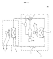
- FIG. 2 is a circuit diagram illustrating an apparatus for driving a compressor of an air conditioner according to an embodiment of the present invention.
- the apparatus for driving the compressor of the air conditioner may include a motor for operating the compressor as previously stated above.
- the compressor driving apparatus may be a load-dependent compressor, operation variation of which is greatly affected by load types, for example, a single-rotary-type compressor.
- a variety of compressors may be applied to the present invention without any restriction, for convenience of description and better understanding of the present invention, the apparatus for driving the compressor according to the embodiment of the present invention will hereinafter be described in detail using a single-rotary compressor as an example.
- the driving apparatus 200 may include a converter 210, an inverter 220, a controller 230, an input current detection unit A, and an output current detector (E).
- the apparatus 200 for driving a motor may further include a capacitor C, a DC-terminal voltage detector B, etc. as necessary.
- a reactor L may be located between a commercial AC power source 205 and a converter 210, such that it performs power factor correction or a step-up (or boost) operation.
- the reactor L may also limit a harmonic current caused by the highspeed switching of the converter 210.
- An input-current detector A may detect an input current (is) received from the commercial AC power source 205.
- a current sensor In order to detect the input current (i s ), a current sensor, a current transformer (CT), a shunt resistor, etc. may be used.
- the detected input current (is) is a pulse-shaped discrete signal, and may be input to the controller 230 to estimate an input voltage (vs) as well as to generate a converter switching control signal (Scc).
- the converter 210 may convert the commercial AC power 205 passing through the reactor L into DC power, and outputs the DC power.
- the commercial AC power 205 of FIG. 2 is shown as a single-phase AC power, it should be noted that the commercial AC power 205 may also be a three-phase AC power as necessary.
- the internal structure of the converter 210 may be changed according to types of the commercial AC power 205. For example, provided that the commercial AC power 205 is the single-phase AC power, a half-bridge converter wherein two switching elements and four diodes are connected to one another may be employed. Provided that the commercial AC power 205 may be the three-phase AC power, 6 switching elements and 6 diodes may be employed.
- the converter 210 may include one or more switching elements, such that it can perform a boosting operation, power factor improvement, and DC-power conversion by the switching operation of the switching elements. Meanwhile, the converter 210 is comprised of a diode and the like, such that it may also perform a rectifying operation without any additional switching operation.
- the capacitor C may be connected to an output terminal of the converter 210.
- the capacitor C smoothes the converted DC power output from the converter 210.
- an output terminal of the converter 210 is hereinafter referred to as a DC terminal or a DC link terminal.
- the DC voltage smoothed in the DC terminal is input to the inverter 220.
- the DC-terminal voltage detector B may detect a DC-terminal voltage (Vdc) of both ends of the capacitor C.
- the DC-terminal voltage detector B may include a resistor, an amplifier, and the like.
- the detected DC-terminal voltage (Vdc) is a pulse-shaped discrete signal, and may be input to the controller 230 to estimate an input voltage (vs) as well as to generate a converter switching control signal (Scc).
- the inverter 220 may include a plurality of inverter switching elements, converts the DC power smoothed by on/off operations of the switching elements into a three-phase AC power, and outputs the resultant three-phase AC power to a three-phase motor 250.
- the inverter 220 may include upper-arm switching elements (Sa, Sb, Sc) and lower-arm switching elements (S'a, S'b, S'c).
- the inverter 220 includes a total of three pairs (Sa&S'a, Sb&S'b, Sc&S'c) of upper-arm and lower-arm switching elements, wherein the three pairs (Sa&S'a, Sb&S'b, Sc&S'c) are connected in parallel to one another.
- one upper-arm switching element (Sa, Sb or Sc) is connected in series to one lower-arm switching element (S'a, S'b or S'c) such that one pair (Sa&S'a, Sb&S'b or Sc&S'c) of upper-arm and lower-arm switching elements is formed.
- One diode is connected in inverse parallel to one switching element (Sa, S'a, Sb, S'b, Sc or S'c)
- the switching elements contained in the inverter 220 receive an inverter switching control signal (Sic) from the controller 230, such that on/off operations of the individual switching elements are performed on the basis of the inverter switching control signal (Sic). As a result, a three-phase AC power having a predetermined frequency is output to the three-phase motor 250.
- Sic inverter switching control signal
- the output current detector (E) may detect an output current (i o ) flowing between the inverter 220 and the three-phase motor 250. In other words, the output current detector (E) detects a current flowing in the motor 250.
- the output current detector E may detect all output currents of individual phases, or may also detect a one-phase or two-phase output current using three-phase equilibrium.
- the output current detector (E) may be located between the inverter 220 and the motor 250.
- a current sensor for current detection, a current sensor, a current transformer (CT), a shunt resistor, or the like may be used as the output current detector (E).
- CT current transformer
- a shunt resistor for example, one end of the shunt resistor may be connected to each of three lower-arm switching elements (S'a, S'b, S'c) of the inverter 220.
- the detected output current (i o ) is a pulse-shaped discrete signal, may be applied to the controller 230, and may be used to estimate an input current on the basis of the detected output current (i o ). In addition, the detected output current (i o ) may be used to generate the inverter switching control signal (Sic).
- the controller 230 may estimate the position of the motor 250 (i.e., the rotor position of the motor 250) on the basis of the output current (i o ) detected by the output current detector (E), and may also calculate the rotating speed of the motor 250. Based on the estimated position and rotating speed of the motor 250, the controller 230 performs a variety of control operations to drive the motor 250 in response to a speed command, generates a pulse-width-modulated inverter switching control signal (Sic), and outputs the resultant inverter switching control signal (Sic).
- Sic pulse-width-modulated inverter switching control signal
- the above-mentioned control operation under the condition that an additional motor position detector element, etc. is not used, for detecting an output current, estimating the position and speed of the motor 250 in response to the output current, and performing feedback control causing the estimated speed to change in response to a speed command is called 'sensorless algorithm-based control'.
- This sensorless algorithm-based control is not performed during the initial driving of the motor 250, and may start operation when the rotating speed of the motor 250 is equal to or higher than a predetermined value.
- the controller 230 in association with the embodiment of the present invention, controls the motor 250 to be driven in response to a predetermined speed command.
- the controller 230 sequentially detects a first mechanical angle and a second mechanical in response to a speed command or a reference speed spaced apart from the speed command by a predetermined range, and calculates a maximum speed mechanical angle in response to the detected first and second mechanical angles.
- the controller 230 selects an optimum load pattern table causing a minimal speed ripple from among several load torque patterns calculated in response to the maximum speed mechanical angle.
- the controller 230 may compensate for load torque of the motor 250 in response to the selected optimum load pattern table. Therefore, during the constant speed operation of the motor 250, the speed ripple caused by the load torque can be simply and greatly reduced.
- the controller 230 may also determine whether the above-mentioned detected first and second mechanical angles are within a normal range. If the first and second mechanical angles are not within the normal range, the controller 230 corrects at least one of the first or second mechanical angles, and calculates a maximum speed mechanical angle at a predetermined speed or less on the basis of the first and second mechanical angles.
- the controller 230 estimates the position of a rotor on the basis of the output current (i o ) of the motor 250, such that it sequentially detects the first and second mechanical angles of the motor 250.
- the controller 230 calculates a maximum speed mechanical angle corresponding to a maximum speed ripple of the motor 250.
- the maximum speed mechanical angle may be calculated using an average value of the first and second mechanical angles.
- the controller 230 controls the motor 250 to be driven in response to a predetermined speed command.
- the controller 230 sequentially detects a first mechanical angle and a second mechanical angle in response to a speed command or a reference speed spaced apart from the speed command by a predetermined range, and determines whether the detected first and second mechanical angles are within a normal range. If the detected first and second mechanical angles are not within the normal range, the controller 230 corrects at least one of the first or second mechanical angles, and calculates a maximum speed mechanical angle at a predetermined speed or less on the basis of the resultant first and second mechanical angles.
- the controller 230 may compensate for load torque of the motor 250 using a predetermined load torque pattern formed based on the calculated maximum speed mechanical angle.
- the controller 230 estimates the position of a rotor on the basis of the output current (i o ) of the motor 250, such that it sequentially detects the first and second mechanical angles of the motor 250.
- the controller 230 calculates a maximum speed mechanical angle corresponding to a maximum speed ripple of the motor 250.
- the maximum speed mechanical angle may be calculated using an average of the first and second mechanical angles.
- the controller 230 controls the motor 250 to be driven in response to a predetermined speed command.
- the controller 230 sequentially detects a first mechanical angle and a second mechanical angle in response to a speed command or a reference speed spaced apart from the speed command by a predetermined range, and calculates a maximum speed mechanical angle in response to the detected first and second mechanical angles.
- the controller 230 may calculate a pattern matching angle for applying a load pattern table in response to the calculated maximum speed mechanical angle. Specifically, the controller 230 calculates a pattern matching compensation angle causing a minimal speed ripple using the maximum speed mechanical angle and a predetermined matching angle, and calculates a final pattern matching angle in response to the predetermined pattern matching angle and the pattern matching compensation angle. As a result, the speed ripple caused by load torque can be decreased. If the speed ripple is increased by an assembly error between the compressor and the motor 250, the controller 230 uses the pattern matching compensation angle, resulting in great reduction in the speed ripple.
- the controller 230 may control the switching operation of the inverter 220.
- the controller 230 receives the output current (i o ) detected by the output current detector (E), generates the inverter switching control signal (Sic), and outputs it to the inverter 220.
- the inverter switching control signal (Sic) may be a switching control signal for Pulse Width Modulation (PWM).
- PWM Pulse Width Modulation
- the controller 230 may also perform the switching operation of the converter 210.
- the controller 230 receives a DC-terminal voltage (Vdc) detected by the DC-terminal voltage detector (B) as an input, generates a converter switching control signal (Scc), and outputs it to the converter 210.
- the converter switching control signal (Scc) may be a PWM switching control signal.
- the three-phase motor 250 includes a stator and a rotor. AC power of each phase having a predetermined frequency is applied to a coil of a stator of each phase such that the rotor starts rotating.
- Various types of motors 250 may be used, for example, a brushless DC (BLDC) motor, a Synchronous Reluctance Motor (synRM), etc.
- the three-phase motor 250 may be a motor for use in a compressor of the air conditioner. Specifically, the three-phase motor 250 may be a single-rotary compressor causing serious load variation.
- the controller 230 may be an outdoor-unit controller (hereinafter referred to as an outdoor controller), and may further communicate with an indoor-unit controller (hereinafter referred to as an indoor controller) capable of being separately installed in the indoor unit as necessary.
- the outdoor controller receives an operation command by communicating with the indoor controller, and decides a speed command value on the basis of the received operation command. A detailed description of the speed command value will be described later.
- controller 230 of the motor driving apparatus 200 of the air conditioner may simultaneously control not only a motor for a fan used in the outdoor unit but also the motor 250 for the compressor.
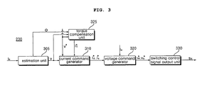
- FIG. 3 is a block diagram illustrating internal constituent elements of a controller shown in FIG. 2 .
- the controller 230 may further include an estimation unit 305, a current command generator 310, a voltage command generator 320, a torque compensation unit 325, and a switching control signal output unit 330.
- the controller 230 may further include an axis converter for converting a three-phase output current (i o ) into a d-axis or q-axis current or converting the d-axis or q-axis current into a three-phase output current (i o ).
- the estimation unit 305 estimates a speed (v) of the motor on the basis of the detected output current (i o ). For example, a mechanical equation of the motor 250 is compared with an electrical equation, such that the estimation unit 305 can estimate the speed (v) of the motor.
- the estimation unit 305 may also estimate the position of the rotor on the basis of the detected output current (i o ).
- the estimation unit 305 can estimate an electrical or mechanical angle of the motor 250 through the rotor position.
- the relationship between the mechanical angle and the electrical angle is represented by the following Equation 1.
- ⁇ Me Number of Poles 2 ⁇ ⁇ e
- the current command generator 310 generates current command values (i*d and i*q) on the basis of the estimated speed (v) and the speed command value (v*). For example, the current command generator 310 performs Proportional Integral (PI) control on the basis of a difference between the estimated speed (v) and the speed command value (v*), such that it can generate the current command values (i*d and i*q).
- the current command generator 310 may include a PI controller (not shown). Also, the current command generator 310 may further include a limiter (not shown) preventing a level of each current command value (i*d or i*q) from exceeding an allowed range.
- the voltage command generator 320 generates voltage command values (v*d and v*q) on the basis of the detected output current (i o ) and the calculated current command values (i*d and i*q). For example, the voltage command generator 320 performs PI control on the basis of a difference between the detected output current (io) and the calculated current command values (i*d and i*q), such that it can generate the voltage command values (v*d and v*q).
- the voltage command generator 320 may include a PI controller (not shown). Also, the voltage command generator 320 may further include a limiter (not shown) for allowing a level of each voltage command value (v*d or v*q) not to exceed an allowed range.
- the torque compensation unit 325 sequentially detects a first mechanical angle ( ⁇ Me1 ) and a second mechanical angle ( ⁇ Me2 ) in response to a speed command or a reference speed spaced apart from the speed command by a predetermined range, and calculates a maximum speed mechanical angle ( ⁇ M ) in response to the detected first and second mechanical angles.
- the controller 230 selects an optimum load pattern table causing a minimal speed ripple from among several load torque patterns in response to the maximum speed mechanical angle.
- the torque compensation unit 325 compares the first mechanical angle ( ⁇ Me1 ) with the second mechanical angle ( ⁇ Me2 ). If the first mechanical angle ( ⁇ Me1 ) is higher than the second mechanical angle ( ⁇ Me2 ) the torque compensation unit 325 may compensate for at least one of the first or second mechanical angles ( ⁇ Me1 and ⁇ Me2 ), and may also calculate a maximum speed mechanical angle ( ⁇ M ) corresponding to the maximum speed ripple on the basis of the compensated mechanical angle. As stated above, the torque compensation unit 325 determines whether an abnormal state occurs in a plurality of mechanical angles sequentially calculated during the constant speed operation, and corrects the abnormal state, such that it can correctly calculate a maximum speed mechanical angle ( ⁇ M ) during the constant speed operation.
- the torque compensation unit 325 generates a compensation current command value (i*c) in response to the calculated maximum speed mechanical angle ( ⁇ M ), such that it can compensate for the speed ripple caused by load torque during the constant speed operation.
- the compensation current command value (i*c) at the calculated maximum speed mechanical angle ( ⁇ M ) may correspond to a minimum value.
- the current command generator 310 adds the current command values (i*d and i*q) to the aforementioned compensation current command value (i*c) so as to generate a final current command value, and outputs the final current command value.
- the current command for compensating for load torque is changed, such that the voltage commands (v*d and v*q) and the output signal (Sic) of the switching control signal output unit 330 are changed.
- a predetermined pattern can be correctly applied to load torque compensation, and the speed ripple caused by the load torque during the constant speed operation can be simply and greatly reduced.
- the switching control signal output unit 330 generates a PWM switching control signal (Sic) for the inverter 220 on the basis of the voltage command values (v*d and v*q), and outputs the PWM switching control signal (Sic) to the inverter 220. Therefore, the switching elements (Sa, S'a, Sb, S'b, Sc, S'c) contained in the inverter 220 perform the on/off switching operation.
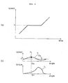
- FIGS. 4(a) and 4(b) are graphs illustrating load torque varying with a motor speed.
- FIG. 4(a) shows the rotating speed of the motor 250.
- the rotating speed of the motor 250 may be gradually increased up to a predetermined rotating speed, and the predetermined rotating speed may be maintained at a specific halt frequency for a predetermined period of time. After the lapse of the predetermined period of time, the rotating speed of the motor 250 may be increased again on the basis of the predetermined rotating speed.
- the halt frequency may be 35 Hz.
- the controller 230 upon receiving a predetermined speed command at the halt frequency, sequentially detects the first and second mechanical angles in response to a speed command or a reference speed spaced apart from the speed command by a predetermined range, and correctly detects the first and second mechanical angles as described above.
- FIG. 4(b) shows the speed ripple generated when the motor 250 is driven in response to a predetermined speed command.
- the speed ripple curve shows the speed estimation value (v*1) estimated by the aforementioned estimation unit 305, and may be shown as a periodic curve such as a sine wave in response to the mechanical angle ( ⁇ Me ) of 360°.
- the load of the motor 250 may be represented by a load torque (TL) according to one period of suction and discharge.
- a maximum speed mechanical angle ( ⁇ M ) is a mechanical angle corresponding to a specific point ( ⁇ 1P ) where the speed estimation value (v*1) reaches a maximum speed estimation value.
- a variety of methods for calculating the maximum speed mechanical angle ( ⁇ M ) may be employed.
- the maximum speed mechanical angle ( ⁇ M ) may be calculated using not only two reference speeds that are spaced apart from the speed command (v1) by a predetermined range, but also the proportional relationship of the two reference speeds.
- the maximum speed mechanical angle ( ⁇ M ) may be calculated not only using the speed command (v1) or one reference speed spaced apart from the speed command (v1) by a predetermined range, but also using the proportional relationship (i.e., an average value of the maximum speed mechanical angle ( ⁇ M ) and one reference speed).
- the embodiment of the present invention has exemplarily described that the maximum speed mechanical angle ( ⁇ M ) is calculated using the average value, the scope or spirit of the present invention is not limited only thereto and can also be applied to other examples as necessary.
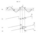
- FIGS. 5(a) to 5(d) are graphs illustrating properties of the embodiments of the present invention.
- FIG. 5(a) shows a speed curve in response to the mechanical angle of FIG. 4(b) . That is, FIG. 5(a) shows a method for calculating the maximum speed mechanical angle ( ⁇ M ) using the speed command (v1) and one reference speed (vr1) spaced apart from the speed command (v1) by a predetermined range.
- P1 and P2 denote predetermined positions that are matched to the reference speed (vr1) on the estimation speed (v1) curve.
- Pa is a predetermined position matched to a first reference speed (vr1)
- Pb is a predetermined position matched to a second reference speed (vr2).
- FIG. 5 (b) shows first and second mechanical angles ( ⁇ a1 and ⁇ a2 ) at P1 and P2 indicating positions matched to reference speeds spaced apart from the speed command by a predetermined range.
- the maximum speed mechanical angle ( ⁇ M ) is an average value of the first and second mechanical angles ( ⁇ a1 and ⁇ a2 ).
- FIG. 5(c) shows first and second mechanical angles ( ⁇ b1 and ⁇ b2 ) at P1 and P2 indicating positions matched to reference speeds spaced apart from the speed command by a predetermined range.
- the first mechanical angle ( ⁇ b1 ) is higher than the second mechanical angle ( ⁇ b2 ).
- ⁇ b1 is greater than ⁇ b2 for the following reason.
- the mechanical angle period is repeated between contact points to the corresponding reference speed (vr1).
- vr1 the maximum speed mechanical angle
- the first mechanical angle ( ⁇ b1 ) is compensated for.
- Equation 3 the maximum speed mechanical angle ( ⁇ M ) can be represented by the following Equation 3.
- ⁇ M ⁇ b ⁇ 1 - 360 ⁇ ° + ⁇ b ⁇ 2 2
- Equation 3 the maximum speed mechanical angle ( ⁇ M ) is identical to an average of one value of ( ⁇ b1 - 360°) and the second mechanical angle ( ⁇ a2 ).
- FIG. 5 (d) shows first and second mechanical angles ( ⁇ c1 and ⁇ c2 ) at P1 and P2 indicating positions matched to reference speeds spaced apart from the speed command by a predetermined range.
- the first mechanical angle ( ⁇ b1 ) is higher than the second mechanical angle ( ⁇ b2 ).
- the reason of ⁇ b1 is greater than ⁇ b2 for the following reason.
- the mechanical angle period is repeated between contact points to the corresponding reference speed (vr1).
- vr1 the maximum speed mechanical angle
- the second mechanical angle ( ⁇ bc2 ) is compensated for.
- Equation 4 the maximum speed mechanical angle ( ⁇ M ) can be represented by the following Equation 4.
- ⁇ M ⁇ c ⁇ 1 + ⁇ c ⁇ 2 + 360 ⁇ ° 2
- Equation 4 the maximum speed mechanical angle ( ⁇ M ) is identical to an average of the first mechanical angle ( ⁇ c1 ) and one value of ( ⁇ c2 + 360°).
- At least one of the detected first or second mechanical angles is compensated for such that a maximum speed mechanical angle during the constant speed operation can be correctly calculated.
- FIG. 6 is a flowchart illustrating a method for driving a motor according to an embodiment of the present invention.
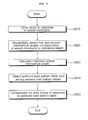
- FIGS. 7 and 8 are graphs illustrating the motor driving method shown in FIG. 6 .
- the controller 230 drives the motor 250 in response to the speed command (v*) at step S610.
- the controller 230 may control the motor 250 to be driven by a specific speed command corresponding to a halt frequency (about 35 Hz). Therefore, the controller 250 outputs the corresponding inverter switching control signal (Sic) to the inverter 220.
- the controller 230 sequentially detects first and second mechanical angles in response to a speed command and a reference speed spaced apart from the speed command by a predetermined range at step S620.
- the controller 230 recognizes the reference speed (vr1) spaced apart from the speed command (v*1) by a predetermined range as shown in FIG. 5 , and detects the first and second mechanical angles at P1 and P2 corresponding to the reference speed (vr1). Such detection of the first and second mechanical angles may be carried out in the estimation unit 305 and the torque compensation unit 325.
- the controller 230 calculates a maximum speed mechanical angle ( ⁇ M ) at step S630.
- the maximum speed mechanical angle ( ⁇ M ) may be calculated as an average of the first and second mechanical angles as necessary.
- the controller 230 may select an optimum load pattern table causing a minimal speed ripple from among a plurality of load torque patterns at step S640.
- the controller 230 especially, the torque compensation unit 325, selects a maximum speed mechanical angle ( ⁇ M ) having a minimal value from among several load torque patterns, matches the selected maximum speed mechanical angle ( ⁇ M ) to a minimum value from among the corresponding predetermined load torque patterns, and outputs a compensation current command value (i*c) in response to the corresponding load torque pattern. Therefore, the current command generator 310 adds the output current command values (i*d and i*q) and the aforementioned compensation current command value (i*c), and generates/outputs the final current command value.
- the current command for compensating for the load torque is changed, such that the voltage commands (v*d and v*q) and the output (sic) of the switching control signal output unit are changed.
- switching control signals for individual load torque patterns are output to drive the motor 250, the speed of the motor 250 is estimated, and the load torque pattern causing a minimal ripple is selected.
- FIG. 7 shows a plurality of load patterns, i.e., load patterns A, B and C, however the scope and types of such load patterns of the present invention are not limited only thereto, and a variety of load patterns may be predetermined as necessary.
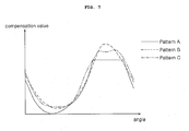
- FIG. 8 shows the speed estimated by the estimation unit 305 in response to the load patterns of FIG. 7 , and also shows individual speed ripples.
- FIG. 8(a) shows the speed ripple (R va ) in response to the load pattern A
- FIG. 8(b) shows the speed ripple (R vb ) in response to the load pattern B
- FIG. 8(c) shows the speed ripple (R vc ) in response to the load pattern C.
- the controller 230 compensates for the load torque in response to the selected load pattern table at step S650.
- the controller 230 outputs the compensation current command value (i*c). Therefore, the current command generator 310 adds the output command values (i*d and i*q) and the aforementioned compensation current command value (i*c), and generates the final current command value using the added result.
- the current command for compensating for load torque is changed, such that the voltage commands (v*d and v*q) and the output (Sic) of the switching control signal output unit 330 are changed.
- one step for correcting the detected first and second mechanical angles may be further inserted between the step S620 and the step S630 as necessary.
- the controller 230 can compensate for either one of the first and second mechanical angles.
- the controller 230 can calculate a maximum speed mechanical angle ( ⁇ M ) on the basis of the compensated first and second mechanical angles.
- the controller 230 can compensate for the first mechanical angle ( ⁇ 1 ). That is, the controller 230 subtracts 360° from the first mechanical angle. Therefore, as shown in Equation 3, an average of the compensated first and second mechanical angles is determined to be a maximum speed mechanical angle.
- the controller 230 can compensate for the second mechanical angle ( ⁇ 2 ). That is, the controller 230 adds 360° to the second mechanical angle. Therefore, as shown in Equation 4, an average of the compensated first and second mechanical angles is determined to be a maximum speed mechanical angle.
- controller 230 may further include another step for determining whether the motor is stably driven.
- the controller 230 before calculating the first and second mechanical angles, determines mechanical angles at Pa and Pb corresponding to different reference speeds (vr1 and vr2). If the range of the mechanical angles is within an allowed range, the controller 230 may determine stable speed. Otherwise, before calculating the first and second mechanical angles, the controller 230 estimates the speed ripple, and analyzes components of the corresponding speed ripple. In this case, if the range of the analyzed mechanical angles is not within the allowed range, the controller 230 may determine unstable speed as necessary.
- FIG. 9 is a flowchart illustrating a method for driving a motor of an air conditioner according to another embodiment of the present invention.
- the controller 230 controls the motor 250 to be driven in response to the speed command (v*) at step S910.
- the controller 230 controls the motor 250 to be driven by a command of a predetermined speed corresponding to a halt frequency (about 35 Hz). Therefore, the controller 230 outputs the corresponding inverter switching control signal (Sic) to the inverter 220.
- the controller 230 sequentially detects the first and second mechanical angles in response to a speed command or a reference speed spaced apart from the speed command by a predetermined range at step S1020. As shown in FIG. 5 , by means of the reference speed (vr1) spaced apart from the speed command (v*1) by a predetermined range, the controller 230 detects first and second mechanical angles at P1 and P2 corresponding to the reference speed (vr1). Such detection of the first and second mechanical angles may be carried out by the estimation unit 305 and the torque compensation unit 325.
- the controller 230 determines whether the first mechanical angle is higher than the second mechanical angle at step S930. If the second mechanical angle is higher than the first mechanical angle, this means a normal state, such that the controller 230 can calculate a maximum speed mechanical angle using an average of the first and second mechanical angles.
- the controller 230 calculates the maximum speed mechanical angle ( ⁇ M ) on the basis of the compensated first and second mechanical angles.
- the controller 230 In response to the calculated maximum speed mechanical angle ( ⁇ M ), the controller 230 (especially, the torque compensation unit 325) performs the corresponding load torque compensation.
- the calculated maximum speed mechanical angle ( ⁇ M ) is matched to a minimum value from among the predetermined load torque patterns, and the controller 230 may output the compensation current command value (i*c) in response to the corresponding load torque pattern.
- the speed ripple caused by specific load can be effectively removed.
- the controller 230 may further include a step for determining whether the motor is stably driven.
- the controller 230 determines mechanical angles at Pa and Pb corresponding to different reference speeds (vr1 and vr2). If the range of the determined mechanical angles is within the allowed range, the controller 230 may determine stable speed. Otherwise, before calculating the first and second mechanical angles, the controller 230 estimates the speed ripple, and analyzes components of the corresponding speed ripple. In this case, if the range of the analyzed mechanical angles is not within the allowed range, the controller 230 may determine unstable speed as necessary.
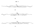
- FIG. 10 is a flowchart illustrating a method for calculating a maximum speed mechanical angle shown in FIG. 9 .
- a maximum speed mechanical angle can be calculated using steps of FIG. 10 .
- the controller 230 determines whether a difference value between the first mechanical angle and the angle of 360° is less than the second mechanical angle (i.e.,
- the controller 230 calculates an average of the compensated first and second mechanical angles as a maximum speed mechanical angle at step S1030.
- the controller 230 determines whether a difference value between the first mechanical angle and the angle of 360° is higher than the second mechanical angle (i.e.,
- Equation 4 the average of the compensated first and second mechanical angles is calculated as the maximum speed mechanical angle at step S1030.
- FIG. 11 is a flowchart illustrating a method for driving a motor of an air conditioner according to another embodiment of the present invention.
- FIGS. 12 and 13 show the driving method shown in FIG. 11 .
- the controller 230 controls the motor 250 to be driven in response to the speed command (v*) at step S1110.
- the controller 230 controls the motor 250 to be driven by a command of a predetermined speed corresponding to a halt frequency (about 35 Hz). Therefore, the controller 230 outputs the corresponding inverter switching control signal (Sic) to the inverter 220.
- the controller 230 sequentially detects the first and second mechanical angles in response to a speed command or a reference speed spaced apart from the speed command by a predetermined range at step S1120. As shown in FIG. 5 , by means of the reference speed (vr1) spaced apart from the speed command (v*1) by a predetermined range, the controller 230 detects first and second mechanical angles at P1 and P2 corresponding to the reference speed (vr1). Such detection of the first and second mechanical angles may be carried out by the estimation unit 305 and the torque compensation unit 325.
- the controller 230 calculates the maximum speed mechanical angle ( ⁇ M ) at step S1130.
- the maximum speed mechanical angle ( ⁇ M ) can be calculated as an average of the first and second mechanical angles.
- the controller 230 calculates the pattern matching angle in response to the calculated maximum speed mechanical angle ( ⁇ M ) at step S1140.
- the controller 230 (especially, the torque compensation unit 325), using the maximum speed mechanical angle ( ⁇ M ) and the predetermined matching angle ( ⁇ dm ), calculates a pattern matching compensation angle ( ⁇ c ) causing a minimal speed ripple, and calculates the final pattern matching compensation angle ( ⁇ fm ) in response to the predetermined pattern matching angle ( ⁇ dm ) and the pattern matching compensation angle ( ⁇ c ).
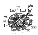
- FIG. 12 is a view illustrating the internal configuration of a three-phase motor.
- a stator coil 710 and a rotor magnet 720 are shown in FIG. 12 .
- the motor shown in FIG. 12 is a three-phase motor having 6 poles, and the region of the motor is divided into a first area (u1, v1, w1), a second area (u2, v2, w2), and a third area (u3, v3, w3).
- the maximum speed mechanical angle ( ⁇ M ) may be arranged in three areas of the electrical angle.
- FIG. 13 shows three areas of the electrical angle.
- the calculated maximum speed mechanical angle ( ⁇ aM ) is arranged in the first area (u1, v1, w1) the corresponding electrical angle may be arranged in different areas as shown in FIGS. 13(a), 13(b), and 13(c) .
- first to third cases such as FIGS. 13(a), 13(b) and 13(c) .
- individual predetermined matching angles are established, and a pattern matching compensation angle causing a minimal speed ripple is calculated.
- a predetermined matching angle may be set to (240° + B).
- a compensation value is changed within the predetermined range from the predetermined matching angle (240°+ B), such that the speed ripple is calculated using the changed compensation value.
- the compensation value causing the minimal speed ripple is calculated as the pattern matching compensation angle ( ⁇ ).
- the final pattern matching angle may be set to (240°+ B + ⁇ ).
- a predetermined matching angle may be set to (120°+ B).
- a compensation value is changed within the predetermined range from the predetermined matching angle (120°+ B), such that the speed ripple is calculated using the changed compensation value.
- the compensation value causing the minimal speed ripple is calculated as the pattern matching compensation angle ( ⁇ ).
- the final pattern matching angle may be set to (120°+ B + ⁇ ).
- a predetermined matching angle may be set to (B).
- a compensation value is changed within the predetermined range from the predetermined matching angle (B), such that the speed ripple is calculated using the changed compensation value.
- the compensation value causing the minimal speed ripple is calculated as the pattern matching compensation angle ( ⁇ ).
- the final pattern matching angle may be set to (B + ⁇ ).
- the controller 230 compensates for load torque using a load pattern in response to the calculated pattern matching angle at step S1150.
- the controller 230 (especially, the torque compensation unit 325) performs matching of a predetermined load torque pattern in response to the calculated pattern matching angle, and outputs the compensation current command value (i*c) in response to the corresponding load torque pattern. Therefore, the current command generator 310 adds the output current command values (i*d and i*q) and the aforementioned compensation current command value (i*c), generates the final current command value, and outputs it. Therefore, a current command for compensating for load torque is changed, such that the voltage commands (v*d and v*q) and the output signal (Sic) of the switching control signal output unit are changed.
- the controller 230 calculates the pattern matching angle in response to the calculated maximum speed mechanical angle during the constant speed operation, such that it can decrease the speed ripple. Especially, the controller 230 calculates the pattern matching compensation angle causing a minimal speed ripple using the predetermined matching angle, such that it can greatly reduce the speed ripple. In addition, if the speed ripple is increased by an assembly error between the compressor and the motor, the controller 230 can greatly reduce the speed ripple using the pattern matching compensation angle.
- step S1120 may be inserted between the step S1120 and the step S1130, such that the controller 230 may further perform the aforementioned step.
- the controller 230 calculates the maximum speed mechanical angle using an average of the first and second mechanical angles.
- the controller 230 can compensate for either one of the first and second mechanical angles.
- the controller 230 can calculate a maximum speed mechanical angle ( ⁇ M ) on the basis of the compensated first and second mechanical angles.
- the controller 230 may compensate for the first mechanical angle ( ⁇ 1 ). That is, the controller 230 subtracts 360° from the first mechanical angle ( ⁇ 1 ). Therefore, as shown in Equation 3, an average of the compensated first and second mechanical angles can be calculated as a maximum speed mechanical angle.
- the controller 230 may compensate for the second mechanical angle ( ⁇ 2 ). That is, the controller 230 adds 360° to the second mechanical angle ( ⁇ 2 ). Accordingly, as shown in Equation 4, an average of the compensated first and second mechanical angles may be calculated as a maximum speed mechanical angle.
- the controller 230 may further include a step for determining whether the motor is stably driven as necessary.
- the controller 230 determines mechanical angles at Pa and Pb corresponding to different reference speeds (vr1 and vr2). If the range of the mechanical angles is within an allowed range, the controller 230 may determine stable speed. Otherwise, before calculating the first and second mechanical angles, the controller 230 estimates the speed ripple, and analyzes components of the corresponding speed ripple. If the analyzed result is not within the allowed range, the controller 230 may determine unstable speed as necessary.
- the apparatus or method for driving the motor of the air conditioner according to the present invention performs matching of a load pattern table in response to a maximum speed mechanical angle calculated during the constant speed operation, such that it can calculate an optimum load pattern table causing a minimum speed ripple from among a plurality of load pattern tables.
- the motor driving apparatus or method according to the present invention can simply and greatly decrease the speed ripple caused by load torque during the constant speed operation.
- the motor driving apparatus or method according to the present invention determines whether an abnormal state occurs in a plurality of sequentially calculated mechanical angles, and corrects the abnormal state, such that a maximum speed mechanical angle can be correctly calculated during the constant speed operation.
- the apparatus or method for driving the motor of the air conditioner according to the embodiment of the present invention can determine whether an abnormal state occurs in a plurality of mechanical angles sequentially calculated during the constant speed operation, and corrects the abnormal state, such that a maximum speed mechanical angle can be correctly calculated during the constant speed operation.
- the apparatus or method for driving the motor of the air conditioner according to the embodiment of the present invention calculates a pattern matching angle in response to the maximum speed mechanical angle calculated during the constant speed operation, resulting in reduction of the speed ripple.
- the apparatus or method for driving the motor of the air conditioner calculates a pattern matching compensation angle having a minimum speed ripple using a predetermined matching angle, resulting in reduction of the speed ripple.
- the apparatus or method for driving the motor of the air conditioner according to the embodiment of the present invention uses a pattern matching compensation angle although the speed ripple is increased owing to an assembly error between the compressor and the motor, such that it can greatly decrease the speed ripple.
Landscapes
- Engineering & Computer Science (AREA)
- Power Engineering (AREA)
- Control Of Motors That Do Not Use Commutators (AREA)
- Control Of Ac Motors In General (AREA)
- Air Conditioning Control Device (AREA)
Applications Claiming Priority (3)
| Application Number | Priority Date | Filing Date | Title |
|---|---|---|---|
| KR1020090072863A KR101634640B1 (ko) | 2009-08-07 | 2009-08-07 | 공기조화기의 전동기 구동장치 및 그 구동방법 |
| KR1020090072864A KR101687549B1 (ko) | 2009-08-07 | 2009-08-07 | 공기조화기의 전동기 구동장치 및 그 구동방법 |
| KR1020090072865A KR20110015244A (ko) | 2009-08-07 | 2009-08-07 | 공기조화기의 전동기 구동장치 및 그 구동방법 |
Publications (3)
| Publication Number | Publication Date |
|---|---|
| EP2296263A2 true EP2296263A2 (fr) | 2011-03-16 |
| EP2296263A3 EP2296263A3 (fr) | 2017-07-19 |
| EP2296263B1 EP2296263B1 (fr) | 2018-12-12 |
Family
ID=43502946
Family Applications (1)
| Application Number | Title | Priority Date | Filing Date |
|---|---|---|---|
| EP10008242.9A Not-in-force EP2296263B1 (fr) | 2009-08-07 | 2010-08-06 | Appareil pour commande de moteur d'un climatiseur et son procédé de commande |
Country Status (3)
| Country | Link |
|---|---|
| US (1) | US8269438B2 (fr) |
| EP (1) | EP2296263B1 (fr) |
| CN (1) | CN101997479B (fr) |
Families Citing this family (15)
| Publication number | Priority date | Publication date | Assignee | Title |
|---|---|---|---|---|
| US8853979B2 (en) * | 2011-02-28 | 2014-10-07 | Deere & Company | Method and system for calibrating rotor position offset of an electric motor |
| KR101288196B1 (ko) * | 2011-09-09 | 2013-07-19 | 삼성전기주식회사 | 초기 보정 기능을 갖는 모터 구동 장치 및 방법 |
| JP5916342B2 (ja) * | 2011-10-21 | 2016-05-11 | 三菱重工業株式会社 | モータ制御装置、モータ制御方法 |
| JP5693429B2 (ja) * | 2011-10-21 | 2015-04-01 | 三菱重工業株式会社 | モータ制御装置、モータ制御方法 |
| JP5916343B2 (ja) * | 2011-10-21 | 2016-05-11 | 三菱重工業株式会社 | モータ制御装置、モータ制御方法 |
| KR101772083B1 (ko) | 2012-01-30 | 2017-08-28 | 엘지전자 주식회사 | 압축기 제어 장치 및 이를 포함한 냉장고 |
| KR101382749B1 (ko) * | 2012-04-13 | 2014-04-08 | 현대자동차주식회사 | 레졸버 옵셋 보정 방법 |
| US8775003B2 (en) * | 2012-11-28 | 2014-07-08 | GM Global Technology Operations LLC | Methods and systems for controlling a proportional integrator |
| JP2016189668A (ja) * | 2015-03-30 | 2016-11-04 | Juki株式会社 | モータ制御装置、モータ制御方法、ミシン及びそのプログラム |
| JP6364463B2 (ja) * | 2016-09-26 | 2018-07-25 | 日立ジョンソンコントロールズ空調株式会社 | モータ駆動装置、及びこれを備える冷凍サイクル装置、並びにモータ駆動方法 |
| CN108023511B (zh) * | 2016-10-28 | 2020-10-02 | 沈阳高精数控智能技术股份有限公司 | 砂带磨床恒力磨削控制系统中砂带轮收放卷的控制方法 |
| DK179621B1 (en) * | 2017-03-09 | 2019-03-01 | OJ Electronics A/S | HASTIGHEDSRIPPLE COMPENSATION |
| CN112994571B (zh) * | 2019-12-17 | 2023-03-14 | 广东美芝制冷设备有限公司 | 压缩机及其控制方法、转矩补偿方法、装置以及存储介质 |
| CN114517937B (zh) * | 2022-03-03 | 2023-08-01 | 海信空调有限公司 | 空调器和抑制压缩机低频振动的方法 |
| US12549122B2 (en) * | 2023-03-31 | 2026-02-10 | Texas Instruments Incorporated | Motor controller with adaptive reference load angle for improving power efficiency |
Family Cites Families (7)
| Publication number | Priority date | Publication date | Assignee | Title |
|---|---|---|---|---|
| JPH069439B2 (ja) * | 1984-06-18 | 1994-02-02 | 株式会社日立製作所 | 電動機のトルク制御装置 |
| JPH06106036B2 (ja) * | 1986-12-27 | 1994-12-21 | 株式会社日立製作所 | 電動機の速度制御装置 |
| JPH03216299A (ja) * | 1990-01-22 | 1991-09-24 | Aida Eng Ltd | ダイハイトの自動調整装置 |
| US5319294A (en) * | 1992-05-28 | 1994-06-07 | Matsushita Electric Industrial Co., Ltd. | Apparatus for automatically adjusting offset correction values for current detectors |
| US7218072B2 (en) * | 2003-02-18 | 2007-05-15 | Matsushita Electric Industrial Co., Ltd. | Motor driving device, motor to be driven by the same device, and apparatus using the same motor |
| EP1777806A2 (fr) * | 2005-10-21 | 2007-04-25 | NSK Ltd. | Dispositif de commande d'un moteur électrique et de direction assistée électrique |
| JP5130716B2 (ja) * | 2007-01-09 | 2013-01-30 | 株式会社ジェイテクト | モータ制御装置および電気式動力舵取装置 |
-
2010
- 2010-08-05 US US12/851,019 patent/US8269438B2/en active Active
- 2010-08-06 EP EP10008242.9A patent/EP2296263B1/fr not_active Not-in-force
- 2010-08-09 CN CN2010102510388A patent/CN101997479B/zh not_active Expired - Fee Related
Non-Patent Citations (1)
| Title |
|---|
| None |
Also Published As
| Publication number | Publication date |
|---|---|
| CN101997479B (zh) | 2013-01-30 |
| CN101997479A (zh) | 2011-03-30 |
| EP2296263B1 (fr) | 2018-12-12 |
| US8269438B2 (en) | 2012-09-18 |
| EP2296263A3 (fr) | 2017-07-19 |
| US20110031912A1 (en) | 2011-02-10 |
Similar Documents
| Publication | Publication Date | Title |
|---|---|---|
| EP2296263B1 (fr) | Appareil pour commande de moteur d'un climatiseur et son procédé de commande | |
| EP2355333B1 (fr) | Appareil pour commander une compression de climatiseur et son procédé | |
| EP2063194A1 (fr) | Contrôleur de moteur d'un climatiseur | |
| EP2448110A2 (fr) | Appareil de réfrigération et contrôleur pour moteur synchrone à aimant permanent | |
| KR101561922B1 (ko) | 공기조화기의 전동기 제어방법 | |
| KR101694539B1 (ko) | 공기 조화기의 압축기 구동장치 및 그 구동방법 | |
| US20240405694A1 (en) | Power converting apparatus, motor drive unit, and refrigeration cycle-incorporating device | |
| JP2004364492A (ja) | モータ駆動装置及び空気調和装置 | |
| KR101770425B1 (ko) | 냉장고 및 냉장고의 제어방법 | |
| JP2010098854A (ja) | モータの制御装置とそれを用いた冷凍装置および空調装置 | |
| WO2009064050A2 (fr) | Commande moteur d'un climatiseur | |
| KR101054438B1 (ko) | 공기조화기의 전동기 구동장치 | |
| KR101634640B1 (ko) | 공기조화기의 전동기 구동장치 및 그 구동방법 | |
| JP2012165582A (ja) | モータ制御装置 | |
| KR102010388B1 (ko) | 모터 구동장치 및 이를 구비하는 공기조화기 | |
| JP2006136167A (ja) | 電力変換装置、電力変換装置の制御方法及び空気調和装置 | |
| KR20110081594A (ko) | 공기조화기의 전동기 구동장치 | |
| KR101049930B1 (ko) | 공기조화기의 전동기 구동장치 | |
| KR20100133635A (ko) | 공기조화기의 전동기 구동장치 | |
| KR101687549B1 (ko) | 공기조화기의 전동기 구동장치 및 그 구동방법 | |
| JP2010288348A (ja) | 同期モータの制御装置とそれを用いた冷凍装置および空調装置 | |
| JP2009131001A (ja) | モータ駆動用インバータ制御装置 | |
| KR20110015244A (ko) | 공기조화기의 전동기 구동장치 및 그 구동방법 | |
| KR101990445B1 (ko) | 전력변환장치 및 이를 구비하는 공기조화기 | |
| KR102080519B1 (ko) | 모터 구동장치 및 이를 구비하는 공기조화기 |
Legal Events
| Date | Code | Title | Description |
|---|---|---|---|
| PUAI | Public reference made under article 153(3) epc to a published international application that has entered the european phase |
Free format text: ORIGINAL CODE: 0009012 |
|
| AK | Designated contracting states |
Kind code of ref document: A2 Designated state(s): AL AT BE BG CH CY CZ DE DK EE ES FI FR GB GR HR HU IE IS IT LI LT LU LV MC MK MT NL NO PL PT RO SE SI SK SM TR |
|
| AX | Request for extension of the european patent |
Extension state: BA ME RS |
|
| PUAL | Search report despatched |
Free format text: ORIGINAL CODE: 0009013 |
|
| AK | Designated contracting states |
Kind code of ref document: A3 Designated state(s): AL AT BE BG CH CY CZ DE DK EE ES FI FR GB GR HR HU IE IS IT LI LT LU LV MC MK MT NL NO PL PT RO SE SI SK SM TR |
|
| AX | Request for extension of the european patent |
Extension state: BA ME RS |
|
| RIC1 | Information provided on ipc code assigned before grant |
Ipc: F25B 49/02 20060101ALN20170609BHEP Ipc: H02P 6/10 20060101AFI20170609BHEP Ipc: H02P 25/00 20060101ALI20170609BHEP |
|
| STAA | Information on the status of an ep patent application or granted ep patent |
Free format text: STATUS: REQUEST FOR EXAMINATION WAS MADE |
|
| 17P | Request for examination filed |
Effective date: 20171214 |
|
| RBV | Designated contracting states (corrected) |
Designated state(s): AL AT BE BG CH CY CZ DE DK EE ES FI FR GB GR HR HU IE IS IT LI LT LU LV MC MK MT NL NO PL PT RO SE SI SK SM TR |
|
| GRAP | Despatch of communication of intention to grant a patent |
Free format text: ORIGINAL CODE: EPIDOSNIGR1 |
|
| STAA | Information on the status of an ep patent application or granted ep patent |
Free format text: STATUS: GRANT OF PATENT IS INTENDED |
|
| RIC1 | Information provided on ipc code assigned before grant |
Ipc: F25B 49/02 20060101ALN20180518BHEP Ipc: H02P 6/10 20060101AFI20180518BHEP Ipc: H02P 25/00 20060101ALI20180518BHEP |
|
| INTG | Intention to grant announced |
Effective date: 20180620 |
|
| RAP1 | Party data changed (applicant data changed or rights of an application transferred) |
Owner name: LG ELECTRONICS INC. |
|
| GRAJ | Information related to disapproval of communication of intention to grant by the applicant or resumption of examination proceedings by the epo deleted |
Free format text: ORIGINAL CODE: EPIDOSDIGR1 |
|
| STAA | Information on the status of an ep patent application or granted ep patent |
Free format text: STATUS: REQUEST FOR EXAMINATION WAS MADE |
|
| GRAR | Information related to intention to grant a patent recorded |
Free format text: ORIGINAL CODE: EPIDOSNIGR71 |
|
| GRAS | Grant fee paid |
Free format text: ORIGINAL CODE: EPIDOSNIGR3 |
|
| STAA | Information on the status of an ep patent application or granted ep patent |
Free format text: STATUS: GRANT OF PATENT IS INTENDED |
|
| GRAA | (expected) grant |
Free format text: ORIGINAL CODE: 0009210 |
|
| STAA | Information on the status of an ep patent application or granted ep patent |
Free format text: STATUS: THE PATENT HAS BEEN GRANTED |
|
| INTC | Intention to grant announced (deleted) | ||
| RIC1 | Information provided on ipc code assigned before grant |
Ipc: H02P 25/00 20060101ALI20181025BHEP Ipc: F25B 49/02 20060101ALN20181025BHEP Ipc: H02P 6/10 20060101AFI20181025BHEP |
|
| INTG | Intention to grant announced |
Effective date: 20181030 |
|
| AK | Designated contracting states |
Kind code of ref document: B1 Designated state(s): AL AT BE BG CH CY CZ DE DK EE ES FI FR GB GR HR HU IE IS IT LI LT LU LV MC MK MT NL NO PL PT RO SE SI SK SM TR |
|
| REG | Reference to a national code |
Ref country code: GB Ref legal event code: FG4D |
|
| REG | Reference to a national code |
Ref country code: CH Ref legal event code: EP |
|
| REG | Reference to a national code |
Ref country code: AT Ref legal event code: REF Ref document number: 1077306 Country of ref document: AT Kind code of ref document: T Effective date: 20181215 |
|
| REG | Reference to a national code |
Ref country code: DE Ref legal event code: R096 Ref document number: 602010055724 Country of ref document: DE |
|
| REG | Reference to a national code |
Ref country code: IE Ref legal event code: FG4D |
|
| REG | Reference to a national code |
Ref country code: NL Ref legal event code: MP Effective date: 20181212 |
|
| REG | Reference to a national code |
Ref country code: LT Ref legal event code: MG4D |
|
| PG25 | Lapsed in a contracting state [announced via postgrant information from national office to epo] |
Ref country code: BG Free format text: LAPSE BECAUSE OF FAILURE TO SUBMIT A TRANSLATION OF THE DESCRIPTION OR TO PAY THE FEE WITHIN THE PRESCRIBED TIME-LIMIT Effective date: 20190312 Ref country code: ES Free format text: LAPSE BECAUSE OF FAILURE TO SUBMIT A TRANSLATION OF THE DESCRIPTION OR TO PAY THE FEE WITHIN THE PRESCRIBED TIME-LIMIT Effective date: 20181212 Ref country code: NO Free format text: LAPSE BECAUSE OF FAILURE TO SUBMIT A TRANSLATION OF THE DESCRIPTION OR TO PAY THE FEE WITHIN THE PRESCRIBED TIME-LIMIT Effective date: 20190312 Ref country code: LT Free format text: LAPSE BECAUSE OF FAILURE TO SUBMIT A TRANSLATION OF THE DESCRIPTION OR TO PAY THE FEE WITHIN THE PRESCRIBED TIME-LIMIT Effective date: 20181212 Ref country code: LV Free format text: LAPSE BECAUSE OF FAILURE TO SUBMIT A TRANSLATION OF THE DESCRIPTION OR TO PAY THE FEE WITHIN THE PRESCRIBED TIME-LIMIT Effective date: 20181212 Ref country code: HR Free format text: LAPSE BECAUSE OF FAILURE TO SUBMIT A TRANSLATION OF THE DESCRIPTION OR TO PAY THE FEE WITHIN THE PRESCRIBED TIME-LIMIT Effective date: 20181212 Ref country code: FI Free format text: LAPSE BECAUSE OF FAILURE TO SUBMIT A TRANSLATION OF THE DESCRIPTION OR TO PAY THE FEE WITHIN THE PRESCRIBED TIME-LIMIT Effective date: 20181212 |
|
| REG | Reference to a national code |
Ref country code: AT Ref legal event code: MK05 Ref document number: 1077306 Country of ref document: AT Kind code of ref document: T Effective date: 20181212 |
|
| PG25 | Lapsed in a contracting state [announced via postgrant information from national office to epo] |
Ref country code: AL Free format text: LAPSE BECAUSE OF FAILURE TO SUBMIT A TRANSLATION OF THE DESCRIPTION OR TO PAY THE FEE WITHIN THE PRESCRIBED TIME-LIMIT Effective date: 20181212 Ref country code: SE Free format text: LAPSE BECAUSE OF FAILURE TO SUBMIT A TRANSLATION OF THE DESCRIPTION OR TO PAY THE FEE WITHIN THE PRESCRIBED TIME-LIMIT Effective date: 20181212 Ref country code: GR Free format text: LAPSE BECAUSE OF FAILURE TO SUBMIT A TRANSLATION OF THE DESCRIPTION OR TO PAY THE FEE WITHIN THE PRESCRIBED TIME-LIMIT Effective date: 20190313 |
|
| PG25 | Lapsed in a contracting state [announced via postgrant information from national office to epo] |
Ref country code: NL Free format text: LAPSE BECAUSE OF FAILURE TO SUBMIT A TRANSLATION OF THE DESCRIPTION OR TO PAY THE FEE WITHIN THE PRESCRIBED TIME-LIMIT Effective date: 20181212 |
|
| PG25 | Lapsed in a contracting state [announced via postgrant information from national office to epo] |
Ref country code: CZ Free format text: LAPSE BECAUSE OF FAILURE TO SUBMIT A TRANSLATION OF THE DESCRIPTION OR TO PAY THE FEE WITHIN THE PRESCRIBED TIME-LIMIT Effective date: 20181212 Ref country code: IT Free format text: LAPSE BECAUSE OF FAILURE TO SUBMIT A TRANSLATION OF THE DESCRIPTION OR TO PAY THE FEE WITHIN THE PRESCRIBED TIME-LIMIT Effective date: 20181212 Ref country code: PL Free format text: LAPSE BECAUSE OF FAILURE TO SUBMIT A TRANSLATION OF THE DESCRIPTION OR TO PAY THE FEE WITHIN THE PRESCRIBED TIME-LIMIT Effective date: 20181212 Ref country code: PT Free format text: LAPSE BECAUSE OF FAILURE TO SUBMIT A TRANSLATION OF THE DESCRIPTION OR TO PAY THE FEE WITHIN THE PRESCRIBED TIME-LIMIT Effective date: 20190412 |
|
| PG25 | Lapsed in a contracting state [announced via postgrant information from national office to epo] |
Ref country code: EE Free format text: LAPSE BECAUSE OF FAILURE TO SUBMIT A TRANSLATION OF THE DESCRIPTION OR TO PAY THE FEE WITHIN THE PRESCRIBED TIME-LIMIT Effective date: 20181212 Ref country code: SM Free format text: LAPSE BECAUSE OF FAILURE TO SUBMIT A TRANSLATION OF THE DESCRIPTION OR TO PAY THE FEE WITHIN THE PRESCRIBED TIME-LIMIT Effective date: 20181212 Ref country code: RO Free format text: LAPSE BECAUSE OF FAILURE TO SUBMIT A TRANSLATION OF THE DESCRIPTION OR TO PAY THE FEE WITHIN THE PRESCRIBED TIME-LIMIT Effective date: 20181212 Ref country code: IS Free format text: LAPSE BECAUSE OF FAILURE TO SUBMIT A TRANSLATION OF THE DESCRIPTION OR TO PAY THE FEE WITHIN THE PRESCRIBED TIME-LIMIT Effective date: 20190412 Ref country code: SK Free format text: LAPSE BECAUSE OF FAILURE TO SUBMIT A TRANSLATION OF THE DESCRIPTION OR TO PAY THE FEE WITHIN THE PRESCRIBED TIME-LIMIT Effective date: 20181212 |
|
| REG | Reference to a national code |
Ref country code: DE Ref legal event code: R097 Ref document number: 602010055724 Country of ref document: DE |
|
| PLBE | No opposition filed within time limit |
Free format text: ORIGINAL CODE: 0009261 |
|
| STAA | Information on the status of an ep patent application or granted ep patent |
Free format text: STATUS: NO OPPOSITION FILED WITHIN TIME LIMIT |
|
| PG25 | Lapsed in a contracting state [announced via postgrant information from national office to epo] |
Ref country code: DK Free format text: LAPSE BECAUSE OF FAILURE TO SUBMIT A TRANSLATION OF THE DESCRIPTION OR TO PAY THE FEE WITHIN THE PRESCRIBED TIME-LIMIT Effective date: 20181212 Ref country code: AT Free format text: LAPSE BECAUSE OF FAILURE TO SUBMIT A TRANSLATION OF THE DESCRIPTION OR TO PAY THE FEE WITHIN THE PRESCRIBED TIME-LIMIT Effective date: 20181212 Ref country code: SI Free format text: LAPSE BECAUSE OF FAILURE TO SUBMIT A TRANSLATION OF THE DESCRIPTION OR TO PAY THE FEE WITHIN THE PRESCRIBED TIME-LIMIT Effective date: 20181212 |
|
| 26N | No opposition filed |
Effective date: 20190913 |
|
| PG25 | Lapsed in a contracting state [announced via postgrant information from national office to epo] |
Ref country code: TR Free format text: LAPSE BECAUSE OF FAILURE TO SUBMIT A TRANSLATION OF THE DESCRIPTION OR TO PAY THE FEE WITHIN THE PRESCRIBED TIME-LIMIT Effective date: 20181212 |
|
| GBPC | Gb: european patent ceased through non-payment of renewal fee |
Effective date: 20190806 |
|
| PG25 | Lapsed in a contracting state [announced via postgrant information from national office to epo] |
Ref country code: MC Free format text: LAPSE BECAUSE OF FAILURE TO SUBMIT A TRANSLATION OF THE DESCRIPTION OR TO PAY THE FEE WITHIN THE PRESCRIBED TIME-LIMIT Effective date: 20181212 Ref country code: LI Free format text: LAPSE BECAUSE OF NON-PAYMENT OF DUE FEES Effective date: 20190831 Ref country code: CH Free format text: LAPSE BECAUSE OF NON-PAYMENT OF DUE FEES Effective date: 20190831 Ref country code: LU Free format text: LAPSE BECAUSE OF NON-PAYMENT OF DUE FEES Effective date: 20190806 |
|
| REG | Reference to a national code |
Ref country code: BE Ref legal event code: MM Effective date: 20190831 |
|
| PG25 | Lapsed in a contracting state [announced via postgrant information from national office to epo] |
Ref country code: IE Free format text: LAPSE BECAUSE OF NON-PAYMENT OF DUE FEES Effective date: 20190806 Ref country code: FR Free format text: LAPSE BECAUSE OF NON-PAYMENT OF DUE FEES Effective date: 20190831 |
|
| PG25 | Lapsed in a contracting state [announced via postgrant information from national office to epo] |
Ref country code: BE Free format text: LAPSE BECAUSE OF NON-PAYMENT OF DUE FEES Effective date: 20190831 Ref country code: GB Free format text: LAPSE BECAUSE OF NON-PAYMENT OF DUE FEES Effective date: 20190806 |
|
| PGFP | Annual fee paid to national office [announced via postgrant information from national office to epo] |
Ref country code: DE Payment date: 20200706 Year of fee payment: 11 |
|
| PG25 | Lapsed in a contracting state [announced via postgrant information from national office to epo] |
Ref country code: CY Free format text: LAPSE BECAUSE OF FAILURE TO SUBMIT A TRANSLATION OF THE DESCRIPTION OR TO PAY THE FEE WITHIN THE PRESCRIBED TIME-LIMIT Effective date: 20181212 |
|
| PG25 | Lapsed in a contracting state [announced via postgrant information from national office to epo] |
Ref country code: HU Free format text: LAPSE BECAUSE OF FAILURE TO SUBMIT A TRANSLATION OF THE DESCRIPTION OR TO PAY THE FEE WITHIN THE PRESCRIBED TIME-LIMIT; INVALID AB INITIO Effective date: 20100806 Ref country code: MT Free format text: LAPSE BECAUSE OF FAILURE TO SUBMIT A TRANSLATION OF THE DESCRIPTION OR TO PAY THE FEE WITHIN THE PRESCRIBED TIME-LIMIT Effective date: 20181212 |
|
| REG | Reference to a national code |
Ref country code: DE Ref legal event code: R119 Ref document number: 602010055724 Country of ref document: DE |
|
| PG25 | Lapsed in a contracting state [announced via postgrant information from national office to epo] |
Ref country code: MK Free format text: LAPSE BECAUSE OF FAILURE TO SUBMIT A TRANSLATION OF THE DESCRIPTION OR TO PAY THE FEE WITHIN THE PRESCRIBED TIME-LIMIT Effective date: 20181212 |
|
| PG25 | Lapsed in a contracting state [announced via postgrant information from national office to epo] |
Ref country code: DE Free format text: LAPSE BECAUSE OF NON-PAYMENT OF DUE FEES Effective date: 20220301 |