EP2296576B1 - Vis intra-osseuse pour ancrage extra-dentaire et fil métallique comportant des moyens de couplage réciproque, destinés en particulier à l'orthodontie - Google Patents
Vis intra-osseuse pour ancrage extra-dentaire et fil métallique comportant des moyens de couplage réciproque, destinés en particulier à l'orthodontie Download PDFInfo
- Publication number
- EP2296576B1 EP2296576B1 EP09761738A EP09761738A EP2296576B1 EP 2296576 B1 EP2296576 B1 EP 2296576B1 EP 09761738 A EP09761738 A EP 09761738A EP 09761738 A EP09761738 A EP 09761738A EP 2296576 B1 EP2296576 B1 EP 2296576B1
- Authority
- EP
- European Patent Office
- Prior art keywords
- wire
- screw
- pin
- diameter
- hole
- Prior art date
- Legal status (The legal status is an assumption and is not a legal conclusion. Google has not performed a legal analysis and makes no representation as to the accuracy of the status listed.)
- Active
Links
Images


Classifications
-
- A—HUMAN NECESSITIES
- A61—MEDICAL OR VETERINARY SCIENCE; HYGIENE
- A61C—DENTISTRY; APPARATUS OR METHODS FOR ORAL OR DENTAL HYGIENE
- A61C7/00—Orthodontics, i.e. obtaining or maintaining the desired position of teeth, e.g. by straightening, evening, regulating, separating, or by correcting malocclusions
-
- A—HUMAN NECESSITIES
- A61—MEDICAL OR VETERINARY SCIENCE; HYGIENE
- A61C—DENTISTRY; APPARATUS OR METHODS FOR ORAL OR DENTAL HYGIENE
- A61C8/00—Means to be fixed to the jaw-bone for consolidating natural teeth or for fixing dental prostheses thereon; Dental implants; Implanting tools
- A61C8/0093—Features of implants not otherwise provided for
- A61C8/0096—Implants for use in orthodontic treatment
Definitions
- the present invention relates to a system comprising an intra-bone screw for extradental anchoring and a metallic wire with mutual coupling means, particularly for orthodontic use.
- Orthodontic braces are used to move the teeth inside the mouth by applying thereto one or more forces of suitable intensity.
- intra-bone screws that are designed to be screwed into the maxillary bones and have wires or springs of a known and commercially available type fixed to the portion that is designed to protrude from the gum: in order to fix the wires to the screw, such screw is provided, at its upper end, with notches, holes or the like which are oriented at right angles to the main axis and to which the orthodontic wires are fixed by means of composite resins that wrap around them and cement them or by means of elastic or metallic bindings.
- the wires are jointly connected to the screw with no degree of freedom and therefore can transmit to the screw also torsional stresses that tend to screw or unscrew such screw with respect to the seat that it has formed in the bone, causing its expulsion.
- Another drawback of the background art is the difficulty of creating, with the wire inserted in the notches provided on the head at right angles to the long axis of the screw, vectors that are parallel to the axis of such screw.
- the wire In order to create these vectors, the wire must be bent adjacent to the notch through approximately 90°. With this configuration, the contact and insertion point of the wire on the head of the screw is too short to withstand the displacement and is difficult to stabilize; stabilization must necessarily occur by means of bindings or composite resins that cement the wire in the notches.
- the aim of the present invention is to obviate the above-mentioned drawbacks and meet the mentioned requirements, by providing an intra-bone screw for extradental anchoring and a metallic wire with mutual coupling means, particularly for orthodontic use, with which there are no torsional stresses of the screw with respect to the bone in order to avoid the consequent expulsion phenomena, there is no need for bindings or resins to couple the wire to the screw, and coupling with a thin elastic wire is provided which is adapted to produce with clinical simplicity a correct force in a direction with an extent which are valid to also provide exclusive and intrusive vectors that until now were difficult to achieve.
- an object of the present invention is to achieve the above-mentioned aim with a structure that is simple, relatively easy to provide in practice, safe in use, effective in operation, and of relatively low costs.
- Another object of the invention is to insert the orthodontic wire coaxially with respect to the axis of the screw: if the wire is made of elastic metallic alloy and has a simple straight configuration, and if its elasticity is activated, the wire shall have its free end adapted to transmit a force that is parallel to the major axis of the screw and an orientation that is intrusive or extrusive with respect to the gum.
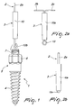
- the reference numeral 1 generally designates an intra-bone screw for extradental anchoring
- the reference numeral 2 designates a metallic wire designed to protrude from the oral mucosa
- the reference numeral 3 designates the respective mutual coupling means, particularly for orthodontic use according to the invention.
- the screw 1 comprises a threaded and frustum-shaped portion 4 designed to be screwed into the bone of the gum and a portion 5 that remains outside the bone and can have advantageously a portion 6 that is prism-shaped with a cross-section that is for example hexagonal and is surmounted by a tubular part 7 that has a reduced diameter: a hole 8 of the tubular part 7 is extended within the screw with a dead portion 9.
- the metallic wire 2 of the type used for orthodontic work can have different diameters and can be made of different materials: for example, the diameter of the wire can be comprised between 0.3 and 1.2 millimeters.
- the dead portion 9 of the screw 1 can have, for example, a diameter comprised between 0.9 and 1.2 millimeters.
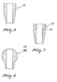
- the means 3 for coupling the wire 2 to the screw 1 are constituted by a conical pin 10, with an axial hole 11 whose outer surface 10a is frustum-shaped and converges toward the blocked end of the dead portion 9 of the screw 1 within which it is designed to be forced in order to anchor itself jointly, by way of its external taper, to the walls of the hole 8 of the screw 1.
- the axial hole 11 of the pin 10 must have such dimensions as to leave no less than one tenth of a millimeter of thickness at the tapered end of the pin 10.
- the end of the wire 2 has a larger tip that can be provided in various manners according to the requirements: the axial hole 11 can have a diameter that is substantially equal to the diameter of the wire 2, as shownn in Figure 5 , and in this case the larger tip is constituted by a head 12a of the wire 2.
- Figure 3 illustrates a pin 10 with an axial hole 11 whose diameter is slightly larger than twice the diameter of the wire 2: the end of the wire 2 is bent to provide a curl 12b whose outside dimensions are larger than the diameter of the axial hole 11 of the conical pin 10, in order to prevent axial extraction of the wire 2 from the pin 10 while allowing free rotation of the wire 2 about the axis of the screw 1.
- Figure 4 illustrates a pin 10 whose axial hole 11 has a diameter that is slightly larger than twice the diameter of the wire 2; the wire 2 is substantially bent in a U-shape, with two arms 2b, 2c mutually close and forming a loop 13 that protrudes from the converging end of the pin 10.
- the wire 2 can be made of elastic metallic alloy and if its elasticity is activated (especially for thinner wires), its free end or ends that protrude from the oral mucosa are each adapted to transmit a force that is parallel to the major axis of the screw 1 and has an intrusive or extrusive direction with respect to the gum, depending on the activation preloading to which it is subjected: in this case, the arms 2b, 2c of the wire 2 are bent substantially at 90° and are mutually opposite so as to arrange themselves substantially in mutual alignment.
- the operation of the intra-bone screw according to the invention is as follows.
- the length of the axially perforated conical pin 10 may be any and in particular may be short so as to enter only the end portion 9 of the hole 8 of the screw 1 or long in order to enter deeply, and the screw can be of the type in which the end of the head is provided or not with the tubular part 7 that has a reduced diameter.
- the wire 2 is arranged around the head of the conical pin 10 so that it is engaged stably within an outer perimetric groove 16 and can rotate freely thereon (the wire 2 is in fact coiled around the pin 10 at the groove 16).
- the pin 10 comprises a longitudinal notch 103 (in this case in an upper region) in order to allow easy elastic deformation thereof during insertion in the hole 8.
Landscapes
- Health & Medical Sciences (AREA)
- Oral & Maxillofacial Surgery (AREA)
- Dentistry (AREA)
- Epidemiology (AREA)
- Life Sciences & Earth Sciences (AREA)
- Animal Behavior & Ethology (AREA)
- General Health & Medical Sciences (AREA)
- Public Health (AREA)
- Veterinary Medicine (AREA)
- Dental Tools And Instruments Or Auxiliary Dental Instruments (AREA)
Claims (6)
- Système destiné en particulier à une utilisation orthodontique, comprenant une vis intra-osseuse (1) pour un ancrage extradentaire, des moyens (3) permettant le couplage à la vis intra-osseuse (1) d'un fil métallique (2) faisant saillie depuis la muqueuse buccale et le fil métallique (2), lesdits moyens (3) permettant le couplage du fil métallique (2) à la vis (1) étant adaptés à permettre la rotation libre mais pas le glissement axial du fil (2) relativement à la vis (1), afin d'empêcher la transmission à la vis (1) de couples qui risquent de gêner le processus de cicatrisation de la gencive en autorisant en même temps la transmission d'autres forces quels que soient l'orientation et le décalage axial de celles-ci, la tête de la vis (1) étant traversée axialement par un orifice borgne (8, 9) caractérisé en ce que ledit fil (2) comporte une partie montée de façon à pouvoir tourner librement dans l'orifice axial (11) d'une broche conique (10) adaptée à être forcée dans l'orifice (8, 9) de la vis (1), ledit fil (2) ayant un bout plus large (12a, 12b, 13) qui fait saillie depuis ledit orifice axial (11) de l'extrémité convergente de ladite broche (10), une partie du fil (2) faisant saillie depuis l'extrémité divergente de ladite broche (10) étant conçue de façon à faire partie d'un point d'ancrage ou de former le point d'ancrage d'éléments orthodontiques ou prothétiques.
- Système suivant la revendication 1, caractérisé en ce que le diamètre dudit fil (2) est essentiellement identique au diamètre de l'orifice (11) de la broche conique (10) et en ce que le bout plus large consiste en une sorte de tête (12a) prévue à l'extrémité du fil (2).
- Système suivant la revendication 1, caractérisé en ce que le diamètre dudit orifice axial (11) de la broche conique (10) est légèrement supérieur à deux fois le diamètre du fil (2) et en ce que l'extrémité du fil (2) est courbée de façon à former une boucle (12b) qui constitue ledit bout plus large.
- Système suivant la revendication 1, caractérisé en ce que le diamètre dudit orifice axial (11) de la broche conique (10) est légèrement supérieur à deux fois le diamètre du fil (2) et en ce que ledit fil (2) est essentiellement courbé en forme de U avec les branches mutuellement fermées (2b, 2c) formant une boucle (13) qui fait saillie de l'extrémité convergente de la broche (10).
- Système suivant une ou plusieurs des revendications précédentes, caractérisé en ce que ledit fil (2) est réalisé en un alliage métallique élastique et en ce que, lorsque son élasticité est activée, son extrémité libre (2a) ou ses extrémités (2b, 2c) peuvent transmettre des forces qui sont parallèles à l'axe principal de la vis (1) et qui présentent une orientation intrusive ou extrusive relativement à la gencive.
- Système suivant une ou plusieurs des revendications précédentes, caractérisé en ce que la partie de la broche (10) qui fait saillie depuis la vis (1) est sphéroidale (17) ou cylindrique (14) ou cylindrique (15) avec une rainure périmétrique extérieure (16).
Applications Claiming Priority (2)
| Application Number | Priority Date | Filing Date | Title |
|---|---|---|---|
| ITBO20080370 ITBO20080370A1 (it) | 2008-06-11 | 2008-06-11 | Vite intra-ossea per ancoraggio extra-dentale e filo metallico con mezzi di accoppiamento reciproco, particolarmente per uso ortodontico |
| PCT/EP2009/057170 WO2009150175A1 (fr) | 2008-06-11 | 2009-06-10 | Vis intra-osseuse pour ancrage extra-dentaire et fil métallique comportant des moyens de couplage réciproque, destinés en particulier à l’orthodontie |
Publications (2)
| Publication Number | Publication Date |
|---|---|
| EP2296576A1 EP2296576A1 (fr) | 2011-03-23 |
| EP2296576B1 true EP2296576B1 (fr) | 2013-03-13 |
Family
ID=40301559
Family Applications (1)
| Application Number | Title | Priority Date | Filing Date |
|---|---|---|---|
| EP09761738A Active EP2296576B1 (fr) | 2008-06-11 | 2009-06-10 | Vis intra-osseuse pour ancrage extra-dentaire et fil métallique comportant des moyens de couplage réciproque, destinés en particulier à l'orthodontie |
Country Status (3)
| Country | Link |
|---|---|
| EP (1) | EP2296576B1 (fr) |
| IT (1) | ITBO20080370A1 (fr) |
| WO (1) | WO2009150175A1 (fr) |
Families Citing this family (3)
| Publication number | Priority date | Publication date | Assignee | Title |
|---|---|---|---|---|
| US9060809B2 (en) | 2001-10-18 | 2015-06-23 | Orthoip, Llc | Lagwire system and method for the fixation of bone fractures |
| US8828067B2 (en) | 2001-10-18 | 2014-09-09 | Orthoip, Llc | Bone screw system and method |
| US20130012955A1 (en) * | 2010-03-17 | 2013-01-10 | Dean Lin | System and Method for Pedicle Screw Placement in Vertebral Alignment |
Family Cites Families (1)
| Publication number | Priority date | Publication date | Assignee | Title |
|---|---|---|---|---|
| ITPR20060040A1 (it) * | 2006-04-28 | 2007-10-29 | Antonio Costa | Dispositivo ortodontico a vite e filo e procedimento di assemblaggio del suddetto dispositivo ortodontico tramite un dispositivo ortodontico a filo ed un dispositivo ortodontico a vite. |
-
2008
- 2008-06-11 IT ITBO20080370 patent/ITBO20080370A1/it unknown
-
2009
- 2009-06-10 EP EP09761738A patent/EP2296576B1/fr active Active
- 2009-06-10 WO PCT/EP2009/057170 patent/WO2009150175A1/fr not_active Ceased
Also Published As
| Publication number | Publication date |
|---|---|
| ITBO20080370A1 (it) | 2009-12-12 |
| EP2296576A1 (fr) | 2011-03-23 |
| WO2009150175A1 (fr) | 2009-12-17 |
Similar Documents
| Publication | Publication Date | Title |
|---|---|---|
| JP5177698B2 (ja) | インプラントの挿入装置 | |
| US5620321A (en) | Orthodontic appliance | |
| JP4174070B2 (ja) | 骨接合固定要素 | |
| US6872209B2 (en) | Spinal implant connection assembly | |
| CN102665576B (zh) | 保护套筒保持设备 | |
| AU2016204646B2 (en) | Angle-variable bone screw fixation arrangement | |
| US20090042160A1 (en) | Orthodontic arch wire | |
| KR102730608B1 (ko) | 임플란트 시스템 | |
| US20130280670A1 (en) | Orthodontic Appliance and Method for Class II and Class III Malocclusion and Dental Asymmetric Correction | |
| WO2005065413A3 (fr) | Ensembles d'ancrage osseux et leurs procedes de fabrication | |
| EP3636188A2 (fr) | Tête de vis à serrage automatique | |
| US20120070797A1 (en) | Orthodontic Appliance and Method for Class II and Class III Malocclusion and Dental Asymmetric Correction | |
| KR102461049B1 (ko) | 치아 보철 시스템 | |
| CN109996513A (zh) | 螺旋件驱动器和用于外科应用的螺旋件 | |
| US20170296306A1 (en) | Orthodontic appliance and method for class ii and class iii malocclusion and dental asymmetric correction | |
| US6322357B1 (en) | Telescoping flexible bite jumping device | |
| EP2296576B1 (fr) | Vis intra-osseuse pour ancrage extra-dentaire et fil métallique comportant des moyens de couplage réciproque, destinés en particulier à l'orthodontie | |
| WO2007125561A1 (fr) | Vis intra-osseuse pour fixation exta-dentaire et fil avec organe de raccord mutuel, destinés en particulier à un usage orthondotique | |
| US20110053109A1 (en) | Orthodontic anchoring screw | |
| EP3206607B1 (fr) | Clou centro-medullaire | |
| CN106901848B (zh) | 一种支抗钉 | |
| WO2009125085A2 (fr) | Dispositif d'ancrage trans-cortical | |
| CN109394325B (zh) | 一种可调节髓内钉及医用植入固定系统 | |
| JP2019516453A (ja) | ハンドリングツール、歯科用セット及び歯科コンポーネントを組み立てるための方法 | |
| CN209847354U (zh) | 一种医用植入拉力螺钉、髓内钉及固定系统 |
Legal Events
| Date | Code | Title | Description |
|---|---|---|---|
| PUAI | Public reference made under article 153(3) epc to a published international application that has entered the european phase |
Free format text: ORIGINAL CODE: 0009012 |
|
| 17P | Request for examination filed |
Effective date: 20101216 |
|
| AK | Designated contracting states |
Kind code of ref document: A1 Designated state(s): AT BE BG CH CY CZ DE DK EE ES FI FR GB GR HR HU IE IS IT LI LT LU LV MC MK MT NL NO PL PT RO SE SI SK TR |
|
| AX | Request for extension of the european patent |
Extension state: AL BA RS |
|
| DAX | Request for extension of the european patent (deleted) | ||
| 17Q | First examination report despatched |
Effective date: 20120227 |
|
| GRAP | Despatch of communication of intention to grant a patent |
Free format text: ORIGINAL CODE: EPIDOSNIGR1 |
|
| GRAS | Grant fee paid |
Free format text: ORIGINAL CODE: EPIDOSNIGR3 |
|
| GRAA | (expected) grant |
Free format text: ORIGINAL CODE: 0009210 |
|
| AK | Designated contracting states |
Kind code of ref document: B1 Designated state(s): AT BE BG CH CY CZ DE DK EE ES FI FR GB GR HR HU IE IS IT LI LT LU LV MC MK MT NL NO PL PT RO SE SI SK TR |
|
| REG | Reference to a national code |
Ref country code: GB Ref legal event code: FG4D |
|
| REG | Reference to a national code |
Ref country code: CH Ref legal event code: EP Ref country code: AT Ref legal event code: REF Ref document number: 600326 Country of ref document: AT Kind code of ref document: T Effective date: 20130315 |
|
| REG | Reference to a national code |
Ref country code: IE Ref legal event code: FG4D |
|
| REG | Reference to a national code |
Ref country code: DE Ref legal event code: R096 Ref document number: 602009013937 Country of ref document: DE Effective date: 20130508 |
|
| PG25 | Lapsed in a contracting state [announced via postgrant information from national office to epo] |
Ref country code: LT Free format text: LAPSE BECAUSE OF FAILURE TO SUBMIT A TRANSLATION OF THE DESCRIPTION OR TO PAY THE FEE WITHIN THE PRESCRIBED TIME-LIMIT Effective date: 20130313 Ref country code: BG Free format text: LAPSE BECAUSE OF FAILURE TO SUBMIT A TRANSLATION OF THE DESCRIPTION OR TO PAY THE FEE WITHIN THE PRESCRIBED TIME-LIMIT Effective date: 20130613 Ref country code: ES Free format text: LAPSE BECAUSE OF FAILURE TO SUBMIT A TRANSLATION OF THE DESCRIPTION OR TO PAY THE FEE WITHIN THE PRESCRIBED TIME-LIMIT Effective date: 20130624 Ref country code: SE Free format text: LAPSE BECAUSE OF FAILURE TO SUBMIT A TRANSLATION OF THE DESCRIPTION OR TO PAY THE FEE WITHIN THE PRESCRIBED TIME-LIMIT Effective date: 20130313 Ref country code: NO Free format text: LAPSE BECAUSE OF FAILURE TO SUBMIT A TRANSLATION OF THE DESCRIPTION OR TO PAY THE FEE WITHIN THE PRESCRIBED TIME-LIMIT Effective date: 20130613 |
|
| REG | Reference to a national code |
Ref country code: AT Ref legal event code: MK05 Ref document number: 600326 Country of ref document: AT Kind code of ref document: T Effective date: 20130313 |
|
| REG | Reference to a national code |
Ref country code: NL Ref legal event code: VDEP Effective date: 20130313 |
|
| REG | Reference to a national code |
Ref country code: LT Ref legal event code: MG4D |
|
| PG25 | Lapsed in a contracting state [announced via postgrant information from national office to epo] |
Ref country code: FI Free format text: LAPSE BECAUSE OF FAILURE TO SUBMIT A TRANSLATION OF THE DESCRIPTION OR TO PAY THE FEE WITHIN THE PRESCRIBED TIME-LIMIT Effective date: 20130313 Ref country code: GR Free format text: LAPSE BECAUSE OF FAILURE TO SUBMIT A TRANSLATION OF THE DESCRIPTION OR TO PAY THE FEE WITHIN THE PRESCRIBED TIME-LIMIT Effective date: 20130614 Ref country code: LV Free format text: LAPSE BECAUSE OF FAILURE TO SUBMIT A TRANSLATION OF THE DESCRIPTION OR TO PAY THE FEE WITHIN THE PRESCRIBED TIME-LIMIT Effective date: 20130313 Ref country code: SI Free format text: LAPSE BECAUSE OF FAILURE TO SUBMIT A TRANSLATION OF THE DESCRIPTION OR TO PAY THE FEE WITHIN THE PRESCRIBED TIME-LIMIT Effective date: 20130313 |
|
| PG25 | Lapsed in a contracting state [announced via postgrant information from national office to epo] |
Ref country code: BE Free format text: LAPSE BECAUSE OF FAILURE TO SUBMIT A TRANSLATION OF THE DESCRIPTION OR TO PAY THE FEE WITHIN THE PRESCRIBED TIME-LIMIT Effective date: 20130313 Ref country code: HR Free format text: LAPSE BECAUSE OF FAILURE TO SUBMIT A TRANSLATION OF THE DESCRIPTION OR TO PAY THE FEE WITHIN THE PRESCRIBED TIME-LIMIT Effective date: 20130313 |
|
| PG25 | Lapsed in a contracting state [announced via postgrant information from national office to epo] |
Ref country code: NL Free format text: LAPSE BECAUSE OF FAILURE TO SUBMIT A TRANSLATION OF THE DESCRIPTION OR TO PAY THE FEE WITHIN THE PRESCRIBED TIME-LIMIT Effective date: 20130313 Ref country code: CZ Free format text: LAPSE BECAUSE OF FAILURE TO SUBMIT A TRANSLATION OF THE DESCRIPTION OR TO PAY THE FEE WITHIN THE PRESCRIBED TIME-LIMIT Effective date: 20130313 Ref country code: AT Free format text: LAPSE BECAUSE OF FAILURE TO SUBMIT A TRANSLATION OF THE DESCRIPTION OR TO PAY THE FEE WITHIN THE PRESCRIBED TIME-LIMIT Effective date: 20130313 Ref country code: RO Free format text: LAPSE BECAUSE OF FAILURE TO SUBMIT A TRANSLATION OF THE DESCRIPTION OR TO PAY THE FEE WITHIN THE PRESCRIBED TIME-LIMIT Effective date: 20130313 Ref country code: SK Free format text: LAPSE BECAUSE OF FAILURE TO SUBMIT A TRANSLATION OF THE DESCRIPTION OR TO PAY THE FEE WITHIN THE PRESCRIBED TIME-LIMIT Effective date: 20130313 Ref country code: IS Free format text: LAPSE BECAUSE OF FAILURE TO SUBMIT A TRANSLATION OF THE DESCRIPTION OR TO PAY THE FEE WITHIN THE PRESCRIBED TIME-LIMIT Effective date: 20130713 Ref country code: PT Free format text: LAPSE BECAUSE OF FAILURE TO SUBMIT A TRANSLATION OF THE DESCRIPTION OR TO PAY THE FEE WITHIN THE PRESCRIBED TIME-LIMIT Effective date: 20130715 Ref country code: EE Free format text: LAPSE BECAUSE OF FAILURE TO SUBMIT A TRANSLATION OF THE DESCRIPTION OR TO PAY THE FEE WITHIN THE PRESCRIBED TIME-LIMIT Effective date: 20130313 |
|
| PG25 | Lapsed in a contracting state [announced via postgrant information from national office to epo] |
Ref country code: PL Free format text: LAPSE BECAUSE OF FAILURE TO SUBMIT A TRANSLATION OF THE DESCRIPTION OR TO PAY THE FEE WITHIN THE PRESCRIBED TIME-LIMIT Effective date: 20130313 Ref country code: CY Free format text: LAPSE BECAUSE OF FAILURE TO SUBMIT A TRANSLATION OF THE DESCRIPTION OR TO PAY THE FEE WITHIN THE PRESCRIBED TIME-LIMIT Effective date: 20130313 |
|
| PLBE | No opposition filed within time limit |
Free format text: ORIGINAL CODE: 0009261 |
|
| STAA | Information on the status of an ep patent application or granted ep patent |
Free format text: STATUS: NO OPPOSITION FILED WITHIN TIME LIMIT |
|
| PG25 | Lapsed in a contracting state [announced via postgrant information from national office to epo] |
Ref country code: MC Free format text: LAPSE BECAUSE OF FAILURE TO SUBMIT A TRANSLATION OF THE DESCRIPTION OR TO PAY THE FEE WITHIN THE PRESCRIBED TIME-LIMIT Effective date: 20130313 Ref country code: DK Free format text: LAPSE BECAUSE OF FAILURE TO SUBMIT A TRANSLATION OF THE DESCRIPTION OR TO PAY THE FEE WITHIN THE PRESCRIBED TIME-LIMIT Effective date: 20130313 |
|
| REG | Reference to a national code |
Ref country code: CH Ref legal event code: PL |
|
| 26N | No opposition filed |
Effective date: 20131216 |
|
| GBPC | Gb: european patent ceased through non-payment of renewal fee |
Effective date: 20130613 |
|
| REG | Reference to a national code |
Ref country code: IE Ref legal event code: MM4A |
|
| REG | Reference to a national code |
Ref country code: DE Ref legal event code: R097 Ref document number: 602009013937 Country of ref document: DE Effective date: 20131216 |
|
| REG | Reference to a national code |
Ref country code: FR Ref legal event code: ST Effective date: 20140228 |
|
| PG25 | Lapsed in a contracting state [announced via postgrant information from national office to epo] |
Ref country code: CH Free format text: LAPSE BECAUSE OF NON-PAYMENT OF DUE FEES Effective date: 20130630 Ref country code: GB Free format text: LAPSE BECAUSE OF NON-PAYMENT OF DUE FEES Effective date: 20130613 Ref country code: IE Free format text: LAPSE BECAUSE OF NON-PAYMENT OF DUE FEES Effective date: 20130610 Ref country code: LI Free format text: LAPSE BECAUSE OF NON-PAYMENT OF DUE FEES Effective date: 20130630 |
|
| PG25 | Lapsed in a contracting state [announced via postgrant information from national office to epo] |
Ref country code: FR Free format text: LAPSE BECAUSE OF NON-PAYMENT OF DUE FEES Effective date: 20130701 |
|
| PG25 | Lapsed in a contracting state [announced via postgrant information from national office to epo] |
Ref country code: MT Free format text: LAPSE BECAUSE OF FAILURE TO SUBMIT A TRANSLATION OF THE DESCRIPTION OR TO PAY THE FEE WITHIN THE PRESCRIBED TIME-LIMIT Effective date: 20130313 |
|
| PG25 | Lapsed in a contracting state [announced via postgrant information from national office to epo] |
Ref country code: TR Free format text: LAPSE BECAUSE OF FAILURE TO SUBMIT A TRANSLATION OF THE DESCRIPTION OR TO PAY THE FEE WITHIN THE PRESCRIBED TIME-LIMIT Effective date: 20130313 |
|
| PG25 | Lapsed in a contracting state [announced via postgrant information from national office to epo] |
Ref country code: LU Free format text: LAPSE BECAUSE OF NON-PAYMENT OF DUE FEES Effective date: 20130610 Ref country code: HU Free format text: LAPSE BECAUSE OF FAILURE TO SUBMIT A TRANSLATION OF THE DESCRIPTION OR TO PAY THE FEE WITHIN THE PRESCRIBED TIME-LIMIT; INVALID AB INITIO Effective date: 20090610 Ref country code: MK Free format text: LAPSE BECAUSE OF FAILURE TO SUBMIT A TRANSLATION OF THE DESCRIPTION OR TO PAY THE FEE WITHIN THE PRESCRIBED TIME-LIMIT Effective date: 20130313 |
|
| PGFP | Annual fee paid to national office [announced via postgrant information from national office to epo] |
Ref country code: DE Payment date: 20210628 Year of fee payment: 13 |
|
| REG | Reference to a national code |
Ref country code: DE Ref legal event code: R082 Ref document number: 602009013937 Country of ref document: DE Representative=s name: SCHIEBER - FARAGO PATENTANWAELTE, DE Ref country code: DE Ref legal event code: R082 Ref document number: 602009013937 Country of ref document: DE Representative=s name: FARAGO PATENTANWALTSGESELLSCHAFT MBH, DE |
|
| REG | Reference to a national code |
Ref country code: DE Ref legal event code: R082 Ref document number: 602009013937 Country of ref document: DE Representative=s name: SCHIEBER - FARAGO PATENTANWAELTE, DE |
|
| REG | Reference to a national code |
Ref country code: DE Ref legal event code: R119 Ref document number: 602009013937 Country of ref document: DE |
|
| PG25 | Lapsed in a contracting state [announced via postgrant information from national office to epo] |
Ref country code: DE Free format text: LAPSE BECAUSE OF NON-PAYMENT OF DUE FEES Effective date: 20230103 |
|
| PGFP | Annual fee paid to national office [announced via postgrant information from national office to epo] |
Ref country code: IT Payment date: 20250520 Year of fee payment: 17 |