EP2296860B1 - Moule pour pneu ayant un système d'ouverture de moule efficace - Google Patents
Moule pour pneu ayant un système d'ouverture de moule efficace Download PDFInfo
- Publication number
- EP2296860B1 EP2296860B1 EP08781207.9A EP08781207A EP2296860B1 EP 2296860 B1 EP2296860 B1 EP 2296860B1 EP 08781207 A EP08781207 A EP 08781207A EP 2296860 B1 EP2296860 B1 EP 2296860B1
- Authority
- EP
- European Patent Office
- Prior art keywords
- mold
- pin
- aperture
- sections
- section
- Prior art date
- Legal status (The legal status is an assumption and is not a legal conclusion. Google has not performed a legal analysis and makes no representation as to the accuracy of the status listed.)
- Active
Links
Images


Classifications
-
- B—PERFORMING OPERATIONS; TRANSPORTING
- B29—WORKING OF PLASTICS; WORKING OF SUBSTANCES IN A PLASTIC STATE IN GENERAL
- B29D—PRODUCING PARTICULAR ARTICLES FROM PLASTICS OR FROM SUBSTANCES IN A PLASTIC STATE
- B29D30/00—Producing pneumatic or solid tyres or parts thereof
- B29D30/06—Pneumatic tyres or parts thereof (e.g. produced by casting, moulding, compression moulding, injection moulding, centrifugal casting)
- B29D30/0601—Vulcanising tyres; Vulcanising presses for tyres
- B29D30/0606—Vulcanising moulds not integral with vulcanising presses
- B29D30/0629—Vulcanising moulds not integral with vulcanising presses with radially movable sectors
- B29D2030/063—Vulcanising moulds not integral with vulcanising presses with radially movable sectors the moulds being split in upper and lower halves
Definitions
- This invention relates generally to curing molds, and, more specifically, to apparatus for controlling the opening and/or closing of curing molds that may be segmented and/or split-type.
- Molds for curing objects may comprise a split mold.
- a split mold generally includes an upper mold portion and a lower mold portion, each of which translate vertically between open and closed positions.
- Each of the upper and lower portions of the mold may generally be segmented into a plurality of arcuate sections. During or subsequent vertical translation, the sections of the upper and lower portions translate outwardly in a radial direction. The radial translation of the sections facilitates the demolding of the cured object.
- An example for an split mold for tires is disclosed in GB 1 248 891 A .
- a tire having a complex tread design may be difficult to demold without the radial portion of the mold translating outwardly, as portions of the mold sections would remain within the molded tread to resist any force attempting to lift the tire vertically from the mold.
- a split-type and/or segmented mold generally includes a plurality of interoperable mold portions, it is important that the portions collapse inwardly to properly engage adjacent portions of the mold in a closed mold position, to eliminate the formation of any gaps there between. For example, when one or more sections collapse inwardly in a misaligned manner, adjacent portions will not engage properly. This may cause the sections to bind, and edges along the sections to wear or become damaged. The same can occur when the upper and lower mold portions become misaligned. Misaligned or worn edges generally form gaps in the closed mold and reduce the life of the damaged components. Worn edges and gaps results in the formation of flash along associated portions of the cured tire. Flash is rubber that is forced between adjacent plates and segments by pressurization encountered during tire curing processes.
- the present invention relates to a tire curing mold according to claim 1.
- the tire mold also includes a pin extending from a first section of each pair of upper and lower sections, and an aperture extending within a second section of each pair of upper and lower sections, the aperture including an opening and positioned for receiving a portion of the pin extending from the corresponding first section when the mold is in a substantially closed position.
- Particular embodiments of the present invention include a tire curing mold having a first plurality of sections arranged to form an expandable ring. A portion of the first plurality of sections forms a portion of a tire molding cavity. The sections of the first plurality are radially translatable between open and closed positions and form one or more first pairs of adjacent first sections.
- the tire mold further includes one or more first synchronization members extending between adjacent sections of each first pair, wherein each first synchronization member extends from one section to slidably engage the other section for each first pair of sections when the first plurality of sections are translating between the open and close positions.
- Particular embodiments of the present invention provide apparatus for controlling the opening and closing of a curing mold, and more specifically, a segmented and/or split-type curing mold.
- a split-type tire curing mold 10 comprises an upper mold portion 20 and a lower mold portion 30.
- Each mold portion 20, 30 is generally segmented into a plurality of sections 24, 34 respectively.
- One or more side plates 22, 32 each form a ring and engage the plurality of sections 24, 34, respectively, to form a tire molding cavity 18, where the side plates 22, 32 are generally associated with a sidewall of the cured tire, and sections 24, 34 are generally associated with the tread area of the cured tire.
- upper mold back 21 and upper side plates 22 are connected to an upper base plate 26, while lower mold back 31 and lower side plates 32 are connected to a lower base plate 36.
- Upper and lower sections 24, 34 are slidably engaged with each corresponding (adjacent) mold back 21, 31, and are forced upwardly and outwardly toward a mold open position, such as, for example, by a spring. Mold backs 21, 31 retain the plurality of sections 24, 34 in expandable ring-like arrangements, whereby sections 24, 34 slide between open and closed positions along the inclined conical surfaces 21a, 31a of each mold back 21, 31.
- a mold opening process is initiated by first vertically raising upper base plate 26, which includes raising upper side plates 22 and mold back 21 .
- upper mold back 21 As the upper mold back 21 is raised, the surface 27 of upper section 24 translates upwardly (vertically) and outwardly in a radial direction along conical surface 21a of upper mold back 21.
- surface 37 of lower section 34 translates along conical surface 31a of lower mold back 31. This allows upper and lower sections to generally remain in contact between surfaces 29, 39, or along parting line (or plane) 12, while the tire is being demolded from mold 10.
- This translation continues until sections 24, 34 reach a translational limit, after which the upper mold portion 20 is lifted vertically from lower mold portion 30 to provide access for tire removal. Demolding of the tire can become difficult, such as when any of the mold components become misaligned or tilted relative to other components, and/or when more complex and/or intricate tread designs resist demolding (i.e., resist separation from a section 24, 34).
- upper base plate 26 forces upper sections 24 into contact with lower sections 34 along surfaces 29, 39, and upper mold back 21 vertically downward, thereby directing sections 24 radially inward and downward, while also directing sections 34 downward and inward along bold back 31.
- the radial translation causes upper sections 24 to engage corresponding side plates 22 along surfaces 23, 25, and lower sections 34 to engage corresponding side plates 32 along surfaces 33, 35.
- sections 24, 34 engage the side surfaces of adjacent sections 24, 34 to form an upper and lower annulus of upper sections 24 and lower sections 34, respectively (shown in generally in FIG. 2 ).
- each pin-aperture combination 40 operates between adjacent pairs of sections 24, 34, whereby a pin 42 extends from a cavity 28, located within one of the upper and lower sections 24, 34, to engage an aperture 50 located within the other of the sections 24, 34.
- the pin-aperture combination 40 facilitates proper mold opening by generally maintaining radial alignment between adjacent sections 24, 34. More specifically, pin-aperture combination 40 maintains synchronized translation between upper and lower sections 24, 34 to reduce damage to the tire that may result from shearing and other forces generated during asynchronous translation of sections 24, 34.
- Pin-aperture combination 40 also transfers opening forces ( F V and F R ) to lower section 34 to assist in the demolding of lower section 34 from any resistive tire tread.
- Pin-aperture combination 40 also facilitates proper alignment between upper and lower mold portions 20, 30 during mold closure, thereby preventing/reducing damage to any mold components thereof that may arise due to misaligned engagement of such components. This also ensures that the same components properly seal tire cavity 18 to prevent/reduce the occurrence of flash along the tire (i.e., rubber expelled from the tire cavity, which results in waste and may affect tire integrity), and that the components are properly arranged to correctly form any desired features along the tire tread area and any other portion of the tire.
- At least one pin-aperture combination 40 is provided for each pair of sections 24, 34.
- an aperture 50 is formed in each surface 39 for use with pins 42 (positioned in adjacent upper sections 24) to form corresponding pin-aperture combinations 40.
- each pin-aperture combination 40 includes a pin 42 and an aperture 50, each extending from one of the parting line surfaces 29, 39 of upper and lower section 24, 34, respectively.
- pin 42 closely fits within aperture 50 to properly maintain upper and lower sections 24, 34 in alignment during mold opening by transferring opening forces (F V and F R ) to bottom section 34 to assist in tire demolding, and radially synchronizing the translation of upper and lower sections 24, 34 during opening and closing operations.
- pin 42 extends from surface 29 of upper section 24 into aperture 50, which extends within lower section 34. Still, it is contemplated that pin 42 may extend from lower section 34, and aperture 50 from upper section 24.
- pin 42 may include any shaped cross-section, such as, for example, a circular or square cross-section. Further, over the length of pin 42, the cross-section may be substantially constant, to provide a generally straight pin, which may form, for example, a cylinder or the like. In other embodiments, such as those shown in the FIGURES, the cross-section may vary as desired to provide a contoured pin 42, which may include, for example, tapers, recesses, ridges, or cavities positioned along the exterior surface of pin 42. It is also contemplated that pin 42 may be formed of any known material, such as, for example, steel, aluminum, or any alloy thereof.
- pin 42 may generally include an alignment portion 46 that closely fits within an opening 53 of aperture 50.
- Alignment portion 46 comprises one or more exterior surfaces of pin 42 for interacting with opening 53.
- alignment portion 46 is sized to closely approximate the size of (i.e., the innermost extent of) opening 53, which may include a small gap existing between the pin 42 and opening 53. The small gap may account for any manufacturing imperfections or differences in expansion between the components, and/or may provide additional space for easier alignment and insertion of pin 42 into opening 53.
- Alignment portion 46 may transfer radial opening and closing forces (F R ) from the upper mold section 24 to the lower mold section 34, and may align the upper and lower sections 24, 34 when alignment portion 46 is positioned within opening 53 when mold 10 is in a closed position, which is shown in FIGS. 1 and 3 in a particular embodiment.
- Alignment of upper and lower sections 24, 34 facilitates proper alignment and engagement of sections 24, 34 with adjacent sections 24, 34, which also facilitates proper engagement with adjacent side plates 22, 32 for the purpose of reducing/eliminating damage to the edges of sections 24, 34 and side plates 22, 32.
- Alignment of sections 24, 34 also reduces/eliminates the formation of flash that may arise from misalignment and wear, and facilitates proper formation of tread elements and other tire surface features.
- Pin 42 may also include an attachment portion 44 for securing pin 42 to a corresponding section 24, 34.
- Pin attachment portion 44 generally facilitates securement of pin 42 within a corresponding mold section 24, 34.
- pin 42 may be secured to a corresponding mold section 24, 34 by any known method, which includes welding or use of any known fastener, such as a bolt, adhesive, or interference fit.
- a fastener may extend axially through at least a portion of pin 42, or may extend through one or more flanges extending from a side of pin 42, in similar fashion to the bolts and flanges shown in FIG. 6 in association with an alternative embodiment of aperture 50.
- attachment portion 44 may comprise a surface of pin 42, such as for welding or threaded attachment.
- pin 42 includes an attachment portion 44 that extends into mold section 24, the attachment portion having threaded sides 44a for securing attachment portion 44 within a cavity, such as a corresponding sub-cavity 28a, which is located within corresponding mold section 24. Accordingly, one or more surfaces 45 may be provided for applying torque or other forces for securing attachment portion 44 within sub-cavity 28a .
- portion 44 comprises a hexagonal cross-section having a plurality of exterior surfaces for engaging a tool or other device to rotatably secure attachment portion 44 within section mold 24. Securement surfaces 45 may be contained within cavity 28, and more specifically, within sub-cavity 28b .
- the pin 42 includes a ridge 49 for engaging a ledge 54, which may or may not be formed in association with opening 53.
- ledge 54 is formed in association with inwardly extending opening 53.
- radial opening forces F R may be transferred from alignment portion 46 to opening 53, as generally shown in FIG. 3 .
- alignment portion 46 may become disengaged from opening 53.
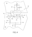
- ridge 49 is provided to regain pin engagement with opening 53, as generally shown in FIG. 4 . Disengagement may result, for example, when lower mold section 34 will not release (i.e., demold) from the tire.
- ridge 49 may transmit vertical F V as well as radial opening forces F R to lower mold section 34 by way of ledge 54, as shown in FIG. 4 in a particular embodiment.
- Ridge 49 may include a surface 49a for engaging ledge 54.
- ridge surface 49a and ledge 54 may form similarly-contoured and similarly arranged interoperable surfaces to maximize contact during engagement. It is contemplated that either ridge 49 or ledge 54 may instead form a recess, wherein the other of the ridge 49 or ledge 54 may extend during engagement.
- pin 42 is recentered within aperture 50, during which ridge 49 and ledge 54 disengage, before pin 42 is lifted vertically from aperture 50.
- ridge 49 may be located at an end of pin 42, as shown in the FIGURES, or at any other location along the length of pin 42.
- an extension 48 may extend between ridge 49 and alignment portion 46, which may be used to engage opening 53 when ridge 49 is engaged with ledge 54.
- pin 42 includes a tapered bottom surface 49b, which is located at the distal end of pin 42 for the purpose of assisting with the repositioning of pin 42 within aperture 50 during mold closure operations.
- tapered bottom surface 49b is located in association with ridge 49, as shown in the FIGURES, although this association may not exist in other embodiments.
- aperture 50 generally extends within a mold section 24, 34.
- aperture 50 forms an aperture cavity 51 extending within any such section 24, 34.
- aperture 50 forms an insert 52 that is placed within aperture cavity 51.
- any feature discussed in association with aperture 50 may be formed in association with aperture cavity 51 or with insert 52. Therefore, in the discussions herein, when referencing aperture 50, cavity 51 and insert 52 are also referenced and contemplated.
- aperture forms an insert 52 placed and secured within aperture cavity 51.
- An insert 52 may be placed within cavity 51 and used to interact with pin 42, such as when it is desired that a material other than the corresponding section 24, 34 material be used to interact with pin 42.
- section 24, 34 is made of aluminum, it may be desired to use an insert 52 formed of steel. It may also be desirous to utilize an insert 52, which may be easier to manufacture in lieu of forming cavity 51 to achieve the desired features of aperture 50.
- Cavity 51 and insert 52, and any features thereof, may be formed by any known method, such as by machining, molding, or casting. Insert 52 may be secured within aperture cavity 51 by any known means, such as, for example, by a threaded portion, fasteners, adhesive, or welding.
- an insert 52 may form a sleeve-like structure, having an opening 53 extending from downwardly extending sidewalls 56.
- insert 52 may form a ring-like structure, which generally does not include sidewalls 56 extending downwardly from opening 53.
- the ring-like insert 52 may be secured within aperture cavity 51 by any means discussed above in general association with insert 52, such as by threading (as shown with regard to other embodiments of insert 52 in FIGS. 1-5 ) or fasteners, as shown in FIG. 6 .
- FIG. 1-5 threading (as shown with regard to other embodiments of insert 52 in FIGS. 1-5 ) or fasteners, as shown in FIG. 6 .
- insert 52 is extended to form a tab 59, through which fasteners 59a are able to extend to secure insert 52 into section 34.
- any insert 52 may be formed from one or more interoperable components.
- aperture 50 generally includes an opening 53.
- opening 53 forms a portion of insert 52, which is positioned within aperture 50 for receiving pin 42.
- Opening 53 may extend inwardly from a side of aperture 50 at any location along the length of aperture 50 (i.e., cavity 51 or insert 52), as shown in the FIGURES in particular embodiments, or it may simply comprise a top surface of the aperture.
- Aperture 50 may also include an inwardly tapered surface 55 to assist in positioning pin 42 within opening 53 during mold closing operations. Tapered surface 55 may be located along a top surface of aperture 50, or may be located along a top surface of opening 53, as shown in the FIGURES in particular embodiments.
- aperture 50 also includes a ledge 54.
- Ledge 54 provides a surface that interoperates with ridge 49 formed along pin 42.
- Ledge 54 may be formed along any portion of aperture 50, such as, for example, as part of opening 53, which is shown in the FIGURES in particular embodiments, where a ledge is provided in association with an inwardly extending opening 53. It is contemplated it may be positioned in any other desirable location along the length of aperture 50.
- Ledge 54 generally extends inwardly into aperture 50. In the embodiments shown in the FIGURES, ledge 54 extends inwardly from a sidewall 56 of aperture 50, and more specifically, insert 52. However, it is contemplated that ledge 54 may reside within a recess positioned outwardly of sidewall 56 and extend inwardly toward sidewall 56 of aperture 50.
- mold 10 may include a compressible member 58 that is capable of controlling the collapse of a penetrating pin 42.
- Compressible member 58 controls the relative translation between upper and lower sections 24, 34 as each approaches engagement along parting line 12.
- aperture 50 includes a compressible member 58 that extends a height between aperture opening 53 and a bottom 57 of aperture 50.
- a plate 58a may extend along a top portion of compressible member 58 to provide a more uniform engagement between pin 42 and compressible member 58.
- Compressible member 58 may comprise any spring, which includes a coil spring, leaf spring, or rubber disk, or any other component capable of controlling the downward translation of pin 42, such as, for example, a piston or cylinder.
- each pin 42 is inserted into a corresponding aperture 50, and initially engages corresponding compressible members 58 in an extended orientation.
- One purpose of placing compressible members 58 within the plurality of apertures 50 is to synchronize the closing of sections 24, 34 upon each other as each approaches parting line 12. This promotes proper alignment of sections 24, 34 and a more uniform abutment of sections 24, 34 along parting line 12. Therefore, if one or more sections 24, 34 prematurely contact a compressible member 58 prior to other sections 24, 34, the compressible member 58 resists further substantial compression until a substantial quantity of pins 42 contact corresponding compressible members around mold 10. Once a substantial quantity of pins 42 are engaged, the corresponding sections 24, 34 uniformly translate toward the other section 24, 34 while compressing the compressible member 58 toward a mold closed position. Accordingly, compressible member 58 is compressed when the mold is in a closed position. During mold opening operations, compressible members 58 may assist in separating sections 24, 34 toward an open position.
- each combination 60 includes a synchronization member 62 that extends from a first side surface 72 of a section 24, 34 and into a synchronization member-receiving cavity 64 located in a second side surface 73 of an adjacent section 24, 34.
- members 62 may slide along an upper surface 66 of a corresponding cavity 64 during mold opening and closing operations to prevent adjacent sections from becoming misaligned.
- This engagement between member 62 and cavity 64 resists any vertical misalignment that may result due to gravity or other misalignments or wear within mold 10 that would cause one of the laterally adjacent sections 24, 34 to seek a lower vertical position relative to the other section 24, 34.
- the combination 60 of member 62 and cavity 64 maintains laterally adjacent sections 24, 34 within 1-2 millimeters (mm) of vertical misalignment. It is contemplated that member-receiving cavity 64 may not exist, and instead synchronization members 62 may engage other surfaces, such as an end surface 76 or a parting line surface 78.
- synchronization members 62 extend substantially parallel to the mold centerline CL (which is parallel to mold parting line 12 in the FIGURES); however, member 62 may extend in any other direction as desired.
- Cavity 64 may also extend radially outward from an interior surface, which may be substantially parallel to the mold centerline or at any desirous angle relative to the mold centerline CL (as shown exemplarily in the FIGURES). The angled extension of cavity 64 may be desired to account for a multi-directional translation of sections 24, 34 during opening and closing operations.
- Synchronization member 62 is generally defined by length L M , and extends into cavity 64 by a length L M,E when in a closed position.
- member 62 is 10 mm in diameter, and has a length L M of at least approximately 2.5 to 4 inches (63.5 to 102 mm).
- Other lengths L M may be used, whether larger or smaller, which may depend on the material used.
- the material is formed of steel, although other materials, such as aluminum, may be used.
- Member-receiving cavity 64 extends a length L C , which is sized to accommodate the extension length L M,E of member 62 when corresponding sections 24, 34 are in the closed (engaged) position.
- Member 62 may be arranged to extend within cavity 64 at any radial depth D C of cavity 64. Accordingly, offsets ⁇ may exist between synchronization member 62 and the inward and/or outward radial extents of cavity 64, when corresponding sections 24, 34 are in a closed position.
- an offset ⁇ is provided along an outer extent of member 62, between the outer extent of member 62 and the outer radial extent of cavity 64 along depth D C .
- a second offset ⁇ could be included along an inner side of member 62, between the inner extent of member 62 and the inner radial extent of cavity 64 along depth D C .
- Offsets ⁇ provide a buffer if the corresponding sections 24, 34 become radially misaligned. If offsets ⁇ were not present, member 62 may extend beyond section outer surface 74, which could interfere with other mold components, such as mold backs 21, 31. Member 62 may also be offset from the radial inner extent of cavity 64, to account for any manufacturing inaccuracies.
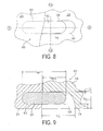
- FIGS. 11 and 12 generally show a pair of sections 24 radially translating during a mold opening operation by operation of radial forces F R .
- sections 24 are radially translating in a synchronized manner, where the offset ⁇ shown in FIG. 9 is not generally consumed by member 62.
- synchronization members 62 may comprise any structural member, such as a bar, pin, or tube, that extends from side 61 of a section 24, 34, into which member 62 is secured.
- Members 62 may be formed of any desired material, such as aluminum or steel, which may or may not be the same material used to form corresponding sections 24, 34.
- Member 62 may be placed and/or secured into each section 24, 34 by any known means, such as by way of a threaded portion (as shown in the FIGURES), interference fit, a fastener, an adhesive, or welding.
- the pin placed into a member-mounting cavity 63 without securement thereto.
- the corresponding member-receiving cavity 64 is located adjacent member 62, and may be positioned along any portion of second side surface 73. In particular embodiments, as shown in the FIGURES, member-receiving cavity 64 is located along an outer end surface 74 of the associated section 24, 34. It is contemplated that synchronization members 62 may or may not be used in cooperation with pin-aperture combinations 40, discussed above. It is also contemplated that synchronization members 62, of any embodiment discussed or contemplated, may not be limited for use in split-type molds, as non-split molds may equally benefit from the use of synchronization members 62 and member-receiving cavities 64.
- synchronization members 62 may extend from any surface of any section 24, 34. Accordingly, for example, the embodiment shown in FIGS. 13-14 provides one or more members 62 extending from an end surface 76 and/or a parting line surface 78 of any upper and/or lower section 24, 34. Parting line surface 78 generally represents surface 29 of upper section 24 and surface 39 of lower section 34.
- multiple synchronization members 62 shown as 62a, 62b extend from each section 24, 34, and across segment line (or plane) 70, which generally extends between adjacent sections 24 and adjacent sections 34. It is contemplated that in any embodiment, including those discussed in association with FIGS. 7-12 , multiple synchronization members 62 may extend from each section 24, 34 as desired, such as, for example, to provide additional strength or rigidity while maintaining sections 24, 34 in vertical alignment during opening and closing operations. In the embodiment shown in FIGS.
- a synchronization member 62 extends from each opposing section 24, 34 along segment line 70, wherein the synchronization members 62 are in close relation or substantially adjacent to each other to form a pair of synchronization members 62a, 62b that operate cooperatively to locally maintain a vertical alignment of the associated sections 24, 34. It is also contemplated that synchronization members 62 may extend from a plurality of locations without close association with other synchronization members 62, which is generally represented in one embodiment by FIGS. 7-12 . In other embodiments, such as the embodiments shown in FIGS.
- a cooperative pair of synchronization members 62a, 62b may not exist, and instead an independent member 62 may act along an end surface 76 or parting line surface 78 (i.e., only one of the pair may exist).
- synchronization members 62 whether provided as cooperative pairs of members 62a, 62b or as independent members 62, may exist along any surface of each section 24, 34, which includes surfaces 72, 73, 74, 76, and 78.
- the pair of cooperative members 62a, 62b shown in FIGS. 13-14 along end surface 76 and parting line surface 78 may exist along only one of the end surface 76 and parting line surface 78 (i.e., only one pair may extend between adjacent sections 24 or adjacent sections 34).
- a member-receiving cavity 64 may extend along end surface 76 and parting line surface 78 of each associated section 24, 34.
- a pair of cooperating synchronization members 62a, 62b may extend along any portion of segment line 70. Accordingly, the pair of members 62a, 62b may from a surface associated with a section 24, 34, and extend to engage a surface of the adjacent section 24, 34.
- Such surfaces include surfaces 72, 73, 74, 76, and 78. In other embodiments, including that shown in FIGS.
- At least one member of the pair of members 62a, 62b may extend to and/or from a member-receiving cavity 64, which comprises 64a and 64b. This may be desired to provide clearance between any member 62, including members 62a, 62b and other surrounding mold or press components.
- member 62a extends from cavity 64a and into cavity 64b
- corresponding member 62b extends from cavity 64b and into cavity 64a.
- Members 62a, 62b may be secured into corresponding sections 24, 34 by fasteners 65, or any other means of attachment or constraint, which includes welding, mechanical or frictional fit, or any other known method. Because the pair of members 62a, 62b may be located along surfaces 74 in similar fashion to the embodiments shown in FIGS. 7-12 , members 62a, 62b may simply be placed into an aperture along a corresponding surface 72,73.
Landscapes
- Engineering & Computer Science (AREA)
- Mechanical Engineering (AREA)
- Moulds For Moulding Plastics Or The Like (AREA)
- Heating, Cooling, Or Curing Plastics Or The Like In General (AREA)
Claims (9)
- Moule de cuisson de pneu (10) ayant une cavité de moulage de pneu (18), le moule (10) comprenant :une partie de moule supérieure (20) comportant une pluralité de sections supérieures (24) disposées de façon annulaire autour du moule (10) pour former une première partie (44) de la cavité de pneu (28) et pouvant translater radialement entre une position ouverte du moule et une position fermée du moule ;une partie de moule inférieure (30) comprenant une pluralité de sections inférieures (34) disposées de façon annulaire autour du moule (10) pour former une deuxième partie (44) de la cavité de pneu (28) et pouvant translater radialement entre les positions ouverte et fermée du moule, dans lequel chacune des sections inférieures (34) est positionnée de façon adjacente à l'une des sections supérieures (24) pour former une pluralité de paires de sections supérieure et inférieure (24, 34) ;une broche (42) s'étendant depuis une première section (24) de chaque paire de sections supérieure et inférieure (24, 34) ; etun trou (50) s'étendant dans une deuxième section (24) de chaque paire de sections supérieure et inférieure (24, 34), le trou (50) comportant une ouverture (53) positionnée pour recevoir une partie (44) de la broche (42) qui s'étend depuis la première section (24) correspondante quand le moule (10) est dans une position fermée, la broche (42) étant positionnée dans le trou (50) quand le moule (10) est dans la position fermée du moule, et retirée du trou (50) quand le moule (10) est dans la position ouverte du moule, caractérisé en ce quele trou (50) comprend un rebord (54) destiné à se mettre en prise avec une saillie (49) positionnée sur une longueur de la broche (42), le rebord (54) s'étendant en direction de l'intérieur du trou (50) et la saillie (49) s'étendant vers l'extérieur depuis un côté de la broche (42), la saillie de broche (49) ayant une première surface située du côté inférieur de la saillie (49) pour se mettre en prise avec le rebord (54) quand la broche (42) entre dans le trou (50) pendant les opérations de fermeture du moule (10), et la saillie de broche (49) ayant une deuxième surface (49a) située sur un côté supérieur de la saillie (49) pour se mettre en prise avec le rebord (54) quand la broche (42) est levée pendant les opérations d'ouverture (53) du moule.
- Moule (10) selon la revendication 1, dans lequel le trou (50) comprend en outre une surface rétrécie vers l'intérieur (55) pour diriger la broche (42) dans l'ouverture (53) du trou (50), et dans lequel la première surface de la saillie (49) est conique.
- Moule (10) selon la revendication 1, dans lequel la broche (42) comprend une partie d'alignement (46), la partie d'alignement (46) étant dimensionnée à la taille de l'ouverture du trou (53), la partie d'alignement (46) étant placée sur la longueur de la broche (42) entre la saillie (49) et la première section (24).
- Moule (10) selon la revendication 1, dans lequel le trou (50) comprend un élément compressible (58) positionné pour être mis en prise avec la broche (42) quand le trou (50) reçoit la broche (42) pendant les opérations de fermeture du moule (10).
- Moule (10) selon la revendication 4, dans lequel le trou (50) comprend en outre une plaque (58a) agissant le long d'une extrémité de l'élément compressible (58) pour se mettre en prise avec la broche (42).
- Moule (10) selon la revendication 4, dans lequel l'élément compressible (58) est un ressort.
- Moule (10) selon la revendication 1, comprenant en outre :une pluralité d'éléments de synchronisation verticale supérieurs (62), dans lequel chaque élément de synchronisation verticale supérieur (62) s'étend entre une paire d'une pluralité de paires adjacentes des sections supérieures (24), et depuis une première section (24) de chaque paire de sections supérieures (24) pour se mettre en prise de façon glissante avec une deuxième section (24) de chaque paire de sections supérieures (24) entre des positions de moule (10) ouvert et de moule fermé ; etune pluralité d'éléments de synchronisation verticale inférieurs (62), dans lequel chaque élément de synchronisation verticale inférieur (62) s'étend entre une paire d'une pluralité de paires adjacentes des sections inférieures (34), et depuis une première section (24) de chaque paire de sections inférieures (34) pour se mettre en prise de façon glissante avec une deuxième section (24) de chaque paire de sections supérieures (24) pendant que le moule (10) fonctionne entre des positions de moule ouvert et de moule fermé.
- Moule (10) selon la revendication 1, dans lequel la deuxième surface (49a) de la saillie (49) et le rebord (54) présentent un profil similaire.
- Moule (10) selon la revendication 4, dans lequel la broche (42) comprend une partie d'alignement (46), la partie d'alignement (46) étant dimensionnée à la taille de l'ouverture du trou (53), la partie d'alignement (46) étant placée sur la longueur de la broche (42) entre la saillie (49) positionnée sur une longueur de la broche (42) et la première section (24) depuis laquelle s'étend la broche (42).
Applications Claiming Priority (1)
| Application Number | Priority Date | Filing Date | Title |
|---|---|---|---|
| PCT/US2008/068847 WO2010002392A1 (fr) | 2008-06-30 | 2008-06-30 | Moule pour pneu ayant un système d'ouverture de moule efficace |
Publications (3)
| Publication Number | Publication Date |
|---|---|
| EP2296860A1 EP2296860A1 (fr) | 2011-03-23 |
| EP2296860A4 EP2296860A4 (fr) | 2012-12-12 |
| EP2296860B1 true EP2296860B1 (fr) | 2015-01-28 |
Family
ID=41466248
Family Applications (1)
| Application Number | Title | Priority Date | Filing Date |
|---|---|---|---|
| EP08781207.9A Active EP2296860B1 (fr) | 2008-06-30 | 2008-06-30 | Moule pour pneu ayant un système d'ouverture de moule efficace |
Country Status (5)
| Country | Link |
|---|---|
| US (1) | US8366427B2 (fr) |
| EP (1) | EP2296860B1 (fr) |
| CN (1) | CN102076472B (fr) |
| BR (1) | BRPI0822857B1 (fr) |
| WO (1) | WO2010002392A1 (fr) |
Families Citing this family (4)
| Publication number | Priority date | Publication date | Assignee | Title |
|---|---|---|---|---|
| FR2998829B1 (fr) * | 2012-12-04 | 2015-05-15 | Michelin & Cie | Moule de vulcanisation pour pneumatique |
| US9604423B2 (en) * | 2013-06-28 | 2017-03-28 | Compagnie Generale Des Etablissements Michelin | Tire mold with improved durability |
| CN110481073B (zh) * | 2019-08-21 | 2024-12-20 | 青岛森麒麟轮胎股份有限公司 | 防溢胶装置 |
| CN113246516B (zh) * | 2021-07-14 | 2021-10-08 | 山东豪迈机械科技股份有限公司 | 具有同步结构的轮胎两半活络模具 |
Family Cites Families (43)
| Publication number | Priority date | Publication date | Assignee | Title |
|---|---|---|---|---|
| GB1104523A (en) * | 1964-08-12 | 1968-02-28 | Goodyear Tire & Rubber | Segmented tire mold |
| US3460197A (en) * | 1966-07-13 | 1969-08-12 | Nrm Corp | Sectional tire mold mechanism |
| US3464090A (en) * | 1967-09-26 | 1969-09-02 | Nrm Corp | Tire curing press |
| DE1901130A1 (de) * | 1969-01-10 | 1970-07-23 | Herbert Maschf L | Pressform zum Vulkanisieren von Fahrzeugreifen |
| US3730658A (en) * | 1971-06-25 | 1973-05-01 | Goodyear Tire & Rubber | Segmented tire mold |
| US3910735A (en) * | 1971-10-15 | 1975-10-07 | Pirelli | Apparatus for molding and curing a pneumatic tire in a perfectly centered position with respect to the equatorial plane of the curing mold |
| US3922122A (en) * | 1971-12-17 | 1975-11-25 | Pirelli | Apparatus for molding an embossed pattern on the peripheral band of a toroidal article, in particular on tire treads |
| US3778203A (en) * | 1972-04-11 | 1973-12-11 | K Macmillan | Matrix assembly with segmented matrices |
| US3787155A (en) * | 1972-08-01 | 1974-01-22 | K Zangl | Segmented vulcanising tire mould |
| CA977112A (en) * | 1972-09-15 | 1975-11-04 | Irco Industries Inc. | Segmental tire curing mould |
| DE2254334C3 (de) * | 1972-11-07 | 1978-08-24 | Marangoni Meccanica S.P.A., Rovereto (Italien) | Vulkanisierform für Luftreifen |
| FR2270088B1 (fr) * | 1974-03-29 | 1977-01-07 | ||
| DE2502185C3 (de) * | 1975-01-21 | 1982-02-04 | Continental Gummi-Werke Ag, 3000 Hannover | Vulkanisierform für Fahrzeugluftreifen |
| US4022554A (en) * | 1975-04-16 | 1977-05-10 | Macmillan Mold Company | Retread molds |
| US4068989A (en) * | 1976-09-03 | 1978-01-17 | Nrm Corporation | Tire curing press |
| IT1149786B (it) | 1981-03-04 | 1986-12-10 | Heintz James C Co | Pressa di vulcanizzazione per il rifacimento del battistrada di pneumatici |
| JPS613711A (ja) * | 1984-06-18 | 1986-01-09 | Bridgestone Corp | 空気入りタイヤの加硫成形方法 |
| US4608219A (en) * | 1985-06-11 | 1986-08-26 | Nrm Corporation | Tire press, loader and method |
| DE3631533A1 (de) * | 1986-09-17 | 1988-03-24 | Herbert Maschbau Kg | Reifenvulkanisierform |
| IT1198210B (it) * | 1986-12-01 | 1988-12-21 | Pirelli | Stampo per pneumatici e dispositivo automatico per lo smontaggio rapido dalla relativa pressa |
| KR940004796B1 (ko) * | 1989-02-15 | 1994-06-01 | 스미또모 고무 고오교오 가부시끼가이샤 | 성형 가황용 금형 |
| US5120209A (en) * | 1989-12-29 | 1992-06-09 | Macmillan Kenneth T | Apparatus for molding tire treads |
| IT1240295B (it) * | 1990-04-13 | 1993-12-07 | Pirelli | Stampo e metodo per la vulcanizzazione di pneumatici e metodo per fabbricare stampi |
| IT1248654B (it) * | 1990-05-29 | 1995-01-26 | Pirelli | Pressa di vulcanizzazione con due stampi azionati disgiuntamente fra loro particolarmente per pneumatici di veicoli |
| US5190767A (en) * | 1991-07-10 | 1993-03-02 | The Goodyear Tire & Rubber Company | Tire mold |
| US5466140A (en) * | 1993-05-06 | 1995-11-14 | National Feedscrew & Machining Industries, Inc. | Tire press with improved segmented mold operator |
| FR2712229A1 (fr) * | 1993-11-12 | 1995-05-19 | Sedepro | Moule pour pneumatique, et procédé de moulage du pneumatique. |
| US5676980A (en) * | 1995-09-29 | 1997-10-14 | Continental General Tire, Inc. | Center split segmented mold for curing pneumatic tires |
| US6808377B1 (en) * | 1999-10-01 | 2004-10-26 | The Goodyear Tire & Rubber Company | Segmented tire mold |
| ATE277750T1 (de) * | 1999-12-13 | 2004-10-15 | Pirelli | Optimierte vorrichtung zum vulkanisieren von luftreifen und einrichtung zu deren ausführung |
| JP4191352B2 (ja) | 2000-01-27 | 2008-12-03 | 三菱重工業株式会社 | タイヤ金型用コンテナ |
| US6669457B2 (en) * | 2000-02-21 | 2003-12-30 | Pirelli Pneumatici S.P.A. | Dismountable toroidal support for tire manufacture |
| US6318985B1 (en) * | 2000-09-15 | 2001-11-20 | Michelin Recherche Et Technique S.A. | Two-piece segmented mold |
| WO2003008169A1 (fr) * | 2001-07-17 | 2003-01-30 | Bridgestone Corporation | Moule de vulcanisation de pneumatiques |
| KR20040028723A (ko) * | 2001-08-28 | 2004-04-03 | 요코하마 고무 가부시키가이샤 | 타이어 가황 방법 및 장치 |
| US6632393B2 (en) * | 2001-09-06 | 2003-10-14 | Louis T. Fike | Method and apparatus for curing radial tires |
| US6716013B2 (en) * | 2002-01-25 | 2004-04-06 | Louis T. Fike | Tear resistant shield for a tread segment of a segmented tire mold |
| JP4056290B2 (ja) * | 2002-04-30 | 2008-03-05 | 株式会社ブリヂストン | 空気入りタイヤの製造方法および装置 |
| DE602004019287D1 (de) * | 2003-07-18 | 2009-03-19 | Bridgestone Corp | Geteilte vulkanisierform |
| JP2005081617A (ja) * | 2003-09-05 | 2005-03-31 | Yokohama Rubber Co Ltd:The | タイヤ加硫成形装置 |
| US7189069B2 (en) * | 2003-10-03 | 2007-03-13 | The Goodyear Tire & Rubber Company | Mold for forming an annular tread belt |
| JP4702130B2 (ja) * | 2006-03-22 | 2011-06-15 | 横浜ゴム株式会社 | タイヤ成形用二分割金型 |
| US8016578B2 (en) * | 2006-11-27 | 2011-09-13 | Pirelli Tyre S.P.A. | Apparatus for vulcanization and moulding of vehicle tyres |
-
2008
- 2008-06-30 EP EP08781207.9A patent/EP2296860B1/fr active Active
- 2008-06-30 CN CN200880130115.5A patent/CN102076472B/zh active Active
- 2008-06-30 US US13/002,204 patent/US8366427B2/en active Active
- 2008-06-30 BR BRPI0822857-4A patent/BRPI0822857B1/pt active Search and Examination
- 2008-06-30 WO PCT/US2008/068847 patent/WO2010002392A1/fr not_active Ceased
Also Published As
| Publication number | Publication date |
|---|---|
| CN102076472B (zh) | 2014-05-14 |
| US8366427B2 (en) | 2013-02-05 |
| BRPI0822857A8 (pt) | 2017-12-19 |
| EP2296860A1 (fr) | 2011-03-23 |
| CN102076472A (zh) | 2011-05-25 |
| BRPI0822857A2 (pt) | 2015-06-30 |
| BRPI0822857B1 (pt) | 2019-09-24 |
| US20110111075A1 (en) | 2011-05-12 |
| WO2010002392A1 (fr) | 2010-01-07 |
| EP2296860A4 (fr) | 2012-12-12 |
Similar Documents
| Publication | Publication Date | Title |
|---|---|---|
| EP2296860B1 (fr) | Moule pour pneu ayant un système d'ouverture de moule efficace | |
| EP2324996B1 (fr) | Moule de pneu segmenté | |
| CA2556654C (fr) | Matrice de formage a arret ameliore | |
| JP2000127173A (ja) | タイヤの加硫成形金型および加硫成形方法 | |
| EP3099476B1 (fr) | Moule pour pneu avec une plaque pour mouler des informations sur le flanc du pneu | |
| JP4884934B2 (ja) | タイヤ加硫装置 | |
| US8292606B2 (en) | Mold for tire with floating mold back ring | |
| CN104684717A (zh) | 用于轮胎的具有可径向移动部段的硫化设备 | |
| JP3810585B2 (ja) | タイヤ加硫装置 | |
| US6949213B1 (en) | Vulcanizing mold for pneumatic tires | |
| EP1332854B1 (fr) | Anneau extensible de moulage des tringles dans un moule de pneu | |
| EP1833649B1 (fr) | Procede et appareil de fabrication de pneus d'autos | |
| CN205929170U (zh) | 一种硫化机 | |
| CN206030596U (zh) | 一种两半活络模 | |
| CN206201510U (zh) | 一种两半活络模 | |
| JP4191352B2 (ja) | タイヤ金型用コンテナ | |
| EP4400295A1 (fr) | Procédés de moulage pour la production de pneus | |
| CN106003775A (zh) | 一种两半活络模 | |
| EP1106322B1 (fr) | Moule de vulcanisation pour pneumatiques | |
| US7276196B2 (en) | Process for manufacturing a track and stripping device | |
| CN106113540A (zh) | 一种两半活络模 | |
| EP1222063B1 (fr) | Moule a pneumatiques segmente | |
| CN221388393U (zh) | 一种铝合金车轮旋压模具 | |
| JPH06166035A (ja) | セクショナル型タイヤ成形用金型の開操作制御方法 | |
| CN208116547U (zh) | 一种便于安装和拆卸的成型模具 |
Legal Events
| Date | Code | Title | Description |
|---|---|---|---|
| PUAI | Public reference made under article 153(3) epc to a published international application that has entered the european phase |
Free format text: ORIGINAL CODE: 0009012 |
|
| 17P | Request for examination filed |
Effective date: 20101223 |
|
| AK | Designated contracting states |
Kind code of ref document: A1 Designated state(s): AT BE BG CH CY CZ DE DK EE ES FI FR GB GR HR HU IE IS IT LI LT LU LV MC MT NL NO PL PT RO SE SI SK TR |
|
| AX | Request for extension of the european patent |
Extension state: AL BA MK RS |
|
| DAX | Request for extension of the european patent (deleted) | ||
| RAP1 | Party data changed (applicant data changed or rights of an application transferred) |
Owner name: COMPAGNIE GENERALE DES ETABLISSEMENTS MICHELIN Owner name: MICHELIN RECHERCHE ET TECHNIQUE S.A. |
|
| A4 | Supplementary search report drawn up and despatched |
Effective date: 20121112 |
|
| RIC1 | Information provided on ipc code assigned before grant |
Ipc: B29C 33/00 20060101AFI20121106BHEP |
|
| 17Q | First examination report despatched |
Effective date: 20130916 |
|
| GRAP | Despatch of communication of intention to grant a patent |
Free format text: ORIGINAL CODE: EPIDOSNIGR1 |
|
| INTG | Intention to grant announced |
Effective date: 20140829 |
|
| RIC1 | Information provided on ipc code assigned before grant |
Ipc: B29C 33/00 20060101AFI20140818BHEP Ipc: B29D 30/06 20060101ALI20140818BHEP |
|
| GRAS | Grant fee paid |
Free format text: ORIGINAL CODE: EPIDOSNIGR3 |
|
| GRAA | (expected) grant |
Free format text: ORIGINAL CODE: 0009210 |
|
| AK | Designated contracting states |
Kind code of ref document: B1 Designated state(s): AT BE BG CH CY CZ DE DK EE ES FI FR GB GR HR HU IE IS IT LI LT LU LV MC MT NL NO PL PT RO SE SI SK TR |
|
| REG | Reference to a national code |
Ref country code: GB Ref legal event code: FG4D |
|
| REG | Reference to a national code |
Ref country code: CH Ref legal event code: EP |
|
| REG | Reference to a national code |
Ref country code: IE Ref legal event code: FG4D |
|
| REG | Reference to a national code |
Ref country code: DE Ref legal event code: R096 Ref document number: 602008036560 Country of ref document: DE Effective date: 20150312 |
|
| REG | Reference to a national code |
Ref country code: AT Ref legal event code: REF Ref document number: 708035 Country of ref document: AT Kind code of ref document: T Effective date: 20150315 |
|
| REG | Reference to a national code |
Ref country code: AT Ref legal event code: MK05 Ref document number: 708035 Country of ref document: AT Kind code of ref document: T Effective date: 20150128 |
|
| REG | Reference to a national code |
Ref country code: LT Ref legal event code: MG4D |
|
| PG25 | Lapsed in a contracting state [announced via postgrant information from national office to epo] |
Ref country code: FI Free format text: LAPSE BECAUSE OF FAILURE TO SUBMIT A TRANSLATION OF THE DESCRIPTION OR TO PAY THE FEE WITHIN THE PRESCRIBED TIME-LIMIT Effective date: 20150128 Ref country code: ES Free format text: LAPSE BECAUSE OF FAILURE TO SUBMIT A TRANSLATION OF THE DESCRIPTION OR TO PAY THE FEE WITHIN THE PRESCRIBED TIME-LIMIT Effective date: 20150128 Ref country code: LT Free format text: LAPSE BECAUSE OF FAILURE TO SUBMIT A TRANSLATION OF THE DESCRIPTION OR TO PAY THE FEE WITHIN THE PRESCRIBED TIME-LIMIT Effective date: 20150128 Ref country code: SE Free format text: LAPSE BECAUSE OF FAILURE TO SUBMIT A TRANSLATION OF THE DESCRIPTION OR TO PAY THE FEE WITHIN THE PRESCRIBED TIME-LIMIT Effective date: 20150128 Ref country code: BG Free format text: LAPSE BECAUSE OF FAILURE TO SUBMIT A TRANSLATION OF THE DESCRIPTION OR TO PAY THE FEE WITHIN THE PRESCRIBED TIME-LIMIT Effective date: 20150428 Ref country code: HR Free format text: LAPSE BECAUSE OF FAILURE TO SUBMIT A TRANSLATION OF THE DESCRIPTION OR TO PAY THE FEE WITHIN THE PRESCRIBED TIME-LIMIT Effective date: 20150128 Ref country code: NO Free format text: LAPSE BECAUSE OF FAILURE TO SUBMIT A TRANSLATION OF THE DESCRIPTION OR TO PAY THE FEE WITHIN THE PRESCRIBED TIME-LIMIT Effective date: 20150428 |
|
| PG25 | Lapsed in a contracting state [announced via postgrant information from national office to epo] |
Ref country code: GR Free format text: LAPSE BECAUSE OF FAILURE TO SUBMIT A TRANSLATION OF THE DESCRIPTION OR TO PAY THE FEE WITHIN THE PRESCRIBED TIME-LIMIT Effective date: 20150429 Ref country code: LV Free format text: LAPSE BECAUSE OF FAILURE TO SUBMIT A TRANSLATION OF THE DESCRIPTION OR TO PAY THE FEE WITHIN THE PRESCRIBED TIME-LIMIT Effective date: 20150128 Ref country code: AT Free format text: LAPSE BECAUSE OF FAILURE TO SUBMIT A TRANSLATION OF THE DESCRIPTION OR TO PAY THE FEE WITHIN THE PRESCRIBED TIME-LIMIT Effective date: 20150128 Ref country code: IS Free format text: LAPSE BECAUSE OF FAILURE TO SUBMIT A TRANSLATION OF THE DESCRIPTION OR TO PAY THE FEE WITHIN THE PRESCRIBED TIME-LIMIT Effective date: 20150528 Ref country code: PL Free format text: LAPSE BECAUSE OF FAILURE TO SUBMIT A TRANSLATION OF THE DESCRIPTION OR TO PAY THE FEE WITHIN THE PRESCRIBED TIME-LIMIT Effective date: 20150128 |
|
| REG | Reference to a national code |
Ref country code: DE Ref legal event code: R097 Ref document number: 602008036560 Country of ref document: DE |
|
| PG25 | Lapsed in a contracting state [announced via postgrant information from national office to epo] |
Ref country code: CZ Free format text: LAPSE BECAUSE OF FAILURE TO SUBMIT A TRANSLATION OF THE DESCRIPTION OR TO PAY THE FEE WITHIN THE PRESCRIBED TIME-LIMIT Effective date: 20150128 Ref country code: SK Free format text: LAPSE BECAUSE OF FAILURE TO SUBMIT A TRANSLATION OF THE DESCRIPTION OR TO PAY THE FEE WITHIN THE PRESCRIBED TIME-LIMIT Effective date: 20150128 Ref country code: RO Free format text: LAPSE BECAUSE OF FAILURE TO SUBMIT A TRANSLATION OF THE DESCRIPTION OR TO PAY THE FEE WITHIN THE PRESCRIBED TIME-LIMIT Effective date: 20150128 Ref country code: EE Free format text: LAPSE BECAUSE OF FAILURE TO SUBMIT A TRANSLATION OF THE DESCRIPTION OR TO PAY THE FEE WITHIN THE PRESCRIBED TIME-LIMIT Effective date: 20150128 Ref country code: DK Free format text: LAPSE BECAUSE OF FAILURE TO SUBMIT A TRANSLATION OF THE DESCRIPTION OR TO PAY THE FEE WITHIN THE PRESCRIBED TIME-LIMIT Effective date: 20150128 |
|
| PLBE | No opposition filed within time limit |
Free format text: ORIGINAL CODE: 0009261 |
|
| STAA | Information on the status of an ep patent application or granted ep patent |
Free format text: STATUS: NO OPPOSITION FILED WITHIN TIME LIMIT |
|
| PG25 | Lapsed in a contracting state [announced via postgrant information from national office to epo] |
Ref country code: IT Free format text: LAPSE BECAUSE OF FAILURE TO SUBMIT A TRANSLATION OF THE DESCRIPTION OR TO PAY THE FEE WITHIN THE PRESCRIBED TIME-LIMIT Effective date: 20150128 |
|
| 26N | No opposition filed |
Effective date: 20151029 |
|
| PG25 | Lapsed in a contracting state [announced via postgrant information from national office to epo] |
Ref country code: MC Free format text: LAPSE BECAUSE OF FAILURE TO SUBMIT A TRANSLATION OF THE DESCRIPTION OR TO PAY THE FEE WITHIN THE PRESCRIBED TIME-LIMIT Effective date: 20150128 |
|
| REG | Reference to a national code |
Ref country code: CH Ref legal event code: PL |
|
| GBPC | Gb: european patent ceased through non-payment of renewal fee |
Effective date: 20150630 |
|
| PG25 | Lapsed in a contracting state [announced via postgrant information from national office to epo] |
Ref country code: SI Free format text: LAPSE BECAUSE OF FAILURE TO SUBMIT A TRANSLATION OF THE DESCRIPTION OR TO PAY THE FEE WITHIN THE PRESCRIBED TIME-LIMIT Effective date: 20150128 Ref country code: LU Free format text: LAPSE BECAUSE OF FAILURE TO SUBMIT A TRANSLATION OF THE DESCRIPTION OR TO PAY THE FEE WITHIN THE PRESCRIBED TIME-LIMIT Effective date: 20150630 |
|
| REG | Reference to a national code |
Ref country code: IE Ref legal event code: MM4A |
|
| PG25 | Lapsed in a contracting state [announced via postgrant information from national office to epo] |
Ref country code: IE Free format text: LAPSE BECAUSE OF NON-PAYMENT OF DUE FEES Effective date: 20150630 Ref country code: LI Free format text: LAPSE BECAUSE OF NON-PAYMENT OF DUE FEES Effective date: 20150630 Ref country code: CH Free format text: LAPSE BECAUSE OF NON-PAYMENT OF DUE FEES Effective date: 20150630 Ref country code: GB Free format text: LAPSE BECAUSE OF NON-PAYMENT OF DUE FEES Effective date: 20150630 |
|
| PG25 | Lapsed in a contracting state [announced via postgrant information from national office to epo] |
Ref country code: BE Free format text: LAPSE BECAUSE OF FAILURE TO SUBMIT A TRANSLATION OF THE DESCRIPTION OR TO PAY THE FEE WITHIN THE PRESCRIBED TIME-LIMIT Effective date: 20150128 |
|
| REG | Reference to a national code |
Ref country code: FR Ref legal event code: PLFP Year of fee payment: 9 |
|
| PG25 | Lapsed in a contracting state [announced via postgrant information from national office to epo] |
Ref country code: MT Free format text: LAPSE BECAUSE OF FAILURE TO SUBMIT A TRANSLATION OF THE DESCRIPTION OR TO PAY THE FEE WITHIN THE PRESCRIBED TIME-LIMIT Effective date: 20150128 |
|
| PG25 | Lapsed in a contracting state [announced via postgrant information from national office to epo] |
Ref country code: HU Free format text: LAPSE BECAUSE OF FAILURE TO SUBMIT A TRANSLATION OF THE DESCRIPTION OR TO PAY THE FEE WITHIN THE PRESCRIBED TIME-LIMIT; INVALID AB INITIO Effective date: 20080630 |
|
| REG | Reference to a national code |
Ref country code: FR Ref legal event code: PLFP Year of fee payment: 10 |
|
| PG25 | Lapsed in a contracting state [announced via postgrant information from national office to epo] |
Ref country code: CY Free format text: LAPSE BECAUSE OF FAILURE TO SUBMIT A TRANSLATION OF THE DESCRIPTION OR TO PAY THE FEE WITHIN THE PRESCRIBED TIME-LIMIT Effective date: 20150128 |
|
| PG25 | Lapsed in a contracting state [announced via postgrant information from national office to epo] |
Ref country code: TR Free format text: LAPSE BECAUSE OF FAILURE TO SUBMIT A TRANSLATION OF THE DESCRIPTION OR TO PAY THE FEE WITHIN THE PRESCRIBED TIME-LIMIT Effective date: 20150128 |
|
| REG | Reference to a national code |
Ref country code: FR Ref legal event code: PLFP Year of fee payment: 11 |
|
| PG25 | Lapsed in a contracting state [announced via postgrant information from national office to epo] |
Ref country code: PT Free format text: LAPSE BECAUSE OF FAILURE TO SUBMIT A TRANSLATION OF THE DESCRIPTION OR TO PAY THE FEE WITHIN THE PRESCRIBED TIME-LIMIT Effective date: 20150128 |
|
| REG | Reference to a national code |
Ref country code: DE Ref legal event code: R081 Ref document number: 602008036560 Country of ref document: DE Owner name: COMPAGNIE GENERALE DES ETABLISSEMENTS MICHELIN, FR Free format text: FORMER OWNERS: COMPAGNIE GENERALE DES ETABLISSEMENTS MICHELIN, CLERMONT-FERRAND, FR; MICHELIN RECHERCHE ET TECHNIQUE S.A., GRANGES-PACCOT, CH |
|
| PGFP | Annual fee paid to national office [announced via postgrant information from national office to epo] |
Ref country code: DE Payment date: 20250618 Year of fee payment: 18 |
|
| PGFP | Annual fee paid to national office [announced via postgrant information from national office to epo] |
Ref country code: NL Payment date: 20250618 Year of fee payment: 18 |
|
| PGFP | Annual fee paid to national office [announced via postgrant information from national office to epo] |
Ref country code: FR Payment date: 20250624 Year of fee payment: 18 |